EP1383572B2 - Method of planning delivery of transcranial magnetic stimulation - Google Patents
Method of planning delivery of transcranial magnetic stimulation Download PDFInfo
- Publication number
- EP1383572B2 EP1383572B2 EP02724022.5A EP02724022A EP1383572B2 EP 1383572 B2 EP1383572 B2 EP 1383572B2 EP 02724022 A EP02724022 A EP 02724022A EP 1383572 B2 EP1383572 B2 EP 1383572B2
- Authority
- EP
- European Patent Office
- Prior art keywords
- coil
- tms
- orientation
- field
- cortical
- Prior art date
- Legal status (The legal status is an assumption and is not a legal conclusion. Google has not performed a legal analysis and makes no representation as to the accuracy of the status listed.)
- Expired - Lifetime
Links
Images


Classifications
-
- A—HUMAN NECESSITIES
- A61—MEDICAL OR VETERINARY SCIENCE; HYGIENE
- A61N—ELECTROTHERAPY; MAGNETOTHERAPY; RADIATION THERAPY; ULTRASOUND THERAPY
- A61N2/00—Magnetotherapy
- A61N2/02—Magnetotherapy using magnetic fields produced by coils, including single turn loops or electromagnets
-
- A—HUMAN NECESSITIES
- A61—MEDICAL OR VETERINARY SCIENCE; HYGIENE
- A61B—DIAGNOSIS; SURGERY; IDENTIFICATION
- A61B34/00—Computer-aided surgery; Manipulators or robots specially adapted for use in surgery
- A61B34/10—Computer-aided planning, simulation or modelling of surgical operations
-
- A—HUMAN NECESSITIES
- A61—MEDICAL OR VETERINARY SCIENCE; HYGIENE
- A61B—DIAGNOSIS; SURGERY; IDENTIFICATION
- A61B34/00—Computer-aided surgery; Manipulators or robots specially adapted for use in surgery
- A61B34/30—Surgical robots
- A61B34/32—Surgical robots operating autonomously
-
- A—HUMAN NECESSITIES
- A61—MEDICAL OR VETERINARY SCIENCE; HYGIENE
- A61B—DIAGNOSIS; SURGERY; IDENTIFICATION
- A61B34/00—Computer-aided surgery; Manipulators or robots specially adapted for use in surgery
- A61B34/30—Surgical robots
- A61B34/37—Master-slave robots
-
- A—HUMAN NECESSITIES
- A61—MEDICAL OR VETERINARY SCIENCE; HYGIENE
- A61N—ELECTROTHERAPY; MAGNETOTHERAPY; RADIATION THERAPY; ULTRASOUND THERAPY
- A61N2/00—Magnetotherapy
- A61N2/004—Magnetotherapy specially adapted for a specific therapy
- A61N2/006—Magnetotherapy specially adapted for a specific therapy for magnetic stimulation of nerve tissue
-
- A—HUMAN NECESSITIES
- A61—MEDICAL OR VETERINARY SCIENCE; HYGIENE
- A61B—DIAGNOSIS; SURGERY; IDENTIFICATION
- A61B34/00—Computer-aided surgery; Manipulators or robots specially adapted for use in surgery
- A61B34/20—Surgical navigation systems; Devices for tracking or guiding surgical instruments, e.g. for frameless stereotaxis
- A61B2034/2046—Tracking techniques
- A61B2034/2059—Mechanical position encoders
-
- A—HUMAN NECESSITIES
- A61—MEDICAL OR VETERINARY SCIENCE; HYGIENE
- A61B—DIAGNOSIS; SURGERY; IDENTIFICATION
- A61B34/00—Computer-aided surgery; Manipulators or robots specially adapted for use in surgery
- A61B34/30—Surgical robots
- A61B2034/305—Details of wrist mechanisms at distal ends of robotic arms
-
- A—HUMAN NECESSITIES
- A61—MEDICAL OR VETERINARY SCIENCE; HYGIENE
- A61B—DIAGNOSIS; SURGERY; IDENTIFICATION
- A61B90/00—Instruments, implements or accessories specially adapted for surgery or diagnosis and not covered by any of the groups A61B1/00 - A61B50/00, e.g. for luxation treatment or for protecting wound edges
- A61B90/06—Measuring instruments not otherwise provided for
- A61B2090/067—Measuring instruments not otherwise provided for for measuring angles
Definitions
- the present invention is directed to a method of planning delivery of transcranial magnetic stimulation TMS.
- Transcranial magnetic stimulation is a means of repetitively stimulating the human brain through an intact scalp and skull, i.e., non-invasively.
- TMS is delivered by passing a brief (200 microsecond), strong (10,000 volts, 6,000 amps) electrical current through a coil of wire (a TMS stimulator) placed adjacent to the head.
- the passage of electrical current induces a strong (2 Tesla) magnetic field which, in turn, induces electrical currents in nearby tissues.
- a strong (2 Tesla) magnetic field which, in turn, induces electrical currents in nearby tissues.
- the induced current is sufficiently intense and properly oriented, it will result in synchronized depolarization of a localized group of neurons (i.e., neuronal "firing").
- TMS has several present and potential applications, in the domains of basic neuroscience research and of the treatment of brain disorders.
- Applications for neuroscience research include, for example: imaging brain connectivity (e.g., Fox et al., 1997); establishing inter-regional and inter-hemispheric conduction times (e.g., Meyer et al., 1995); testing the function of specific brain areas by means of transient functional disruptions, so-called “virtual lesions” (e.g., Shipley & Zeki, 1995); and, studying the modification of synaptic efficacy induced by repetitive stimulation, termed LTP (long-term potentiation) and LTD (long-term depression).
- LTP long-term potentiation
- LTD long-term depression
- Potential clinical applications include, for example: pre-operative mapping, e.g., of language related brain areas (Epstein (et al., 1996); testing for neuronal conduction delays due to dysmyelinating disorders; and, treating brain disorders by selective modification (up or down regulation) of the synaptic efficacy of pathways (i.e., by inducing LTP and LTD; Wang, Wang and Scheich, 1996).
- TMS coil The TMS effector or stimulator
- the B-shaped coil is placed against the scalp and held in place by a human operator.
- the primary motor cortex and primary visual cortex small sections of the total brain surface
- proper positioning is established by the elicited response: muscle contractions when stimulating the primary motor cortex; illusory lights (phosphenes) when stimulating the primary visual cortex.
- the effects are very sensitive to coil position and orientation.
- position is generally determined by reference to a traditional pattern used for placement of EEG electrodes (10/20 system).
- the 10/20 system is based on scalp/skull landmarks which do not bear a reliable relationship to the functional anatomy of the brain. Further, when using the 10/20 system, there has been no strategy enunciated for determining proper orientation of the coil. Thus, a reliable method for determining the proper position and orientation of TMS coil placement for brain areas lacking immediately observable feedback is needed.
- Radionuclide imaging can be used to monitor the induced response, determining precise location and quantifying response magnitude. This is extremely important for testing aiming algorithms and for determining the effect of stimulation parameters, such as intensity, rate, duration and the like.
- an important use of TMS is to map brain connectivity using radionuclide imaging. For both of these applications, hand-held TMS delivery is inappropriate, for at least three reasons. First, hand-held delivery is unsafe, unnecessarily exposing the experimentor to the radiation used for imaging. Second, hand-held delivery is positionally unstable, degrading image quality by small movements of the holder. Third, hand-held delivery is intrinsically inaccurate and imprecise.
- Typical coil designs consist of two loop figure eight type coils, for peripheral nerve and brain stimulation, four loop coils for peripheral nerve stimulation, and variations in angles of these. While attention is paid to coil inductance, it is only for simple circuits that this may be easily calculated.
- the target field method has been used to produce minimum inductance cylindrical gradient coils for MRI (Turner, 1986) and has been adapted for bi-planar coils (Martens et al., 1991). Minimum power designs have also been presented (Bowtell et al.). However, such design methods have not been applied to the design of magnetic stimulation coils.
- the present invention enhances the precision and ease with which TMS may be used for the diagnosis and treatment of neurological and psychiatric disorders and for neuroscience research.
- the invention solves this problem with a method according to claim 1.
- the dependent claims refer to preferred embodiments of the invention. These benefits may be accomplished via use of specifically shaped TMS stimulators having certain properties.
- a robot such as a neurosurgical robot, may be used to deliver TMS.
- the present disclosure also includes algorithms for treatment planning and treatment delivery, including: algorithms for rapidly modeling the 3-D electric field created in the brain by a TMS coil at any external location; cortical surface modeling (extraction and visualization); scalar product (electric-field vector times cortical-surface vector) computation and visualization; and merging of functional images, structural images and treatment-planning models (surfaces & fields).
- the present disclosure further includes treatment-delivery tools such as frameless registration of head, brain image, and robot; fully automated robotic positioning of the TMS coil; robotic sensing of TMS orientation (about a manually operated tool-rotation axis); hardware extensions including a passive digitizing arm; a TMS tool mount; a passive tool-rotation axis with an orientation sensor; and a general-purpose mobile cart.
- treatment-delivery tools such as frameless registration of head, brain image, and robot; fully automated robotic positioning of the TMS coil; robotic sensing of TMS orientation (about a manually operated tool-rotation axis); hardware extensions including a passive digitizing arm; a TMS tool mount; a passive tool-rotation axis with an orientation sensor; and a general-purpose mobile cart.
- TMS neurotrophic factor
- the inventors have determined that the biological efficacy of transcranial magnetic stimulation applied to cerebrum can be estimated at any point as the scalar product of the induced electrical field (E, a vector) and a unit vector aligned parallel to the cortical columns.
- the unit vector is estimated as a normal (i.e., perpendicular) the cortical surface, as this is the known orientation of cortical columns.
- the biological efficacy of a TMS E field then, is calculated using equation 1.
- Biological efficacy E cos ⁇ where ⁇ is the angle between E and the unit normal vector.
- cortical Column Cosine Aiming Principle is based on the inventors' determination that the cortical column is the biological unit of the brain with the lowest threshold for TMS excitation and the well-established neuro-anatomical principle that the cortical columns are oriented at a right angle to the cortical surface.
- maximum biological efficacy of a cortical region of interest occurs where the induced E field is parallel to the direction of the cortical columns, i.e., normal to the cortical surface.
- the CCCAP includes the following principles: (1) surface grey matter (the cortex) is preferentially or exclusively activated; axons in the sub-cortical white matter are minimally activated by the TMS-induced E-field, but will conduct action potentials initiated in cortex by TMS; (2) cortical grey matter will be most effectively activated by an E-field oriented parallel to the columnar organization of the cortex; (3) the response magnitude at any cortical location is a function of the magnitude of the E-field parallel to the cortical columns; (4) cortex is preferentially (but not exclusively) activated by orthodromic E-fields, passing from the pial surface, through the soma, to the sub-cortex; antidromic E-fields, passing toward the pial surface will be less effective but not ineffective; and (5) the orientation of the cortical columns is macroscopically estimated as the normal to the true cortical surface.
- a true cortical surface is one derived from an anatomical image with sufficient spatial resolution and image contrast to define the cortical-subcortical or cortical-CSF border.
- Simplified (e.g., spherical) models or generalized models of the cortex which do not define the true cortical surface may not accurately model the orientation of the cortical columns.
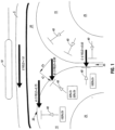
- FIG. 1 is a cross-sectional view of a subject's head 5 with a B-shaped coil 10 positioned thereabove.
- the head includes the scalp and skull 5, the cerebral cortex or grey matter 15, cerebrospinal fluid (CSF) 20, and white matter 25.
- CSF cerebrospinal fluid
- the cortex is concave, folding inwardly away from the scalp and skull, it is termed a sulcus 35 (pl. sucli).
- the most important components of the cortex are the vertical neurons 40, which are oriented perpendicular to the brain's cortical surface (i.e., perpendicular to the interface between cortex 15 and CSF 20).
- the vertical neurons collectively form the cortical columns (not shown), which are the dominant anatomical and physiological features of cerebral cortex (at the microscopic level), being present in all regions of cortex in all mallian species. (Only a few vertical neurons are illustrated in Figure 1 ).
- the TMS coil 10 is positioned and oriented to create an induced E-field that is perpendicular to the brain cortical surface (and parallel to the vertical neurons) in the sulcus ( C ), but parallel to the cortical surface (and perpendicular to the vertical neurons) at the crown of the gyrus ( A ).
- the magnitude of the E field is weaker at C than at A, because the distance from the surface of the TMS coil 10 is greater at C than at A.
- the E field can be decomposed into vertical (E v ) and horizontal (E h ) components, which are parallel to the vertical neurons and horizontal fibers, respectively.
- E has no effect (no E v component) where E is perpendicular to the column ( A ); intermediate effects for intermediate relative orientations ( B ); and maximal effect where E is parallel to the column ( C ).
- the CCCAP may be used to allow the cortical excitation effects of TMS to be computed in advance for any position and orientation, thereby enabling computer-aided aiming of TMS.
- the CCCAP may be used for manual aiming and orienting.
- the CCCAP may also be used to normalize (correct) observed biological effects for the angle of intersection with the cortex, when aiming is done conventionally (i.e., not with CCCAP) but images are obtained showing the relationship between the TMS coil and the cortical surface.
- image-guided, computer-aided implementation of the CCCAP for TMS delivery may be effected in accordance with the following steps.
- an imaging stage is performed, in which a high-resolution, anatomical image (e.g., a 3D Tl-weighted image) of the subject's head is obtained.
- a functional image either functional MRI or PET, for example
- conditions task/control pair
- selectively activate the cortical region of interest e.g., repetitive hand movement to activate the supplementary motor area.
- a modeling stage is performed to identify surfaces within the anatomical and functional images, to be used for registration of the functional and anatomical images to one another and, subsequently, to the patient.
- the scalp surface and the brain's cortical surface are segmented and modeled as polygon-mesh surfaces.
- the brain-surface is modeled at high-resolution, to provide an accurate, detailed representation of the interface between cerebrospinal fluid (CSF) and cortical grey matter, as this is critical for establishing the orientation of the cortical columns.
- CSF cerebrospinal fluid
- Anatomical surface extraction and modeling is done in a manner keeping both surface models (scalp and brain) in register with the original image and, thereby, with one another.
- the brain surface is segmented and modeled as a polygon mesh surface (but with less detail than the model derived from the anatomical image) and the targeted site is identified.
- the two brain surface models (anatomical-image-derived and functional-image-derived) are co-registered, thereby bringing the target site in register with the two MRI-derived cortical surface models: brain and scalp. This comprises a conjoined functional/anatomical model.
- TMS coil-surface/E-field model is superimposed on the conjoined functional/anatomical model.
- the TMS coil-surface/E-field model is positioned and oriented so as to obtain maximum biological efficacy (as defined by the CCCAP) at the target point, while keeping the coil surface outside the scalp surface.
- the position and orientation of the TMS coil-surface relative to the conjoined functional/anatomical model may then be stored for subsequent use.
- this data may be used to perform TMS delivery in accordance with the following.
- the subject is placed in the treatment position and the head immobilized, for example, using a thermoplastic mask (Fox et al., 1985).
- a 3-D digitizer e.g., a passive arm digitizer
- a 3-D digitizer may be used to collect a series of points on the scalp surface. These points are used to create a model of the scalp surface in the subject's current head position.
- This model is registered to the conjoined functional/anatomical model previously created, using a rapid, surface matching algorithm, such as a convex hull algorithm (Lancaster et al., 1999).
- the manual digitizer may again be used to collect a set of specific reference points on the surface of the TMS coil, which may be mounted on a multi-joint, calibrated armature, either passive or robotic.
- the translations and rotations needed to move from the present position to the desired position are computed. If the TMS is held by a passive armature, movement is executed manually, with the readout of the coordinates of the armature as feedback. If the TMS is held by a robot, movement is executed automatically, after a safe pathway (avoiding contact with the subject or other obstacles) has been computed. When properly positioned and oriented, TMS delivery is effected.
- placement is extremely precise ( ⁇ 1 mm), much more precise than is possible using hand-held aiming.
- placement can be computed in advance, rather than by trial-and-error, as is done with hand-held aiming for areas with a measurable behavioral response.
- Fourth, the entire process is mathematically speci fied and suitable for computer implementation.
- Fifth, the procedure is suitable for application to any cortical location, not just brain areas in which aiming accuracy can be confirmed by an overt behavioral response.
- Sixth, once the necessary brain images are acquired, trajectories for stimulating any number of functional areas can be computed.
- TMS delivery may be effected by means of a robotic arm.
- a robotic arm allows the TMS coil to be placed and oriented with accuracy and precision of - 1 mm (location) and -- 1 ° (orientation), far exceeding hand-holding. This degree of accuracy and precision is crucial for implementing a high-precision aiming algorithm.
- a robotic arm allows the TMS to be positioned automatically, i.e., under computer control.
- a robotic arm allows the TMS to be positioned rapidly, saving time for the patient, experimentor or clinician.
- a robotic arm can accurately reestablish its position on sequential days, which is needed for experiments and treatments applied over a series of sessions.
- a robotic arm allows the TMS to be moved rapidly from one position to another, allowing treatment of more than one location in a single session.
- a robotic arm allows the TMS to be held immobile for long periods of time, which a person cannot practically or comfortably achieve.
- a robotic arm allows TMS to be delivered during PET imaging, without exposing a human holder to radiation.
- the present disclosure is also directed to an inverse design method to produce a desired electric field profile for transcranial/peripheral nerve magnetic stimulation.
- a method may be used to design a variety of coils.
- Such coils may include multiple winged coils having a concentrated bundle of wires at the center and smooth arcs splayed therefrom at an increasing distance, maintaining the minimum inductance and/or minimum power dissipation possible for a given field profile.
- other coils may be used to produce a spatial gradient across the nerve, maintaining minimum inductance and/or minimum power dissipation.
- Coils may be designed in accordance with the teachings of the present disclosure to incorporate one or more of the following characteristics which aid in the delivery of transcranial magnetic stimulation.
- a coil may be designed to provide for minimum inductance for a given set of field constraints. Further, a coil may be designed to dissipate a minimum amount of power for a given set of field constraints. Similarly, a coil may be designed to provide for minimum inductance and minimum dissipation for a given set of field constraints.
- a coil may be designed with negative turns to reduce the electric field on a patient. Such negative turns also may be provided in a separate layer to similarly reduce electric field on the patient.
- TMS is the most fundamental, unresolved issue for scientific and medical uses of TMS.
- TMS is most often "aimed" merely by observing its behavioral effects.
- primary motor cortex is frequently identified by adjusting coil position/orientation to achieve a contraction of the desired muscle (e.g., abductor pollicis brevis) at the lowest stimulus voltage.
- image-guided aiming has been introduced (below). Even when image-guided, coil orientation relative to brain anatomy has either been ignored (Paus et al., 1997) or empirically derived (Krings et al., 1997), but it is not based upon a general theory of aiming.
- the induced E-field parallels the current in the coil, is maximum in the plane of the coil and falls off rapidly with distance from the surface of the coil.
- Presently known TMS coils are made in two basic geometries: (1) circular (O-shaped, as shown in FIG. 2); and (2 ) double ring (B-shaped, as shown in FIG. 3 ).
- a circular coil induces a circular E-field. Because the current density is evenly distributed around the coil, the E-field is curved and maximum at the edge of the coil rather than at the center. This lack of a focal linear "sweet spot" makes a circular coil very difficult to aim.
- a much more focal E-field can be created by placing two circular coils, current flowing in opposite directions (i.e ., clockwise and anti-clockwise), next to each other, creating a B-shaped coil.
- the E-field is enhanced where the coils are near each other, because the electric fields from each coil sum.
- the result is a focal E-field in the center of the coil, oriented parallel to the central region (short-axis) of the B-shaped coil ( FIG. 3 ).
- the strong, focal E-field makes the B-shaped coil much easier to aim and much more likely to induce a focal brain activation (Roth et al., 1991).
- TMS position (placement and orientation) follows no coherent theory.
- Some users position the TMS coil by behavioral optimization e.g., minimum-threshold muscle twitch); some position carefully, but ignore orientation, using the B-nose convention (discussed below); some orient by reference to prior behavioral-optimization studies; none use an aiming theory.
- Day reasoned that "stimuli are likely to activate those neurons nearest the stimulating electrode, that is, those on the convexity of the precentral gyrus".
- Day knew that an O-shaped coil, positioned flat against the scalp, produced a circular E-field tangent to the gyral crown and at a 90° angle (horizontal) to the (vertical) columnar organization of the cortex at the gyral crown.
- Theoretical flaws in the horizontal-fiber hypothesis are readily identified.
- the horizontal-fiber hypothesis postulates that pyramidal motor neurons, located on the anterior bank of the central sulcus, are activated by means of horizontal fibers on the crown of the pre-central gyrus. This is a distance of 0.5-2.0 centimeters. Yet, horizontal fibers extend only 1-2 mm (Jones and Wise, 1978; Jones, 1981). Further, horizontal fibers are isotropic, extending uniformly in all directions within a plane parallel to the cortical surface.
- the isotropism (lack of a preferred orientation) of the horizontal fibers should translate into a lack of a preferred orientation for TMS, as the E-field should excite a roughly equal fraction of the total horizontal-fiber population in any orientation. This has been clearly disproven by some of the very studies which espouse the horizontal-fiber hypothesis. Finally, the horizontal fiber hypothesis is weakened by the fact that the predominant horizontal element providing for horizontal interactions is the basket cell, which "should be considered a class of large inhibitory interneuron" (Jones, 1981). Thus, the hypothesis that TMS excites pyramidal cells by means of horizontal fibers is quite unlikely.
- Hand-held, non-image-guided application of TMS is the norm. This rather casual approach to stimulation position and orientation likely has several contributing factors.
- TMS image-guided TMS
- FEF frontal eye fields
- Cortical surface geometry sulcal/gyral location and orientation was not taken into consideration either for placement or for orientation. Orientation was "B-nose”.
- Anatomical MRI was obtained but was used solely to establish the inverse transformation from the standardized space (Talairach and Tournoux, 1988) to the individual's native image space.
- No functional markers e.g., PET during eye movements
- the response location was imaged with PET, but was not interpreted relative to group or individual cortical geometry nor was any discussion of an aiming theory included.
- Krings (et al. 1997) used a modified SURGICAL ARM ® (Radionics, Burlington, MA) to stimulate primary motor cortex. The purpose of this study was to compare response locations for TMS and EBS, validating TMS for pre-operative mapping of motor cortex. Position was adjusted to achieve a consistent motor response (thumb twitch). Orientation was based on anatomical MRI, positioning a B-shaped coil with the short axis perpendicular to the central sulcus, in keeping with the recommendations of Brasil-Neto et al. (1992) and Mills et al. (1992). However, Krings offers no aiming theory. The orientation rules which Krings cites (Brasil-Neto et al., 1992; Mills et al., 1992) are specific to primary motor cortex and do not constitute a generalized aiming theory.
- the TMS-induced B field falls off rapidly with the distance from the coil.
- the induced B field can be altered by nearby ferro-magnetic materials, via the creation of secondarily induced B-fields.
- the magnitude of a secondarily induced B field is a function of the ⁇ of the metal and the amount of metal; the shape of the secondarily induced B-field is a function of the shape of the object.
- the secondary B field and the TMS B field will sum, which can distort the net B field in a complex manner.
- Materials with high ⁇ are metals.
- interaction between coil and arm may be minimized by creating distance between the TMS coil and arm.
- Biological tissues in general, are paramagnetic, having very small ⁇ ; thus, they do not significantly distort the TMS-induced B field.
- the brain's TMS-induced E field is subject to alterations from biological tissues, as follows. Following the TMS-induced E field, currents flow. At the interfaces of tissues whose conductivities differ, charge accumulates. For the head there are three important conductivity interfaces: 1) air and scalp; 2) scalp and skull (outer table); and 3) skull (inner table) and brain. While minor conductivity differences do exist among the several extracranial tissues (dermis, subdermal fat, galea) and intracranial tissues (i.e., meninges, blood vessels, grey matter, white matter and CSF), these differences are small relative to the three major interfaces above.
- Soft tissues are weak conductors; air and skull are non-conductors (insulators). Charge build up occurs, therefore, at the air-scalp, scalp-skull, and skull-brain boundaries. The shape of the head and skull determines the geometry of the charge build up and, thereby, the precise geometry of the E-field distortion. The greatest change in the TMS-induced E field will occur nearest the accumulated charge. Research continues in this area.
- the CAPs predict the results of the two orientation-optimization experiments in the TMS literature (Brasil-Neto et al., 1992; Mills et al., 1992), and the two PET/TMS papers published to date (Paus et al., 1997; Fox et al., 1997), and an exemplary study testing the aiming principles.
- orientation-effect results are exactly predicted by aiming principles 2 and 3, which predict maximal activation when the E-field is perpendicular to the cortex and a graded response proportionate to the total Ev.
- the vertical component (Ev) of E is maximal when E is perpendicular to the sulcus, as shown in FIG. 1 .
- Experiment 1 By Principle 3, maintaining the E-field at a field orientation but varying the strength of the field should vary the degree of TMS-induced neuronal activity.
- Eight normal volunteers were imaged by PET while undergoing 3-Hz TMS stimulations across a range of intensities. Stimulation was applied to the Supplementary Motor Area on the medial surface of the right frontal lobe of the cerebral hemisphere.
- the E-Feld was oriented perpendicular to the cortical surface, which was also perpendicular to the mid-sagittal plane and exactly 90° rotated from the orientation required by the "B-nose" principle, described above.
- This stimulation produced strong activation on the medial-bank cortical surface at the location in which the E-field was most perpendicular to the cortical surface, as predicted by Principles 2 and 3.
- Response magnitude was highly correlated with TMS E-field strength, as predicted by Principle 3.
- Experiment 2 By Principles 2 and 3, varying the orientation of the TMS E-field relative to the cerebral cortical surface should modulate response magnitude, with the greatest response being observed when the E-field is perpendicular to the cortical surface.
- a TMS stimulator having properties which allow it to generate an E field having a maximum at a clearly defined location, said location being easily placed in close alignment with a subject's head, so that the E field is directed substantially parallel to the cortical column of interest.
- a stimulator or a standard TMS stimulator
- a robotic system to permit for accurate delivery of the E field.
- the aiming principles set forth herein may be used in connection with known TMS delivery modes, and likewise, the novel stimulator and delivery system may be used in TMS delivery modes without use of the aiming principles set forth herein.
- a flat, B-shaped coil such as is most commonly used for TMS, creates an E-field that is oriented tangential to the scalp surface upon which it is placed.
- this E-field configuration is optimal for stimulating the banks of sulci in which the sulcus is oriented perpendicular to the scalp surface (e.g., in Figure 1 ).
- the same principles predict that this E-field configuration will be unable to stimulate the cortical surfaces parallel to the scalp, i.e., the gyral crowns.
- the gyral crowns compose approximately 30% of the total cortical surface.
- a TMS coil capable of stimulating gyral crowns.
- this would require an E-field oriented perpendicular to the gyral crown, i.e., essentially perpendicular to the scalp surface.
- FIG. 7 is an example of a TMS stimulator capable of stimulating gyral crowns.
- TMS stimulator 100 includes a body portion 110 and a coil portion 120.
- the body portion 110 may be made of air, ferrite or other materials with ⁇ > 1.
- Stimulator 100 may be surrounded by a conducting fluid.
- the conducting fluid can fill the central portion of the coil portion 120.
- the conducting fluid can fill the space between the coil and targeted body tissue.
- the purpose of the conducting fluid is to provide efficient induction of the E field produced by stimulator 100 through the tissue surface, directed according to the coil design.
- the body portion 110 may be constructed of a non-conducting material and include an insert through at least a portion of the hollow portion of the cylinder which may be made of a ferromagnetic material such as iron.
- the coil portion 120 may be made of wire, such as copper or the like. Via conductors (not shown in FIG. 7 ), the coil portion 120 is connected to a power supply. The power supply is used to provide a current through the coil, which generates an electric field emanating from the stimulator.
- the power supply may include a high energy capacitor bank, which when discharged provides a high current through the coil portion 120.
- the electrical current may be relatively strong (between about 1000 and 2000 amps) and last for a relatively short period of time (between 50 and 250 microseconds).
- the power supply may include a capacitor bank having a very high storage capacity on the order of 50 microfarads charged to a potential of 2000-6000 volts.
- the capacitor bank is made of high duty material to withstand the current generated.
- the capacitor have a capacitance of 50 MFD and a voltage rating of 7.5 kV may be made physically larger to extend the lifetime from an estimated 10 3 pulses to 10 8 pulses.
- the power supply, conductors, and the TMS stimulator may be water-cooled to reduce operating temperature.
- body portion I 10 may be various shapes, such as cone shaped, cylindrical, ellipsoidal, rectangular, and the like.
- the coil portion 120 is preferably toroidal shaped, however, it is to be understood that the coil may be constructed in various shapes.
- the body portion 110 may comprise a cylinder having a diameter between about 10 and 20 centimeters, and a hollow core having a diameter between about 0.5 and 2.0 centimeters.
- the wire portion 120 extends substantially around the body portion 110 in a toroidal shape.
- the wire used may have a diameter between about 0.1 and 1.0 millimeters.
- the TMS stimulator 100 when energized by an electric current, the TMS stimulator 100 generates a maximum induced electric field extending along the long axis 130 of the body portion 110.
- TMS delivery may be effected via use of a robot. More specifically, a robot having six or more degrees of freedom is used to appropriately position and orient the TMS coil in a precise location and orientation for most effective delivery of induced electric field. Without a sixth degree of freedom, the orientation aspect of the CCCAP described above cannot be implemented. In an example , a surgical robot having five joints may be modified to add a device to hold the TMS stimulator and provide for a sixth degree of freedom. Alternately, a robot having six degrees of freedom may be used.
- the robot may be a medical robot to provide benefits of a robot safe and effective for use with human patients.
- a robot may be controlled by a computing system, such as a PC.
- Robot tool motion and orientation may be controlled from appropriate software programs.
- Such programs may include control for robot arm position monitoring, position modeling, plan movement modeling, and movement model execution.
- sensors may be provided so that XYZ position and angles for each of the joints of the robot arm may be obtained in real time.
- Motion commands may be executed in a coordinate system native to the robot.
- the robot arm may be moved from point to point in a smooth manner using a 3-D mouse, SPACE MOUSE TM , or keyboard input.
- a robot By use of such a robot, maintenance of a pre-specified treatment position may be more precise and accurate than a passive arm or a hand-held device. Furthermore, a robot allows movement through a treatment zone (rather than treatment of a point) and further allows precisely timed treatments of multiple sites in a single session.
- TMS may be effective for use in connection with preoperative mapping, inter-operative monitoring, and treatment of conditions, such as long-term depression, and for clinical activity and functional mapping using TMS and PET.
- a means is provided to export a generic treatment plan.
- a coordinate system may be developed and standardized across different patients, labs, and the like.
- such use of a robot is particularly useful with regard to a treatment program in which a patient is subjected to TMS over a repeated number of days.
- FIG. 8 shows an overview diagram of the NEUROMATE TM system 300 as used in connection with PET imaging.
- the exemplary surgical NEUROMATE TM robotic arm was modified to convert it from a system for frame-based, intra-operative probe positioning into a system for frameless, extra-operative, positioning and orientation of an induced E-field.
- Robotic devices must be used with caution in the presence of persons.
- a robot such as the NEUROMATE TM specifically designed for use by and with humans is desired. Benefits include that it moves slowly, such that it can easily be stopped prior to any collision, loss of electrical power renders it immobile in its current position, i.e., it does not return to a "parking" position or make any sudden motions. Further, such a robot may require a key and a recessed button to actuate, being used only under direct supervision.
- a TMS-coil holder was constructed for the TMS coil to adapt to the NEUROMATE TM .
- the TMS tool-holder included a tool-rotation axis, as lacking this, changing coil orientation would require establishing a new arm posture, with only a very limited number of orientation angles (at a given location) being possible.
- the tool holder serves as a stand-off, creating a distance between the final limb of the robotic arm and the TMS coil. This distance decreases effects of the metal arm on the coil's B and E-fields. In addition, this helps keep the metal arm out of the PET field-of-view, thereby lowering the possibility of PET-image attenuation artifacts.
- the tool holder permits orientation sensing and motorized, computer-controlled coil-orienting. It is to be understood, however, that a tool holder need not include a TMS-rotation axis, and that in other cases (such as a 6-joint robot), the TMS coil may be adapted directly to a robotic arm.
- the TMS-coil tool holder was constructed of fiberglass. However, in other cases, the tool-holder may be made from a number of other materials, such as acrylic, fiberglass, delrin, or the like.
- the tool holder 200 includes a proximal end 210, which may be machined to interface with the robotic arm tool-mounting plate 310.
- the distal end 220 of the holder may have a rod 230 mounted to the TMS coil 100 and allow rotation about the coil's z-axis.
- the robotic arm tool mounting plate 310 comprises the fourth and fifth axes of the robot, and the tool holder 200 comprises the sixth degree of freedom.
- the body of the holder 200 is approximately 8" and houses a plastic belt turning a more proximally placed rod to mechanically link the orientation of the rod 230 and the TMS to the orientation sensor 250.
- a precision rotional sensor 250 may be mounted on the end of the proximal (belt-driven) rod.
- the sensor may be a single turn (340°, 10k ⁇ ) precision resistive potentiometer with +/- 1% linear rating.
- the output of the sensor specifies the orientation of the TMS coil.
- the sensor's output may be conveyed to TMS delivery software via tool-sensing electrical contacts on the robotic arm tool-mounting plate 310. In neurosurgical applications, these contacts are used to monitor the depth of tool (e.g., drill-bit or wire electrode) passed through a stationary tool holder. In the present application, they may be used to monitor orientation rather than depth. Additionally, a stepping motor may be added, allowing active rotations of the TMS coil.
- the NEUROMATE TM was designed as a system for framed stereotaxy.
- a patient is registered to the NEUROMATE TM by having his (or her) head placed within a metal ring that is rigidly mounted to the NEUROMATETM by means of a pedestal attached to a long leg, which forms the base/stand of the NEUROMATETM TM .
- the robotic arm was converted into a frameless stereotactic system, capable of being rapidly registered to a subject in any position within the operating range of the robot arm, including supine in the PET scanner. It is to be understood, however, that the method of the present invention may be used in conjunction with framed stereotaxy.
- this registration process may use a manual digitizer to collect points from the subject's scalp, which may be registered to the scalp surface modeled from that subject's image, such as obtained from MRI.
- the robot may be used in an interactive mode to collect these scalp points.
- a 5-axis manual digitizer may be permanently mounted to the robot chassis for use as required.
- the positional relationship between the digitizer and the TMS probe may be calibrated and thereafter should remain constant, although it is recommended that calibration be verified for each use of the system.
- Typical surgical robotic devices come equipped with a stand designed for framed stereotaxy. This stand has a long foot which prevents it from being placed sufficiently close to the PET for use during TMS/PET.
- a shallow, wide, weighted, four-wheeled, cart may be used having weight and width to prevent tipping.
- the wheels are retractable, to allow the system to be completely stable when in operation, yet re-positionable to optimize placement of the robotic arm relative to the PET.
- passive digitizing arms can be used for image-guided TMS-delivery.
- Both Paus (et al., 1997) and Krings (et al., 1997) used commercially available passive arms designed for frameless stereotaxy to assist with TMS aiming.
- these two systems suffer from significant and virtually identical limitations. Neither can be fixed rigidly in position; that is, both are manual digitizers but neither is a holding device. (Paus mounted the TMS coil to a separate, home-made holding arm; Krings held the TMS coil by hand.)
- Neither system can digitize or visualize tool orientation, as both are five-joint arms with no capability for rotation about a tool axis.
- An active (robotic) arm has clear long-term advantages. Ideally, treatment positions are pre-specified, with the arm moving to and maintaining the treatment position. A robotic system can carry out this function more precisely and more accurately than a passive arm. Further, only a robotic system readily combines the tool aiming and tool holding functions. Finally, only a robotic arm allows movement through a treatment zone (rather than treating at a point) or allow precisely timed treatments of multiple sites in a single session.
- the PET image, the MR image, the manual digitizer, and the robotic arm robot have different coordinate-reference frames.
- a whole-brain, high-resolution (1 mm 3 ), T1-weighted MRI may be used to create a reference space within which all objects become registered.
- This image format provides ample anatomical detail for precise registration.
- all images may be standardized by removing differences in orientation and position between patients.
- each patient's reference MRI may be rotated and translated (but not scaled) to the alignment of the Talairach and Tournoux (1988) atlas.
- This six-parameter spatial normalization (of the reference MRI) may be performed using the previously validated SN software (Lancaster, et. al. 1995).
- This software may be used to freely rotate and translate a 3-D brain image to position it in a standard pose.
- the reference MRI may serve as the reference frame for coordinates from: functional images (PET), the head-surface digitizer; the robotic arm, the TMS coil (held by the arm), the standardized head models; and the TMS-induced B and E fields.
- the robot may be moved in a user-guided visual-feedback mode for manual positioning and holding of the TMS probe.
- the robot may be moved from point to point in a smooth manner using joy stick-like or keyboard input.
- 3-D mouse/joystick such as a SPACE MOUSE TM may be used in conjunction with a supervisory PC controller to send motion commands to the robot's on-board controller.
- Motion commands may be executed relative to: (1) the tool coordinate system referenced to the face of the TMS; (2) a reference MRI (aligned but not scaled to the Talairach & Tournoux [1988] brain); and (3) the global coordinate system native to the robot.
- the supervisory controller may use a robot inverse transformation to calculate joint coordinates needed to accomplish an incremental change of position relative to tool coordinates.
- the calculations may take into account arm configuration and joint rotation limits, and will format the commands to the world space required by the supervisory controller.
- the communication protocol, position-sensing interface specifications, movement sensing interface specifications and complete kinematic equations for the robot arm may be developed using, for example, Microsoft Visual C++ on a Pentium-level PC.
- the protocol used by the supervisory control software to communicate with the robot controller may use RS-232 connections and protocol to send instructions and retrieve supervisor-level data from the controller.
- a Visual C++ application may support all motion type commands, including an exclusive stop command and polling commands for status.
- a second serial port of the PC may be used to get robot arm position data and status.
- the communication protocol may be similar to that for the supervisory control software discussed above.
- a multi-port serial I/O board may be added to the PC to support simultaneous access to both ports from the same computer.
- Supervisory control software routines may be used to read this port and obtain x-y-z position and angles for each of the six joints of the robot arm.
- forward and inverse kinematic equations may be used to specify and modify arm pose.
- the patient's head and the robot may be registered to the MR reference frame for each patient and each TMS session, as accurate positioning of the robot forms the basis for registration of the TMS coil relative to the head.
- Physical coordinates digitized about the surface of the head may be used to register the patient's head and to calibrate the digitizer relative to the MRI reference frame.
- the manual digitizer may be permanently mounted on the robot, enabling direct digitizer-to-robot calibration. Rigid-body coordinate-transformation matrices may be calculated between the robot, the digitizer, and the MR reference frame.
- a manual 3-D digitizer may be used to acquire a "cloud" of distributed points on the patients head in a hat-file format (Pelizzari et al., 1989).
- An MRI surface head-file format
- 6000-7000 points uniformly distributed about the head may be extracted from the subject's standardized MR image using, for example, convex hull (CHSN) registration software (Lancaster et al. 1999).
- a coordinate transformation for calibration may be determined by fitting the digitized hat "cloud" (patient) to the detailed head (MRI) surface.
- the fitting method used may be an iterative least square technique that has been shown to provide excellent results for co-registering PET, CT, and MRI (Lancaster et al., 1997). Patients may be positioned within the PET scanner with head constrained.
- the CHSN software may be used for fitting the hat to the head surfaces and calculating a head-to-MR transform matrix.
- the digitizer-to-MR matrix is identical to the head-to-MR matrix, as both are calculated using the manual digitizer and the head surface.
- the robot-to-digitizer transform matrix may be calculated using fiducials for which both digitizer and robot coordinates can be readily determined.
- a pseudoinverse method may be used to calculate the transformation matrix (Castleman, 1996).
- the robot-to-MR transform matrix may be calculated by concatenating the transform matrices for robot-to-digitizer and digitizer-to-MR.
- the TMS-to-robot calibration transform matrix can be calculated. This may be done with the coil in a designated zero-degree orientation relative to the mount. Three parameters (x-y-z position, coil, tool, or z axis orientation, and rotation about coil, tool, or z-axis) are used to fully aim the TMS coil. These may be determined using the manual digitizer to record fiducials on the coil's x- and y-axes. Using these data, equations to calibrate the robot can be determined and robotic coil aiming enabled. This calibration should remain fixed but may be verified periodically. Coil aiming may be extended to the MR reference frame using the robot-to-MR transform matrix.
- Only position and z-axis orientation are under direct control of the robot.
- the uncontrolled rotation about the z-axis may be calculated for each robot arm position.
- Targeted orientations of the coil about its z-axis may be achieved using the manual digitizer and/or the orientation sensor.
- the PET images may be registered to the MR reference frame for each patient.
- PET images may be co-registered to standardized MR images using, for example, the convex hull (CHSN) registration software (Lancaster et al., 1999).
- Convex hull surface is extracted from both MRI and PET images. These models remove concave regions that are well resolved by MRI but poorly resolved by PET. However, the convex brain surface is identical in both imaging modalities and proves and excellent surface for surface matching and, thereby, volume registration.
- the CHSN software (Lancaster et al., 1999) uses the convex hull of the brain, a simplified surface which is highly similar across imaging modalities, for registration and spatial normalization.
- An iterative least square method is used to fit the convex hull from PET (hat format) to the subject's reference MRI (head format), allowing only rotations and translations of the hat data (Pelizzari et. al., 1989).
- This fitting method has very small error: mean RMS errors, measured as distance between the two convex hulls, were reported to be less than 1 mm (Lancaster et al., 1999).
- a PET-to-MR coordinate transformation matrix may thus be calculated by the CHSN software.
- the E field magnitude of figure-8 coil tends to remain strongest at points along the central axis perpendicular to the plane of the coil (z-axis).
- the E-field magnitude rapidly decreases with increasing distance from the surface of the coil.
- a conductor e.g. brain
- the surface charges reduce the E-field magnitude relative to what its magnitude would be at the same point in air.
- a weak conductor e.g. the brain
- a cortical stimulus-delivery site must be selected.
- the columnar orientation must be determined.
- TMS coil aiming parameters must be determined.
- a model of the TMS E-field (corrected for head-induced distortions) must be determined.
- models of the TMS coil and patient head surface must be provided for collision avoidance.
- these steps may be performed via TMS planning software.
- Site selection may be done interactively while viewing a high-resolution MR image of the brain in three orthogonal views.
- the columnar orientation at the treatment site may be determined from the high-resolution MRI by means of cortical-surface extraction, as cortical columns are oriented perpendicular to the cortical surface.
- the on-axis plan proceeds by determining the TMS coil position for aiming. This may make use of a 3-D front-surface model of the coil and the patient's 3-D head surface model to avoid head contact.
- the coil position closest to the head in which the on-axis E field parallels the cortical columns at the treatment site may be established.
- the TMS coil aiming parameters position, coil z-axis orientation, coil y-axis orientation
- the induced E field may be modeled using on-axis data to predict its magnitude at the delivery site.
- a fully 3-D approach, including effects of the patient head may be modeled for each subject using EMAS (Ansoft, Pittsburgh, PA) and anatomical data derived from CT scans.
- EMAS is a general purpose Maxwell's equations solver. Because of its generality, it is slow and uses a lot of computing resources. Calculation of the electric field for a single coil position may require several hours for interactive, image-guided imaging abbreviation of this computation time is desirable. Computations may be accelerated chiefly by introduction of simplifying assumptions. For example, because the skull is a poor conductor, the magnetic fields produced by induced eddy currents can be safely ignored (Davey et al, 1991). As a consequence, the magnetic field produced by the TMS coil may be modeled as being unaffected by the head. Further, the skull is 100 times less conductive than soft-tissue.
- the skull may be treated as a perfect insulator; treating all regions outside the skull as air.
- the E-fields for an individual could be then be calculated as a perturbation of the pre-computed values.
- field estimates based just on the local skull curvature may be quite accurate and provide considerable computational savings.
- 3-D models of the head and TMS coil surfaces may be defined, and a polygonal model of the surface of the TMS coil created.
- Full-surface polygonal models of each subject's head may be created from the high-resolution 3-D MR image.
- a mask defining the full 3-D volume of the subjects head can be obtained.
- a second volume that is guaranteed to be a minimum distance from the head surface can be created.
- the dilated head volume may be used to model a volume with a realistic safety margin for use in collision avoidance control when moving from point to point about the head.
- the undilated model may serve to determine closest approach without contact in final positioning.
- the surfaces of the head models may be extracted and stored using the marching cubes algorithm and its standard storage format (Schroeder et. al., 1996). Additionally or alternatively, collision avoidance may be provided by the operator (run/stop button with absolute shut-off switch).
- TMS delivery software may be used to position the TMS coil exactly as prescribed by the planning software.
- This software may provide accurate robot-controlled positioning of the TMS coil along and about its z-axis. Additionally, movement and pose strategy may ensure safe, effective operation. Finally, feedback to the delivery software may monitor this operation.
- a graphical user interface may be provided, in which the user is prompted for input and presented with options for delivery of TMS.
- the TMS delivery may proceed and display status information.
- a graphical user interface may monitor movement of the robot/TMS coil about the patient's head.
- Polygonal models developed for collision avoidance may be used for rendering 3-D views of the head and TMS coil body.
- a 3-D polygonal model of the robot with TMS coil mounted may be used to create a real-time 3-D display of the robot moving about the head surface. View orientation may be user-selectable to provide unobstructed viewing of the patient's head.
- This display feature may be provided as animation during treatment planning to simulate delivery.
- TMS coil electrical and cooling lines may be accommodated when selecting best pose.
- Joint configuration may be under control of the supervisor software developed to move the arm, which are computed using the forward and inverse kinematics equations of the robot. The user may be presented with several options and asked to select one for the treatment delivery.
- the robot can position the TMS coil but cannot rotate it about coil's z-axis, therefore the coil angle may be adjusted manually.
- Software may use the manual digitizer to measure the TMS coil z-axis rotation angle.
- the sensor may be used for coil-angle sensing, in preference to the manual digitizer.
- the current and target angle, and the difference may be actively displayed.
- Manual orientation may be done with TMS housing away from the head at the position where the robot has already aligned the coil along its z-axis.
- the z-axis rotation angle sensing may be automated using the precision rotary potentiometer.
- the sensor may be connected to the robot controller via its existing wiring harness. Movement toward the head along this treatment axis may be done after adjusting coil angle.
- the cortical column orientation throughout the treatment volume may be determined by a method using both inner and outer cortical surfaces.
- the first step may be a semi-automated extraction of the cortical surface, using, for example, the MEDx (Version 2.1, Sensor Systems, Inc.) image processing software. This step requires approximately 20 minutes per surface.
- the extracted surface may be refined using morphologic operators (dilation, erosion, and 3-D connectivity routines), also within MEDx.
- Both inner and outer cortical surfaces for the treatment volume including all visible sulci, may be extracted and used to create a binary mask of the cortical columns within the treatment volume.
- the binary mask may be used to create a set of normal vectors that uniformly fill each voxel within the mask.
- a 3-D Euclidean Distance Map (EDM) (Russ 1996, Gonzales and Wood 1992) may be used to fill the binary mask with distances from the outer to the inner surface.
- the EDM may then be smoothed with a 3-D Gaussian filter to produce a smooth gradient of values from the outer to inner cortical surface bounds.
- a normal vector may then be calculated for each voxel within the binary mask from the gradient of EDM values (Schroeder, et. al. 1996). These normal vectors may be converted to unit normal vectors.
- the sense of the unit normal vectors may be to point into the brain (orthodromic column direction). This method, based on the EDM provides a smooth and continuous orientation change for the normal vectors.
- These normal vectors may be used for the orthodromic orientation of the cortical columns for each voxel in the binary mask.
- a 3-D scalar map of columnar component of E-field may be accomplished using 3-D models of the E field accounting for the head a set of coil aiming parameters (position, coil z-axis orientation, and coil rotation), and the 3-D model of cortical column orientations.
- the scalar product of E-field vectors and cortical-column unit vectors can be calculated, yielding E-field magnitude along cortical columns (Volts/cm) for each voxel within the treatment volume.
- the result will be a 3-D scalar map of the columnar component of the E-field throughout the treatment volume.
- This map may be used to overlay onto the MR image to see the planned treatment. Modeled treatment effects may be visualized as a pseudo-color overlay on the anatomical image.
- An option may be provided to display the absolute value of the E-field magnitude, and a method to enable/disable the overlays.
- the user may adjust TMS coil global E-field magnitude and a threshold value for display to see the effect of these on target and non-target cortical regions. Since the E-field scalar map depends on both cortical column and coil orientation, a "jog" feature to interactively reposition the TMS coil may be provided to help the user optimize the magnitude in a targeted region. This jog feature allows small increments of movement along and rotations about the orthogonal tool axes after they have been verified safe (non-interfering with the avoidance volume) by the supervisory controller.
- the metal in the PET gantry might alter the TMS-induced B and E fields. If so, this effect must be included in the E-field modeling.
- the TMS B-field might affect the performance of the PET photo-multiplier tubes, which may be resolved with ⁇ metal shielding during TMS/PET.
- the TMS coil and coil holder may excessively, regionally attenuate the emitted annihilation photons. It is to be understood that standard attenuation corrections may suffice to correct for the effect of the TMS coil.
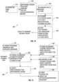
- FIG. 10 is a block diagram of an example TMS treatment planning system.
- a desired site is defined at step 410.
- the desired site may be defined via various imaging techniques, such as fMR1 or PET.
- the TMS delivery parameters may be determined. These parameters may include, for example, the desired pulse rate, duration, TMS stimulator design, and a definition of critical/non-critical regions. Cortical regions may include sites to avoid during treatments or regions of known connectivity to targeted regions that might alter the net stimulation to the targeted region. Non-critical regions might be regions known to have little connectivity to the targeted region.
- the defined site may be registered to the subject's anatomy.
- the registration step may be performed via use of a 3-D MRI.
- planning tasks may be performed. These planning tasks include modeling various elements in order to optimize TMS delivery. These models may include, for example, a 3-D cortical model of the subject's brain, to determine the accurate location of cortical columns and cortex regions.
- a 3-D E-field may be modeled for the chosen TMS stimulator design.
- a 3-D induction model may be performed also. The 3-D induction model is derived from the scalar product of the E-field and the cortical column direction, and is the net volts/cm estimated for cortical columns.
- the TMS treatment plan may be computed.
- the plan may include information regarding optimal coil position, coil orientation, power setting, rate/duration, and a 3-D head model.
- the TMS delivery plan developed at step 450 may then be provided to a TMS treatment delivery system. It is to be understood that the TMS treatment planning system described herein may be performed using a standard personal computer appropriately programmed, or it may be performed via specialized computers, such as a UNIX workstation or a mainframe computer.
- FIG. 11 is an example flow diagram of a TMS treatment delivery system.
- an example TMS treatment delivery system 500 may begin at step 510, in which a patent is positioned with his head immobilized so that a duplicate orientation (the same orientation as used for imaging) may be obtained.
- spatial calibrations may be performed utilizing the data provided by the treatment planning system. Spatial calibrations may include, for example, a robot to digitizer calibration, a digitizer to MRI calibration, and a robot to M RI calibration.
- the robot digitizer spatial calibration may be performed at step 530 in which a physical coil model is acquired via a digitizer and is matched with the robot coil model.
- the digitizer to MRI calibration may be performed in which a physical head model is acquired via the digitizer and is matched with the 3-D MRI head model provided by the TMS treatment planning system, as discussed above.
- the robot-to-digitizer and robot-to-MRI transforms may be concatenated to create a robot-to-MRI transform during calibration.
- safety features may be implemented in which a plan for avoidance of the head during movement of the robot is effected.
- the rate/duration provided by the TMS treatment planning system may be implemented as a control to prevent excess stimulation.
- TMS delivery is effected after the coil is positioned and oriented and the rate, duration, and power of the delivery is set.
- the TMS treatment delivery system may be performed using the computing systems discussed above.
- the stimulation circuit may be considered primarily an LC circuit with a small resistive loss.
- the voltage induced in a conducting body is proportional to this frequency.
- the coil is of interest, and thus the capacitive section may be considered constant.
- the coil inductance may be lowered.
- the target field method may be adapted to provide a coil with a minimum inductance for a given set of electric field constraints.
- the constraints may be set to provide as smooth a design as possible.
- the constraints should also be set such the coil is of a reasonable size in order that the natural field falloff moving away from the coil is not too sharp.
- the theory behind minimum inductance TMS coils may be adapted from known design techniques for target field gradient coil designs for MRI, such as that of Martens et al, and Turner.
- E x ⁇ .
- a x and so E x ⁇ ⁇ 0 8 ⁇ 2 ⁇ ⁇ ⁇ ⁇ ⁇ ⁇ ⁇ 1 ⁇ 2 + ⁇ 2 e i ⁇ x e i ⁇ y e ⁇ ⁇ 2 + ⁇ 2 . z j x ⁇ ⁇ d ⁇ d ⁇
- the electric field must be symmetric in both the x and y directions, so that the imaginary components in the above equation can be reduced to cos( ⁇ x) and cos( ⁇ y).
- the Fourier transform may be used to obtain the current density J x (x,z) and J z (x,z). These may then be integrated to provide a stream function and may be discretized into current loops.
- the accuracy of the design is then dependent on the number of loops chosen to approximate the continuous current density.
- the coil may also be evaluated in the presence of conducting boundaries to simulate a human head using numerical methods such as finite element analysis. The design process does not take into account these boundaries, although an approximation may be incorporated into the design using a conducting sphere and a well-known method of calculating electric field in a spherical volume, as set forth in Eaton (1992).
- the symmetries may be adjusted, i.e. all cos( ⁇ x) need to be changed to sin( ⁇ x).
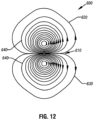
- FIG. 12 shows an example of a coil design developed by an inverse method.
- coil 600 is a two-winged coil design having a first wing 620 and a second wing 630. The wings extend peripherally from a center portion 610.
- coil 600 is a variation of a figure-eight coil design.
- the coil 600 varies from such a standard design, in that the individual wire elements or windings 640 that make up the coil are closely concentrated towards the center portion 610 and extend therefrom in increasing arcs to the periphery of the coil.
- the direction of the electric field traveling through the windings 640 is opposite directions for each of the two wings of the coil. However, the windings 640 making up each of the wings 620 and 630 all travel in the same direction.
- the spacing between windings 640 may vary in given examples. As shown in FIG. 12 , there are approximately 12 wires in each wing of the coil. However, it is to be understood that more or fewer windings may be present in a given design. Further, the wings 620 and 630 are generally shown as mirror opposites. However, it is to be understood that in certain examples, the wings may have different eccentricities.
- the coil may be designed in accordance with standard practices for coil manufacture well-known to those with skill in the art.
- the windings may comprise copper or another conducting material, such as silver (or other conducting material) ribbon placed on its edge.
- Such wire may have a diameter of between about 0.1 and 1.0 millimeters in the examples.
- the coil may be encased in plastic or another non-conducting material in order for reasons of safety and other issues.
- the coil may be encased in thermally conductive epoxy to enhance heat dissipation.
- the coil may be encased with a water, oil or air cooling system. Coils may also be wound in layers placed directly upon one another, and connected in series or parallel.
- the wire pattern may be transferred to a sheet former for construction using a computerized milling machine, or may be transferred using heat from an inked hard copy, such as a computer printout.
- the wire pattern may be constructed from one single wire/ribbon wound with small connecting paths between loops. Standard connections from the coil to cabling necessary to adapt the coil to a magnetic stimulator may be made.
- the method may be changed slightly to provide a minimum inductance configuration providing a spatial gradient in the electric field for peripheral nerve stimulation. An example of this is shown in FIG. 13 .
- FIG. 13 is a top view of an alternate coil design.
- coil 700 is a four-winged coil having four wings 720.
- Each of the wings 720 has a first set of windings 722 and a second set of windings 724.
- each of the wings 720 is generally a variation of a figure-eight coil, in which the more centrally located portion 722 is smaller than the peripherally located portion 724.
- This coil may be designed similarly to coil 600 discussed above, in that each of the portions of each wing 720 may be designed so that the windings are concentrated more closely towards the interior portion of the coil and extending therefrom in increasing arcs. This is especially the case for the peripheral portion 724.
- the coil may be designed in a generally square manner.
- the coil shown at FIG. 13 may be constructed in accordance with well-known principles for coil manufacture, as discussed above.
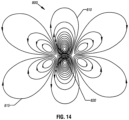
- FIG. 14 is a diagram of another coil example created by an inverse design method.
- coil 800 is a 6-winged coil having two central windings 810 and four outer windings 815 in which the outer windings 815 extend peripherally from center portion 820 in increasing arcs.
- This coil was designed using constraints on the x-component of the electric field.
- the coil dimensions may be approximately 36 cm (x-direction) by 28 cm (y-direction), substantially larger than the B-shaped coil.
- the current density may be apodized (basically, outside a certain region the current density may be multiplied by an exponential function so that the outer rings are effectively shrunk).
- the electric field may then be recalculated to determine the significance of the effect.
- constraints in this example were set such that the x-component of the electric field at the center point was twice that of a point at 2.5 cm along the x and y axes and 3 cm from the coil. That is, the constraints were: x(cm) y z E-field (V/m) 0.0 0.0 3.0 100 2.5 1.1 3.0 50 0.0 2.5 3.0 50
- FIGS. 15 and 16 are graphical representations of the electric field magnitude/current along the x and y axes, respectively.
- the current required to obtain a field of 100 V/m at the central point was 2951 amps, assuming an excitation waveform frequency of 5 Khz.
- the coil inductance was estimated to be 20uH.
- the three constraints (one at the center, one each on + x and y axes) represent an attempt to localize the generated field inside a given region. Other constraints (- x and y axes) are implied by symmetry.
- the four outer windings 815 serve to limit the extent of the field in the x-direction.
- the central windings 810 provide the main field generation and limit the field extent in the y-direction. Further, the smooth spreading of the wire paths serves to reduce mutual inductances between wires.
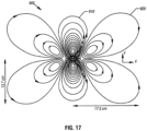
- FIG. 17 is a diagram of an alternate coil example.
- coil 900 is a 6-winged coil having two central coils 910 and four outer coils 920.
- the coil of FIG. 17 differs from the coil of FIG. 14 in that the central coils 910 include several negative turns in order to reduce the magnitude of the electric field.
- the negative turns are shown more specifically in FIG. 18 , which is a close up of the central coils 910.
- the central coils 910 include a plurality of first turns 930 and a plurality of second turns 940.
- the second turns 940 are configured in the opposite direction and carry current having the opposite polarity of the current carried by the first turns 930.
- the negative turns may be located in a separate layer from turns having an opposite polarity.
- small secondary coil consisting of a few turns of either a figure 8 design, or a smaller version of the target field designs disclosed herein, may be placed next to the magnetic stimulation coil such that the center of the coils are coincident but such that the distance between them is adjustable.
- the current may flow in the second coil such that the electric field generated by the current pulse is opposing the direction of the field produced by the main coil. Further, the angle that the loops make to the surface of the coil may also be adjusted.
- coil designs disclosed herein may be used independently from the delivery methods herein. Further, it is to be understood that the delivery methods disclosed may be used independently from the coils herein.
Applications Claiming Priority (5)
| Application Number | Priority Date | Filing Date | Title |
|---|---|---|---|
| US28867001P | 2001-05-04 | 2001-05-04 | |
| US288670P | 2001-05-04 | ||
| PCT/US2002/014157 WO2002089902A2 (en) | 2001-05-04 | 2002-05-03 | Apparatus and methods for delivery of transcranial magnetic stimulation |
| US138543 | 2002-05-03 | ||
| US10/138,543 US7087008B2 (en) | 2001-05-04 | 2002-05-03 | Apparatus and methods for delivery of transcranial magnetic stimulation |
Publications (4)
| Publication Number | Publication Date |
|---|---|
| EP1383572A2 EP1383572A2 (en) | 2004-01-28 |
| EP1383572A4 EP1383572A4 (en) | 2006-01-04 |
| EP1383572B1 EP1383572B1 (en) | 2011-07-20 |
| EP1383572B2 true EP1383572B2 (en) | 2023-06-21 |
Family
ID=26836305
Family Applications (1)
| Application Number | Title | Priority Date | Filing Date |
|---|---|---|---|
| EP02724022.5A Expired - Lifetime EP1383572B2 (en) | 2001-05-04 | 2002-05-03 | Method of planning delivery of transcranial magnetic stimulation |
Country Status (7)
Families Citing this family (214)
| Publication number | Priority date | Publication date | Assignee | Title |
|---|---|---|---|---|
| US7092748B2 (en) * | 2000-02-18 | 2006-08-15 | Centro Nacional De Investigaciones Cientificas (Cnic) | System and method for the tomography of the primary electric current of the brain and of the heart |
| US7117033B2 (en) * | 2000-05-08 | 2006-10-03 | Brainsgate, Ltd. | Stimulation for acute conditions |
| US20020097125A1 (en) * | 2000-06-05 | 2002-07-25 | Kent Davey | Method for optimizing transcranial magnetic stimulation cores and magnetic cores produced thereby |
| US8047979B2 (en) | 2001-04-20 | 2011-11-01 | Mclean Hospital Corporation | Magnetic field treatment techniques |
| EP1269913B1 (de) * | 2001-06-28 | 2004-08-04 | BrainLAB AG | Vorrichtung für transcraniale magnetische Stimulation und kortikale Kartographie |
| ES2238365T3 (es) * | 2001-06-28 | 2005-09-01 | Brainlab Ag | Aparato de estimulacion magnetica transcraneal. |
| AU2003218433A1 (en) * | 2002-03-25 | 2003-10-13 | Musc Foundation For Research Development | Methods and systems for using transcranial magnetic stimulation to enhance cognitive performance |
| US7684859B2 (en) * | 2002-04-25 | 2010-03-23 | Brainsgate Ltd. | Stimulation of the OTIC ganglion for treating medical conditions |
| WO2003098268A1 (en) * | 2002-05-17 | 2003-11-27 | Musc Foundation For Research Development | Method, apparatus, and system for automatically positioning a probe or sensor |
| FI20021050A (fi) * | 2002-05-31 | 2003-12-01 | Nexstim Oy | Aivojen magneettistimulaation kohdennusmenetelmä ja -laitteisto |
| WO2004006750A2 (en) * | 2002-07-15 | 2004-01-22 | Musc Foundation For Research Development | Functional magnetic resonance imaging guided transcranial magnetic stimulation deception inhibitor |
| EP1531749A2 (en) * | 2002-08-13 | 2005-05-25 | Microbotics Corporation | Microsurgical robot system |
| US7539528B2 (en) * | 2002-09-20 | 2009-05-26 | Jinhu Xiong | Using magnetic resonance imaging to directly map neuronal activity |
| FI113615B (fi) * | 2002-10-17 | 2004-05-31 | Nexstim Oy | Kallonmuodon ja sisällön kolmiulotteinen mallinnusmenetelmä |
| US7561919B2 (en) * | 2002-11-14 | 2009-07-14 | Brainsgate Ltd. | SPG stimulation via the greater palatine canal |
| US7228178B2 (en) * | 2002-11-22 | 2007-06-05 | International Rehabilitative Sciences, Inc. | Surface stimulation for tremor control |
| US8118722B2 (en) | 2003-03-07 | 2012-02-21 | Neuronetics, Inc. | Reducing discomfort caused by electrical stimulation |
| US7153256B2 (en) * | 2003-03-07 | 2006-12-26 | Neuronetics, Inc. | Reducing discomfort caused by electrical stimulation |
| CA2530532A1 (en) * | 2003-06-27 | 2005-01-06 | Fralex Therapeutics Inc. | System for image-guided pulsed magnetic field diagnosis and treatment |
| ATE372811T1 (de) * | 2003-08-04 | 2007-09-15 | Brainlab Ag | Vorrichtung zum berechnen einer energiemenge zur stimulation des gehirns |
| US7711431B2 (en) | 2003-08-04 | 2010-05-04 | Brainlab Ag | Method and device for stimulating the brain |
| JP4403453B2 (ja) * | 2003-11-13 | 2010-01-27 | 株式会社島津製作所 | 頭表座標を脳表座標に変換する方法と、その変換データを利用する経頭蓋的脳機能測定装置 |
| US7104947B2 (en) | 2003-11-17 | 2006-09-12 | Neuronetics, Inc. | Determining stimulation levels for transcranial magnetic stimulation |
| US7422555B2 (en) * | 2003-12-30 | 2008-09-09 | Jacob Zabara | Systems and methods for therapeutically treating neuro-psychiatric disorders and other illnesses |
| US7651459B2 (en) * | 2004-01-06 | 2010-01-26 | Neuronetics, Inc. | Method and apparatus for coil positioning for TMS studies |
| US6972567B2 (en) * | 2004-01-15 | 2005-12-06 | Ge Medical Systems Global Technology Company, Llc | Gradient coil and method for construction |
| US9233245B2 (en) | 2004-02-20 | 2016-01-12 | Brainsgate Ltd. | SPG stimulation |
| US8010189B2 (en) * | 2004-02-20 | 2011-08-30 | Brainsgate Ltd. | SPG stimulation for treating complications of subarachnoid hemorrhage |
| US8055347B2 (en) | 2005-08-19 | 2011-11-08 | Brainsgate Ltd. | Stimulation for treating brain events and other conditions |
| US20050215889A1 (en) * | 2004-03-29 | 2005-09-29 | The Board of Supervisory of Louisiana State University | Methods for using pet measured metabolism to determine cognitive impairment |
| US8052591B2 (en) * | 2006-05-05 | 2011-11-08 | The Board Of Trustees Of The Leland Stanford Junior University | Trajectory-based deep-brain stereotactic transcranial magnetic stimulation |
| US7520848B2 (en) * | 2004-04-09 | 2009-04-21 | The Board Of Trustees Of The Leland Stanford Junior University | Robotic apparatus for targeting and producing deep, focused transcranial magnetic stimulation |
| US8177702B2 (en) | 2004-04-15 | 2012-05-15 | Neuronetics, Inc. | Method and apparatus for determining the proximity of a TMS coil to a subject's head |
| US7601115B2 (en) * | 2004-05-24 | 2009-10-13 | Neuronetics, Inc. | Seizure therapy method and apparatus |
| WO2006021957A2 (en) * | 2004-08-23 | 2006-03-02 | Brainsgate Ltd. | Concurrent bilateral spg modulation |
| US9820658B2 (en) | 2006-06-30 | 2017-11-21 | Bao Q. Tran | Systems and methods for providing interoperability among healthcare devices |
| US7857746B2 (en) | 2004-10-29 | 2010-12-28 | Nueronetics, Inc. | System and method to reduce discomfort using nerve stimulation |
| US8088058B2 (en) * | 2005-01-20 | 2012-01-03 | Neuronetics, Inc. | Articulating arm |
| US11583691B1 (en) * | 2005-01-21 | 2023-02-21 | Michael Sasha John | Methods for neuro-cardiac guided magnetic stimulation therapy |
| US20060199159A1 (en) * | 2005-03-01 | 2006-09-07 | Neuronetics, Inc. | Head phantom for simulating the patient response to magnetic stimulation |
| US7396326B2 (en) * | 2005-05-17 | 2008-07-08 | Neuronetics, Inc. | Ferrofluidic cooling and acoustical noise reduction in magnetic stimulators |
| US7976451B2 (en) | 2005-06-16 | 2011-07-12 | The United States Of America As Represented By The Department Of Health And Human Services | Transcranial magnetic stimulation system and methods |
| US7824324B2 (en) | 2005-07-27 | 2010-11-02 | Neuronetics, Inc. | Magnetic core for medical procedures |
| US7733224B2 (en) | 2006-06-30 | 2010-06-08 | Bao Tran | Mesh network personal emergency response appliance |
| US9037247B2 (en) * | 2005-11-10 | 2015-05-19 | ElectroCore, LLC | Non-invasive treatment of bronchial constriction |
| US10441780B2 (en) | 2005-11-10 | 2019-10-15 | Electrocore, Inc. | Systems and methods for vagal nerve stimulation |
| US9126050B2 (en) | 2009-03-20 | 2015-09-08 | ElectroCore, LLC | Non-invasive vagus nerve stimulation devices and methods to treat or avert atrial fibrillation |
| US8868177B2 (en) | 2009-03-20 | 2014-10-21 | ElectroCore, LLC | Non-invasive treatment of neurodegenerative diseases |
| US9089719B2 (en) * | 2009-03-20 | 2015-07-28 | ElectroCore, LLC | Non-invasive methods and devices for inducing euphoria in a patient and their therapeutic application |
| US20110125203A1 (en) * | 2009-03-20 | 2011-05-26 | ElectroCore, LLC. | Magnetic Stimulation Devices and Methods of Therapy |
| US11297445B2 (en) | 2005-11-10 | 2022-04-05 | Electrocore, Inc. | Methods and devices for treating primary headache |
| US8676330B2 (en) | 2009-03-20 | 2014-03-18 | ElectroCore, LLC | Electrical and magnetic stimulators used to treat migraine/sinus headache and comorbid disorders |
| US11351363B2 (en) | 2005-11-10 | 2022-06-07 | Electrocore, Inc. | Nerve stimulation devices and methods for treating cardiac arrhythmias |
| US9174066B2 (en) | 2009-03-20 | 2015-11-03 | ElectroCore, LLC | Devices and methods for non-invasive capacitive electrical stimulation and their use for vagus nerve stimulation on the neck of a patient |
| US10537728B2 (en) | 2005-11-10 | 2020-01-21 | ElectroCore, LLC | Vagal nerve stimulation to avert or treat stroke or transient ischemic attack |
| US20070135859A1 (en) * | 2005-12-09 | 2007-06-14 | Peter Eriksson | Use of transcranial magnetic stimulation to improve memory and stress related syndromes in humans |
| US8267850B2 (en) * | 2007-11-27 | 2012-09-18 | Cervel Neurotech, Inc. | Transcranial magnet stimulation of deep brain targets |
| US9352167B2 (en) | 2006-05-05 | 2016-05-31 | Rio Grande Neurosciences, Inc. | Enhanced spatial summation for deep-brain transcranial magnetic stimulation |
| US7539532B2 (en) | 2006-05-12 | 2009-05-26 | Bao Tran | Cuffless blood pressure monitoring appliance |
| US9060683B2 (en) | 2006-05-12 | 2015-06-23 | Bao Tran | Mobile wireless appliance |
| US8500636B2 (en) | 2006-05-12 | 2013-08-06 | Bao Tran | Health monitoring appliance |
| US7558622B2 (en) | 2006-05-24 | 2009-07-07 | Bao Tran | Mesh network stroke monitoring appliance |
| US8684922B2 (en) | 2006-05-12 | 2014-04-01 | Bao Tran | Health monitoring system |
| US8968195B2 (en) | 2006-05-12 | 2015-03-03 | Bao Tran | Health monitoring appliance |
| US8323189B2 (en) | 2006-05-12 | 2012-12-04 | Bao Tran | Health monitoring appliance |
| US8684900B2 (en) | 2006-05-16 | 2014-04-01 | Bao Tran | Health monitoring appliance |
| US7539533B2 (en) | 2006-05-16 | 2009-05-26 | Bao Tran | Mesh network monitoring appliance |
| US8488895B2 (en) * | 2006-05-31 | 2013-07-16 | Indiana University Research And Technology Corp. | Laser scanning digital camera with pupil periphery illumination and potential for multiply scattered light imaging |
| US8545378B2 (en) | 2006-06-15 | 2013-10-01 | The Trustees Of Columbia University In The City Of New York | Systems and methods for inducing electric field pulses in a body organ |
| US7753836B2 (en) * | 2006-06-15 | 2010-07-13 | The Trustees Of Columbia University In The City Of New York | Systems and methods for inducing electric field pulses in a body organ |
| US20090210026A1 (en) * | 2006-08-17 | 2009-08-20 | Brainsgate Ltd. | Spg stimulation for enhancing neurogenesis and brain metabolism |
| WO2008033792A2 (en) * | 2006-09-11 | 2008-03-20 | Neuroquest Therapeutics | Repetitive transcranial magnetic stimulation for movement disorders |
| US9101751B2 (en) * | 2006-09-13 | 2015-08-11 | Nexstim Oy | Method and system for displaying the electric field generated on the brain by transcranial magnetic stimulation |
| US7925066B2 (en) * | 2006-09-13 | 2011-04-12 | Nexstim Oy | Method and apparatus for correcting an error in the co-registration of coordinate systems used to represent objects displayed during navigated brain stimulation |
| WO2008070001A2 (en) * | 2006-12-01 | 2008-06-12 | Beth Israel Deaconess Medical Center, Inc. | Transcranial magnetic stimulation (tms) methods and apparatus |
| US8128549B2 (en) | 2007-02-20 | 2012-03-06 | Neuronetics, Inc. | Capacitor failure detection |
| JP5527731B2 (ja) | 2007-04-16 | 2014-06-25 | ニューロアーム サージカル エル ティ ディー | レジストレーションに有用な方法、デバイス、およびシステム |
| EP2152183B1 (en) | 2007-04-23 | 2014-06-11 | Medtronic Navigation, Inc. | Apparatus for electromagnetic navigation of a magnetic stimulation probe |
| US8750971B2 (en) | 2007-05-24 | 2014-06-10 | Bao Tran | Wireless stroke monitoring |
| ES2310975B1 (es) * | 2007-07-09 | 2009-09-03 | LABORATORIOS BZ I&D, S.L. | Regulador biofisiologico para tratamientos terapeuticos. |
| US8956273B2 (en) * | 2007-08-20 | 2015-02-17 | Cervel Neurotech, Inc. | Firing patterns for deep brain transcranial magnetic stimulation |
| US20100185042A1 (en) * | 2007-08-05 | 2010-07-22 | Schneider M Bret | Control and coordination of transcranial magnetic stimulation electromagnets for modulation of deep brain targets |
| WO2009033150A1 (en) * | 2007-09-08 | 2009-03-12 | Neostim, Inc. | Pitch, roll, and yaw motions for electromagnet arrays |
| WO2009020938A1 (en) * | 2007-08-05 | 2009-02-12 | Neostim, Inc. | Monophasic multi-coil arrays for trancranial magnetic stimulation |
| WO2009055634A1 (en) * | 2007-10-24 | 2009-04-30 | Neostim Inc. | Intra-session control of transcranial magnetic stimulation |
| US8956274B2 (en) * | 2007-08-05 | 2015-02-17 | Cervel Neurotech, Inc. | Transcranial magnetic stimulation field shaping |
| WO2009036040A1 (en) * | 2007-09-10 | 2009-03-19 | Neostim, Inc. | Automated movement of electromagnets tracking eccentricity of the head |
| WO2009023162A1 (en) * | 2007-08-11 | 2009-02-19 | The Johns Hopkins University | Focal noninvasive stimulation of the sensory cortex of a subject with cerebral palsy |
| WO2009023680A1 (en) * | 2007-08-13 | 2009-02-19 | Neostim, Inc. | Gantry and switches for position-based triggering of tms pulses in moving coils |
| WO2009033192A1 (en) * | 2007-09-09 | 2009-03-12 | Neostim, Inc. | Focused magnetic fields |
| DE102007044874B4 (de) * | 2007-09-20 | 2014-08-21 | Siemens Aktiengesellschaft | Verfahren zur Ermittlung von Schwächungswerten für PET-Daten eines Patienten |
| US8265910B2 (en) * | 2007-10-09 | 2012-09-11 | Cervel Neurotech, Inc. | Display of modeled magnetic fields |
| DE102008021573A1 (de) * | 2007-10-16 | 2009-04-23 | Neue Magnetodyn Gmbh | Spulenanordnung zum Erzeugen therapeutischer elektromagnetischer Felder |
| DE102007049542A1 (de) | 2007-10-16 | 2009-04-23 | Neue Magnetodyn Gmbh | Implantierbare Vorrichtung, System zum Erzeugen lokalisierter elektromagnetischer Felder im Bereich eines Implantats und Spulenanordnung |
| EP2050483A1 (de) * | 2007-10-16 | 2009-04-22 | Neue Magnetodyn GmbH | Spulenanordnung zum Erzeugen therapeutischer elektromagnetischer Felder |
| US7860569B2 (en) | 2007-10-18 | 2010-12-28 | Brainsgate, Ltd. | Long-term SPG stimulation therapy for prevention of vascular dementia |
| US20100286468A1 (en) * | 2007-10-26 | 2010-11-11 | David J Mishelevich | Transcranial magnetic stimulation with protection of magnet-adjacent structures |
| WO2009063435A1 (en) * | 2007-11-14 | 2009-05-22 | Mcgill University | Apparatus and method for treating a cortical-based visual disorder using transcranial magnetic stimulation |
| WO2009086071A2 (en) * | 2007-12-20 | 2009-07-09 | Mayo Foundation For Medical Education And Research | Systems and methods for magnetic-assisted therapeutic agent delivery |
| US8179135B2 (en) * | 2008-01-28 | 2012-05-15 | California Institute Of Technology | Low field electron paramagnetic resonance imaging with SQUID detection |
| US9884200B2 (en) * | 2008-03-10 | 2018-02-06 | Neuronetics, Inc. | Apparatus for coil positioning for TMS studies |
| US20110105826A1 (en) * | 2008-05-23 | 2011-05-05 | Neostim, Inc. | Transcranial magnetic stimulation by enhanced magnetic field perturbations |
| US20110124976A1 (en) * | 2008-08-15 | 2011-05-26 | Koninklijke Philips Electronics N.V. | Model enhanced imaging |
| US20100114184A1 (en) * | 2008-10-07 | 2010-05-06 | Brainsgate Ltd. | Flexible tools for preparing bony canals |
| US8882651B2 (en) * | 2008-10-31 | 2014-11-11 | Nexstim Oy | Magnetic stimulation coils with electrically conducting structures |
| WO2010049575A1 (en) * | 2008-10-31 | 2010-05-06 | Nexstim Oy | Method, apparatus and computer program for non-invasive brain stimulation when target muscles are suitably active |
| US8795148B2 (en) * | 2009-10-26 | 2014-08-05 | Cervel Neurotech, Inc. | Sub-motor-threshold stimulation of deep brain targets using transcranial magnetic stimulation |
| US9180305B2 (en) * | 2008-12-11 | 2015-11-10 | Yeda Research & Development Co. Ltd. At The Weizmann Institute Of Science | Systems and methods for controlling electric field pulse parameters using transcranial magnetic stimulation |
| WO2010080879A2 (en) | 2009-01-07 | 2010-07-15 | Neostim, Inc. | Shaped coils for transcranial magnetic stimulation |
| US20100185041A1 (en) * | 2009-01-20 | 2010-07-22 | Lee Richard H | Cylindrical magnetic field projection method |
| US9067052B2 (en) * | 2009-03-02 | 2015-06-30 | Yeda Research And Development Co., Ltd. At The Weizmann Institute Of Science | Magnetic configuration and timing scheme for transcranial magnetic stimulation |
| US10376696B2 (en) | 2009-03-20 | 2019-08-13 | Electrocore, Inc. | Medical self-treatment using non-invasive vagus nerve stimulation |
| US9333347B2 (en) | 2010-08-19 | 2016-05-10 | ElectroCore, LLC | Devices and methods for non-invasive electrical stimulation and their use for vagal nerve stimulation on the neck of a patient |
| US11229790B2 (en) | 2013-01-15 | 2022-01-25 | Electrocore, Inc. | Mobile phone for treating a patient with seizures |
| US10286212B2 (en) | 2009-03-20 | 2019-05-14 | Electrocore, Inc. | Nerve stimulation methods for averting imminent onset or episode of a disease |
| US9375571B2 (en) | 2013-01-15 | 2016-06-28 | ElectroCore, LLC | Mobile phone using non-invasive nerve stimulation |
| US9174045B2 (en) | 2009-03-20 | 2015-11-03 | ElectroCore, LLC | Non-invasive electrical and magnetic nerve stimulators used to treat overactive bladder and urinary incontinence |
| US10232178B2 (en) | 2009-03-20 | 2019-03-19 | Electrocore, Inc. | Non-invasive magnetic or electrical nerve stimulation to treat or prevent dementia |
| US10220207B2 (en) | 2009-03-20 | 2019-03-05 | Electrocore, Inc. | Nerve stimulation methods for averting imminent onset or episode of a disease |
| US9254383B2 (en) | 2009-03-20 | 2016-02-09 | ElectroCore, LLC | Devices and methods for monitoring non-invasive vagus nerve stimulation |
| US10512769B2 (en) | 2009-03-20 | 2019-12-24 | Electrocore, Inc. | Non-invasive magnetic or electrical nerve stimulation to treat or prevent autism spectrum disorders and other disorders of psychological development |
| US9403001B2 (en) | 2009-03-20 | 2016-08-02 | ElectroCore, LLC | Non-invasive magnetic or electrical nerve stimulation to treat gastroparesis, functional dyspepsia, and other functional gastrointestinal disorders |
| US10252074B2 (en) | 2009-03-20 | 2019-04-09 | ElectroCore, LLC | Nerve stimulation methods for averting imminent onset or episode of a disease |
| US8018232B2 (en) * | 2009-03-31 | 2011-09-13 | General Electric Company | Interleaved gradient coil for magnetic resonance imaging |
| WO2010135425A1 (en) * | 2009-05-19 | 2010-11-25 | The Trustees Of Columbia University In The City Of New York | Systems and methods for inducing electric field pulses in a body organ |
| GB0909281D0 (en) | 2009-05-29 | 2009-07-15 | Magstim Company The Ltd | Device positioning system |
| US8911342B2 (en) | 2009-06-22 | 2014-12-16 | Re5 Aps | Apparatus and method for pulsed electrical field treatment |
| CN102754125B (zh) * | 2009-12-10 | 2016-05-25 | 皇家飞利浦电子股份有限公司 | 用于创伤性脑损伤的快速精确定量评估的系统 |
| WO2011100211A2 (en) * | 2010-02-10 | 2011-08-18 | Neostim, Inc. | Power management in transcranial magnetic stimulators |
| CA2796426A1 (en) | 2010-05-02 | 2011-11-10 | Lake Biosciences, Llc | Modulating function of the facial nerve system or related neural structures via the ear |
| US9272157B2 (en) | 2010-05-02 | 2016-03-01 | Nervive, Inc. | Modulating function of neural structures near the ear |
| US9492679B2 (en) | 2010-07-16 | 2016-11-15 | Rio Grande Neurosciences, Inc. | Transcranial magnetic stimulation for altering susceptibility of tissue to pharmaceuticals and radiation |
| US11191953B2 (en) | 2010-08-19 | 2021-12-07 | Electrocore, Inc. | Systems and methods for vagal nerve stimulation |
| US11400288B2 (en) | 2010-08-19 | 2022-08-02 | Electrocore, Inc | Devices and methods for electrical stimulation and their use for vagus nerve stimulation on the neck of a patient |
| US9358381B2 (en) | 2011-03-10 | 2016-06-07 | ElectroCore, LLC | Non-invasive vagal nerve stimulation to treat disorders |
| US20200086108A1 (en) | 2010-08-19 | 2020-03-19 | Electrocore, Inc. | Vagal nerve stimulation to reduce inflammation associated with an aneurysm |
| JP5896109B2 (ja) * | 2010-11-25 | 2016-03-30 | 国立大学法人大阪大学 | 治療用磁気コイルユニット |
| US11432760B2 (en) | 2011-01-12 | 2022-09-06 | Electrocore, Inc. | Devices and methods for remote therapy and patient monitoring |
| JP6161004B2 (ja) | 2011-03-09 | 2017-07-12 | 国立大学法人大阪大学 | 画像データ処理装置および経頭蓋磁気刺激装置 |
| US11511109B2 (en) | 2011-03-10 | 2022-11-29 | Electrocore, Inc. | Non-invasive magnetic or electrical nerve stimulation to treat gastroparesis, functional dyspepsia, and other functional gastrointestinal disorders |
| US8949088B2 (en) | 2011-03-10 | 2015-02-03 | Magforce Ag | Computer-aided simulation tool for providing assistance in the planning of thermotherapy |
| US11458297B2 (en) | 2011-03-10 | 2022-10-04 | Electrocore, Inc | Electrical and magnetic stimulators used to treat migraine/sinus headache, rhinitis, sinusitis, rhinosinusitis, and comorbid disorders |
| US10173048B2 (en) | 2011-03-10 | 2019-01-08 | Electrocore, Inc. | Electrical and magnetic stimulators used to treat migraine/sinus headache, rhinitis, sinusitis, rhinosinusitis, and comorbid disorders |
| ES2869957T3 (es) * | 2011-06-03 | 2021-10-26 | Nexstim Oyj | Procedimiento para combinar patrones de conectividad anatómica y estimulación cerebral navegada |
| US9566426B2 (en) | 2011-08-31 | 2017-02-14 | ElectroCore, LLC | Systems and methods for vagal nerve stimulation |
| EP2756323A1 (en) * | 2011-09-13 | 2014-07-23 | Acuitas Medical Limited | Magnetic resonance based method for assessing alzheimer's disease and related pathologies |
| JP6190809B2 (ja) * | 2011-09-27 | 2017-08-30 | ザ マックリーン ホスピタル コーポレイション | 球状表面の構成部分の2つの層を有する磁気コイル |
| US9265965B2 (en) * | 2011-09-30 | 2016-02-23 | Board Of Regents, The University Of Texas System | Apparatus and method for delivery of transcranial magnetic stimulation using biological feedback to a robotic arm |
| DE102012013534B3 (de) * | 2012-07-05 | 2013-09-19 | Tobias Sokolowski | Vorrichtung für repetitive Nervenstimulation zum Abbau von Fettgewebe mittels induktiver Magnetfelder |
| US9682248B2 (en) | 2012-09-20 | 2017-06-20 | University Of Rochester | Deep brain magnetic stimulator |
| WO2014075183A1 (en) | 2012-11-13 | 2014-05-22 | Talebinejad Mehran | Circuit and method for use in transcranial magnetic stimulation |
| US9865176B2 (en) | 2012-12-07 | 2018-01-09 | Koninklijke Philips N.V. | Health monitoring system |
| US10293160B2 (en) | 2013-01-15 | 2019-05-21 | Electrocore, Inc. | Mobile phone for treating a patient with dementia |
| US9533168B2 (en) | 2013-02-21 | 2017-01-03 | Brainsway, Ltd. | Unilateral coils for deep transcranial magnetic stimulation |
| US9254394B2 (en) | 2013-02-21 | 2016-02-09 | Brainsway, Ltd. | Central base coils for deep transcranial magnetic stimulation |
| US9248308B2 (en) | 2013-02-21 | 2016-02-02 | Brainsway, Ltd. | Circular coils for deep transcranial magnetic stimulation |
| US11730970B2 (en) * | 2013-03-14 | 2023-08-22 | The Methodist Hospital | Method and apparatus for providing transcranial magnetic stimulation (TMS) to an individual |
| US9427581B2 (en) | 2013-04-28 | 2016-08-30 | ElectroCore, LLC | Devices and methods for treating medical disorders with evoked potentials and vagus nerve stimulation |
| US10065047B2 (en) | 2013-05-20 | 2018-09-04 | Nervive, Inc. | Coordinating emergency treatment of cardiac dysfunction and non-cardiac neural dysfunction |
| FI20145510L (fi) * | 2013-06-03 | 2014-12-04 | Nexstim Oy | mTMS käämilaite yhdellä paluulinjalla |
| US9782590B2 (en) | 2013-10-18 | 2017-10-10 | Functional Neuromodulation, Inc. | Brain stimulation system including diagnostic tool |
| US9205258B2 (en) | 2013-11-04 | 2015-12-08 | ElectroCore, LLC | Nerve stimulator system |
| EP2878335B1 (en) | 2013-11-10 | 2018-01-03 | Brainsgate Ltd. | Implant and delivery system for neural stimulator |
| WO2015120479A1 (en) | 2014-02-10 | 2015-08-13 | Neuronetics, Inc. | Head modeling for a therapeutic or diagnostic procedure |
| EP2948218A1 (en) * | 2014-03-21 | 2015-12-02 | Nexstim Oy | Navigated transcranial magnetic stimulation planning using a structural effectiveness index |
| FI20145644A (fi) | 2014-07-02 | 2016-01-03 | Nexstim Oy | Asennonmäärityslaite |
| GB201412044D0 (en) * | 2014-07-07 | 2014-08-20 | Magstim The Company Ltd | Magnetic stimulation (MS) coil arrangement |
| US20160043771A1 (en) * | 2014-08-08 | 2016-02-11 | Farrokh Mohamadi | Wafer scale. ultra-wide band (uwb) radiometer with sensor probe for disaster victim rescue |
| WO2016023126A1 (en) | 2014-08-14 | 2016-02-18 | Functional Neuromodulation, Inc. | Brain stimulation system including multiple stimulation modes |
| WO2016054502A1 (en) * | 2014-10-03 | 2016-04-07 | Neurospring | Deep nerve stimulator |
| US9789330B1 (en) | 2014-10-28 | 2017-10-17 | Knowledge Technologies, LLC | Apparatus for transcranial magnetic stimulation |
| US10434328B2 (en) * | 2014-11-17 | 2019-10-08 | Richard D. Gilson | Non-invasive in vivo deep nerve cell stimulation system and method |
| US11491342B2 (en) | 2015-07-01 | 2022-11-08 | Btl Medical Solutions A.S. | Magnetic stimulation methods and devices for therapeutic treatments |
| US10271907B2 (en) | 2015-05-13 | 2019-04-30 | Brainsgate Ltd. | Implant and delivery system for neural stimulator |
| US10695575B1 (en) | 2016-05-10 | 2020-06-30 | Btl Medical Technologies S.R.O. | Aesthetic method of biological structure treatment by magnetic field |
| US10821295B1 (en) | 2015-07-01 | 2020-11-03 | Btl Medical Technologies S.R.O. | Aesthetic method of biological structure treatment by magnetic field |
| US11266850B2 (en) | 2015-07-01 | 2022-03-08 | Btl Healthcare Technologies A.S. | High power time varying magnetic field therapy |
| US20180001107A1 (en) | 2016-07-01 | 2018-01-04 | Btl Holdings Limited | Aesthetic method of biological structure treatment by magnetic field |
| US10478634B2 (en) | 2015-07-01 | 2019-11-19 | Btl Medical Technologies S.R.O. | Aesthetic method of biological structure treatment by magnetic field |
| US11253717B2 (en) | 2015-10-29 | 2022-02-22 | Btl Healthcare Technologies A.S. | Aesthetic method of biological structure treatment by magnetic field |
| EP3397978A1 (en) * | 2015-12-31 | 2018-11-07 | Koninklijke Philips N.V. | Magnetic field gradient coils with closely packed windings and methods of manufacturing same |
| US10758740B2 (en) * | 2016-01-11 | 2020-09-01 | University Of Maryland, Baltimore | System, apparatus and method for transient electric field detection and display |
| US11247039B2 (en) | 2016-05-03 | 2022-02-15 | Btl Healthcare Technologies A.S. | Device including RF source of energy and vacuum system |
| US11464993B2 (en) | 2016-05-03 | 2022-10-11 | Btl Healthcare Technologies A.S. | Device including RF source of energy and vacuum system |
| US11534619B2 (en) | 2016-05-10 | 2022-12-27 | Btl Medical Solutions A.S. | Aesthetic method of biological structure treatment by magnetic field |
| US10583287B2 (en) | 2016-05-23 | 2020-03-10 | Btl Medical Technologies S.R.O. | Systems and methods for tissue treatment |
| US10556122B1 (en) | 2016-07-01 | 2020-02-11 | Btl Medical Technologies S.R.O. | Aesthetic method of biological structure treatment by magnetic field |
| CN108014420B (zh) * | 2016-11-02 | 2023-11-14 | 北京脑泰科技发展有限公司 | 一种可对手柄姿态进行定位的经颅磁刺激仪 |
| WO2018089795A1 (en) | 2016-11-10 | 2018-05-17 | Qoravita LLC | System and method for applying a low frequency magnetic field to biological tissues |
| CN107149722B (zh) * | 2017-06-20 | 2020-10-09 | 深圳市瀚翔生物医疗电子股份有限公司 | 一种经颅磁刺激治疗设备 |
| RU2654269C1 (ru) * | 2017-07-17 | 2018-05-17 | Федеральное государственное автономное образовательное учреждение высшего образования "Дальневосточный федеральный университет" (ДВФУ) | Способ транскраниальной магнитной стимуляции |
| RU2654581C1 (ru) * | 2017-07-17 | 2018-05-21 | Федеральное государственное автономное образовательное учреждение высшего образования "Дальневосточный федеральный университет" (ДВФУ) | Способ транскраниальной магнитной стимуляции |
| RU2654271C1 (ru) * | 2017-07-17 | 2018-05-17 | Федеральное государственное автономное образовательное учреждение высшего образования "Дальневосточный федеральный университет" (ДВФУ) | Способ транскраниальной магнитной стимуляции |
| US10588561B1 (en) * | 2017-08-24 | 2020-03-17 | University Of South Florida | Noninvasive system and method for mapping epileptic networks and surgical planning |
| US10426424B2 (en) | 2017-11-21 | 2019-10-01 | General Electric Company | System and method for generating and performing imaging protocol simulations |
| US11058887B2 (en) * | 2017-12-21 | 2021-07-13 | NeuraLace Medical, Inc. | Devices, systems, and methods for non-invasive chronic pain therapy |
| AU2019214592B2 (en) * | 2018-02-05 | 2024-05-02 | Brainsway Ltd | Electromagnetic coil assembly |
| US11291852B2 (en) * | 2018-02-06 | 2022-04-05 | The Board Of Trustees Of The Leland Stanford Junior University | Accurate patient-specific targeting of cranial therapy using a brain atlas |
| US11000693B2 (en) | 2018-02-20 | 2021-05-11 | Neuronetics, Inc. | Magnetic stimulation coils and ferromagnetic components for treatment and diagnostic procedures |
| JP7220227B2 (ja) * | 2018-02-20 | 2023-02-09 | ニューロネティクス インコーポレイテッド | 治療および診断手順のための磁気刺激コイルおよび強磁性コンポーネント |
| US11458326B2 (en) * | 2018-10-15 | 2022-10-04 | Board Of Regents, The University Of Texas System | System, apparatus and methods for image-guided, robotically delivered transcranial magnetic stimulation (irTMS) treatment |
| CN109200472B (zh) * | 2018-10-15 | 2022-02-01 | 中国医学科学院生物医学工程研究所 | 通过导电块导磁块调控h线圈颅内场分布的方法及装置 |
| US20220176144A1 (en) * | 2019-03-28 | 2022-06-09 | Panacea Quantum Leap Technology Llc | Magnetic stimulation method and machine |
| EP4292645A3 (en) | 2019-04-11 | 2024-01-31 | BTL Medical Solutions a.s. | Devices for aesthetic treatment of biological structures by radiofrequency and magnetic energy |
| US11878167B2 (en) | 2020-05-04 | 2024-01-23 | Btl Healthcare Technologies A.S. | Device and method for unattended treatment of a patient |
| BR112022022112A2 (pt) | 2020-05-04 | 2022-12-13 | Btl Healthcare Tech A S | Dispositivo para tratamento não assistido do paciente |
| CN111968164A (zh) * | 2020-08-19 | 2020-11-20 | 上海交通大学 | 一种基于双平面x光追踪的植入物自动配准定位方法 |
| WO2022178152A1 (en) * | 2021-02-17 | 2022-08-25 | The General Hospital Corporation | Systems and methods for evaluation of transcranial magnetic stimulation induced electric fields |
| FI130569B (en) * | 2021-03-15 | 2023-11-21 | Nexstim Oyj | System and method for assisting in the delivery of transcranial magnetic stimulation |
| CN113041501A (zh) * | 2021-03-22 | 2021-06-29 | 东南大学 | 联合磁刺激系统靶向视觉皮层快速抗抑郁的方法 |
| CN113559417B (zh) * | 2021-07-23 | 2022-02-01 | 杭州米福科技有限公司 | 一种用于深部精准磁刺激的经颅磁刺激线圈及头盔 |
| US11896816B2 (en) | 2021-11-03 | 2024-02-13 | Btl Healthcare Technologies A.S. | Device and method for unattended treatment of a patient |
| DE102022121390A1 (de) * | 2022-08-24 | 2024-02-29 | Rheinland-Pfälzische Technische Universität Kaiserslautern-Landau, Körperschaft des öffentlichen Rechts | TMS-Spule und TMS-System |
| CN115887932B (zh) * | 2022-11-09 | 2023-08-29 | 成都理工大学 | 用于颅脑深部无创聚焦刺激的切向环绕式空间阵列及系统 |
Family Cites Families (41)
| Publication number | Priority date | Publication date | Assignee | Title |
|---|---|---|---|---|
| US607608A (en) * | 1898-07-19 | Rheostat | ||
| US4937759A (en) * | 1986-02-18 | 1990-06-26 | Robotics Research Corporation | Industrial robot with controller |
| US5078140A (en) * | 1986-05-08 | 1992-01-07 | Kwoh Yik S | Imaging device - aided robotic stereotaxis system |
| US5116304A (en) * | 1987-01-28 | 1992-05-26 | Cadwell Industries, Inc. | Magnetic stimulator with skullcap-shaped coil |
| US5047005A (en) * | 1987-01-28 | 1991-09-10 | Cadwell Industries, Inc. | Method and apparatus for magnetically stimulating neurons |
| US4940453A (en) | 1987-01-28 | 1990-07-10 | Cadwell Industries, Inc. | Method and apparatus for magnetically stimulating neurons |
| US4864966A (en) * | 1988-02-05 | 1989-09-12 | Automated Artists Corp. | Robotic airbrush apparatus |
| US4979949A (en) | 1988-04-26 | 1990-12-25 | The Board Of Regents Of The University Of Washington | Robot-aided system for surgery |
| US4990839A (en) * | 1988-12-09 | 1991-02-05 | Schonlau William J | Modular robotic system |
| US5086401A (en) * | 1990-05-11 | 1992-02-04 | International Business Machines Corporation | Image-directed robotic system for precise robotic surgery including redundant consistency checking |
| US5662111A (en) * | 1991-01-28 | 1997-09-02 | Cosman; Eric R. | Process of stereotactic optical navigation |
| GB9124379D0 (en) * | 1991-11-15 | 1992-01-08 | Magstim Company The Limited | Coils for magnetic nerve stimulators |
| US5427097A (en) * | 1992-12-10 | 1995-06-27 | Accuray, Inc. | Apparatus for and method of carrying out stereotaxic radiosurgery and radiotherapy |
| DE69433588T2 (de) | 1993-04-26 | 2005-02-03 | St. Louis University | Anzeige der lage einer sonde |
| US5466213A (en) * | 1993-07-06 | 1995-11-14 | Massachusetts Institute Of Technology | Interactive robotic therapist |
| US6425852B1 (en) * | 1994-11-28 | 2002-07-30 | Emory University | Apparatus and method for transcranial magnetic brain stimulation, including the treatment of depression and the localization and characterization of speech arrest |
| US5725471A (en) | 1994-11-28 | 1998-03-10 | Neotonus, Inc. | Magnetic nerve stimulator for exciting peripheral nerves |
| US6132361A (en) * | 1994-11-28 | 2000-10-17 | Neotonus, Inc. | Transcranial brain stimulation |
| US6086525A (en) | 1994-11-28 | 2000-07-11 | Neotonus, Inc. | Magnetic nerve stimulator for exciting peripheral nerves |
| US5806518A (en) | 1995-09-11 | 1998-09-15 | Integrated Surgical Systems | Method and system for positioning surgical robot |
| US5697285A (en) * | 1995-12-21 | 1997-12-16 | Nappi; Bruce | Actuators for simulating muscle activity in robotics |
| US6212419B1 (en) * | 1997-11-12 | 2001-04-03 | Walter M. Blume | Method and apparatus using shaped field of repositionable magnet to guide implant |
| JP2001522623A (ja) * | 1997-11-12 | 2001-11-20 | ステリオタクシス インコーポレイテツド | 可動結合化された磁気的誘導システム及び装置、及び、磁気を補助利用した手術のためにこれを用いる方法 |
| US6035228A (en) * | 1997-11-28 | 2000-03-07 | Picker International, Inc. | Frameless stereotactic arm apparatus and method of using same |
| US6179771B1 (en) | 1998-04-21 | 2001-01-30 | Siemens Aktiengesellschaft | Coil arrangement for transcranial magnetic stimulation |
| GB9808764D0 (en) * | 1998-04-25 | 1998-06-24 | Magstim Co Ltd | Magnetic stimulators for neuro-muscular tissue |
| US6266556B1 (en) * | 1998-04-27 | 2001-07-24 | Beth Israel Deaconess Medical Center, Inc. | Method and apparatus for recording an electroencephalogram during transcranial magnetic stimulation |
| DE19819214B4 (de) * | 1998-04-29 | 2004-07-01 | Markoll, Richard, Dr., Boca Raton | Vorrichtung zur Behandlung von Gewebe- und/oder Gelenkserkrankungen |
| US6198958B1 (en) | 1998-06-11 | 2001-03-06 | Beth Israel Deaconess Medical Center, Inc. | Method and apparatus for monitoring a magnetic resonance image during transcranial magnetic stimulation |
| KR100320366B1 (ko) | 1998-07-28 | 2002-01-16 | 나카가와 도오루 | 자기치료기 |
| US6013997A (en) * | 1998-08-07 | 2000-01-11 | Tower Automotive, Inc. | Three dimensional tactile seam tracing device |
| US6099459A (en) * | 1998-09-04 | 2000-08-08 | Jacobson; Jerry I. | Magnetic field generating device and method of generating and applying a magnetic field for treatment of specified conditions |
| US6366814B1 (en) * | 1998-10-26 | 2002-04-02 | Birinder R. Boveja | External stimulator for adjunct (add-on) treatment for neurological, neuropsychiatric, and urological disorders |
| US6330467B1 (en) * | 1999-02-04 | 2001-12-11 | Stereotaxis, Inc. | Efficient magnet system for magnetically-assisted surgery |
| AU6118600A (en) | 1999-07-22 | 2001-02-13 | Neotonus, Inc. | Magnetic toroids for the stimulation of biological tissue |
| US6585746B2 (en) | 2000-04-20 | 2003-07-01 | Philip L. Gildenberg | Hair transplantation method and apparatus |
| US6402678B1 (en) * | 2000-07-31 | 2002-06-11 | Neuralieve, Inc. | Means and method for the treatment of migraine headaches |
| US6783524B2 (en) * | 2001-04-19 | 2004-08-31 | Intuitive Surgical, Inc. | Robotic surgical tool with ultrasound cauterizing and cutting instrument |
| ES2238365T3 (es) * | 2001-06-28 | 2005-09-01 | Brainlab Ag | Aparato de estimulacion magnetica transcraneal. |
| EP1269913B1 (de) * | 2001-06-28 | 2004-08-04 | BrainLAB AG | Vorrichtung für transcraniale magnetische Stimulation und kortikale Kartographie |
| US7471974B2 (en) * | 2002-09-13 | 2008-12-30 | Brainlab Ag | Method for planning stimulation of hyper/hypometabolic cortical areas |
-
2002
- 2002-05-03 CA CA2443819A patent/CA2443819C/en not_active Expired - Lifetime
- 2002-05-03 WO PCT/US2002/014157 patent/WO2002089902A2/en not_active Application Discontinuation
- 2002-05-03 EP EP02724022.5A patent/EP1383572B2/en not_active Expired - Lifetime
- 2002-05-03 AT AT02724022T patent/ATE516846T1/de not_active IP Right Cessation
- 2002-05-03 US US10/138,543 patent/US7087008B2/en not_active Expired - Lifetime
- 2002-05-03 AU AU2002254777A patent/AU2002254777B2/en not_active Expired
- 2002-05-03 FI FIEP02724022.5T patent/FI1383572T4/fi active
-
2004
- 2004-10-29 US US10/977,405 patent/US7658704B2/en active Active
Also Published As
| Publication number | Publication date |
|---|---|
| US7658704B2 (en) | 2010-02-09 |
| EP1383572A2 (en) | 2004-01-28 |
| CA2443819C (en) | 2011-07-19 |
| US7087008B2 (en) | 2006-08-08 |
| FI1383572T4 (fi) | 2023-10-09 |
| EP1383572B1 (en) | 2011-07-20 |
| AU2002254777B2 (en) | 2005-02-03 |
| WO2002089902A2 (en) | 2002-11-14 |
| US20030050527A1 (en) | 2003-03-13 |
| WO2002089902A3 (en) | 2003-05-22 |
| US20050113630A1 (en) | 2005-05-26 |
| EP1383572A4 (en) | 2006-01-04 |
| ATE516846T1 (de) | 2011-08-15 |
| CA2443819A1 (en) | 2002-11-14 |
Similar Documents
| Publication | Publication Date | Title |
|---|---|---|
| EP1383572B2 (en) | Method of planning delivery of transcranial magnetic stimulation | |
| AU2002254777A1 (en) | Apparatus and methods for delivery of transcranial magnetic stimulation | |
| Ilmoniemi et al. | Transcranial magnetic stimulation–A new tool for functional imaging | |
| Wagner et al. | Three-dimensional head model simulation of transcranial magnetic stimulation | |
| Fox et al. | Column‐based model of electric field excitation of cerebral cortex | |
| Roth et al. | A theoretical calculation of the electric field induced in the cortex during magnetic stimulation | |
| Wagner et al. | Noninvasive human brain stimulation | |
| Cohen et al. | Magnetic stimulation of the human cerebral cortex, an indicator of reorganization in motor pathways in certain pathological conditions | |
| Salinas et al. | Detailed 3D models of the induced electric field of transcranial magnetic stimulation coils | |
| Paus et al. | Transcranial magnetic stimulation during positron emission tomography: a new method for studying connectivity of the human cerebral cortex | |
| Graziano et al. | Visuospatial properties of ventral premotor cortex | |
| Paus | Imaging the brain before, during, and after transcranial magnetic stimulation | |
| JP4796564B2 (ja) | 磁気刺激のためのコイル及び磁気刺激装置 | |
| EP3106204B1 (en) | Intracerebral current simulation method and device thereof, and transcranial magnetic stimulation system including intracerebral current simulation device | |
| Pascual-Leone | Transcranial magnetic stimulation: studying the brain--behaviour relationship by induction of ‘virtual lesions’ | |
| JP4313559B2 (ja) | 磁気刺激量の計算方法及び装置 | |
| Nieminen et al. | Multi-locus transcranial magnetic stimulation system for electronically targeted brain stimulation | |
| Del Gratta et al. | Topographic organization of the human primary and secondary somatosensory cortices: comparison of fMRI and MEG findings | |
| KR20170134495A (ko) | 경두개 자기 자극 장치용 코일 장치 | |
| WO2007103475A2 (en) | Transcranial magnetic stimulation (tms) methods and apparatus | |
| Rastogi et al. | Investigation of coil designs for transcranial magnetic stimulation on mice | |
| Lu et al. | Computational study toward deep transcranial magnetic stimulation using coaxial circular coils | |
| Boonzaier et al. | Design and evaluation of a rodent-specific transcranial magnetic stimulation coil: an in silico and in vivo validation study | |
| CN108187230A (zh) | 经颅磁刺激导航定位机器人系统及定位方法 | |
| Toschi et al. | A reconstruction of the conductive phenomena elicited by transcranial magnetic stimulation in heterogeneous brain tissue |
Legal Events
| Date | Code | Title | Description |
|---|---|---|---|
| PUAI | Public reference made under article 153(3) epc to a published international application that has entered the european phase |
Free format text: ORIGINAL CODE: 0009012 |
|
| 17P | Request for examination filed |
Effective date: 20031015 |
|
| AK | Designated contracting states |
Kind code of ref document: A2 Designated state(s): AT BE CH CY DE DK ES FI FR GB GR IE IT LI LU MC NL PT SE TR |
|
| AX | Request for extension of the european patent |
Extension state: AL LT LV MK RO SI |
|
| RIC1 | Information provided on ipc code assigned before grant |
Ipc: 7A 61N 2/02 B Ipc: 7A 61N 1/00 A |
|
| A4 | Supplementary search report drawn up and despatched |
Effective date: 20051110 |
|
| 17Q | First examination report despatched |
Effective date: 20090505 |
|
| GRAP | Despatch of communication of intention to grant a patent |
Free format text: ORIGINAL CODE: EPIDOSNIGR1 |
|
| GRAS | Grant fee paid |
Free format text: ORIGINAL CODE: EPIDOSNIGR3 |
|
| GRAA | (expected) grant |
Free format text: ORIGINAL CODE: 0009210 |
|
| STAA | Information on the status of an ep patent application or granted ep patent |
Free format text: STATUS: THE PATENT HAS BEEN GRANTED |
|
| AK | Designated contracting states |
Kind code of ref document: B1 Designated state(s): AT BE CH CY DE DK ES FI FR GB GR IE IT LI LU MC NL PT SE TR |
|
| REG | Reference to a national code |
Ref country code: GB Ref legal event code: FG4D |
|
| REG | Reference to a national code |
Ref country code: CH Ref legal event code: EP |
|
| REG | Reference to a national code |
Ref country code: DE Ref legal event code: R082 Ref document number: 60240549 Country of ref document: DE Representative=s name: SAMSON & PARTNER, PATENTANWAELTE, DE Ref country code: DE Ref legal event code: R082 Ref document number: 60240549 Country of ref document: DE Representative=s name: SAMSON & PARTNER PATENTANWAELTE MBB, DE |
|
| REG | Reference to a national code |
Ref country code: DE Ref legal event code: R096 Ref document number: 60240549 Country of ref document: DE Effective date: 20110915 |
|
| REG | Reference to a national code |
Ref country code: NL Ref legal event code: VDEP Effective date: 20110720 |
|
| REG | Reference to a national code |
Ref country code: AT Ref legal event code: MK05 Ref document number: 516846 Country of ref document: AT Kind code of ref document: T Effective date: 20110720 |
|
| PG25 | Lapsed in a contracting state [announced via postgrant information from national office to epo] |
Ref country code: PT Free format text: LAPSE BECAUSE OF FAILURE TO SUBMIT A TRANSLATION OF THE DESCRIPTION OR TO PAY THE FEE WITHIN THE PRESCRIBED TIME-LIMIT Effective date: 20111121 Ref country code: NL Free format text: LAPSE BECAUSE OF FAILURE TO SUBMIT A TRANSLATION OF THE DESCRIPTION OR TO PAY THE FEE WITHIN THE PRESCRIBED TIME-LIMIT Effective date: 20110720 Ref country code: SE Free format text: LAPSE BECAUSE OF FAILURE TO SUBMIT A TRANSLATION OF THE DESCRIPTION OR TO PAY THE FEE WITHIN THE PRESCRIBED TIME-LIMIT Effective date: 20110720 |
|
| PG25 | Lapsed in a contracting state [announced via postgrant information from national office to epo] |
Ref country code: AT Free format text: LAPSE BECAUSE OF FAILURE TO SUBMIT A TRANSLATION OF THE DESCRIPTION OR TO PAY THE FEE WITHIN THE PRESCRIBED TIME-LIMIT Effective date: 20110720 Ref country code: CY Free format text: LAPSE BECAUSE OF FAILURE TO SUBMIT A TRANSLATION OF THE DESCRIPTION OR TO PAY THE FEE WITHIN THE PRESCRIBED TIME-LIMIT Effective date: 20110720 Ref country code: GR Free format text: LAPSE BECAUSE OF FAILURE TO SUBMIT A TRANSLATION OF THE DESCRIPTION OR TO PAY THE FEE WITHIN THE PRESCRIBED TIME-LIMIT Effective date: 20111021 |
|
| PLBI | Opposition filed |
Free format text: ORIGINAL CODE: 0009260 |
|
| PLAX | Notice of opposition and request to file observation + time limit sent |
Free format text: ORIGINAL CODE: EPIDOSNOBS2 |
|
| 26 | Opposition filed |
Opponent name: RUOHONEN JARMO Effective date: 20120420 |
|
| PG25 | Lapsed in a contracting state [announced via postgrant information from national office to epo] |
Ref country code: DK Free format text: LAPSE BECAUSE OF FAILURE TO SUBMIT A TRANSLATION OF THE DESCRIPTION OR TO PAY THE FEE WITHIN THE PRESCRIBED TIME-LIMIT Effective date: 20110720 |
|
| REG | Reference to a national code |
Ref country code: DE Ref legal event code: R026 Ref document number: 60240549 Country of ref document: DE Effective date: 20120420 |
|
| PLAF | Information modified related to communication of a notice of opposition and request to file observations + time limit |
Free format text: ORIGINAL CODE: EPIDOSCOBS2 |
|
| PLBB | Reply of patent proprietor to notice(s) of opposition received |
Free format text: ORIGINAL CODE: EPIDOSNOBS3 |
|
| PG25 | Lapsed in a contracting state [announced via postgrant information from national office to epo] |
Ref country code: MC Free format text: LAPSE BECAUSE OF NON-PAYMENT OF DUE FEES Effective date: 20120531 |
|
| REG | Reference to a national code |
Ref country code: CH Ref legal event code: PL |
|
| PG25 | Lapsed in a contracting state [announced via postgrant information from national office to epo] |
Ref country code: CH Free format text: LAPSE BECAUSE OF NON-PAYMENT OF DUE FEES Effective date: 20120531 Ref country code: LI Free format text: LAPSE BECAUSE OF NON-PAYMENT OF DUE FEES Effective date: 20120531 |
|
| REG | Reference to a national code |
Ref country code: IE Ref legal event code: MM4A |
|
| PG25 | Lapsed in a contracting state [announced via postgrant information from national office to epo] |
Ref country code: IE Free format text: LAPSE BECAUSE OF NON-PAYMENT OF DUE FEES Effective date: 20120503 Ref country code: ES Free format text: LAPSE BECAUSE OF FAILURE TO SUBMIT A TRANSLATION OF THE DESCRIPTION OR TO PAY THE FEE WITHIN THE PRESCRIBED TIME-LIMIT Effective date: 20111031 |
|
| REG | Reference to a national code |
Ref country code: FR Ref legal event code: ST Effective date: 20140131 |
|
| PG25 | Lapsed in a contracting state [announced via postgrant information from national office to epo] |
Ref country code: TR Free format text: LAPSE BECAUSE OF FAILURE TO SUBMIT A TRANSLATION OF THE DESCRIPTION OR TO PAY THE FEE WITHIN THE PRESCRIBED TIME-LIMIT Effective date: 20110720 |
|
| PLAB | Opposition data, opponent's data or that of the opponent's representative modified |
Free format text: ORIGINAL CODE: 0009299OPPO |
|
| PG25 | Lapsed in a contracting state [announced via postgrant information from national office to epo] |
Ref country code: LU Free format text: LAPSE BECAUSE OF NON-PAYMENT OF DUE FEES Effective date: 20120503 Ref country code: FR Free format text: LAPSE BECAUSE OF NON-PAYMENT OF DUE FEES Effective date: 20130531 |
|
| R26 | Opposition filed (corrected) |
Opponent name: RUOHONEN JARMO Effective date: 20120420 |
|
| REG | Reference to a national code |
Ref country code: FR Ref legal event code: RN Effective date: 20140513 |
|
| REG | Reference to a national code |
Ref country code: FR Ref legal event code: FC Effective date: 20140819 |
|
| PGRI | Patent reinstated in contracting state [announced from national office to epo] |
Ref country code: FR Effective date: 20140922 |
|
| PLCK | Communication despatched that opposition was rejected |
Free format text: ORIGINAL CODE: EPIDOSNREJ1 |
|
| APBM | Appeal reference recorded |
Free format text: ORIGINAL CODE: EPIDOSNREFNO |
|
| APBP | Date of receipt of notice of appeal recorded |
Free format text: ORIGINAL CODE: EPIDOSNNOA2O |
|
| APAH | Appeal reference modified |
Free format text: ORIGINAL CODE: EPIDOSCREFNO |
|
| REG | Reference to a national code |
Ref country code: FR Ref legal event code: PLFP Year of fee payment: 15 |
|
| APBQ | Date of receipt of statement of grounds of appeal recorded |
Free format text: ORIGINAL CODE: EPIDOSNNOA3O |
|
| REG | Reference to a national code |
Ref country code: FR Ref legal event code: PLFP Year of fee payment: 16 |
|
| REG | Reference to a national code |
Ref country code: FR Ref legal event code: PLFP Year of fee payment: 17 |
|
| APBU | Appeal procedure closed |
Free format text: ORIGINAL CODE: EPIDOSNNOA9O |
|
| PGFP | Annual fee paid to national office [announced via postgrant information from national office to epo] |
Ref country code: IT Payment date: 20210518 Year of fee payment: 20 Ref country code: DE Payment date: 20210413 Year of fee payment: 20 Ref country code: FR Payment date: 20210420 Year of fee payment: 20 Ref country code: FI Payment date: 20210426 Year of fee payment: 20 |
|
| PGFP | Annual fee paid to national office [announced via postgrant information from national office to epo] |
Ref country code: BE Payment date: 20210414 Year of fee payment: 20 Ref country code: GB Payment date: 20210428 Year of fee payment: 20 |
|
| REG | Reference to a national code |
Ref country code: DE Ref legal event code: R071 Ref document number: 60240549 Country of ref document: DE |
|
| REG | Reference to a national code |
Ref country code: BE Ref legal event code: MK Effective date: 20220503 |
|
| REG | Reference to a national code |
Ref country code: GB Ref legal event code: PE20 Expiry date: 20220502 |
|
| PLAY | Examination report in opposition despatched + time limit |
Free format text: ORIGINAL CODE: EPIDOSNORE2 |
|
| PG25 | Lapsed in a contracting state [announced via postgrant information from national office to epo] |
Ref country code: GB Free format text: LAPSE BECAUSE OF EXPIRATION OF PROTECTION Effective date: 20220502 |
|
| PUAH | Patent maintained in amended form |
Free format text: ORIGINAL CODE: 0009272 |
|
| STAA | Information on the status of an ep patent application or granted ep patent |
Free format text: STATUS: PATENT MAINTAINED AS AMENDED |
|
| 27A | Patent maintained in amended form |
Effective date: 20230621 |
|
| AK | Designated contracting states |
Kind code of ref document: B2 Designated state(s): AT BE CH CY DE DK ES FI FR GB GR IE IT LI LU MC NL PT SE TR |
|
| REG | Reference to a national code |
Ref country code: DE Ref legal event code: R102 Ref document number: 60240549 Country of ref document: DE |
|
| PLAO | Information deleted related to despatch of communication that opposition is rejected |
Free format text: ORIGINAL CODE: EPIDOSDREJ1 |