EP1383228B1 - Alternator with ventilation grills - Google Patents
Alternator with ventilation grills Download PDFInfo
- Publication number
- EP1383228B1 EP1383228B1 EP03291694A EP03291694A EP1383228B1 EP 1383228 B1 EP1383228 B1 EP 1383228B1 EP 03291694 A EP03291694 A EP 03291694A EP 03291694 A EP03291694 A EP 03291694A EP 1383228 B1 EP1383228 B1 EP 1383228B1
- Authority
- EP
- European Patent Office
- Prior art keywords
- casing
- fact
- machine according
- rotor
- alternator
- Prior art date
- Legal status (The legal status is an assumption and is not a legal conclusion. Google has not performed a legal analysis and makes no representation as to the accuracy of the status listed.)
- Expired - Lifetime
Links
- 238000009423 ventilation Methods 0.000 title description 2
- 238000005266 casting Methods 0.000 claims description 6
- 229910052782 aluminium Inorganic materials 0.000 claims description 3
- XAGFODPZIPBFFR-UHFFFAOYSA-N aluminium Chemical compound [Al] XAGFODPZIPBFFR-UHFFFAOYSA-N 0.000 claims description 3
- 238000010276 construction Methods 0.000 abstract 1
- 238000001816 cooling Methods 0.000 description 17
- 238000003754 machining Methods 0.000 description 7
- 238000004519 manufacturing process Methods 0.000 description 7
- 238000000465 moulding Methods 0.000 description 6
- 230000001681 protective effect Effects 0.000 description 6
- 230000036961 partial effect Effects 0.000 description 5
- 239000000463 material Substances 0.000 description 4
- 239000004020 conductor Substances 0.000 description 3
- 238000013459 approach Methods 0.000 description 2
- 238000002955 isolation Methods 0.000 description 2
- 238000012423 maintenance Methods 0.000 description 2
- 229910052751 metal Inorganic materials 0.000 description 2
- 239000002184 metal Substances 0.000 description 2
- 230000001105 regulatory effect Effects 0.000 description 2
- 230000003014 reinforcing effect Effects 0.000 description 2
- 238000004804 winding Methods 0.000 description 2
- 239000003990 capacitor Substances 0.000 description 1
- 230000008878 coupling Effects 0.000 description 1
- 238000010168 coupling process Methods 0.000 description 1
- 238000005859 coupling reaction Methods 0.000 description 1
- 235000021183 entrée Nutrition 0.000 description 1
- 230000004907 flux Effects 0.000 description 1
- 230000003100 immobilizing effect Effects 0.000 description 1
- 230000000670 limiting effect Effects 0.000 description 1
- 238000000034 method Methods 0.000 description 1
- 210000000056 organ Anatomy 0.000 description 1
- 230000002829 reductive effect Effects 0.000 description 1
Images


Classifications
-
- H—ELECTRICITY
- H02—GENERATION; CONVERSION OR DISTRIBUTION OF ELECTRIC POWER
- H02K—DYNAMO-ELECTRIC MACHINES
- H02K5/00—Casings; Enclosures; Supports
- H02K5/04—Casings or enclosures characterised by the shape, form or construction thereof
- H02K5/20—Casings or enclosures characterised by the shape, form or construction thereof with channels or ducts for flow of cooling medium
- H02K5/207—Casings or enclosures characterised by the shape, form or construction thereof with channels or ducts for flow of cooling medium with openings in the casing specially adapted for ambient air
Definitions
- the present invention relates to rotating electrical machines, and more particularly but not exclusively, alternators for generators and a power ranging for example from a few kilowatts to a few tens of kilowatts, for example less than 30 kW.
- Application EP-A2-1 081 828 describes an alternator comprising a rotor driving a fan.
- This fan rotates in a housing defining two passages each volute-shaped, for the output of the air stirred by the fan.
- Each passage offers an increasing section to the air gaining the exit.
- the aforementioned housing is defined by an insert on the cylindrical body of the housing.
- the electrical performance of an alternator depends on the efficiency of the cooling and it is desirable that it be as high as possible.
- the Japanese application JP 08223853 relates to a generator comprising a rotor and a stator housed in a housing composed of a first bowl-shaped part having air outlet orifices and a second part having inlet orifices. of air, the first and second parts being attached to each other by screws.
- the protection grids of the inlet and outlet openings are constituted by independent parts, which involves assembly operations on the housing during the manufacture of the alternator and increases the price of return of this one.
- the present invention aims in particular to meet all or part of these needs.
- the housing is made by casting, in particular injected aluminum.
- the housing may comprise, at a first longitudinal end, a flange and at a second longitudinal end, opposite to the first, an end wall formed integrally with the housing and which is perforated to form a grid for the intake of cooling air into the crankcase.
- This end wall may comprise, on its inner face, a relief for fixing a brush holder.
- the aforementioned relief may include a slide and the brush holder may be configured to slide in this slide during its mounting in the housing. Such a configuration facilitates the mounting of the brush holder and reduces still the manufacturing time of the alternator. Disassembly of the brush holder, during a maintenance operation, is also facilitated.
- the housing may, in a particular embodiment, comprise two lateral grids made in one piece with the housing and located respectively on the left and right sides of the housing when the alternator is observed along the geometric axis of rotation of the rotor.
- the housing may comprise at least one volute-shaped passage opening on a side gate, and in particular two volute-shaped passages respectively associated with the two aforementioned lateral grids.
- volute-shaped passages can be made during the molding of the housing, which avoids subsequent assembly operations.
- At least one lateral grid may comprise bars each having a longitudinal axis, preferably curvilinear, with a concave portion towards the fan.
- Each bar can be oriented substantially parallel to a plane perpendicular to the geometric axis of rotation of the rotor.
- the bars can thus be substantially parallel to a vertical plane, when the geometric axis of rotation of the rotor is horizontal.
- each lateral grid may be devoid of bars extending substantially parallel to the geometric axis of rotation of the rotor, which makes it possible to reduce the pressure drop experienced by the air at the crossing of the grid and thus improve the efficiency of the fan and the cooling efficiency.
- the bars of the grid can be molded with a web of material which connect them on their radially inner side.
- This web which may have a relatively small thickness, makes it possible to reinforce the mechanical strength of the bars during the cooling of the material following molding.
- This web is removed during a machining operation of the inner surface of the casing at its exit from the foundry.
- the process of manufacturing the housing comprises the step of, after molding the housing, to gradually eliminate machining in a single pass, the web that extends between the bars. A second pass, which could damage the bars, is avoided.
- the inside of the casing can be machined when the stator is already in place therein, so as to more easily ensure the concentricity of the machined surfaces.
- the housing may have support extensions of a protective cover an electrical circuit, including an electrical circuit regulating and connecting the alternator, these extensions having air inlet openings.
- the housing may comprise at least one opening opening under the hood, to allow suction of air under it, during the operation of the alternator.
- the casing may comprise unmachined axial ribs on which the stator rests.
- the fact that these ribs are unmachined makes it possible to further reduce the manufacturing cost, by avoiding a specific machining operation.
- the casing may comprise a cylindrical body and the flange may comprise passages for fastening elements having axes located radially outside the casing of the cylindrical body. It is thus easy to have access to fixing elements used to fix the alternator on a heat engine, for example, without having to disassemble the protective grilles.
- At least one of the grids is devoid of bars substantially parallel to the geometric axis of rotation or has a relatively small number.
- the pressure drop experienced by the air through the gate is smaller than if the grid had a large number of bars extending substantially parallel to the geometric axis of rotation of the rotor.
- the bars can thus be made with a larger cross section for an equivalent pressure drop, which can facilitate their realization by casting in one piece with the housing.
- the gate is devoid of bars extending substantially parallel to the geometric axis of rotation of the rotor.
- the housing may include passages for the outlet of the air which have a section offered to the air circulation which increases as it approaches the exit. These passages can be volute-shaped, for example.
- the air can come out radially.
- the bars of the grid can be made in one piece with the housing, as mentioned above.
- the bars may have a central portion having a curvilinear longitudinal axis, concave towards the fan.
- This central portion can be connected to the housing by a connecting portion forming with the central portion a concavity facing outwardly.
- This connecting portion may be adjacent to an enlarged portion of the passage for the outlet of the air.
- the bars of the grid may have a machined inner side.
- the grid may comprise two bars.
- the casing may comprise, at one end, a perforated transverse wall allowing the air to be drawn in, and the casing may comprise a cylindrical body provided with an opening opening under a protective cover, extensions on which the cover comes into support being also performed on the housing, these extensions being provided with openings, the air being sucked during operation of the fan by the perforated transverse wall, by the openings of the extensions and by the opening made on the cylindrical body of the housing and discharged by two air outlet grids as defined above.
- the invention further relates, in another of its aspects, independently or in combination with the above, an assembly comprising an alternator and a connecting member for fixing the alternator on an engine thermal generator, the alternator comprising a casing having a cylindrical body and a flange, the assembly being characterized in that the flange comprises passages for fastening elements of the alternator on the connecting member, these passages having axes located outside the casing of the cylindrical body of the casing, the connecting member comprising a first set of holes for fixing the connecting member on the heat engine and a second set of holes arranged so to be superimposed on the passages of the flange, for fixing the alternator on the connecting member.
- the fixing of the alternator on the engine is facilitated and it can be avoided, for example, to have access to fasteners through openings of alternator cooling air outlet. It may no longer be necessary to provide removable protective grids and the housing may comprise bars extending into the air outlet openings, made in one piece with the housing, for example by casting.
- the connecting member may comprise nuts fixed on a face of a plate, this face may be located opposite the heat engine, these nuts being able to receive screws introduced through holes of the second set of holes.
- the connecting member may comprise a first flat annular portion on which are formed the holes of the first set of holes and a second flat annular portion on which are formed the holes of a second set of holes, the second annular portion being offset axially. relative to the first annular portion.
- the offset between the first and second annular portions may be greater than the thickness of the nuts.
- the connecting member may comprise reinforcing ribs.
- the connecting member may comprise projecting portions, in the form of circular portions intended to cooperate with the alternator housing, to contribute to the centering of the connecting member on the alternator.
- the alternator flange can be made in one piece with the housing.
- the invention further relates, in another of its aspects, independently or in combination with the foregoing, a generator comprising an alternator and a heat engine, this group being characterized by the fact that the alternator is fixed on the heat engine through an organ of link.
- This connecting member may be configured to allow, at first, its attachment to the engine and, in a second step, the attachment of the alternator on the connecting member.
- the connecting member may comprise holes for fixing it to the heat engine and nuts to receive the fixing screws of the alternator on the connecting member.
- the invention further relates, in another of its aspects, independently or in combination with the foregoing, to a rotating electrical machine comprising a stator and a rotor rotatable about a geometrical axis of rotation inside the stator , the rotor comprising a carcass on which are arranged windings and holds for holding the windings, at least one shim defining, when observed in section in a plane perpendicular to the geometric axis of rotation, an open concavity towards the stator.
- the spacing between two consecutive passages, when one moves circumferentially around the geometric axis of rotation of the rotor on one side of a median plane, may be non-constant.
- this spacing may vary, for example in a monotonous manner, and increase when one moves circumferentially in the direction of rotation of the rotor. This can improve the operation of the machine, especially in charge.
- At least one passage may have a non-circular cross section.
- at least one passage may have an oblong cross section, having an axis of larger dimension oriented substantially radially. Such an arrangement may facilitate the passage of the stream.
- Such a configuration facilitates the mounting of the brush holder and reduces the manufacturing time of the machine.
- the brush holder is configured to slide in the slide when mounted in the housing. Disassembly of the brush holder, during a maintenance operation, is also facilitated.
- the slide can also allow, if necessary, to position radially the brush holder, relative to the rotor shaft.
- the transverse wall may be located at a longitudinal end of the housing, and may be traversed, for example, by a plurality of air inlet openings.
- the housing may comprise a cylindrical body traversed by an opening, for example adjacent to the aforementioned slide, through which can be carried out the introduction or removal of the brush holder.
- This opening can also be used for the entry of air into the housing, for cooling thereof.
- the brush holder can be immobilized in the slideway by a fixing element such as for example a screw inserted through an extension of the brush holder and screwed into the housing.
- a fixing element such as for example a screw inserted through an extension of the brush holder and screwed into the housing.
- the aforementioned extension can be configured to allow a slight adjustment of the radial position of the brush holder.
- the brush holder may comprise stiffening webs extending parallel to a plane containing the geometrical axis of rotation of the rotor.
- the machine may constitute an alternator, in particular for a generator.
- the slide can be oriented radially.
- the machine may or may not have brushes and a brush holder.
- the inductor coils can be connected to capacitors.
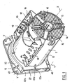
- FIGS. 1 and 2 show an alternator 1 comprising a metal casing 2 and a cover 3 attached to the casing 2.
- the alternator 1 is intended, in the example in question, to be fixed on a heat engine, not shown, to form a generator.
- the cover 3 which can be made of metal or plastic houses, for example, a conventional electrical circuit not visible in the figures, regulating and connecting the alternator.
- the alternator 1 comprises, as can be seen in Figure 2, inside the housing 3, a stator 4 and a rotor 5 rotatable inside the stator 4 about a geometric axis of rotation X.
- the rotor 5 comprises a shaft 6 on which is fixed a magnetic carcass 7 receiving inductor coils 8.
- the rotor 5 rotates a fan 9 for generating a cooling air stream.
- the housing 2 comprises a cylindrical body of revolution 12, which is connected at a first longitudinal end, by an enlarged portion 20, to a flange 13 serving for the fixing the alternator on the engine, via a connecting member, as will be specified in the following.
- the flange 13 has holes 40 each of Y axis, which are located radially outside the casing of the cylindrical body 12.
- the housing 2 also comprises, at a second longitudinal end opposite the first, a perforated transverse wall 14 and a bearing 15 for supporting the rotor shaft.
- Reinforcing ribs 16 extend radially between the bearing 15 and the cylindrical body 12.
- the flange 13 and the bearing 15 are made in one piece with the rest of the housing, by aluminum casting in the example.
- FIGS. 1 and 3 show in particular that the casing 2 comprises in the upper part two lateral extensions 18, extending over the major part of the cylindrical body 12, on which the cover 3 rests, these extensions 18 being each provided with a a plurality of openings 19 allowing an air intake under the hood, as will be specified below.
- the enlarged portion 20 which is made in one piece with the rest of the housing defines a housing for the fan 9.
- Two lateral openings 21 are formed in the enlarged portion 20 to allow the exit of the cooling air. Only one of these openings is apparent in Figures 1 and 3. Protection bars 22 are present in each opening 21 to protect the staff from contact with the fan in operation.
- the bars 22 are made in one piece with the housing 2, by casting. Before machining, the bars 22 are connected on the inner side by a web of material from the foundry.
- the casing 2 undergoes, after molding and fixing the stator, a machining intended in particular to produce a cylindrical surface of revolution about the axis X inside the bearing 15 to receive a cage 11 containing support bearings of the rotor shaft.
- the radially inner side of the bars 22 is machined to remove the aforementioned haze. This machining takes place in a single pass, to avoid a second pass that would be likely to damage the bars 22.
- ribs 41 project on the radially inner surface of the cylindrical body 12, for fixing the stator.
- the ribs 41 are made by molding with sufficient precision not to have to undergo machining.
- the transverse wall 14 has openings 43 to allow a cooling air inlet into the housing.
- the bars 22 each have a longitudinal axis Z which extends, as can be seen in particular in Figure 3, parallel to a plane perpendicular to the geometric axis X of rotation of the rotor, or substantially vertically in the example.
- the Z axis is non-rectilinear, the bars 22 each having a curved central portion 22a having a concave inner side towards the X axis.
- the bars 22 are connected at their longitudinal ends to the remainder of the casing 2 and are missing, along their length, between their longitudinal ends, connections between them.
- the grids formed by the bars 22 are therefore devoid of horizontal bars in the example under consideration. This arrangement reduces the pressure drop across openings 21 and improve the efficiency of ventilation.
- the widened portion 20 defines two passages 91 in the form of a volute. These two passages 91 are, in the example under consideration, substantially the image of one another by an axial symmetry of axis X.
- Each passage 91 has a section for the passage of air that increases as it approaches the exit.
- Each passage 91 comprises an enlarged portion 91a adjacent to a portion 22b of the bars 22.
- This portion 22b is connected at one end to the casing 2 and at the other end to the corresponding central portion 22a and forms with the latter a concavity facing the 'outside. This makes it possible to have the connecting portion 22b directed substantially perpendicularly to the direction of flow of the air.
- the bars 22 are two in number by lateral opening 21, in the example considered, but this number could, of course, be different.
- the casing 2 comprises, in the upper part, as can be seen in the figure 4, a first opening 24 intended to allow fixing inside the housing of a brush holder 30, shown schematically in Figures 7 and 8.
- the casing 2 also comprises, in the upper part, a second opening 25 intended to allow, with the opening 24, a circulation of cooling air and the passage of the electrical conductors of the stator.
- the brush holder 30 comprises on the one hand a support portion 31, on which are fixed conventional brushes 32, also called “brushes”, intended to come into contact with one end 32a. , with rings 110 of the rotor collector, also called “slip rings”, and secondly an attachment portion 33, intended to engage in a slideway 35 formed on the inner face of the transverse wall 14 of the casing 2 and with it, this slide 35 being vertical in the example in question.
- the brushes 32 are connected to tabs 32b for connecting the electrical conductors for supplying the rotor, not shown.
- a groove 39 is formed between the support portions 31 and fastening 33 to cooperate with returns 36 of the slideway 35.
- the fixing portion 33 has an extension 37 provided with a hole 38 for the passage of an immobilizing screw intended to engage in the transverse wall 14.
- the brush holder comprises stiffening webs 31a and 33a respectively associated with the support and fastening portions 33 and which extend substantially parallel to a plane containing the geometric axis of rotation X and coinciding with the section plane of the figure 2.
- the support portions 31 and attachment 33 are made in the example described in one piece by molding of insulating plastic material.
- the brush holder 30 is fixed on the casing 2 by being first introduced through the first opening 24 inside the casing 11, then sliding the fixing portion 33 in the slideway 35, then the brush holder 30. is immobilized axially in the slideway 35 by means of a screw inserted into the hole 38 and cooperating with the transverse wall 14.
- This connecting member 120 comprises a plate 130 through which a central opening 121 to allow the passage of the end of the rotor shaft to be coupled with the shaft of the engine.
- the plate 130 comprises a first set of holes 122 intended to allow its attachment to the heat engine and a second set of holes 123 intended to allow the fixing of the flange 13 of the alternator.
- nuts 125 are welded to the plate 120 opposite each hole 123, on the side intended to face the heat engine.
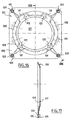
- FIG. 17 shows that the plate 120 is non-planar, and that it may comprise stiffening ribs 131.
- the plate 120 has a first flat surface 126 in the vicinity of its outer periphery, designed to bear against the flange 13 of the housing 2, and a second flat surface 127 bordering the opening 121 and intended to bear against the engine. Both surfaces 126 and 127 are axially offset by a greater distance than the thickness of the nuts 125.
- Projections 128 are intended to cooperate with the housing, being for example welded to the plate 130, in order to contribute to the centering of the connecting member on the alternator.
Abstract
Description
La présente invention concerne les machines électriques tournantes, et plus particulièrement mais non exclusivement, les alternateurs destinés aux groupes électrogènes et d'une puissance allant par exemple de quelques kilowatts à quelques dizaines de kilowatts, par exemple inférieure à 30 kW.The present invention relates to rotating electrical machines, and more particularly but not exclusively, alternators for generators and a power ranging for example from a few kilowatts to a few tens of kilowatts, for example less than 30 kW.
La demande EP-A2-1 081 828 décrit un alternateur comportant un rotor entraînant un ventilateur. Ce ventilateur tourne dans un logement définissant deux passages chacun en forme de volute, pour la sortie de l'air brassé par le ventilateur. Chaque passage offre une section croissante à l'air gagnant la sortie. Le logement précité est défini par une pièce rapportée sur le corps cylindrique du carter. D'une manière générale, les performances électriques d'un alternateur dépendent de l'efficacité du refroidissement et il est souhaitable que celle-ci soit la plus élevée possible.Application EP-A2-1 081 828 describes an alternator comprising a rotor driving a fan. This fan rotates in a housing defining two passages each volute-shaped, for the output of the air stirred by the fan. Each passage offers an increasing section to the air gaining the exit. The aforementioned housing is defined by an insert on the cylindrical body of the housing. In general, the electrical performance of an alternator depends on the efficiency of the cooling and it is desirable that it be as high as possible.
La demande japonaise JP 08223853 a pour objet un générateur comportant un rotor et un stator logés dans un carter composé d'une première pièce en forme de bol comportant des orifices de sortie d'air et d'une deuxième pièce comportant des orifices d'entrée d'air, les première et deuxième pièces étant rattachées l'une à l'autre par des vis.The Japanese application JP 08223853 relates to a generator comprising a rotor and a stator housed in a housing composed of a first bowl-shaped part having air outlet orifices and a second part having inlet orifices. of air, the first and second parts being attached to each other by screws.
On connaît aussi des alternateurs pour groupe électrogène, comportant :
- un carter de forme allongée,
- un rotor ayant un arbre pouvant tourner à l'intérieur du carter autour d'un axe géométrique de rotation,
- un ventilateur entraîné en rotation par le rotor.
- an elongated housing,
- a rotor having a shaft rotatable inside the housing about a geometric axis of rotation,
- a fan rotated by the rotor.
Dans ces alternateurs connus, les grilles de protection des ouvertures d'entrée et de sortie d'air sont constituées par des pièces indépendantes, ce qui implique des opérations d'assemblage sur le carter lors de la fabrication de l'alternateur et augmente le prix de revient de celui-ci.In these known alternators, the protection grids of the inlet and outlet openings are constituted by independent parts, which involves assembly operations on the housing during the manufacture of the alternator and increases the price of return of this one.
En outre, cela peut rendre la fixation de certains alternateurs sur le moteur thermique relativement fastidieuse, lorsque l'accès aux éléments de fixation s'effectue à travers les ouvertures par lesquelles l'air de refroidissement sort. Les grilles de protection doivent être enlevées pour permettre l'accès aux éléments de fixation, puis remises en place ensuite.In addition, this may make the attachment of some alternators on the engine relatively tedious, when access to the fasteners is through the openings through which the cooling air exits. Protective grilles must be removed to allow access to the fasteners and then put back in place.
On connaît aussi des alternateurs pour groupe électrogène, comportant :
- un carter de forme allongée
- un rotor ayant un arbre pouvant tourner à l'intérieur du carter autour d'un axe géométrique de rotation,
- au moins une bride de fixation de l'alternateur à une extrémité.
- an elongated housing
- a rotor having a shaft rotatable inside the housing about a geometric axis of rotation,
- at least one mounting flange of the alternator at one end.
La fixation de certains alternateurs de ce type sur le moteur thermique est relativement fastidieuse, car l'accès aux éléments de fixation s'effectue à travers les ouvertures par lesquelles l'air de refroidissement sort.The fixing of some alternators of this type on the engine is relatively tedious, because access to the fasteners is through the openings through which the cooling air exits.
Il existe un besoin pour disposer d'un alternateur ayant un coût de fabrication réduit tout en offrant des performances électriques et une fiabilité satisfaisantes.There is a need for an alternator having a reduced manufacturing cost while providing satisfactory electrical performance and reliability.
Il existe également un besoin pour faciliter la circulation de l'air destiné au refroidissement de la machine.There is also a need to facilitate the circulation of air for cooling the machine.
Il existe encore un besoin pour disposer d'une machine électrique, notamment un alternateur, dans lequel le montage ou le démontage du porte-balais soit facilité.There is still a need for an electric machine, including an alternator, in which the assembly or disassembly of the brush holder is facilitated.
La présente invention vise notamment à répondre à tout ou partie de ces besoins.The present invention aims in particular to meet all or part of these needs.
Selon un premier de ses aspects, l'invention a pour objet une machine tournante électrique comportant :
- un carter de forme allongée,
- un rotor ayant un arbre pouvant tourner à l'intérieur du carter autour d'un axe géométrique de rotation,
- un ventilateur entraîné en rotation par le rotor,
- an elongated housing,
- a rotor having a shaft rotatable inside the housing about a geometric axis of rotation,
- a fan driven in rotation by the rotor,
On évite ainsi d'avoir à rapporter sur le carter les grilles de protection des alternateurs connus, ce qui permet de diminuer le temps de main d'oeuvre nécessaire à la fabrication de l'alternateur.This avoids having to report on the housing the protective grids of known alternators, which reduces the labor time required for the manufacture of the alternator.
Dans un exemple de mise en oeuvre de l'invention, le carter est réalisé par fonderie, notamment en aluminium injecté.In an exemplary implementation of the invention, the housing is made by casting, in particular injected aluminum.
Le carter peut comporter, à une première extrémité longitudinale, une bride et à une deuxième extrémité longitudinale, opposée à la première, une paroi d'extrémité réalisée d'une seule pièce avec le carter et qui est ajourée pour former une grille pour l'entrée de l'air de refroidissement dans le carter.The housing may comprise, at a first longitudinal end, a flange and at a second longitudinal end, opposite to the first, an end wall formed integrally with the housing and which is perforated to form a grid for the intake of cooling air into the crankcase.
Cette paroi d'extrémité peut comporter, sur sa face intérieure, un relief permettant la fixation d'un porte-balais. Le relief précité peut comporter une glissière et le porte-balais peut être configuré pour coulisser dans cette glissière lors de son montage dans le carter. Une telle configuration facilite le montage du porte-balais et permet de réduire encore la durée de fabrication de l'alternateur. Le démontage du porte-balais, lors d'une opération d'entretien, s'en trouve lui aussi facilité.This end wall may comprise, on its inner face, a relief for fixing a brush holder. The aforementioned relief may include a slide and the brush holder may be configured to slide in this slide during its mounting in the housing. Such a configuration facilitates the mounting of the brush holder and reduces still the manufacturing time of the alternator. Disassembly of the brush holder, during a maintenance operation, is also facilitated.
Le carter peut, dans une réalisation particulière, comporter deux grilles latérales réalisées d'une seule pièce avec le carter et situées respectivement sur les côtés gauche et droit du carter lorsque l'alternateur est observé selon l'axe géométrique de rotation du rotor.The housing may, in a particular embodiment, comprise two lateral grids made in one piece with the housing and located respectively on the left and right sides of the housing when the alternator is observed along the geometric axis of rotation of the rotor.
Le carter peut comporter au moins un passage en forme de volute débouchant sur une grille latérale, et notamment deux passages en forme de volute respectivement associés aux deux grilles latérales précitées.The housing may comprise at least one volute-shaped passage opening on a side gate, and in particular two volute-shaped passages respectively associated with the two aforementioned lateral grids.
Ces passages en forme de volute peuvent être réalisés lors du moulage du carter, ce qui évite des opérations d'assemblage ultérieures.These volute-shaped passages can be made during the molding of the housing, which avoids subsequent assembly operations.
Une grille latérale au moins peut comporter des barreaux ayant chacun un axe longitudinal, de préférence curviligne, avec une portion concave vers le ventilateur. Chaque barreau peut être orienté sensiblement parallèlement à un plan perpendiculaire à l'axe géométrique de rotation du rotor. Les barreaux peuvent ainsi être sensiblement parallèles à un plan vertical, lorsque l'axe géométrique de rotation du rotor est horizontal.At least one lateral grid may comprise bars each having a longitudinal axis, preferably curvilinear, with a concave portion towards the fan. Each bar can be oriented substantially parallel to a plane perpendicular to the geometric axis of rotation of the rotor. The bars can thus be substantially parallel to a vertical plane, when the geometric axis of rotation of the rotor is horizontal.
Selon un autre aspect de l'invention, chaque grille latérale peut être dépourvue de barreaux s'étendant sensiblement parallèlement à l'axe géométrique de rotation du rotor, ce qui permet de diminuer la perte de charge subie par l'air à la traversée de la grille et d'améliorer ainsi le rendement du ventilateur et l'efficacité du refroidissement.According to another aspect of the invention, each lateral grid may be devoid of bars extending substantially parallel to the geometric axis of rotation of the rotor, which makes it possible to reduce the pressure drop experienced by the air at the crossing of the grid and thus improve the efficiency of the fan and the cooling efficiency.
Pour faciliter la réalisation des barreaux de la grille, ces derniers peuvent être moulés avec un voile de matière qui les relient sur leur côté radialement intérieur. Ce voile qui peut présenter une épaisseur relativement faible permet de renforcer la tenue mécanique des barreaux lors du refroidissement de la matière suite au moulage. Ce voile est éliminé lors d'une opération d'usinage de la surface intérieure du carter à sa sortie de la fonderie. Avantageusement, le procédé de fabrication du carter comporte l'étape consistant, après le moulage du carter, à éliminer progressivement par usinage en une seule passe, le voile qui s'étend entre les barreaux. Une deuxième passe, qui risquerait d'endommager les barreaux, est évitée.To facilitate the realization of the bars of the grid, they can be molded with a web of material which connect them on their radially inner side. This web, which may have a relatively small thickness, makes it possible to reinforce the mechanical strength of the bars during the cooling of the material following molding. This web is removed during a machining operation of the inner surface of the casing at its exit from the foundry. Advantageously, the process of manufacturing the housing comprises the step of, after molding the housing, to gradually eliminate machining in a single pass, the web that extends between the bars. A second pass, which could damage the bars, is avoided.
On peut usiner l'intérieur du carter lorsque le stator est déjà en place dans celui-ci, de façon à assurer plus facilement la concentricité des surfaces usinées.The inside of the casing can be machined when the stator is already in place therein, so as to more easily ensure the concentricity of the machined surfaces.
Le carter peut comporter des extensions de support d'un capot de protection d'un circuit électrique, notamment un circuit électrique de régulation et de raccordement de l'alternateur, ces extensions comportant des ouvertures d'entrée d'air. Le carter peut comporter au moins une ouverture débouchant sous le capot, pour permettre une aspiration de l'air sous celui-ci, durant le fonctionnement de l'alternateur. L'augmentation du rendement du ventilateur, grâce notamment aux grilles latérales dépourvues de barreaux parallèles à l'axe géométrique de rotation du rotor et à la présence des passages en forme de volute, permet d'obtenir un débit d'air de refroidissement, sous le capot, relativement important.The housing may have support extensions of a protective cover an electrical circuit, including an electrical circuit regulating and connecting the alternator, these extensions having air inlet openings. The housing may comprise at least one opening opening under the hood, to allow suction of air under it, during the operation of the alternator. The increase in the efficiency of the fan, thanks in particular to the side grids without bars parallel to the geometrical axis of rotation of the rotor and to the presence of the volute-shaped passages, makes it possible to obtain a flow of cooling air, under the hood, relatively important.
Le carter peut comporter des nervures axiales non usinées sur lesquelles repose le stator. Le fait que ces nervures soient non usinées permet de diminuer encore le coût de fabrication, en évitant une opération d'usinage spécifique.The casing may comprise unmachined axial ribs on which the stator rests. The fact that these ribs are unmachined makes it possible to further reduce the manufacturing cost, by avoiding a specific machining operation.
Le carter peut comporter un corps cylindrique et la bride peut comporter des passages pour des éléments de fixation ayant des axes situés radialement à l'extérieur de l'enveloppe du corps cylindrique. On peut ainsi avoir facilement accès aux éléments de fixation servant à fixer l'alternateur sur un moteur thermique, par exemple, sans avoir à procéder à un démontage des grilles de protection.The casing may comprise a cylindrical body and the flange may comprise passages for fastening elements having axes located radially outside the casing of the cylindrical body. It is thus easy to have access to fixing elements used to fix the alternator on a heat engine, for example, without having to disassemble the protective grilles.
L'invention a encore pour objet, selon un autre de ses aspects, indépendamment ou en combinaison avec ce qui précède, une machine électrique tournante comportant :
- un carter,
- un rotor pouvant tourner à l'intérieur du carter autour d'un axe géométrique de rotation,
- un ventilateur fixé sur le rotor,
- au moins une grille de sortie de l'air brassé par le ventilateur,
- a housing,
- a rotor rotatable inside the housing around a geometrical axis of rotation,
- a fan attached to the rotor,
- at least one air outlet grille blown by the fan,
A la différence des machines connues, comportant des grilles rapportées sur le carter, ces grilles comprenant un grand nombre de barreaux perpendiculaires entre eux, dans l'invention au moins l'une des grilles est dépourvue de barreaux sensiblement parallèles à l'axe géométrique de rotation ou en comporte un nombre relativement faible.Unlike known machines, having grids attached to the housing, these grids comprising a large number of bars perpendicular to each other, in the invention at least one of the grids is devoid of bars substantially parallel to the geometric axis of rotation or has a relatively small number.
Il en résulte que la perte de charge subie par l'air à la traversée de la grille est plus faible que si la grille comportait un nombre important de barreaux s'étendant sensiblement parallèlement à l'axe géométrique de rotation du rotor. Les barreaux peuvent ainsi être réalisés avec une section transversale plus importante pour une perte de charge équivalente, ce qui peut faciliter leur réalisation par fonderie d'un seul tenant avec le carter.As a result, the pressure drop experienced by the air through the gate is smaller than if the grid had a large number of bars extending substantially parallel to the geometric axis of rotation of the rotor. The bars can thus be made with a larger cross section for an equivalent pressure drop, which can facilitate their realization by casting in one piece with the housing.
De préférence, la grille est dépourvue de barreaux s'étendant sensiblement parallèlement à l'axe géométrique de rotation du rotor.Preferably, the gate is devoid of bars extending substantially parallel to the geometric axis of rotation of the rotor.
Le carter peut comporter des passages pour la sortie de l'air qui présentent une section offerte à la circulation de l'air qui augmente en se rapprochant de la sortie. Ces passages peuvent être en forme de volute, par exemple.The housing may include passages for the outlet of the air which have a section offered to the air circulation which increases as it approaches the exit. These passages can be volute-shaped, for example.
L'air peut sortir radialement.The air can come out radially.
Les barreaux de la grille peuvent être réalisés d'une seule pièce avec le carter, comme évoqué plus haut.The bars of the grid can be made in one piece with the housing, as mentioned above.
Les barreaux peuvent présenter une partie centrale ayant un axe longitudinal curviligne, concave vers le ventilateur. Cette partie centrale peut se raccorder au carter par une portion de raccordement formant avec la portion centrale une concavité tournée vers l'extérieur. Cette partie de raccordement peut être adjacente à une portion élargie du passage pour la sortie de l'air.The bars may have a central portion having a curvilinear longitudinal axis, concave towards the fan. This central portion can be connected to the housing by a connecting portion forming with the central portion a concavity facing outwardly. This connecting portion may be adjacent to an enlarged portion of the passage for the outlet of the air.
Les barreaux de la grille peuvent présenter un côté intérieur usiné.The bars of the grid may have a machined inner side.
La grille peut comporter deux barreaux.The grid may comprise two bars.
Le carter peut comporter, à une extrémité, une paroi transversale ajourée permettant l'aspiration de l'air, et le carter peut comporter un corps cylindrique pourvu d'une ouverture débouchant sous un capot de protection, des extensions sur lesquelles le capot vient en appui étant par ailleurs réalisées sur le carter, ces extensions étant pourvues d'ouvertures, l'air étant aspiré lors du fonctionnement du ventilateur par la paroi transversale ajourée, par les ouvertures des extensions et par l'ouverture réalisée sur le corps cylindrique du carter et refoulé par deux grilles de sortie de l'air telles que définies plus haut.The casing may comprise, at one end, a perforated transverse wall allowing the air to be drawn in, and the casing may comprise a cylindrical body provided with an opening opening under a protective cover, extensions on which the cover comes into support being also performed on the housing, these extensions being provided with openings, the air being sucked during operation of the fan by the perforated transverse wall, by the openings of the extensions and by the opening made on the cylindrical body of the housing and discharged by two air outlet grids as defined above.
L'invention a encore pour objet, selon un autre de ses aspects, indépendamment ou en combinaison avec ce qui précède, un ensemble comportant un alternateur et un organe de liaison permettant de fixer l'alternateur sur un moteur thermique, l'alternateur comportant un carter ayant un corps cylindrique et une bride, l'ensemble pouvant se caractériser par le fait que la bride comporte des passages pour des éléments de fixation de l'alternateur sur l'organe de liaison, ces passages ayant des axes situés à l'extérieur de l'enveloppe du corps cylindrique du carter, l'organe de liaison comportant un premier ensemble de trous pour la fixation de l'organe de liaison sur le moteur thermique et un deuxième ensemble de trous disposés de manière à se superposer aux passages de la bride, pour la fixation de l'alternateur sur l'organe de liaison.The invention further relates, in another of its aspects, independently or in combination with the above, an assembly comprising an alternator and a connecting member for fixing the alternator on an engine thermal generator, the alternator comprising a casing having a cylindrical body and a flange, the assembly being characterized in that the flange comprises passages for fastening elements of the alternator on the connecting member, these passages having axes located outside the casing of the cylindrical body of the casing, the connecting member comprising a first set of holes for fixing the connecting member on the heat engine and a second set of holes arranged so to be superimposed on the passages of the flange, for fixing the alternator on the connecting member.
Grâce à l'utilisation d'un tel organe de liaison, la fixation de l'alternateur sur le moteur thermique est facilitée et l'on peut éviter, par exemple, d'avoir à accéder à des éléments de fixation à travers des ouvertures de sortie de l'air de refroidissement de l'alternateur. Il peut ne plus être nécessaire de prévoir des grilles de protection amovibles et le carter peut comporter des barreaux s'étendant dans les ouvertures de sortie de l'air, réalisés d'une seule pièce avec le carter, par fonderie par exemple.Through the use of such a connecting member, the fixing of the alternator on the engine is facilitated and it can be avoided, for example, to have access to fasteners through openings of alternator cooling air outlet. It may no longer be necessary to provide removable protective grids and the housing may comprise bars extending into the air outlet openings, made in one piece with the housing, for example by casting.
L'organe de liaison peut comporter des écrous fixés sur une face d'une plaque, cette face pouvant être située en regard du moteur thermique, ces écrous pouvant être destinés à recevoir des vis introduites à travers des trous du deuxième ensemble de trous.The connecting member may comprise nuts fixed on a face of a plate, this face may be located opposite the heat engine, these nuts being able to receive screws introduced through holes of the second set of holes.
L'organe de liaison peut comporter une première portion annulaire plane sur laquelle sont réalisés les trous du premier ensemble de trous et une deuxième portion annulaire plane sur laquelle sont réalisés les trous d'un deuxième ensemble de trous, la deuxième portion annulaire étant décalée axialement par rapport à la première portion annulaire.The connecting member may comprise a first flat annular portion on which are formed the holes of the first set of holes and a second flat annular portion on which are formed the holes of a second set of holes, the second annular portion being offset axially. relative to the first annular portion.
Le décalage entre les première et deuxième portions annulaires peut être supérieur à l'épaisseur des écrous.The offset between the first and second annular portions may be greater than the thickness of the nuts.
L'organe de liaison peut comporter des nervures de renforcement.The connecting member may comprise reinforcing ribs.
L'organe de liaison peut comporter des parties saillantes, en forme de portions de cercle destinées à coopérer avec le carter de l'alternateur, pour contribuer au centrage de l'organe de liaison sur l'alternateur.The connecting member may comprise projecting portions, in the form of circular portions intended to cooperate with the alternator housing, to contribute to the centering of the connecting member on the alternator.
La bride de l'alternateur peut être réalisée d'une seule pièce avec le carter.The alternator flange can be made in one piece with the housing.
L'invention a encore pour objet, selon un autre de ses aspects, indépendamment ou en combinaison avec ce qui précède, un groupe électrogène comportant un alternateur et un moteur thermique, ce groupe pouvant se caractériser par le fait que l'alternateur est fixé sur le moteur thermique par l'intermédiaire d'un organe de liaison.The invention further relates, in another of its aspects, independently or in combination with the foregoing, a generator comprising an alternator and a heat engine, this group being characterized by the fact that the alternator is fixed on the heat engine through an organ of link.
Cet organe de liaison peut être configuré pour permettre, dans un premier temps, sa fixation sur le moteur thermique et, dans un deuxième temps, la fixation de l'alternateur sur l'organe de liaison.This connecting member may be configured to allow, at first, its attachment to the engine and, in a second step, the attachment of the alternator on the connecting member.
L'organe de liaison peut comporter des trous permettant sa fixation sur le moteur thermique et des écrous pour recevoir des vis de fixation de l'alternateur sur l'organe de liaison.The connecting member may comprise holes for fixing it to the heat engine and nuts to receive the fixing screws of the alternator on the connecting member.
L'invention a encore pour objet, selon un autre de ses aspects, indépendamment ou en combinaison avec ce qui précède, un organe de liaison pour fixer un alternateur sur un moteur thermique, comportant :
- une plaque pourvue d'une ouverture permettant l'accouplement d'un arbre du rotor de l'alternateur avec le moteur thermique,
- un premier ensemble de trous pour la fixation de la plaque sur le moteur thermique,
- un deuxième ensemble de trous situés radialement à l'extérieur des premiers, pour la fixation de l'alternateur sur la plaque.
- a plate provided with an opening for coupling a rotor shaft of the alternator with the heat engine,
- a first set of holes for fixing the plate on the heat engine,
- a second set of holes located radially outside the first, for fixing the alternator on the plate.
L'invention a encore pour objet, selon un autre de ses aspects, indépendamment ou en combinaison avec ce qui précède, une machine électrique tournante comportant un stator et un rotor pouvant tourner autour d'un axe géométrique de rotation à l'intérieur du stator, le rotor comportant une carcasse sur laquelle sont disposés des bobinages et des cales de maintien des bobinages, au moins une cale définissant, lorsque observée en section dans un plan perpendiculaire à l'axe géométrique de rotation, une concavité ouverte vers le stator.The invention further relates, in another of its aspects, independently or in combination with the foregoing, to a rotating electrical machine comprising a stator and a rotor rotatable about a geometrical axis of rotation inside the stator , the rotor comprising a carcass on which are arranged windings and holds for holding the windings, at least one shim defining, when observed in section in a plane perpendicular to the geometric axis of rotation, an open concavity towards the stator.
La présence d'une telle concavité facilite le passage de l'air de refroidissement, de sorte que le refroidissement de la machine est amélioré.The presence of such a concavity facilitates the passage of cooling air, so that the cooling of the machine is improved.
L'invention a encore pour objet, selon un autre de ses aspects, indépendamment ou en combinaison avec ce qui précède, une machine tournante électrique comportant :
- un rotor pouvant tourner autour d'un axe géométrique de rotation, ce rotor comprenant :
- une carcasse magnétique comportant des encoches recevant des bobinages et,
- des amortisseurs comportant des conducteurs électriques traversant des passages correspondants de la carcasse magnétique,
- a rotor rotatable about a geometrical axis of rotation, said rotor comprising:
- a magnetic carcass having slots receiving coils and,
- dampers comprising electrical conductors passing through corresponding passages of the magnetic carcass,
Grâce à cette disposition des passages, l'atténuation des harmoniques et/ou la circulation du flux magnétique peut être améliorée.Thanks to this arrangement of the passages, harmonic attenuation and / or magnetic flux circulation can be improved.
L'écartement entre deux passages consécutifs, lorsque l'on se déplace circonférentiellement autour de l'axe géométrique de rotation du rotor d'un côté d'un plan médian, peut être non constant. En particulier, cet écartement peut varier, par exemple de manière monotone, et augmenter lorsque l'on se déplace circonférentiellement dans le sens de rotation du rotor. Cela peut permettre d'améliorer le fonctionnement de la machine, en charge notamment.The spacing between two consecutive passages, when one moves circumferentially around the geometric axis of rotation of the rotor on one side of a median plane, may be non-constant. In particular, this spacing may vary, for example in a monotonous manner, and increase when one moves circumferentially in the direction of rotation of the rotor. This can improve the operation of the machine, especially in charge.
Selon un autre aspect de l'invention, au moins un passage peut présenter une section transversale non circulaire. En particulier, au moins un passage peut présenter une section transversale oblongue, ayant un axe de plus grande dimension orienté sensiblement radialement. Une telle disposition peut faciliter le passage du flux.According to another aspect of the invention, at least one passage may have a non-circular cross section. In particular, at least one passage may have an oblong cross section, having an axis of larger dimension oriented substantially radially. Such an arrangement may facilitate the passage of the stream.
L'invention a encore pour objet, indépendamment ou en combinaison avec ce qui précède, une machine électrique tournante, comportant :
- un carter,
- un rotor pouvant tourner à l'intérieur du carter,
- un porte-balais comportant des balais configurés pour venir en contact électrique avec le rotor,
- a housing,
- a rotor rotatable inside the housing,
- a brush holder comprising brushes configured to come into electrical contact with the rotor,
Une telle configuration facilite le montage du porte-balais et permet de réduire la durée de fabrication de la machine.Such a configuration facilitates the mounting of the brush holder and reduces the manufacturing time of the machine.
Le porte-balais est configuré pour pouvoir coulisser dans la glissière lors de son montage dans le carter. Le démontage du porte-balais, lors d'une opération d'entretien, s'en trouve lui aussi facilité.The brush holder is configured to slide in the slide when mounted in the housing. Disassembly of the brush holder, during a maintenance operation, is also facilitated.
La glissière peut également permettre, le cas échéant, de positionner radialement le porte-balais, relativement à l'arbre du rotor.The slide can also allow, if necessary, to position radially the brush holder, relative to the rotor shaft.
La paroi transversale peut être située à une extrémité longitudinale du carter, et peut être traversée, par exemple, par une pluralité d'ouvertures d'entrée d'air.The transverse wall may be located at a longitudinal end of the housing, and may be traversed, for example, by a plurality of air inlet openings.
Le carter peut comporter un corps cylindrique traversé par une ouverture, par exemple attenante à la glissière précitée, à travers laquelle peut s'effectuer la mise en place ou le démontage du porte-balais.The housing may comprise a cylindrical body traversed by an opening, for example adjacent to the aforementioned slide, through which can be carried out the introduction or removal of the brush holder.
Cette ouverture peut servir également à l'entrée d'air dans le carter, pour le refroidissement de celui-ci.This opening can also be used for the entry of air into the housing, for cooling thereof.
Le porte-balais peut être immobilisé dans la glissière par un élément de fixation tel que par exemple une vis introduite à travers une extension du porte-balais et vissée dans le carter. L'extension précitée peut être configurée pour permettre de régler légèrement la position radiale du porte-balais.The brush holder can be immobilized in the slideway by a fixing element such as for example a screw inserted through an extension of the brush holder and screwed into the housing. The aforementioned extension can be configured to allow a slight adjustment of the radial position of the brush holder.
Le porte-balais peut comporter des voiles de rigidification s'étendant parallèlement à un plan contenant l'axe géométrique de rotation du rotor.The brush holder may comprise stiffening webs extending parallel to a plane containing the geometrical axis of rotation of the rotor.
La machine peut constituer un alternateur, notamment pour groupe électrogène.The machine may constitute an alternator, in particular for a generator.
La glissière peut être orientée radialement.The slide can be oriented radially.
La machine peut comporter ou non des balais et un porte-balais. En l'absence de balais, les bobinages d'inducteur peuvent être reliés à des condensateurs.The machine may or may not have brushes and a brush holder. In the absence of brushes, the inductor coils can be connected to capacitors.
Les différents aspects de l'invention définis ci-dessus peuvent avantageusement être mis en oeuvre au sein d'une même machine, en particulier un alternateur, mais il peut également en être autrement et l'un de ces aspects peut être mis en oeuvre d'une manière indépendante.The various aspects of the invention defined above can advantageously be implemented within the same machine, in particular an alternator, but it can also be different and one of these aspects can be implemented in a single machine. an independent way.
L'invention pourra être mieux comprise à la lecture de la description qui va suivre, d'un exemple de mise en oeuvre non limitatif, et à l'examen du dessin annexé, sur lequel :
- la figure 1 représente, de manière schématique et en perspective, un exemple de carter d'alternateur réalisé conformément à l'invention,
- la figure 2 est une coupe axiale, partielle et schématique, d'un alternateur comportant le carter de la figure 1,
- la figure 3 représente isolément, en vue de côté, le carter de la figure 1,
- la figure 4 est une vue de dessus, schématique et partielle, selon la flèche IV de la figure 3,
- la figure 5 est une vue de face, schématique et partielle, avec arrachement, selon la flèche V de la figure 4,
- la figure 6 est une vue de face, schématique et partielle, selon la flèche VI de la figure 4,
- la figure 7 représente isolément, en coupe dans un plan médian, un porte-balais,
- la figure 8 est une vue de dessus, schématique et partielle, selon la flèche VIII de la figure 7,
- la figure 16 représente isolément, en vue de face, la pièce de liaison, et
- la figure 17 est une coupe selon XVII-XVII de la figure 16.
- FIG. 1 represents, schematically and in perspective, an example of an alternator housing made according to the invention,
- FIG. 2 is an axial section, partial and schematic, of an alternator comprising the casing of FIG. 1;
- FIG. 3 is a side view of the housing of FIG.
- FIG. 4 is a view from above, schematic and partial, along the arrow IV of FIG. 3,
- FIG. 5 is a front view, schematic and partial, with tearing, along the arrow V of FIG. 4,
- FIG. 6 is a front view, schematic and partial, along the arrow VI of FIG. 4,
- FIG. 7 represents, in isolation, in section in a median plane, a brush holder,
- FIG. 8 is a view from above, schematic and partial, along the arrow VIII of FIG. 7,
- FIG. 16 represents in isolation, in front view, the connecting piece, and
- Figure 17 is a section on XVII-XVII of Figure 16.
On a représenté aux figures 1 et 2 un alternateur 1 comportant un carter métallique 2 et un capot 3 rapporté sur le carter 2. L'alternateur 1 est destiné, dans l'exemple considéré, à être fixé sur un moteur thermique, non représenté, pour former un groupe électrogène. Le capot 3 qui peut être réalisé en métal ou en matière plastique abrite, par exemple, un circuit électrique conventionnel non apparent sur les figures, de régulation et de raccordement de l'alternateur.FIGS. 1 and 2 show an
L'alternateur 1 comporte, comme on peut le voir sur la figure 2, à l'intérieur du carter 3, un stator 4 et un rotor 5 pouvant tourner à l'intérieur du stator 4 autour d'un axe géométrique de rotation X.The
Le rotor 5 comporte un arbre 6 sur lequel est fixée une carcasse magnétique 7 recevant des bobinages d'inducteur 8.The
Le rotor 5 entraîne en rotation un ventilateur 9 destiné à générer un courant d'air de refroidissement.The
Le carter 2 comporte un corps cylindrique de révolution 12, qui se raccorde à une première extrémité longitudinale, par une partie élargie 20, à une bride 13 servant à la fixation de l'alternateur sur le moteur thermique, via un organe de liaison, comme cela sera précisé dans la suite.The
La bride 13 comporte des perçages 40 chacun d'axe Y, qui se situent radialement à l'extérieur de l'enveloppe du corps cylindrique 12.The
Le carter 2 comporte également, à une deuxième extrémité longitudinale opposée à la première, une paroi transversale ajourée 14 et un palier 15 de support de l'arbre du rotor.The
Des nervures 16 de renforcement s'étendent radialement entre le palier 15 et le corps cylindrique 12.Reinforcing
La bride 13 et le palier 15 sont réalisés d'un seul tenant avec le reste du carter, par fonderie d'aluminium dans l'exemple considéré.The
On voit sur les figures 1 et 3 notamment que le carter 2 comporte en partie supérieure deux extensions latérales 18, s'étendant sur la majeure partie du corps cylindrique 12, sur lesquelles repose le capot 3, ces extensions 18 étant pourvues chacune d'une pluralité d'ouvertures 19 permettant une entrée d'air sous le capot, comme cela sera précisé plus loin.FIGS. 1 and 3 show in particular that the
La partie élargie 20 qui est réalisée d'une seule pièce avec le reste du carter définit un logement pour le ventilateur 9.The
Deux ouvertures latérales 21 sont réalisées dans la partie élargie 20 pour permettre la sortie de l'air de refroidissement. L'une seulement de ces ouvertures est apparente sur les figures 1 et 3. Des barreaux de protection 22 sont présents dans chaque ouverture 21 pour protéger le personnel d'un contact avec le ventilateur en fonctionnement. Les barreaux 22 sont réalisés d'un seul tenant avec le carter 2, par fonderie. Avant usinage, les barreaux 22 sont liés du côté intérieur par un voile de matière venu de fonderie.Two
Le carter 2 subit, après son moulage et fixation du stator, un usinage destiné notamment à réaliser une surface cylindrique de révolution autour de l'axe X à l'intérieur du palier 15 pour recevoir une cage 11 contenant des roulements de support de l'arbre du rotor.The
Le côté radialement intérieur des barreaux 22 est usiné pour enlever le voile précité. Cet usinage a lieu en une seule passe, afin d'éviter une deuxième passe qui serait susceptible d'endommager les barreaux 22.The radially inner side of the
On voit sur la figure 5 que des nervures 41 forment saillie sur la surface radialement intérieure du corps cylindrique 12, pour la fixation du stator. Les nervures 41 sont réalisées par moulage avec suffisamment de précision pour ne pas avoir à subir d'usinage.It can be seen in FIG. 5 that
La paroi transversale 14 comporte des ajours 43 pour permettre une entrée d'air de refroidissement dans le carter.The
Les barreaux 22 présentent chacun un axe longitudinal Z qui s'étend, comme on peut le voir notamment sur la figure 3, parallèlement à un plan perpendiculaire à l'axe géométrique X de rotation du rotor, soit sensiblement verticalement dans l'exemple considéré. L'axe Z est non rectiligne, les barreaux 22 comportant chacun une portion centrale 22a curviligne ayant un côté intérieur concave vers l'axe X.The
On peut remarquer également, à l'examen de la figure 3, que les barreaux 22 se raccordent à leurs extrémités longitudinales au reste du carter 2 et sont dépourvus, sur leur longueur, entre leurs extrémités longitudinales, de liaisons entre eux. Les grilles formées par les barreaux 22 sont donc dépourvues, dans l'exemple considéré, de barreaux horizontaux. Cette disposition permet de diminuer la perte de charge à la traversée des ouvertures 21 et d'améliorer l'efficacité de la ventilation.It may also be noted, on examining FIG. 3, that the
On voit sur la figure 5 que la partie élargie 20 définit deux passages 91 en forme de volute. Ces deux passages 91 sont, dans l'exemple considéré, sensiblement l'image l'un de l'autre par une symétrie axiale d'axe X.It can be seen in FIG. 5 that the widened
Chaque passage 91 présente une section offerte au passage de l'air qui augmente en se rapprochant de la sortie.Each
Sur la figure 5, le ventilateur tourne dans le sens des aiguilles d'une montre.In Figure 5, the fan rotates in a clockwise direction.
Chaque passage 91 comporte une portion élargie 91a adjacente à une portion 22b des barreaux 22. Cette portion 22b se raccorde à une extrémité au carter 2 et à l'autre extrémité à la portion centrale 22a correspondante et forme avec cette dernière une concavité tournée vers l'extérieur. Cela permet d'avoir la portion de raccordement 22b dirigée sensiblement perpendiculairement à la direction d'écoulement de l'air.Each
Les barreaux 22 sont au nombre de deux par ouverture latérale 21, dans l'exemple considéré, mais ce nombre pourrait, bien entendu, être différent.The
Le carter 2 comporte, en partie supérieure, comme on peut le voir sur la figure 4, une première ouverture 24 destinée à permettre la fixation à l'intérieur du carter d'un porte-balais 30, représenté schématiquement sur les figures 7 et 8.The
Le carter 2 comporte également, en partie supérieure, une deuxième ouverture 25 destinée à permettre, avec l'ouverture 24, une circulation d'air de refroidissement et le passage des conducteurs électriques du stator.The
On voit sur les figures 7 et 8 que le porte-balais 30 comporte d'une part une partie de support 31, sur laquelle sont fixés des balais 32 conventionnels, encore appelés « brushes », destinés à venir en contact, par une extrémité 32a, avec des bagues 110 du collecteur du rotor, encore appelées « slip rings », et d'autre part une partie de fixation 33, destinée à s'engager dans une glissière 35 réalisée sur la face intérieure de la paroi transversale 14 du carter 2 et avec celui-ci, cette glissière 35 étant verticale dans l'exemple considéré. Les balais 32 sont reliés à des pattes 32b de raccordement des conducteurs électriques d'alimentation du rotor, non représentés.It can be seen in FIGS. 7 and 8 that the
Une gorge 39, est formée entre les parties de support 31 et de fixation 33 pour coopérer avec des retours 36 de la glissière 35.A
La partie de fixation 33 comporte une extension 37 pourvue d'un trou 38 pour le passage d'une vis d'immobilisation destinée à s'engager dans la paroi transversale 14.The fixing
Le porte-balais comporte des voiles de rigidification 31a et 33a associés respectivement aux parties de support 31 et de fixation 33 et qui s'étendent sensiblement parallèlement à un plan contenant l'axe géométrique de rotation X et confondu avec le plan de coupe de la figure 2.The brush holder comprises stiffening
Les parties de support 31 et de fixation 33 sont réalisées dans l'exemple décrit d'une seule pièce par moulage de matière plastique isolante.The
Le porte-balais 30 est fixé sur le carter 2 en étant d'abord introduit par la première ouverture 24 à l'intérieur du carter 11, en faisant coulisser ensuite la partie de fixation 33 dans la glissière 35, puis le porte-balais 30 est immobilisé axialement dans la glissière 35 grâce à une vis introduite dans le trou 38 et coopérant avec la paroi transversale 14.The
Dans l'exemple considéré, la fixation de l'alternateur sur le moteur s'effectue au moyen d'un organe de liaison 120 que l'on a représenté isolément sur les figures 16 et 17.In the example considered, the fixing of the alternator on the engine is carried out by means of a connecting
Cet organe de liaison 120 comporte une plaque 130 traversée par une ouverture centrale 121 pour permettre le passage de l'extrémité de l'arbre du rotor à accoupler avec l'arbre du moteur thermique.This connecting
La plaque 130 comporte un premier ensemble de trous 122 destinés à permettre sa fixation sur le moteur thermique et un deuxième ensemble de trous 123 destinés à permettre la fixation de la bride 13 de l'alternateur. Dans l'exemple illustré, des écrous 125 sont soudés sur la plaque 120 en regard de chaque trou 123, du côté destiné à faire face au moteur thermique.The
On voit sur la figure 17 que la plaque 120 est non plane, et qu'elle peut comporter des nervures de rigidification 131. La plaque 120 présente une première surface plane 126 dans le voisinage de sa périphérie extérieure, destinée à venir en appui contre la bride 13 du carter 2, et une deuxième surface plane 127 bordant l'ouverture 121 et destinée à venir en appui contre le moteur thermique. Les deux surfaces 126 et 127 sont décalées axialement d'une distance supérieure à l'épaisseur des écrous 125.FIG. 17 shows that the
Des parties saillantes 128 sont destinées à coopérer avec le carter, étant par exemple soudées sur la plaque 130, afin de contribuer au centrage de l'organe de liaison sur l'alternateur.
Pour fixer l'alternateur sur le moteur thermique, on commence par fixer la plaque 130 sur ce dernier, en introduisant des éléments de fixation tels que des vis dans les trous 122, puis l'alternateur peut être fixé sur la plaque 130 en introduisant des éléments de fixation tels que des vis dans les passages 40 et les trous 123.To fix the alternator on the heat engine, we first fix the
On remarquera que de par la disposition des passages 40 à l'extérieur de l'enveloppe du corps cylindrique 12, il est très facile de mettre en place les éléments de fixation du carter de l'alternateur sur l'organe de liaison 120. Les éléments de fixation peuvent être vissés par exemple au moyen d'une clé sans avoir à engager cette dernière au travers d'une ouverture de sortie d'air de refroidissement, contrairement aux alternateurs connus.It will be noted that, by the arrangement of the
Bien entendu, l'invention n'est pas limitée à l'exemple de réalisation qui vient d'être décrit.Of course, the invention is not limited to the embodiment which has just been described.
On peut notamment, sans sortir du cadre de la présente invention, réaliser le carter autrement.In particular, without departing from the scope of the present invention, the carter otherwise.
Dans toute la description, y compris les revendications, l'expression « comportant un » doit être comprise comme étant synonyme de « comportant au moins un », sauf si le contraire est spécifié.Throughout the description, including the claims, the phrase "having one" should be understood as being synonymous with "having at least one", unless the opposite is specified.
Claims (14)
- An electric rotary machine comprising:- a casing (2) of elongate shape;- a rotor having a shaft capable of turning inside the casing about an axis of rotation (X);- a fan (9) rotated by the rotor;machine characterized by the fact that the casing comprises at least one air inlet grid (14) and at least one air outlet grid (21,22), both of which are made integrally one with each other and with the casing.
- A machine according to claim 1, wherein the casing (2) is made as a casting, in particular out of injected aluminum.
- A machine according to the preceding claim, characterized by the fact that the casing (2) has a flange (13) at a first longitudinal end, and has a perforated end wall at a second longitudinal end opposite from the first, the end wall being made integrally with the casing and forming the air inlet grid (14).
- A machine according to claim 3, characterized by the fact that the flange (13) is made integrally with the casing.
- A machine according to any one of the two preceding claims, characterized by the fact that the end wall (14) comprises a portion in relief (35,36) on an inside face serving to fix a brush carrier (30).
- A machine according to the preceding claim, characterized by the fact that the portion in relief comprises a slideway (35,36), and by the fact that the brush carrier (30) is configured to be capable of sliding in the slideway while being mounted in the casing (2).
- A machine according to any one of the preceding claims, characterized by the fact that the casing has two side grids (21,22) made integrally with the casing and situated respectively on the left and right sides of the casing when the alternator is observed along the axis of rotation (X) of the rotor.
- A machine according to any one of preceding claims, characterized by the fact that the casing (2) comprises at least one volute (91) opening out to a grid (21,22).
- A machine according to any one of the preceding claims, characterized by the fact that the casing has at least one grid including bars (122), each having a longitudinal axis (2) extending substantially parallel to a plane perpendicular to the axis of rotation (X) of the rotor.
- A machine according to the preceding claim, characterized by the fact that the bars (22) present a radially inner side that is machined.
- A machine according to any one of the preceding claims, characterized by the fact that the casing comprises extensions (18) for supporting a cover (3), said extensions comprising air inlet openings (19), the casing having at least one opening opening (24,25) out to the inside of the cover to enable air to be sucked in beneath it when the alternator is in operation.
- A machine according to any one of the preceding claims, characterized by the fact that the casing comprises non-machined axial splines (41) against which a stator rests.
- A machine according to any of the preceding claims, characterized by the fact that the casing (2) comprises a cylindrical body (12) and a flange (13), the flange (13) having passages (40) for fixing elements having axes (Y) situated radially outside the envelope of the cylindrical body (12).
- A machine according to any one of the preceding claims, characterized by the fact that it constitutes an alternator.
Applications Claiming Priority (8)
| Application Number | Priority Date | Filing Date | Title |
|---|---|---|---|
| FR0208667A FR2842366A1 (en) | 2002-07-10 | 2002-07-10 | Rotary electrical machine, especially alternator, has casing with integral air intake and air outlet grilles in single piece construction |
| FR0208666A FR2842367A1 (en) | 2002-07-10 | 2002-07-10 | Rotary electrical machine, especially alternator, has casing with integral air intake and air outlet grilles in single piece construction |
| FR0208666 | 2002-07-10 | ||
| FR0208671 | 2002-07-10 | ||
| FR0208668 | 2002-07-10 | ||
| FR0208667 | 2002-07-10 | ||
| FR0208668A FR2842365B1 (en) | 2002-07-10 | 2002-07-10 | ALTERNATOR HAVING A MONOBLOCK HOUSING |
| FR0208671A FR2842368A1 (en) | 2002-07-10 | 2002-07-10 | Rotary electrical machine, especially alternator, has casing with integral air intake and air outlet grilles in single piece construction |
Publications (2)
| Publication Number | Publication Date |
|---|---|
| EP1383228A1 EP1383228A1 (en) | 2004-01-21 |
| EP1383228B1 true EP1383228B1 (en) | 2007-03-07 |
Family
ID=29783272
Family Applications (1)
| Application Number | Title | Priority Date | Filing Date |
|---|---|---|---|
| EP03291694A Expired - Lifetime EP1383228B1 (en) | 2002-07-10 | 2003-07-08 | Alternator with ventilation grills |
Country Status (5)
| Country | Link |
|---|---|
| US (1) | US20040051412A1 (en) |
| EP (1) | EP1383228B1 (en) |
| AT (1) | ATE356462T1 (en) |
| DE (1) | DE60312264D1 (en) |
| ES (1) | ES2283727T3 (en) |
Families Citing this family (6)
| Publication number | Priority date | Publication date | Assignee | Title |
|---|---|---|---|---|
| US7362017B2 (en) * | 2005-06-20 | 2008-04-22 | Reliance Electric Technologies, Llc | Motor with integrated drive unit and shared cooling fan |
| US9373986B2 (en) * | 2012-11-02 | 2016-06-21 | Rockwell Automation Technologies, Inc. | Method for providing servo motor rear bearing support, space for internal electronic packaging and IP sealing between motor and externally attached devices |
| FR3002822B1 (en) * | 2013-03-04 | 2017-04-14 | Moteurs Leroy-Somer | ELECTRIC MACHINE WITH COUPLING FLANGE. |
| GB2558171A (en) * | 2016-03-18 | 2018-07-11 | Cummins Generator Technologies | Adaptor with improved airflow |
| DE102016108233A1 (en) * | 2016-05-03 | 2017-11-09 | Ebm-Papst Mulfingen Gmbh & Co. Kg | Engine cradle |
| CN105971763B (en) * | 2016-07-01 | 2018-08-17 | 无锡雨德智能物联网科技有限公司 | A kind of engine housing with geomantic omen refrigerating function |
Family Cites Families (21)
| Publication number | Priority date | Publication date | Assignee | Title |
|---|---|---|---|---|
| BE374045A (en) * | ||||
| US926086A (en) * | 1905-08-21 | 1909-06-22 | Allis Chalmers | Dynamo-electric machine. |
| US2438872A (en) * | 1944-11-14 | 1948-03-30 | Singer Mfg Co | Dynamoelectric machine |
| DE1403052A1 (en) * | 1956-12-07 | 1969-01-30 | Firth Cleveland Ltd | Radial vane grille made of plastic |
| US3170079A (en) * | 1962-07-17 | 1965-02-16 | Eaton Mfg Co | Coupling apparatus |
| US3730642A (en) * | 1971-10-14 | 1973-05-01 | Vernco Corp | Cooling means for motor of a wet pick-up vacuum sweeper |
| US3748507A (en) * | 1971-12-02 | 1973-07-24 | Gen Electric | Variable speed drive having enhanced ventilation |
| US4118646A (en) * | 1975-07-29 | 1978-10-03 | Markon Engineering Company Limited | Electromagnetic machines |
| FI101841B1 (en) * | 1988-10-11 | 1998-08-31 | Schorch Gmbh | Electric engine |
| US4908538A (en) * | 1989-02-28 | 1990-03-13 | Geberth John Daniel Jun | Totally enclosed electric motor |
| US5182482A (en) * | 1991-05-15 | 1993-01-26 | Siemens Energy & Automation, Inc. | Dynamoelectric machine having improved ventilation |
| US5245237A (en) * | 1992-03-19 | 1993-09-14 | General Electric Company | Two compartment motor |
| JP2752297B2 (en) * | 1992-06-23 | 1998-05-18 | 株式会社日立製作所 | AC generator for vehicles |
| US5283490A (en) * | 1993-01-11 | 1994-02-01 | Marathon Electric Mfg. Corp. | Ventilating apparatus for dynamoelectric machine with animal restricted ventilating openings |
| FR2716309B1 (en) * | 1994-02-11 | 1996-04-19 | Leroy Somer | Brush holder for rotating electric machine. |
| FR2721452B1 (en) * | 1994-06-17 | 1996-09-06 | Leroy Somer Moteurs | Coiled stator with notches for a rotating electric machine, method for producing such a stator and machine comprising such a stator. |
| DE19617265A1 (en) * | 1996-02-10 | 1997-08-14 | Vorwerk Co Interholding | High-speed electric motor cooled by helical flow of external air e.g. for vacuum cleaner |
| US6133665A (en) * | 1998-08-14 | 2000-10-17 | S-B Power Tool Company | Brush system for electric motors |
| US6227822B1 (en) * | 1998-10-20 | 2001-05-08 | Lakewood Engineering And Manufacturing Co. | Fan with improved electric motor and mounting |
| US6144137A (en) * | 1998-12-02 | 2000-11-07 | Trw Inc. | Electric motor assembly for a vehicle steering system |
| JP2000270518A (en) * | 1999-03-17 | 2000-09-29 | Hitachi Ltd | Ac generator for vehicle |
-
2003
- 2003-07-07 US US10/613,075 patent/US20040051412A1/en not_active Abandoned
- 2003-07-08 DE DE60312264T patent/DE60312264D1/en not_active Expired - Lifetime
- 2003-07-08 EP EP03291694A patent/EP1383228B1/en not_active Expired - Lifetime
- 2003-07-08 AT AT03291694T patent/ATE356462T1/en not_active IP Right Cessation
- 2003-07-08 ES ES03291694T patent/ES2283727T3/en not_active Expired - Lifetime
Also Published As
| Publication number | Publication date |
|---|---|
| ES2283727T3 (en) | 2007-11-01 |
| DE60312264D1 (en) | 2007-04-19 |
| ATE356462T1 (en) | 2007-03-15 |
| EP1383228A1 (en) | 2004-01-21 |
| US20040051412A1 (en) | 2004-03-18 |
Similar Documents
| Publication | Publication Date | Title |
|---|---|---|
| FR2838253A1 (en) | ROTATING ELECTRIC MACHINE WITH FORCED VENTILATION | |
| FR2887698A1 (en) | HIGH-LEVEL ROTOR HAVING HOLDING FLASKS HAVING CONTACT SURFACES WITH COILS OF WINDINGS | |
| FR2791826A1 (en) | RECTIFIER ARRANGEMENT OF A VEHICLE ALTERNATING CURRENT GENERATOR | |
| EP2825770A1 (en) | Aerogenerator comprising a trunk and a plurality of branches extending from this trunk | |
| WO2004106748A1 (en) | Ventilation device, especially for a motor vehicle alternator | |
| EP1383228B1 (en) | Alternator with ventilation grills | |
| WO2014002071A1 (en) | Rotating electric machine provided with a terminal box | |
| EP3226388A2 (en) | Improved front flange of rotating electrical machine and rotating electrical machine comprising such a flange | |
| FR3003303A1 (en) | TURBOMACHINE, SUCH AS A TURBOJET OR AIRCRAFT TURBOPROPULSER | |
| FR2927737A1 (en) | ROTATING ELECTRIC MACHINE BEARING AND ROTATING ELECTRIC MACHINE COMPRISING SUCH A BEARING | |
| CH310612A (en) | Closed rotary electric machine. | |
| FR2770878A1 (en) | FAN WHEEL | |
| WO1999004480A1 (en) | Electric motor, in particular for motor vehicle, with improved cooling radiator | |
| WO2001047093A1 (en) | Foucault current retarder | |
| FR2498838A1 (en) | METHOD FOR COOLING AN OUTDOOR ROTOR ENGINE AND EXTERNALLY ROTOR ENGINE COOLED BY THE METHOD IN QUESTION | |
| FR2838252A1 (en) | Electric generator for a wind turbine having cooling fins perpendicular to the axis of rotation of the rotor, uses enclosed stator with attached cooling fan to force air inside cover over cooling fins on outside of stator | |
| FR2842365A1 (en) | Rotary electrical machine, especially alternator, has casing with integral air intake and air outlet grilles in single piece construction | |
| FR2842367A1 (en) | Rotary electrical machine, especially alternator, has casing with integral air intake and air outlet grilles in single piece construction | |
| FR3030929A1 (en) | TURBINE COOLED ELECTRIC MACHINE | |
| FR2850805A1 (en) | Rotating electrical machine e.g. alternator, cooling device for motor vehicle, has two fans, each with connecting flange and series of projecting blades, where blade of one fan is placed between two consecutive blades of other fan | |
| FR2842368A1 (en) | Rotary electrical machine, especially alternator, has casing with integral air intake and air outlet grilles in single piece construction | |
| FR2842366A1 (en) | Rotary electrical machine, especially alternator, has casing with integral air intake and air outlet grilles in single piece construction | |
| FR2842361A1 (en) | High efficiency alternators having magnetic body with winding and shock absorbers carrying electrical conductor through holes perpendicular rotation axis. | |
| WO2014136042A2 (en) | Electric machine having a coupling flange | |
| FR2797170A1 (en) | SUCTION ASSEMBLY |
Legal Events
| Date | Code | Title | Description |
|---|---|---|---|
| PUAI | Public reference made under article 153(3) epc to a published international application that has entered the european phase |
Free format text: ORIGINAL CODE: 0009012 |
|
| AK | Designated contracting states |
Kind code of ref document: A1 Designated state(s): AT BE BG CH CY CZ DE DK EE ES FI FR GB GR HU IE IT LI LU MC NL PT RO SE SI SK TR |
|
| AX | Request for extension of the european patent |
Extension state: AL LT LV MK |
|
| 17P | Request for examination filed |
Effective date: 20040424 |
|
| AKX | Designation fees paid |
Designated state(s): AT BE BG CH CY CZ DE DK EE ES FI FR GB GR HU IE IT LI LU MC NL PT RO SE SI SK TR |
|
| 17Q | First examination report despatched |
Effective date: 20041108 |
|
| GRAP | Despatch of communication of intention to grant a patent |
Free format text: ORIGINAL CODE: EPIDOSNIGR1 |
|
| GRAS | Grant fee paid |
Free format text: ORIGINAL CODE: EPIDOSNIGR3 |
|
| GRAA | (expected) grant |
Free format text: ORIGINAL CODE: 0009210 |
|
| AK | Designated contracting states |
Kind code of ref document: B1 Designated state(s): AT BE BG CH CY CZ DE DK EE ES FI FR GB GR HU IE IT LI LU MC NL PT RO SE SI SK TR |
|
| PG25 | Lapsed in a contracting state [announced via postgrant information from national office to epo] |
Ref country code: IE Free format text: LAPSE BECAUSE OF FAILURE TO SUBMIT A TRANSLATION OF THE DESCRIPTION OR TO PAY THE FEE WITHIN THE PRESCRIBED TIME-LIMIT Effective date: 20070307 Ref country code: NL Free format text: LAPSE BECAUSE OF FAILURE TO SUBMIT A TRANSLATION OF THE DESCRIPTION OR TO PAY THE FEE WITHIN THE PRESCRIBED TIME-LIMIT Effective date: 20070307 Ref country code: SI Free format text: LAPSE BECAUSE OF FAILURE TO SUBMIT A TRANSLATION OF THE DESCRIPTION OR TO PAY THE FEE WITHIN THE PRESCRIBED TIME-LIMIT Effective date: 20070307 Ref country code: FI Free format text: LAPSE BECAUSE OF FAILURE TO SUBMIT A TRANSLATION OF THE DESCRIPTION OR TO PAY THE FEE WITHIN THE PRESCRIBED TIME-LIMIT Effective date: 20070307 Ref country code: AT Free format text: LAPSE BECAUSE OF FAILURE TO SUBMIT A TRANSLATION OF THE DESCRIPTION OR TO PAY THE FEE WITHIN THE PRESCRIBED TIME-LIMIT Effective date: 20070307 |
|
| REG | Reference to a national code |
Ref country code: GB Ref legal event code: FG4D Free format text: NOT ENGLISH |
|
| REG | Reference to a national code |
Ref country code: CH Ref legal event code: EP |
|
| REF | Corresponds to: |
Ref document number: 60312264 Country of ref document: DE Date of ref document: 20070419 Kind code of ref document: P |
|
| REG | Reference to a national code |
Ref country code: IE Ref legal event code: FG4D Free format text: LANGUAGE OF EP DOCUMENT: FRENCH |
|
| PG25 | Lapsed in a contracting state [announced via postgrant information from national office to epo] |
Ref country code: SE Free format text: LAPSE BECAUSE OF FAILURE TO SUBMIT A TRANSLATION OF THE DESCRIPTION OR TO PAY THE FEE WITHIN THE PRESCRIBED TIME-LIMIT Effective date: 20070607 |
|
| REG | Reference to a national code |
Ref country code: GR Ref legal event code: EP Ref document number: 20070401589 Country of ref document: GR |
|
| PG25 | Lapsed in a contracting state [announced via postgrant information from national office to epo] |
Ref country code: PT Free format text: LAPSE BECAUSE OF FAILURE TO SUBMIT A TRANSLATION OF THE DESCRIPTION OR TO PAY THE FEE WITHIN THE PRESCRIBED TIME-LIMIT Effective date: 20070807 |
|
| NLV1 | Nl: lapsed or annulled due to failure to fulfill the requirements of art. 29p and 29m of the patents act | ||
| GBV | Gb: ep patent (uk) treated as always having been void in accordance with gb section 77(7)/1977 [no translation filed] |
Effective date: 20070307 |
|
| REG | Reference to a national code |
Ref country code: IE Ref legal event code: FD4D |
|
| REG | Reference to a national code |
Ref country code: ES Ref legal event code: FG2A Ref document number: 2283727 Country of ref document: ES Kind code of ref document: T3 |
|
| PG25 | Lapsed in a contracting state [announced via postgrant information from national office to epo] |
Ref country code: SK Free format text: LAPSE BECAUSE OF FAILURE TO SUBMIT A TRANSLATION OF THE DESCRIPTION OR TO PAY THE FEE WITHIN THE PRESCRIBED TIME-LIMIT Effective date: 20070307 Ref country code: GB Free format text: LAPSE BECAUSE OF FAILURE TO SUBMIT A TRANSLATION OF THE DESCRIPTION OR TO PAY THE FEE WITHIN THE PRESCRIBED TIME-LIMIT Effective date: 20070307 |
|
| PG25 | Lapsed in a contracting state [announced via postgrant information from national office to epo] |
Ref country code: RO Free format text: LAPSE BECAUSE OF FAILURE TO SUBMIT A TRANSLATION OF THE DESCRIPTION OR TO PAY THE FEE WITHIN THE PRESCRIBED TIME-LIMIT Effective date: 20070307 Ref country code: CZ Free format text: LAPSE BECAUSE OF FAILURE TO SUBMIT A TRANSLATION OF THE DESCRIPTION OR TO PAY THE FEE WITHIN THE PRESCRIBED TIME-LIMIT Effective date: 20070307 |
|
| PLBE | No opposition filed within time limit |
Free format text: ORIGINAL CODE: 0009261 |
|
| STAA | Information on the status of an ep patent application or granted ep patent |
Free format text: STATUS: NO OPPOSITION FILED WITHIN TIME LIMIT |
|
| BERE | Be: lapsed |
Owner name: MOTEURS LEROY-SOMER Effective date: 20070731 |
|
| PG25 | Lapsed in a contracting state [announced via postgrant information from national office to epo] |
Ref country code: DK Free format text: LAPSE BECAUSE OF FAILURE TO SUBMIT A TRANSLATION OF THE DESCRIPTION OR TO PAY THE FEE WITHIN THE PRESCRIBED TIME-LIMIT Effective date: 20070307 Ref country code: DE Free format text: LAPSE BECAUSE OF FAILURE TO SUBMIT A TRANSLATION OF THE DESCRIPTION OR TO PAY THE FEE WITHIN THE PRESCRIBED TIME-LIMIT Effective date: 20070609 |
|
| 26N | No opposition filed |
Effective date: 20071210 |
|
| REG | Reference to a national code |
Ref country code: CH Ref legal event code: PL |
|
| PG25 | Lapsed in a contracting state [announced via postgrant information from national office to epo] |
Ref country code: MC Free format text: LAPSE BECAUSE OF NON-PAYMENT OF DUE FEES Effective date: 20070731 Ref country code: LI Free format text: LAPSE BECAUSE OF NON-PAYMENT OF DUE FEES Effective date: 20070731 Ref country code: CH Free format text: LAPSE BECAUSE OF NON-PAYMENT OF DUE FEES Effective date: 20070731 |
|
| PG25 | Lapsed in a contracting state [announced via postgrant information from national office to epo] |
Ref country code: BE Free format text: LAPSE BECAUSE OF NON-PAYMENT OF DUE FEES Effective date: 20070731 |
|
| PG25 | Lapsed in a contracting state [announced via postgrant information from national office to epo] |
Ref country code: EE Free format text: LAPSE BECAUSE OF FAILURE TO SUBMIT A TRANSLATION OF THE DESCRIPTION OR TO PAY THE FEE WITHIN THE PRESCRIBED TIME-LIMIT Effective date: 20070307 |
|
| PG25 | Lapsed in a contracting state [announced via postgrant information from national office to epo] |
Ref country code: CY Free format text: LAPSE BECAUSE OF FAILURE TO SUBMIT A TRANSLATION OF THE DESCRIPTION OR TO PAY THE FEE WITHIN THE PRESCRIBED TIME-LIMIT Effective date: 20070307 |
|
| PG25 | Lapsed in a contracting state [announced via postgrant information from national office to epo] |
Ref country code: LU Free format text: LAPSE BECAUSE OF NON-PAYMENT OF DUE FEES Effective date: 20070708 Ref country code: BG Free format text: LAPSE BECAUSE OF FAILURE TO SUBMIT A TRANSLATION OF THE DESCRIPTION OR TO PAY THE FEE WITHIN THE PRESCRIBED TIME-LIMIT Effective date: 20070607 |
|
| PG25 | Lapsed in a contracting state [announced via postgrant information from national office to epo] |
Ref country code: HU Free format text: LAPSE BECAUSE OF FAILURE TO SUBMIT A TRANSLATION OF THE DESCRIPTION OR TO PAY THE FEE WITHIN THE PRESCRIBED TIME-LIMIT Effective date: 20070908 |
|
| PGFP | Annual fee paid to national office [announced via postgrant information from national office to epo] |
Ref country code: TR Payment date: 20110613 Year of fee payment: 9 Ref country code: GR Payment date: 20110531 Year of fee payment: 9 Ref country code: ES Payment date: 20110530 Year of fee payment: 9 Ref country code: FR Payment date: 20110610 Year of fee payment: 9 |
|
| PGFP | Annual fee paid to national office [announced via postgrant information from national office to epo] |
Ref country code: IT Payment date: 20110725 Year of fee payment: 9 |
|
| REG | Reference to a national code |
Ref country code: GR Ref legal event code: ML Ref document number: 20070401589 Country of ref document: GR Effective date: 20130104 |
|
| REG | Reference to a national code |
Ref country code: FR Ref legal event code: ST Effective date: 20130329 |
|
| PG25 | Lapsed in a contracting state [announced via postgrant information from national office to epo] |
Ref country code: FR Free format text: LAPSE BECAUSE OF NON-PAYMENT OF DUE FEES Effective date: 20120731 |
|
| PG25 | Lapsed in a contracting state [announced via postgrant information from national office to epo] |
Ref country code: GR Free format text: LAPSE BECAUSE OF NON-PAYMENT OF DUE FEES Effective date: 20130204 Ref country code: IT Free format text: LAPSE BECAUSE OF NON-PAYMENT OF DUE FEES Effective date: 20120708 |
|
| REG | Reference to a national code |
Ref country code: ES Ref legal event code: FD2A Effective date: 20131018 |
|
| PG25 | Lapsed in a contracting state [announced via postgrant information from national office to epo] |
Ref country code: ES Free format text: LAPSE BECAUSE OF NON-PAYMENT OF DUE FEES Effective date: 20120709 |
|
| PG25 | Lapsed in a contracting state [announced via postgrant information from national office to epo] |
Ref country code: TR Free format text: LAPSE BECAUSE OF NON-PAYMENT OF DUE FEES Effective date: 20120708 |