EP1383159A2 - Reflektorlampe - Google Patents
Reflektorlampe Download PDFInfo
- Publication number
- EP1383159A2 EP1383159A2 EP03016145A EP03016145A EP1383159A2 EP 1383159 A2 EP1383159 A2 EP 1383159A2 EP 03016145 A EP03016145 A EP 03016145A EP 03016145 A EP03016145 A EP 03016145A EP 1383159 A2 EP1383159 A2 EP 1383159A2
- Authority
- EP
- European Patent Office
- Prior art keywords
- shield
- feed line
- reflector
- burner
- base
- Prior art date
- Legal status (The legal status is an assumption and is not a legal conclusion. Google has not performed a legal analysis and makes no representation as to the accuracy of the status listed.)
- Granted
Links
Images


Classifications
-
- H—ELECTRICITY
- H01—ELECTRIC ELEMENTS
- H01J—ELECTRIC DISCHARGE TUBES OR DISCHARGE LAMPS
- H01J61/00—Gas-discharge or vapour-discharge lamps
- H01J61/02—Details
- H01J61/30—Vessels; Containers
- H01J61/34—Double-wall vessels or containers
-
- H—ELECTRICITY
- H01—ELECTRIC ELEMENTS
- H01J—ELECTRIC DISCHARGE TUBES OR DISCHARGE LAMPS
- H01J61/00—Gas-discharge or vapour-discharge lamps
- H01J61/02—Details
- H01J61/36—Seals between parts of vessels; Seals for leading-in conductors; Leading-in conductors
- H01J61/366—Seals for leading-in conductors
- H01J61/368—Pinched seals or analogous seals
Definitions
- the invention relates to a reflector lamp, in particular Metal halogen reflector lamp, with an outer one, as a reflector with a neck region formed envelope with a base, with a translucent cover, especially a lens, the along its circumference with an outer edge of the reflector is connected, with reflector, base and cover in essentially rotationally symmetrical about a longitudinal axis and with a between base and cover in the reflector arranged, surrounded by a tubular shield Burner with pinch seals at the end, which by means of a first and a second lead held in the shield is, the first lead on the base-side first Burner end and the second supply line, on the outside of the Shield laid and in its cover end introduced, at the cover-side second burner end each in the press seals are sealed.
- a reflector lamp in particular Metal halogen reflector lamp, with an outer one, as a reflector with a neck region formed envelope with a base, with a translucent cover, especially a lens, the along its circumference with an outer edge of the
- a reflector lamp of this type is known (EP 0 902 458 A2), in which a melting of the cladding tube the shield in the base area is provided such that the two leads coming from the base area in this Sealing seal-like seal are sealed from the they then exit again to come back in Pinch seals to enter, this time in the pinch seals of the burner.
- the shield forms a so-called Burst protection that protects the environment against splinters under one Under certain circumstances, exploding burner protects.
- This well-known Shielding closed on all sides can be protected with a protective gas such as Nitrogen to fill the weld between the respective supply line and the respective one when using Quartz glass required for the burner, sealing foil Molybdenum at temperatures above 400 ° C before oxidation protect.
- EP 0 560 936 B1 shows a reflector lamp a cylindrical shield, which by special, the Scope of the shield at both ends at least partially encompassing clips is held.
- the clips are part of one separate support structure for shielding with a Footbridge between the two clips and a special one Retaining ring for the web in the base area of the lamp. This complicated support structure for the shield provides one represents special effort.
- the waiver of melts in the feed lines Shielding that seals the burner from the environment, whereby the leads are only attached to the base of the reflector lamp, shortens the reflector lamp according to the invention between the base and Cover or lens, making them more compact, moreover it saves on manufacturing costs.
- the shielding on the reflector is determined by the inventive design of the second lead that the second lead reaches the shield to the ground of the reflector neck and holds it fixed, whereby the existing annular contact surface of the base end the shield ensures stability.
- this annular contact surface does not hermetic closure means and therefore the Ambient air and thus oxygen access to the inside of the Have shielding and thus to the burner and thus Temperatures above 400 ° C for the oxidation of the weld can lead between supply line and sealing film, what has negative effects and should therefore be avoided.
- the temperature be kept lower in this area or access from Air and thus oxygen prevented from reaching this area become.
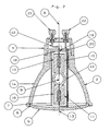
- a reflector lamp 1 shows a first embodiment of a reflector lamp 1, in particular a metal halide reflector lamp, with a outer, designed as a reflector 2 with a neck region 3 Cover with a base 4 and a translucent cover 5, in particular a lens, which along its circumference 6 with a Outer edge 7 of the reflector 2 is connected.
- Reflector 2 base 4 and cover 5 are essentially rotationally symmetrical about a longitudinal axis 8.
- a burner is located in the reflector 2 between the base 4 and the cover 5 9 with end seals 10 and 11 arranged, the is surrounded by a tubular shield 14.
- the Shielding can not only serve as burst protection, but also consist of UV-absorbing glass or with a UV-absorbing Layer to be undesirable To avoid sodium ion loss.
- the burner 9 will by means of a first and a second feed line 12 and 13 in the shield 14 held, the first lead 12 on base-side first burner end 15 and second feed line 13 at the cover-side second burner end 16 in each of the Pinch seals 10,11 is sealed.
- the arrangement of the Burner 9 takes place as concentrically as possible along the rotational or longitudinal axis 8.
- the second feed line 13 is on the outside of the Shield 14 laid and in its cover end 17 introduced.
- the second feed line 13 is under such Bias that shield 14 from this second, against the cover-side end 17 of the shield 14 from the outside 17 'adjacent feed line 13 against a bottom 18 of the Neck area 3 of the reflector 2 is pressed, the Feed lines 12, 13 through openings 19, 20 in this floor 18 through to the bottom in this embodiment Base 4 guided and fixed there or mechanically fixed are.
- the ends of the feed lines 12 and 13 are in the Base 4 attached terminals 21 and 22 electrically connected.
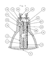
- the second embodiment of the shown in Figure 2 Reflector lamp 1a corresponds essentially to the first Embodiment according to Figure 1, except for the fact that the shield 14 in the same way as on the base side above or is open on the cover side, in other words there is Shield 14 from a cylinder open on both sides. there is the second supply line 13 in the region 17 'at the top of the Shield 14 and presses it against the floor 18.
- Reflector lamp 1b is a first heat shield 23, which base-side end 10 of the burner 9 in the area of it Crimp seal above the weld between supply line 12 and sealing film 12 'and lies opposite the bottom 18, with an opening 24 for the passage of the second Supply line 13 is provided, this opening 24 with the corresponding opening 20 in the floor 18 is aligned.
- this is the first heat shield 23 on the base side by supports 23 'in the neck area 3 and on the cover side through the through the second feed line 13 shield 14 used fixed.
- the second feed line 13 and the first heat shield 23 are in the Area of the opening 24 advantageously against each other isolated.
- the heat shield 23 shields the area of the pinch seal, in which is the weld between the supply line and the sealing foil 12 'is located against the heat radiated by the burner 9 becomes.
- Heat shield may be provided, which is the cover end 16 of the burner 9 in the area of its pinch seal 11 below the weld between the feed line and the sealing foil and the upper end 17 of the shield 14 is opposite on the inside.
- Reflector lamp 1c is both between the base first End 15 of the burner 9 and the shield 14 on the one hand as also between the shield 14 and the reflector neck 3 on the other hand cement 28 introduced in such a way that on the one hand a Cooling effect is achieved, the oxidation of the weld prevented between supply line 12 and sealing film, and on the other hand, the entire structure becomes even more stable.
- Reflector lamp 1d is the point 25 at which the first feed line 12 in the associated pinch seal 10 of the first burner end 15 enters, sealed with glass solder 29.
- glass solder 29 and 29 ' sodium silicate glass can also be used.
- the feed lines 12, 13 can also optionally platinum or coated with quartz glass, what is not shown in detail. Also in not shown In this way, the feed line 13 can each be in the region of the Crimp seals 10 and 11 to be electrically isolated Example with a ceramic sleeve.
Landscapes
- Non-Portable Lighting Devices Or Systems Thereof (AREA)
- Securing Globes, Refractors, Reflectors Or The Like (AREA)
- Common Detailed Techniques For Electron Tubes Or Discharge Tubes (AREA)
Abstract
Description
- Fig. 1
- eine erste Ausführungsform der Erfindung im Querschnitt;
- Fig. 2
- eine zweite Ausführungsform im Querschnitt;
- Fig. 3
- eine dritte Ausführungsform im Querschnitt;
- Fig. 4
- eine vierte Ausführungsform im Querschnitt;
- Fig. 5
- eine fünfte Ausführungsform im Querschnitt;
Claims (12)
- Reflektorlampe (1, 1a, 1b, 1c, 1d), insbesondere Metallhalogendampf-Reflektorlampe, mit einer äußeren, als Reflektor (2) mit einem Halsbereich (3) ausgebildeten Hülle mit einem Sockel (4) und einer lichtdurchlässigen Abdeckung (5), insbesondere einer Linse, die längs ihres Umfangs (6) mit einem Außenrand (7) des Reflektors verbunden ist, wobei Reflektor, Sockel und Abdeckung im wesentlichen rotationssymmetrisch um eine Längsachse (8) ausgebildet sind, und mit einem zwischen Sockel und Abdeckung im Reflektor angeordneten, von einer hüllrohrförmigen Abschirmung (14) umgebenen Brenner (9) mit endseitigen Quetschdichtungen (10,11), der mittels einer ersten und einer zweiten Zuleitung (12,13) in der Abschirmung gehalten ist, wobei die erste Zuleitung (12) am sockelseitigen ersten Brennerende (15) und die zweite Zuleitung (13), auf der Außenseite der Abschirmung verlegt und in deren abdeckungsseitiges Ende (17) eingeführt, am abdeckungsseitigen zweiten Brennerende (16) jeweils in den Quetschdichtungen (10,11) eingesiegelt sind,
dadurch gekennzeichnet, dass,
unter Verzicht auf den Brenner (9) gegen die Umgebung abdichtende Einschmelzungen der Zuleitungen (12,13) in der Abschirmung (14), die Zuleitungen (12,13) nur im Sockel (4) befestigt sind und die zweite Zuleitung (13) derart unter Vorspannung steht, dass die Abschirmung (14) von dieser zweiten, gegen das abdeckungsseitige Ende (17) der Abschirmung (14) von außen anliegenden Zuleitung (13) gegen einen Boden (18) im Halsbereich (3) des Reflektors (2) gedrückt ist, wobei die Zuleitungen (12,13) durch Durchbrechungen (19,20) in diesem Boden (18) hindurch zum Sockel (4) geführt und dort festgelegt sind. - Reflektorlampe (1b nach Anspruch 1, dadurch gekennzeichnet, dass ein erster Hitzeschild (23), der das sockelseitige Ende (10) des Brenners (9) im Bereich seiner Quetschdichtung oberhalb der Schweißung zwischen Zuleitung (12) und Einschmelzfolie (12') umfasst und dem Boden (18) gegenüberliegt, mit einer Durchbrechung (24) für den Durchtritt der zweiten Zuleitung(13) vorgesehen ist, wobei diese Durchbrechung (24) mit der entsprechenden Durchbrechung (20) im Boden (18) fluchtet.
- Reflektorlampe (1b) nach Anspruch 2, dadurch gekennzeichnet, dass der erste Hitzeschild (23) sockelseitig durch Auflagen (23') im Halsbereich (3) und abdeckungsseitig durch die durch die zweite Zuleitung (13) herangezogene Abschirmung (14) fixiert ist.
- Reflektorlampe (1b) nach Anspruch 3, dadurch gekennzeichnet, dass die zweite Zuleitung (13) und der erste Hitzeschild (23) im Bereich der Durchbrechung (24) gegeneinander isoliert sind.
- Reflektorlampe (1b) nach Anspruch 2, dadurch gekennzeichnet, dass am abdeckungsseitigen Ende (16) des Brenners (9) ein zweiter Hitzeschild angeordnet ist, der den Bereich seiner Quetschdichtung (11) unterhalb der Schweißung zwischen zweiter Zuleitung (13) und Einschmelzfolie umfasst und dem oberen Ende (17) der Abschirmung (14) innen gegenüberliegt.
- Reflektorlampe (1c) nach Anspruch 1 dadurch gekennzeichnet, dass sowohl zwischen sockelseitigem Ende (15) des Brenners (9) und der Abschirmung (14) einerseits als auch zwischen der Abschirmung (14) und dem Reflektorhals (3) andererseits Zement (28) derart eingebracht ist, dass die Quetschdichtung (10) mindestens bis zur Schweißung zwischen Zuleitung (12) und Einschmelzfolie (12') von Zement (28) abgedeckt ist.
- Reflektorlampe (1d) nach Anspruch 1 dadurch gekennzeichnet, dass die Stelle (18), an der die erste Zuleitung (12) in die zugehörige Quetschdichtung (10) des ersten Brennerendes (15) eintritt, mit Glaslot (29) verschlossen ist.
- Reflektorlampe (1d nach Anspruch 7, dadurch gekennzeichnet, dass auch die Stelle (27) an der die zweite Zuleitung (13) in die zugehörige Quetschdichtung (11) des zweiten Brennerendes (16) eintritt, mit Glaslot (29) verschlossen ist.
- Reflektorlampe (1d) nach Anspruch 1, dadurch gekennzeichnet, dass die Stelle (18), an der die erste Zuleitung (12) in die zugehörige Quetschdichtung (10) des ersten Brennerendes (15) eintritt, mit Natriumsilikatglas (29) verschlossen ist.
- Reflektorlampe (1d) nach Anspruch 1, dadurch gekennzeichnet, dass auch die Stelle (27), an der die zweite Zuleitung (13) in die zugehörige Quetschdichtung (11) des zweiten Brennerendes (16) eintritt, mit Natriumsilikatglas (29') verschlossen ist.
- Reflektorlampe nach einem der vorherigen Ansprüche,
dadurch gekennzeichnet, dass die Zuleitungen (12,13) platiniert sind. - Reflektorlampe nach einem der Ansprüche 1 bis 8,
dadurch gekennzeichnet, dass die Zuleitungen (12,13) mit Quarzglas überzogen sind.
Applications Claiming Priority (2)
| Application Number | Priority Date | Filing Date | Title |
|---|---|---|---|
| DE10233073A DE10233073B3 (de) | 2002-07-19 | 2002-07-19 | Reflektorlampe |
| DE10233073 | 2002-07-19 |
Publications (3)
| Publication Number | Publication Date |
|---|---|
| EP1383159A2 true EP1383159A2 (de) | 2004-01-21 |
| EP1383159A3 EP1383159A3 (de) | 2005-11-02 |
| EP1383159B1 EP1383159B1 (de) | 2008-02-27 |
Family
ID=29762092
Family Applications (1)
| Application Number | Title | Priority Date | Filing Date |
|---|---|---|---|
| EP03016145A Expired - Lifetime EP1383159B1 (de) | 2002-07-19 | 2003-07-16 | Reflektorlampe |
Country Status (4)
| Country | Link |
|---|---|
| EP (1) | EP1383159B1 (de) |
| AT (1) | ATE387719T1 (de) |
| DE (2) | DE10233073B3 (de) |
| ES (1) | ES2302883T3 (de) |
Cited By (3)
| Publication number | Priority date | Publication date | Assignee | Title |
|---|---|---|---|---|
| EP1659617A1 (de) * | 2004-11-18 | 2006-05-24 | Flowil Lighting International (HOLDING) B.V. | Leuchtmittel |
| EP1783422A1 (de) | 2005-11-04 | 2007-05-09 | Flowil Lighting International (HOLDING) B.V. | Einbauleuchte für ein Leuchtmittel, insbesondere für ein Halogenleuchtmittel |
| EP2009668A1 (de) * | 2007-06-29 | 2008-12-31 | Flowil International Lighting (HOLDING) B.V. | Einseitig gesockelte Entladungslampe |
Families Citing this family (4)
| Publication number | Priority date | Publication date | Assignee | Title |
|---|---|---|---|---|
| US7172317B2 (en) | 2003-10-01 | 2007-02-06 | Sli Lichtsysteme Gmbh | Reflector lamp |
| DE102004004651B3 (de) | 2004-01-29 | 2005-12-01 | Flowil International Lighting (Holding) B.V. | Lampe für allgemeine Beleuchtungszwecke |
| DE502007001845D1 (de) | 2007-03-16 | 2009-12-10 | Flowil Int Lighting | Reflektorlampe mit Hüllkolben |
| TW201116753A (en) | 2009-09-30 | 2011-05-16 | Ceram Tec Gmbh | Lamp having a variable substrate as a base for a light source |
Citations (2)
| Publication number | Priority date | Publication date | Assignee | Title |
|---|---|---|---|---|
| EP0902458A2 (de) * | 1997-09-11 | 1999-03-17 | Osram Sylvania Inc. | Niederleistungslampe mit geformter Bogenröhre in Aluminiumsilikat Aussenmantel |
| WO2002031851A1 (en) * | 2000-10-06 | 2002-04-18 | General Electric Company | Lamp mount with a lamp mounting tube |
Family Cites Families (9)
| Publication number | Priority date | Publication date | Assignee | Title |
|---|---|---|---|---|
| GB1333158A (en) * | 1971-09-15 | 1973-10-10 | Thorn Electrica Ind Ltd | Double-ended halogen lamp with metal reflector |
| US4935668A (en) * | 1988-02-18 | 1990-06-19 | General Electric Company | Metal halide lamp having vacuum shroud for improved performance |
| US4939408A (en) * | 1988-06-29 | 1990-07-03 | North American Philips Corp. | High pressure sodium discharge reflector lamp |
| US4961019A (en) * | 1988-10-14 | 1990-10-02 | Gte Products Corporation | Metal halide lamp assembly |
| US5043623A (en) * | 1990-12-06 | 1991-08-27 | Gte Products Corporation | Reflector lamp assembly including metal halide arc tube |
| WO1996027205A1 (en) * | 1995-03-02 | 1996-09-06 | Philips Electronics N.V. | Electric reflector lamp |
| US6002197A (en) * | 1996-04-24 | 1999-12-14 | Ushiodenki Kabushiki Kaisha | Metal halide lamp light source device having conducting wire positioned to prevent it from casting a shadow |
| US5998915A (en) * | 1997-05-09 | 1999-12-07 | Osram Sylvania Inc. | Mounting support for a high intensity discharge reflector lamp |
| WO2000075957A1 (en) * | 1999-06-03 | 2000-12-14 | Koninklijke Philips Electronics N.V. | Electric lamp/reflector unit |
-
2002
- 2002-07-19 DE DE10233073A patent/DE10233073B3/de not_active Expired - Fee Related
-
2003
- 2003-07-16 AT AT03016145T patent/ATE387719T1/de not_active IP Right Cessation
- 2003-07-16 DE DE50309244T patent/DE50309244D1/de not_active Expired - Lifetime
- 2003-07-16 EP EP03016145A patent/EP1383159B1/de not_active Expired - Lifetime
- 2003-07-16 ES ES03016145T patent/ES2302883T3/es not_active Expired - Lifetime
Patent Citations (2)
| Publication number | Priority date | Publication date | Assignee | Title |
|---|---|---|---|---|
| EP0902458A2 (de) * | 1997-09-11 | 1999-03-17 | Osram Sylvania Inc. | Niederleistungslampe mit geformter Bogenröhre in Aluminiumsilikat Aussenmantel |
| WO2002031851A1 (en) * | 2000-10-06 | 2002-04-18 | General Electric Company | Lamp mount with a lamp mounting tube |
Cited By (3)
| Publication number | Priority date | Publication date | Assignee | Title |
|---|---|---|---|---|
| EP1659617A1 (de) * | 2004-11-18 | 2006-05-24 | Flowil Lighting International (HOLDING) B.V. | Leuchtmittel |
| EP1783422A1 (de) | 2005-11-04 | 2007-05-09 | Flowil Lighting International (HOLDING) B.V. | Einbauleuchte für ein Leuchtmittel, insbesondere für ein Halogenleuchtmittel |
| EP2009668A1 (de) * | 2007-06-29 | 2008-12-31 | Flowil International Lighting (HOLDING) B.V. | Einseitig gesockelte Entladungslampe |
Also Published As
| Publication number | Publication date |
|---|---|
| ATE387719T1 (de) | 2008-03-15 |
| DE50309244D1 (de) | 2008-04-10 |
| DE10233073B3 (de) | 2004-02-12 |
| ES2302883T3 (es) | 2008-08-01 |
| EP1383159B1 (de) | 2008-02-27 |
| EP1383159A3 (de) | 2005-11-02 |
Similar Documents
| Publication | Publication Date | Title |
|---|---|---|
| EP0479087B1 (de) | Hochdruckentladungslampe | |
| DE69629336T2 (de) | Hochdruckentladungslampe und ihr herstellungsverfahren | |
| DE4435261A1 (de) | Quarzlampe | |
| DE3616329A1 (de) | Kurzbogenlampe | |
| EP1111655B1 (de) | Einschmelzfolie und zugehörige Lampe mit dieser Folie | |
| EP0264764A2 (de) | Einschmelzung für eine Hochdruckentladungslampe | |
| DE2623099A1 (de) | Kurzbogenentladungslampe | |
| DE2641867A1 (de) | Elektrische entladungslampe | |
| EP0602529A2 (de) | Hochdruckentladungslampe mit einem keramischen Entladungsgefäss | |
| DE3616330A1 (de) | Kurzbogenlampe | |
| EP1383159B1 (de) | Reflektorlampe | |
| DE60038407T2 (de) | Kurzbogen-Entladungslampe | |
| DE69923663T2 (de) | Elektrische lampe | |
| DE69928503T2 (de) | Lampe mit schutzhülle | |
| DE2737931C2 (de) | Endverschluß für eine Entladungslampe | |
| DE69927574T2 (de) | Elektrische lampe mit einem beschichteten aussenstromleiter | |
| DE10242035A1 (de) | Einschmelzfolie und zugehörige Lampe mit dieser Folie | |
| DE3043193A1 (de) | Elektrische lampe | |
| DE3009733C2 (de) | Blitzentladungslampe | |
| DE3743627A1 (de) | Hochdruckentladungslampe | |
| EP1745501B1 (de) | Glühwendel für eine glühlampe und glühlampe | |
| DE2915556A1 (de) | Elektrische lampe | |
| DE19963838B4 (de) | Getter-Spritzabschirmung | |
| DE2909771A1 (de) | Elektrische lampe | |
| DE102006047389B4 (de) | Lampe mit Metallfolienabdichtung, die einen geschlitzten Metallstift und eine damit verbundene Metallfolie umfasst |
Legal Events
| Date | Code | Title | Description |
|---|---|---|---|
| PUAI | Public reference made under article 153(3) epc to a published international application that has entered the european phase |
Free format text: ORIGINAL CODE: 0009012 |
|
| AK | Designated contracting states |
Kind code of ref document: A2 Designated state(s): AT BE BG CH CY CZ DE DK EE ES FI FR GB GR HU IE IT LI LU MC NL PT RO SE SI SK TR |
|
| AX | Request for extension of the european patent |
Extension state: AL LT LV MK |
|
| RIN1 | Information on inventor provided before grant (corrected) |
Inventor name: DERHAEGH, LODE Inventor name: VAN DEN BROECK, MARC Inventor name: GEENS, RUDY |
|
| PUAL | Search report despatched |
Free format text: ORIGINAL CODE: 0009013 |
|
| AK | Designated contracting states |
Kind code of ref document: A3 Designated state(s): AT BE BG CH CY CZ DE DK EE ES FI FR GB GR HU IE IT LI LU MC NL PT RO SE SI SK TR |
|
| AX | Request for extension of the european patent |
Extension state: AL LT LV MK |
|
| 17P | Request for examination filed |
Effective date: 20060427 |
|
| AKX | Designation fees paid |
Designated state(s): AT BE BG CH CY CZ DE DK EE ES FI FR GB GR HU IE IT LI LU MC NL PT RO SE SI SK TR |
|
| GRAP | Despatch of communication of intention to grant a patent |
Free format text: ORIGINAL CODE: EPIDOSNIGR1 |
|
| GRAS | Grant fee paid |
Free format text: ORIGINAL CODE: EPIDOSNIGR3 |
|
| GRAA | (expected) grant |
Free format text: ORIGINAL CODE: 0009210 |
|
| AK | Designated contracting states |
Kind code of ref document: B1 Designated state(s): AT BE BG CH CY CZ DE DK EE ES FI FR GB GR HU IE IT LI LU MC NL PT RO SE SI SK TR |
|
| REG | Reference to a national code |
Ref country code: GB Ref legal event code: FG4D Free format text: NOT ENGLISH |
|
| RIN1 | Information on inventor provided before grant (corrected) |
Inventor name: VAN DEN BROECK, MARC Inventor name: GEENS, RUDY Inventor name: DERHAEGH, LODE |
|
| REG | Reference to a national code |
Ref country code: CH Ref legal event code: EP |
|
| REG | Reference to a national code |
Ref country code: IE Ref legal event code: FG4D Free format text: LANGUAGE OF EP DOCUMENT: GERMAN |
|
| REF | Corresponds to: |
Ref document number: 50309244 Country of ref document: DE Date of ref document: 20080410 Kind code of ref document: P |
|
| PG25 | Lapsed in a contracting state [announced via postgrant information from national office to epo] |
Ref country code: FI Free format text: LAPSE BECAUSE OF FAILURE TO SUBMIT A TRANSLATION OF THE DESCRIPTION OR TO PAY THE FEE WITHIN THE PRESCRIBED TIME-LIMIT Effective date: 20080227 |
|
| REG | Reference to a national code |
Ref country code: ES Ref legal event code: FG2A Ref document number: 2302883 Country of ref document: ES Kind code of ref document: T3 |
|
| PG25 | Lapsed in a contracting state [announced via postgrant information from national office to epo] |
Ref country code: SI Free format text: LAPSE BECAUSE OF FAILURE TO SUBMIT A TRANSLATION OF THE DESCRIPTION OR TO PAY THE FEE WITHIN THE PRESCRIBED TIME-LIMIT Effective date: 20080227 |
|
| REG | Reference to a national code |
Ref country code: IE Ref legal event code: FD4D |
|
| PG25 | Lapsed in a contracting state [announced via postgrant information from national office to epo] |
Ref country code: SK Free format text: LAPSE BECAUSE OF FAILURE TO SUBMIT A TRANSLATION OF THE DESCRIPTION OR TO PAY THE FEE WITHIN THE PRESCRIBED TIME-LIMIT Effective date: 20080227 Ref country code: SE Free format text: LAPSE BECAUSE OF FAILURE TO SUBMIT A TRANSLATION OF THE DESCRIPTION OR TO PAY THE FEE WITHIN THE PRESCRIBED TIME-LIMIT Effective date: 20080527 Ref country code: PT Free format text: LAPSE BECAUSE OF FAILURE TO SUBMIT A TRANSLATION OF THE DESCRIPTION OR TO PAY THE FEE WITHIN THE PRESCRIBED TIME-LIMIT Effective date: 20080721 Ref country code: IE Free format text: LAPSE BECAUSE OF FAILURE TO SUBMIT A TRANSLATION OF THE DESCRIPTION OR TO PAY THE FEE WITHIN THE PRESCRIBED TIME-LIMIT Effective date: 20080227 Ref country code: DK Free format text: LAPSE BECAUSE OF FAILURE TO SUBMIT A TRANSLATION OF THE DESCRIPTION OR TO PAY THE FEE WITHIN THE PRESCRIBED TIME-LIMIT Effective date: 20080227 Ref country code: CZ Free format text: LAPSE BECAUSE OF FAILURE TO SUBMIT A TRANSLATION OF THE DESCRIPTION OR TO PAY THE FEE WITHIN THE PRESCRIBED TIME-LIMIT Effective date: 20080227 |
|
| ET | Fr: translation filed | ||
| PG25 | Lapsed in a contracting state [announced via postgrant information from national office to epo] |
Ref country code: RO Free format text: LAPSE BECAUSE OF FAILURE TO SUBMIT A TRANSLATION OF THE DESCRIPTION OR TO PAY THE FEE WITHIN THE PRESCRIBED TIME-LIMIT Effective date: 20080227 |
|
| PLBE | No opposition filed within time limit |
Free format text: ORIGINAL CODE: 0009261 |
|
| STAA | Information on the status of an ep patent application or granted ep patent |
Free format text: STATUS: NO OPPOSITION FILED WITHIN TIME LIMIT |
|
| 26N | No opposition filed |
Effective date: 20081128 |
|
| REG | Reference to a national code |
Ref country code: CH Ref legal event code: PL |
|
| PG25 | Lapsed in a contracting state [announced via postgrant information from national office to epo] |
Ref country code: MC Free format text: LAPSE BECAUSE OF NON-PAYMENT OF DUE FEES Effective date: 20080731 |
|
| PG25 | Lapsed in a contracting state [announced via postgrant information from national office to epo] |
Ref country code: EE Free format text: LAPSE BECAUSE OF FAILURE TO SUBMIT A TRANSLATION OF THE DESCRIPTION OR TO PAY THE FEE WITHIN THE PRESCRIBED TIME-LIMIT Effective date: 20080227 Ref country code: BG Free format text: LAPSE BECAUSE OF FAILURE TO SUBMIT A TRANSLATION OF THE DESCRIPTION OR TO PAY THE FEE WITHIN THE PRESCRIBED TIME-LIMIT Effective date: 20080527 |
|
| PG25 | Lapsed in a contracting state [announced via postgrant information from national office to epo] |
Ref country code: CH Free format text: LAPSE BECAUSE OF NON-PAYMENT OF DUE FEES Effective date: 20080731 Ref country code: LI Free format text: LAPSE BECAUSE OF NON-PAYMENT OF DUE FEES Effective date: 20080731 |
|
| PG25 | Lapsed in a contracting state [announced via postgrant information from national office to epo] |
Ref country code: CY Free format text: LAPSE BECAUSE OF FAILURE TO SUBMIT A TRANSLATION OF THE DESCRIPTION OR TO PAY THE FEE WITHIN THE PRESCRIBED TIME-LIMIT Effective date: 20080227 |
|
| PG25 | Lapsed in a contracting state [announced via postgrant information from national office to epo] |
Ref country code: AT Free format text: LAPSE BECAUSE OF NON-PAYMENT OF DUE FEES Effective date: 20080716 |
|
| PG25 | Lapsed in a contracting state [announced via postgrant information from national office to epo] |
Ref country code: HU Free format text: LAPSE BECAUSE OF FAILURE TO SUBMIT A TRANSLATION OF THE DESCRIPTION OR TO PAY THE FEE WITHIN THE PRESCRIBED TIME-LIMIT Effective date: 20080828 Ref country code: LU Free format text: LAPSE BECAUSE OF NON-PAYMENT OF DUE FEES Effective date: 20080716 |
|
| PG25 | Lapsed in a contracting state [announced via postgrant information from national office to epo] |
Ref country code: TR Free format text: LAPSE BECAUSE OF FAILURE TO SUBMIT A TRANSLATION OF THE DESCRIPTION OR TO PAY THE FEE WITHIN THE PRESCRIBED TIME-LIMIT Effective date: 20080227 |
|
| PG25 | Lapsed in a contracting state [announced via postgrant information from national office to epo] |
Ref country code: GR Free format text: LAPSE BECAUSE OF FAILURE TO SUBMIT A TRANSLATION OF THE DESCRIPTION OR TO PAY THE FEE WITHIN THE PRESCRIBED TIME-LIMIT Effective date: 20080528 |
|
| REG | Reference to a national code |
Ref country code: DE Ref legal event code: R082 Ref document number: 50309244 Country of ref document: DE Representative=s name: GOEHMANN RECHTSANWAELTE, DE |
|
| REG | Reference to a national code |
Ref country code: DE Ref legal event code: R082 Ref document number: 50309244 Country of ref document: DE Representative=s name: GOEHMANN RECHTSANWAELTE, DE |
|
| REG | Reference to a national code |
Ref country code: DE Ref legal event code: R081 Ref document number: 50309244 Country of ref document: DE Owner name: HAVEILS SYLVANIA GERMANY GMBH, DE Free format text: FORMER OWNER: SLI LICHTSYSTEME GMBH, 91056 ERLANGEN, DE Effective date: 20141107 Ref country code: DE Ref legal event code: R082 Ref document number: 50309244 Country of ref document: DE Representative=s name: GOEHMANN RECHTSANWAELTE, DE Effective date: 20141107 Ref country code: DE Ref legal event code: R082 Ref document number: 50309244 Country of ref document: DE Representative=s name: GOEHMANN RECHTSANWAELTE, DE Effective date: 20131218 |
|
| REG | Reference to a national code |
Ref country code: NL Ref legal event code: TD Effective date: 20150129 |
|
| REG | Reference to a national code |
Ref country code: FR Ref legal event code: PLFP Year of fee payment: 14 |
|
| PGFP | Annual fee paid to national office [announced via postgrant information from national office to epo] |
Ref country code: NL Payment date: 20160728 Year of fee payment: 14 |
|
| PGFP | Annual fee paid to national office [announced via postgrant information from national office to epo] |
Ref country code: GB Payment date: 20160728 Year of fee payment: 14 Ref country code: IT Payment date: 20160728 Year of fee payment: 14 Ref country code: DE Payment date: 20160726 Year of fee payment: 14 |
|
| PGFP | Annual fee paid to national office [announced via postgrant information from national office to epo] |
Ref country code: FR Payment date: 20160719 Year of fee payment: 14 |
|
| PGFP | Annual fee paid to national office [announced via postgrant information from national office to epo] |
Ref country code: ES Payment date: 20160729 Year of fee payment: 14 Ref country code: BE Payment date: 20160728 Year of fee payment: 14 |
|
| REG | Reference to a national code |
Ref country code: DE Ref legal event code: R119 Ref document number: 50309244 Country of ref document: DE |
|
| REG | Reference to a national code |
Ref country code: NL Ref legal event code: MM Effective date: 20170801 |
|
| GBPC | Gb: european patent ceased through non-payment of renewal fee |
Effective date: 20170716 |
|
| REG | Reference to a national code |
Ref country code: FR Ref legal event code: ST Effective date: 20180330 |
|
| PG25 | Lapsed in a contracting state [announced via postgrant information from national office to epo] |
Ref country code: NL Free format text: LAPSE BECAUSE OF NON-PAYMENT OF DUE FEES Effective date: 20170801 Ref country code: DE Free format text: LAPSE BECAUSE OF NON-PAYMENT OF DUE FEES Effective date: 20180201 Ref country code: GB Free format text: LAPSE BECAUSE OF NON-PAYMENT OF DUE FEES Effective date: 20170716 |
|
| PG25 | Lapsed in a contracting state [announced via postgrant information from national office to epo] |
Ref country code: FR Free format text: LAPSE BECAUSE OF NON-PAYMENT OF DUE FEES Effective date: 20170731 |
|
| REG | Reference to a national code |
Ref country code: BE Ref legal event code: HC Owner name: HAVELLS SYLVANIA GERMANY GMBH; DE Free format text: DETAILS ASSIGNMENT: CHANGE OF OWNER(S), CHANGEMENT NOM PROPRIETAIRE; FORMER OWNER NAME: SLI LICHTSYSTEME GMBH Effective date: 20150810 Ref country code: BE Ref legal event code: MM Effective date: 20170731 |
|
| PG25 | Lapsed in a contracting state [announced via postgrant information from national office to epo] |
Ref country code: BE Free format text: LAPSE BECAUSE OF NON-PAYMENT OF DUE FEES Effective date: 20170731 Ref country code: IT Free format text: LAPSE BECAUSE OF NON-PAYMENT OF DUE FEES Effective date: 20170716 |
|
| REG | Reference to a national code |
Ref country code: ES Ref legal event code: FD2A Effective date: 20181105 |
|
| PG25 | Lapsed in a contracting state [announced via postgrant information from national office to epo] |
Ref country code: ES Free format text: LAPSE BECAUSE OF NON-PAYMENT OF DUE FEES Effective date: 20170717 |