EP1382557A1 - Spule, Spulenflansch und Zuganker - Google Patents
Spule, Spulenflansch und Zuganker Download PDFInfo
- Publication number
- EP1382557A1 EP1382557A1 EP03016010A EP03016010A EP1382557A1 EP 1382557 A1 EP1382557 A1 EP 1382557A1 EP 03016010 A EP03016010 A EP 03016010A EP 03016010 A EP03016010 A EP 03016010A EP 1382557 A1 EP1382557 A1 EP 1382557A1
- Authority
- EP
- European Patent Office
- Prior art keywords
- coil
- tie rod
- flange
- tie
- tie rods
- Prior art date
- Legal status (The legal status is an assumption and is not a legal conclusion. Google has not performed a legal analysis and makes no representation as to the accuracy of the status listed.)
- Granted
Links
Images



Classifications
-
- B—PERFORMING OPERATIONS; TRANSPORTING
- B65—CONVEYING; PACKING; STORING; HANDLING THIN OR FILAMENTARY MATERIAL
- B65H—HANDLING THIN OR FILAMENTARY MATERIAL, e.g. SHEETS, WEBS, CABLES
- B65H75/00—Storing webs, tapes, or filamentary material, e.g. on reels
- B65H75/02—Cores, formers, supports, or holders for coiled, wound, or folded material, e.g. reels, spindles, bobbins, cop tubes, cans, mandrels or chucks
- B65H75/18—Constructional details
- B65H75/22—Constructional details collapsible; with removable parts
- B65H75/2218—Collapsible hubs
- B65H75/2227—Collapsible hubs with a flange fixed to the hub part
-
- B—PERFORMING OPERATIONS; TRANSPORTING
- B65—CONVEYING; PACKING; STORING; HANDLING THIN OR FILAMENTARY MATERIAL
- B65H—HANDLING THIN OR FILAMENTARY MATERIAL, e.g. SHEETS, WEBS, CABLES
- B65H2701/00—Handled material; Storage means
- B65H2701/50—Storage means for webs, tapes, or filamentary material
- B65H2701/51—Cores or reels characterised by the material
- B65H2701/513—Cores or reels characterised by the material assembled mainly from rigid elements of the same kind
- B65H2701/5132—Wooden planks or similar material
-
- B—PERFORMING OPERATIONS; TRANSPORTING
- B65—CONVEYING; PACKING; STORING; HANDLING THIN OR FILAMENTARY MATERIAL
- B65H—HANDLING THIN OR FILAMENTARY MATERIAL, e.g. SHEETS, WEBS, CABLES
- B65H2701/00—Handled material; Storage means
- B65H2701/50—Storage means for webs, tapes, or filamentary material
- B65H2701/51—Cores or reels characterised by the material
- B65H2701/513—Cores or reels characterised by the material assembled mainly from rigid elements of the same kind
- B65H2701/5136—Moulded plastic elements
Definitions
- Such coils are preferably used to transport Cables, strands, piping and similar products. It deals are medium-sized coils with a flange diameter of e.g. 5 ⁇ mm.
- a coil of the type mentioned is known from EP 1176111 A2. It is a wooden spool. The two flanges have aligned through holes for the tie rods, the holes corresponding to the cross section of the tie rods. One end of the rod-shaped tie rod shown there is angled and the angled end serves as a stop when pushing through and as an abutment when connecting the flanges to the core. The second end of the tie rod, which projects minimally on the outside on the opposite flange side, is secured by a clamping nut and is designed without any final deformation. The clamping nut is placed on the undeformed ends of the tie rods in a press-like device in which the assembled coil is received and ensures the tensioning of the entire coil.
- the invention is therefore based on the object of a coil propose that is simpler in its structure and without one Pick-up device for the coil does not require assembly and is particularly inexpensive.
- An embodiment of the invention is characterized in that both ends of the tie rods projecting radially in the flange plane are formed by bending the rod ends. This eliminates the need for additional components to clamp the flanges. Bending the ends of the rod-shaped tie rods is an inexpensive manufacturing process.
- the tie rods can be completely prefabricated industrially. This measure also has the advantage that both flanges can be of the same design. By spreading the bent ends of the tie rods, which make them look like clips, and loosening the fixation, the coil can be easily removed without destroying the tie rods.
- the means are proposed to fix the at least one with the radially projecting Section formed end with a further bend to provide the free rod end, this second Bending a recess or a projection on the outside in the flange assigned.
- the distance between the first and the second, sharp-edged kink on the one under consideration End section of the tie rod is dimensioned so elastic that the second bend during assembly and disassembly after can be pulled outside and in the final position of the complete tie rod with the recess or the projection hooked.
- a recess for snagging the entire reshaping of the ends takes the form of a handle Walking stick.
- the recesses in the flange for the stub-shaped pegs are preferably considered to be about that Bores corresponding to the diameter of the stub-shaped pins educated. They can be used as blind or through holes be designed.
- Retained tie rod with two double angled ends with its straight middle section an approximately C-shaped shape.
- the C-shape lies in one plane.
- the angled from the middle sections of the tie rods can also be in Circumferential direction or also inwards on the coil axis point if due to the size of the coil for such Arrangement is enough space.
- Another embodiment of the invention is characterized by at least one plug with which after the tie rod is installed remaining hole sections in the flanges closed and the tie rods are fixed in the remaining hole.
- This embodiment is particularly suitable for Plastic coils in which the plugs, e.g. with a Film hinge can be molded immediately.
- Invention can be provided that both ends of the rod-like Tie rods are kinked twice and the outermost Dip the bent sections into the flange wall.
- tie rod a have flat long sides. Practically band irons come here or square wire as a raw material for the tie rods in Question.
- At least one tie rod in a resting seat between the core and Push-through opening is fixed in the flange or between the core and Push-through opening is jammed.
- the tie rods are preferably made of steel and the coil material is otherwise comparatively soft, it can be assumed that the load of the winding changes with the considered tie rod end supported twice on the flange, namely with the stub-shaped end sections of the double angled tie rod that is in the flange from the outside reach in and with the end portions of the core penetrating middle sections of the tie rod.
- the perforations for the tie rods tolerable since it is preferably disposable coils.
- a plywood coil 2 which consists of two Flanges 2, 3 and a core 4, the flanges 2,3 and the core 4 by preferably at least three tie rods 5 be held together.
- Tie rods 6 evenly distributed, only one of which is shown is.
- the tie rods 5 are through holes 9, 1 ⁇ in the flanges 2, 3 inserted.
- the tie rods 5 start from their Middle section 6 within the core 4 at both ends end sections 7, 8 angled to a clamp, at the Pins 11, 12 pointing into the winding space 25 of the coil 1 are formed by a further bend.
- the pins 11, 12 serve to fix the tie rod in the coil.
- Both Bends of each anchor end lie in the same plane, a longitudinal plane of the coil 1.
- the pins 11, 12 engage in Recesses 14, 15 in the flanges 2, 3 at the level of Changing room 25 are arranged.
- the tie rods 5 are off Square wire made.
- the tie rods 5 are used for assembly the coil 1 through the holes 9, 1 ⁇ in the flanges 2, 3 plugged.
- the holes 9, 1 ⁇ are dimensioned so that the bent ends 7, 8 fit through holes 9, 1 ⁇ .
- the circumference 23 touches the holes 9, 1 ⁇ the inner circumference 24 of the core 4.
- the free ends of the bent end sections 3 ⁇ are with molded and through a further bending process stub-shaped formed in the circumferential direction of the coil Provide pin 31.
- Both the end sections 3 ⁇ and stub-shaped pins 31 are at least partially in shape, of the end portions and their stub-like pins 31 adapted recesses 32 embedded in the flange 26.
- the recess 32 is the complete tie rod 29 its end portions 3 ⁇ and its stub-shaped pin 31st fixed without degree of freedom, related to the coil.
- tie rod 39 in particular for a wooden spool shown that at the transition of the central train section to the section in the flange plane with sharp edges bent end portions 37 carries the inside Complete bent pin 4 ⁇ .
- the tie rod 39 corresponds to the tie rod 6 from FIG. 1.
- the A special feature of the tie rod 39 is a rectangular cross section 38.
- the end portions 37 and the pin 4 ⁇ are on the Broad sides of the rectangular cross section curved.
- the tie rod 42 in the embodiment of the tie rod 42 according to FIG. 8 for a Wooden spool is the starting material of a round wire, like from the sectional view at 45 can be seen.
- the tie rod 42 corresponds to the tie rod 5 in Fig.1. Only the one is shown left section of the tie rod in Fig. 1.
- the round wire with the at 45 shown profile extends almost to the entire length of the coil (not shown) inside.
- the round material is flattened, as from the Cross-sectional view at 44 and lies with his Flat side 47 on and in the flange to the surface pressure between tie rod and flange and reduce the forces required to bend the bent ends of the To lower tie rods.
- the end sections 7, 8, 37 and 43 are of their length and Cross-sectional dimensioning designed so that it around protruding dimension of the stub-shaped pin 11, 12, 4 ⁇ , 46 of Hand - if necessary be bent up elastically with a tool can and to complete the assembly of the tie rods and after Loosen the bend elastically in a recess 14, 15 Spring back (Fig.1) in the coil flange.
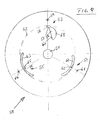
- a circular flange 5 ⁇ is shown, which in has a central bore 51 in its center.
- she is Arrangement of the core - not shown here - dashed indicated, since the arrangement of the holes only in relation to the Location of the core can be seen.
- the flange 5 ⁇ are three pairs 53, 54, 55 of holes shown, the holes of a pair essentially enclose the core face between them.
- Each pair of holes 53, 54, 55 is used for receiving and anchoring one end of a tie rod on the flange.
- Tie rods are provided per spool.
- the opening 58 is in the form of a walking stick, which projects with its “handle” into the arrangement area 52 of the core and, with an inspection and guide extension 68, facilitates the passage of the end of the tie rod through the opening 58.
- the tie rod can be guided with a pair of pointed pliers or a hook and pulled through the opening and inserted with its stub into the hook hole 59.
- the grip area of the walking stick has a latching seat 56 and a latching nose 57, on which an end region of the central section of a tie rod is supported temporarily — latching nose 57 — and finally — latching seat 56.
- the tie rod made of round wire nestles into the rest seat 56 with its circumference.
- the pair of holes 54 consists of a circular segment Opening 6 ⁇ , which has a clamping point 62 with its longitudinal center forms and there the intended arrangement 52 of the core cuts and with their ends in the projection of the Core interior lies.
- the opening is 6 ⁇ mirror image of a radius through the hook hole 61 educated.
- the tie rod In the assembled position, the tie rod is with its middle section at the nip 62 through the reveal the opening 6 ⁇ and slightly at this point bulged core clamped. This creates a centering of the core with its prestress.
- the pair of holes 55 consists of a hook hole 64 and one Opening 63, which is also a mirror image of a radius is formed by the hook hole 64, such as the opening 6 ⁇ of hole pair 54. It has on the radius through the hook hole 64 a rest seat, which is delimited on both sides by locking lugs 66.
- the opening 63 also cuts the core arrangement 52, so that the tie rod, when installed, shears in its Rest seat 65 between this and the core inner wall is clamped.
Landscapes
- Storage Of Web-Like Or Filamentary Materials (AREA)
Abstract
Description
Es wird dort auch erwähnt, daß das zweite Stangenende nachträglich vernietet, aufgeweitet oder verformt werden kann, wobei diese Verformung einen zusätzlichen Ring, eine Unterlegscheibe oder aehnliches sichern soll.
Durch Spreizen der umgebogenen, den Klammercharakter ausmachenden Enden der Zuganker und das dabei erfolgende Lösen der Fixierung wird die Spule einfach demontierbar ohne Zerstörung der Zuganker.
- Fig. 1 :
- Eine Spule im Halbschnitt nach der Erfindung;
- Fig. 2 :
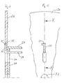
- einen Ausschnitt aus einer Seitenansicht von Fig. 1;
- Fig. 3 :
- einen Ausschnitt aus einer Seitenansicht eines Spulenflansches;
- Fig. 4 :
- einen Schnitt nach Linie IV-IV in Fig.3;
- Fig. 5 :
- einen Ausschnitt aus einem Spulenflansch mit einer besonderen Ausbildung eines Endes eines Zugankers;
- Fig. 6 :
- einen Schnitt nach Linie VI-VI in Fig.5;
- Fig. 7 :
- einen abschnittweise dargestellten Zuganker mit rechteckförmigem Querschnitt;
- Fig. 8 :
- ein Stück Zuganker mit Endabschnitt und spezieller Querschnittsausbildung;
- Fig. 9 :
- Einen Flansch mit unterschiedlichen Ausgestaltungen der Löcher zur Aufnahme der Zuganker.
Der Griffbereich des Spazierstocks hat einen Rastsitz 56 und eine Rastnase 57, an denen sich vorübergehend -- Rastnase 57 -und endgültig -- Rastsitz 56 -- ein Endbereich des Mittelabschnitts eines Zugankers abstützt. Der aus Runddraht gefertigte Zuganker schmiegt sich mit seinem Umfang in den Rastsitz 56 ein. Das Hakloch 59 und der Rastsitz 56 liegen in radialer Fluchtung im Flansch hintereinander. Der gerade Abschnitt 67 der Durchbrechung 58 erstreckt sich fast in radialer Richtung. Die Durchbrechung 58 erlaubt es, das komplette Ende des Zugankers durch den Flansch durchzuziehen. Das Hakloch 59 ist als Durchgangsbohrung ausgebildet. So können auf beiden Seiten des Kerns gleiche Flansche zum Einsatz kommen.
Claims (10)
- Spule (1, 2⊘) mit zwei Flanschen (2, 3, 19, 26) und einem Kern (4, 27, 35)
und mit Zugankern (5, 21, 29, 39, 42) zum Fixieren der Flansche (2, 3, 19, 26) und des Kerns (4, 27, 35) in der fuer die Spulengestalt massgeblichen Anordnung,
wobei die Zuganker (5, 21, 29, 39, 42) durch Löcher (9, 1⊘, 34, 48) in den Flanschen (2, 3, 19, 26) gesteckt werden,
mit mindestens einem umgeformten Ende (7, 8, 25, 3⊘, 37, 43) an dem Zuganker (5, 21, 29, 39, 42), das von dem Mittelabschnitt (6, 41) des Zugankers radial abkragt,
dadurch gekennzeichnet, dass
zwei umgeformte Enden (7, 8, 37) der unmontierten Zuganker (5, 21, 29, 39, 42) vorgesehen sind und
die Loecher (9, 1⊘, 34) in mindestens einem Flansch (2, 3, 19, 26) so gross sind, dass die zugeordneten, umgeformten Enden (7, 8, 25, 3⊘, 37, 43) in Längsrichtung der Zuganker (5, 21, 29, 39, 42) durchgesteckt werden koennen,
und durch Mittel (11, 12, 16, 17, 18, 31, 4⊘, 46, 59, 61, 64) zum Fixieren mindestens eines mit einem radial abkragenden Abschnitt (7, 8, 25, 3⊘, 37, 43) ausgeformten Endes der Zuganker (5, 21, 29, 39, 42) in der Flanschebene in der fertig montierten Anordnung. - Spule (1) nach Anspruch 1, dadurch gekennzeichnet, dass beide in der Flanschebene radial abkragenden Endabschnitte (7, 8, 25, 30, 37, 43) der Zuganker (5, 21, 29, 39, 42) durch Umbiegen gebildet werden.
- Spule (1, 2⊘) nach Anspruch 1 oder 2, dadurch gekennzeichnet, dass die Mittel (11, 12, 16, 17, 18, 31, 4⊘, 46) zum Fixieren des mindestens einen, mit dem radial abkragenden Abschnitt ausgeformten Endes von einer weiteren stummelförmigen Abbiegung des freien Endes des Zugankers (5, 21, 29, 39, 42) gebildet werden, denen eine Ausnehmung (14, 15, 32, 59, 61, 64) im oder ein Vorsprung (16, 17) aussen am Flansch (2, 3, 19, 26) zugeordnet ist.
- Spule (20) nach einem der vorangegangenen Ansprüche, gekennzeichnet durch mindestens einen Stopfen (18) als Teil der Fixiermittel, mit dem, nach Montage der Zuganker (21) verbleibende Lochabschnitte in den Flanschen (19), die Zuganker (21) in dem Loch (48) fixiert werden.
- Spule (1) nach Anspruch 3, dadurch gekennzeichnet, daß die zweite Abbiegung des Zugankers (11, 12, 4⊘, 46) in den Wickelraum (25) der Spule (1) weist und in ein Loch (14, 15, 59, 61, 64) in einer Flanschwand (2, 3, 5⊘) eintaucht.
- Spule (1) nach Anspruch 3 oder Anspruch 5, dadurch gekennzeichnet, daß beide Enden (7, 8, 37) der Zuganker (5, 39) zweifach abgeknickt sind und die äußersten abgeknickten Abschnitte (11, 12, 4⊘) in die Flanschwand (2, 3) eintauchen.
- Spule nach einem der vorangegangenen Ansprüche, dadurch gekennzeichnet, daß die Zuganker (39, 42) eine flache Längsseite (47, 49) aufweisen.
- Spule nach einem der vorangeganenen Ansprueche, dadurch gekennzeichnet, dass mindestens ein Zuganker in einem Rastsitz (56, 65) zwischen Kern und Durchsteckoeffnung (58, 63) im Flansch (5⊘) fixiert ist oder zwischen Kern (52) und Durchsteckoeffnung (58, 63) eingeklemmt ist.
- Zuganker (39) fuer eine Spule nach einem der vorangegangenen Ansprueche, dadurch gekennzeichnet, dass beide Enden (37) ein- oder zweifach, etwa rechtwinklig abgebogen sind.
- Flansch (5⊘) fuer eine Spule nach einem der vorangegangenen Spulenansprueche und fuer einen Zuganker nach dem vorangehenden Anspruch, dadurch gekennzeichnet, dass er (5⊘) fuer jeden Zuganker zwei Loecher (58, 59; 6⊘, 61; 63, 64) aufweist, eines (58, 6⊘, 63) zum Durchstecken des Zugankerendes und eines (59, 61, 64) zum Einhaken des Stummels am freien Ende des Zugankerendes.
Applications Claiming Priority (2)
| Application Number | Priority Date | Filing Date | Title |
|---|---|---|---|
| DE10232897A DE10232897B4 (de) | 2002-07-19 | 2002-07-19 | Spule |
| DE10232897 | 2002-07-19 |
Publications (2)
| Publication Number | Publication Date |
|---|---|
| EP1382557A1 true EP1382557A1 (de) | 2004-01-21 |
| EP1382557B1 EP1382557B1 (de) | 2006-06-28 |
Family
ID=29762070
Family Applications (1)
| Application Number | Title | Priority Date | Filing Date |
|---|---|---|---|
| EP03016010A Expired - Lifetime EP1382557B1 (de) | 2002-07-19 | 2003-07-15 | Spule, Spulenflansch und Zuganker |
Country Status (2)
| Country | Link |
|---|---|
| EP (1) | EP1382557B1 (de) |
| DE (2) | DE10232897B4 (de) |
Cited By (2)
| Publication number | Priority date | Publication date | Assignee | Title |
|---|---|---|---|---|
| CN102674082A (zh) * | 2012-05-04 | 2012-09-19 | 昆山沪光汽车电器有限公司 | 垂放式线缆仓储架 |
| EP3511276A1 (de) * | 2018-01-10 | 2019-07-17 | Hebmüller KG | Spule zum aufwickeln von langgestrecktem in seiner kleinsten querschnittsabmessung mehr als zwei mm messendem wickelgut |
Families Citing this family (5)
| Publication number | Priority date | Publication date | Assignee | Title |
|---|---|---|---|---|
| USD815049S1 (en) | 2016-06-23 | 2018-04-10 | Southwire Company, Llc | Flange with vertical slot and jack |
| US9617112B1 (en) | 2009-10-23 | 2017-04-11 | Southwire Company, Llc | Independently rotatable flanges and attachable arbor hole adapters |
| USD817893S1 (en) | 2016-06-23 | 2018-05-15 | Southwire Company, Llc | Flange with hook aperture |
| US10766735B2 (en) | 2015-08-19 | 2020-09-08 | Southwire Company, Llc | Flange stand and adapter for flanges |
| USD818440S1 (en) | 2016-06-23 | 2018-05-22 | Southwire Company, Llc | Flange with kidney aperture |
Citations (5)
| Publication number | Priority date | Publication date | Assignee | Title |
|---|---|---|---|---|
| US1333162A (en) * | 1919-09-04 | 1920-03-09 | Jr Wesley B Cook | Reel |
| GB325952A (en) * | 1929-01-19 | 1930-03-06 | Louis Farmer | Improvements in drums for cables, wire or the like |
| US1868634A (en) * | 1930-11-22 | 1932-07-26 | American Steel & Wire Co | Collapsible reel |
| US2856137A (en) * | 1956-04-16 | 1958-10-14 | Hilyard C Howsam | Disposable reel |
| US5897075A (en) * | 1997-05-30 | 1999-04-27 | Vandor Corporation | Reel assembly |
Family Cites Families (1)
| Publication number | Priority date | Publication date | Assignee | Title |
|---|---|---|---|---|
| US6419184B1 (en) * | 2000-06-01 | 2002-07-16 | J. L. Clark, Inc. | Wooden spool held together with novel tie rod assembly and method of assembling the same between a pair of dies |
-
2002
- 2002-07-19 DE DE10232897A patent/DE10232897B4/de not_active Expired - Fee Related
-
2003
- 2003-07-15 DE DE50304027T patent/DE50304027D1/de not_active Expired - Fee Related
- 2003-07-15 EP EP03016010A patent/EP1382557B1/de not_active Expired - Lifetime
Patent Citations (5)
| Publication number | Priority date | Publication date | Assignee | Title |
|---|---|---|---|---|
| US1333162A (en) * | 1919-09-04 | 1920-03-09 | Jr Wesley B Cook | Reel |
| GB325952A (en) * | 1929-01-19 | 1930-03-06 | Louis Farmer | Improvements in drums for cables, wire or the like |
| US1868634A (en) * | 1930-11-22 | 1932-07-26 | American Steel & Wire Co | Collapsible reel |
| US2856137A (en) * | 1956-04-16 | 1958-10-14 | Hilyard C Howsam | Disposable reel |
| US5897075A (en) * | 1997-05-30 | 1999-04-27 | Vandor Corporation | Reel assembly |
Cited By (3)
| Publication number | Priority date | Publication date | Assignee | Title |
|---|---|---|---|---|
| CN102674082A (zh) * | 2012-05-04 | 2012-09-19 | 昆山沪光汽车电器有限公司 | 垂放式线缆仓储架 |
| CN102674082B (zh) * | 2012-05-04 | 2014-09-17 | 昆山沪光汽车电器有限公司 | 垂放式线缆仓储架 |
| EP3511276A1 (de) * | 2018-01-10 | 2019-07-17 | Hebmüller KG | Spule zum aufwickeln von langgestrecktem in seiner kleinsten querschnittsabmessung mehr als zwei mm messendem wickelgut |
Also Published As
| Publication number | Publication date |
|---|---|
| EP1382557B1 (de) | 2006-06-28 |
| DE10232897A1 (de) | 2004-02-19 |
| DE50304027D1 (de) | 2006-08-10 |
| DE10232897B4 (de) | 2005-03-24 |
Similar Documents
| Publication | Publication Date | Title |
|---|---|---|
| DE69204827T2 (de) | Vorrichtung zur schnellen montierung und demontierung einer achse, z.b. ein fahrradpedal. | |
| DE1946367C3 (de) | Bandklemme | |
| DE10297128T5 (de) | Distanzstück zur Befestigung eines Armaturenbrettgeräuschdämpfers | |
| DE2012027A1 (de) | Druckband zum Festklemmen eines Schlauches | |
| WO1999025941A9 (de) | Klemmelement zum andrücken von verbindungsstücken an die schalung für ein betonbauteil | |
| DE8703372U1 (de) | Gurtanschlußvorrichtung | |
| EP0916760B1 (de) | Einrichtung zur Fixierung des schwingenden System einer Haushaltmaschine | |
| EP1382557A1 (de) | Spule, Spulenflansch und Zuganker | |
| EP0432743A1 (de) | Wundklammer, insbesondere chirurgischer Mikroclip | |
| EP1388308B1 (de) | Anordnung mit einem ersten und zweiten Bauteil und einem Montageteil zum temporären Halten und Fixieren des ersten Bauteils am zweiten Bauteil | |
| DE102015205322B4 (de) | Einheit aus Anschlussvorrichtung und spiral- oder schraubenförmig ausgebildeter Zugfeder | |
| AT408561B (de) | Schutzzaun | |
| EP0288061B1 (de) | Federanschlusselement | |
| DE29513721U1 (de) | Befestigungselement | |
| DE102020116406A1 (de) | Profilschelle | |
| DE4335267A1 (de) | Verbindungselement | |
| AT401186B (de) | Dachleitungshalter, der zur auflage auf einen firstziegel bestimmt ist | |
| DE3519948A1 (de) | Vorrichtung zur halterung von langformguetern an gebaeudeteilen | |
| DE1923170A1 (de) | Ausziehbare Waescheaufhaengvorrichtung | |
| DE10256707B4 (de) | Stützglied zur Verwendung bei einer Reifenkette | |
| EP0465418B1 (de) | Vorstecker zum Sichern von Bolzen und Wellen | |
| DE29701879U1 (de) | Befestigungsvorrichtung für Stabmatten | |
| DE3149751A1 (de) | "rohrhalterung" | |
| DE7037959U (de) | Rohrbandschelle | |
| DE69704214T2 (de) | Bandumreifung |
Legal Events
| Date | Code | Title | Description |
|---|---|---|---|
| PUAI | Public reference made under article 153(3) epc to a published international application that has entered the european phase |
Free format text: ORIGINAL CODE: 0009012 |
|
| AK | Designated contracting states |
Kind code of ref document: A1 Designated state(s): AT BE BG CH CY CZ DE DK EE ES FI FR GB GR HU IE IT LI LU MC NL PT RO SE SI SK TR |
|
| AX | Request for extension of the european patent |
Extension state: AL LT LV MK |
|
| 17P | Request for examination filed |
Effective date: 20040623 |
|
| AKX | Designation fees paid |
Designated state(s): DE EE GB |
|
| 17Q | First examination report despatched |
Effective date: 20050307 |
|
| GRAP | Despatch of communication of intention to grant a patent |
Free format text: ORIGINAL CODE: EPIDOSNIGR1 |
|
| GRAS | Grant fee paid |
Free format text: ORIGINAL CODE: EPIDOSNIGR3 |
|
| GRAA | (expected) grant |
Free format text: ORIGINAL CODE: 0009210 |
|
| AK | Designated contracting states |
Kind code of ref document: B1 Designated state(s): DE EE GB |
|
| REG | Reference to a national code |
Ref country code: GB Ref legal event code: FG4D Free format text: NOT ENGLISH |
|
| REF | Corresponds to: |
Ref document number: 50304027 Country of ref document: DE Date of ref document: 20060810 Kind code of ref document: P |
|
| PGFP | Annual fee paid to national office [announced via postgrant information from national office to epo] |
Ref country code: DE Payment date: 20060921 Year of fee payment: 4 |
|
| GBT | Gb: translation of ep patent filed (gb section 77(6)(a)/1977) |
Effective date: 20061004 |
|
| REG | Reference to a national code |
Ref country code: EE Ref legal event code: FG4A Ref document number: E000655 Country of ref document: EE Effective date: 20060921 |
|
| PLBE | No opposition filed within time limit |
Free format text: ORIGINAL CODE: 0009261 |
|
| STAA | Information on the status of an ep patent application or granted ep patent |
Free format text: STATUS: NO OPPOSITION FILED WITHIN TIME LIMIT |
|
| 26N | No opposition filed |
Effective date: 20070329 |
|
| PG25 | Lapsed in a contracting state [announced via postgrant information from national office to epo] |
Ref country code: DE Free format text: LAPSE BECAUSE OF NON-PAYMENT OF DUE FEES Effective date: 20080201 |
|
| PGFP | Annual fee paid to national office [announced via postgrant information from national office to epo] |
Ref country code: EE Payment date: 20080718 Year of fee payment: 6 |
|
| PGFP | Annual fee paid to national office [announced via postgrant information from national office to epo] |
Ref country code: GB Payment date: 20080723 Year of fee payment: 6 |
|
| GBPC | Gb: european patent ceased through non-payment of renewal fee |
Effective date: 20090715 |
|
| REG | Reference to a national code |
Ref country code: EE Ref legal event code: MM4A Ref document number: E000655 Country of ref document: EE Effective date: 20090731 |
|
| PG25 | Lapsed in a contracting state [announced via postgrant information from national office to epo] |
Ref country code: EE Free format text: LAPSE BECAUSE OF NON-PAYMENT OF DUE FEES Effective date: 20090731 |
|
| PG25 | Lapsed in a contracting state [announced via postgrant information from national office to epo] |
Ref country code: GB Free format text: LAPSE BECAUSE OF NON-PAYMENT OF DUE FEES Effective date: 20090715 |