EP1382409B1 - Betonbohrer - Google Patents
Betonbohrer Download PDFInfo
- Publication number
- EP1382409B1 EP1382409B1 EP03102055A EP03102055A EP1382409B1 EP 1382409 B1 EP1382409 B1 EP 1382409B1 EP 03102055 A EP03102055 A EP 03102055A EP 03102055 A EP03102055 A EP 03102055A EP 1382409 B1 EP1382409 B1 EP 1382409B1
- Authority
- EP
- European Patent Office
- Prior art keywords
- drill bit
- cutting
- section
- accordance
- percussive
- Prior art date
- Legal status (The legal status is an assumption and is not a legal conclusion. Google has not performed a legal analysis and makes no representation as to the accuracy of the status listed.)
- Expired - Lifetime
Links
- 239000004567 concrete Substances 0.000 title claims description 25
- 238000003754 machining Methods 0.000 claims abstract description 5
- 239000010432 diamond Substances 0.000 claims abstract description 4
- 239000000463 material Substances 0.000 claims description 13
- 238000003780 insertion Methods 0.000 claims description 4
- 230000037431 insertion Effects 0.000 claims description 4
- 238000005299 abrasion Methods 0.000 claims 1
- 229910003460 diamond Inorganic materials 0.000 abstract 1
- 230000001747 exhibiting effect Effects 0.000 abstract 1
- 238000006731 degradation reaction Methods 0.000 description 6
- 238000009527 percussion Methods 0.000 description 4
- 238000005553 drilling Methods 0.000 description 3
- 239000002184 metal Substances 0.000 description 2
- 239000011150 reinforced concrete Substances 0.000 description 2
- 230000003014 reinforcing effect Effects 0.000 description 2
- 238000010009 beating Methods 0.000 description 1
- 238000010276 construction Methods 0.000 description 1
- 238000011161 development Methods 0.000 description 1
- 230000018109 developmental process Effects 0.000 description 1
- 238000002474 experimental method Methods 0.000 description 1
- 238000000034 method Methods 0.000 description 1
- 238000012545 processing Methods 0.000 description 1
- 239000011435 rock Substances 0.000 description 1
- 238000000926 separation method Methods 0.000 description 1
- 230000035939 shock Effects 0.000 description 1
- 239000007787 solid Substances 0.000 description 1
- 238000011144 upstream manufacturing Methods 0.000 description 1
Images

Classifications
-
- B—PERFORMING OPERATIONS; TRANSPORTING
- B28—WORKING CEMENT, CLAY, OR STONE
- B28D—WORKING STONE OR STONE-LIKE MATERIALS
- B28D1/00—Working stone or stone-like materials, e.g. brick, concrete or glass, not provided for elsewhere; Machines, devices, tools therefor
- B28D1/14—Working stone or stone-like materials, e.g. brick, concrete or glass, not provided for elsewhere; Machines, devices, tools therefor by boring or drilling
- B28D1/146—Tools therefor
-
- B—PERFORMING OPERATIONS; TRANSPORTING
- B23—MACHINE TOOLS; METAL-WORKING NOT OTHERWISE PROVIDED FOR
- B23B—TURNING; BORING
- B23B51/00—Tools for drilling machines
- B23B51/04—Drills for trepanning
- B23B51/0486—Drills for trepanning with lubricating or cooling equipment
- B23B51/0493—Drills for trepanning with lubricating or cooling equipment with exchangeable cutting inserts, e.g. able to be clamped
-
- E—FIXED CONSTRUCTIONS
- E21—EARTH OR ROCK DRILLING; MINING
- E21B—EARTH OR ROCK DRILLING; OBTAINING OIL, GAS, WATER, SOLUBLE OR MELTABLE MATERIALS OR A SLURRY OF MINERALS FROM WELLS
- E21B10/00—Drill bits
- E21B10/36—Percussion drill bits
-
- E—FIXED CONSTRUCTIONS
- E21—EARTH OR ROCK DRILLING; MINING
- E21B—EARTH OR ROCK DRILLING; OBTAINING OIL, GAS, WATER, SOLUBLE OR MELTABLE MATERIALS OR A SLURRY OF MINERALS FROM WELLS
- E21B10/00—Drill bits
- E21B10/46—Drill bits characterised by wear resisting parts, e.g. diamond inserts
- E21B10/58—Chisel-type inserts
-
- B—PERFORMING OPERATIONS; TRANSPORTING
- B23—MACHINE TOOLS; METAL-WORKING NOT OTHERWISE PROVIDED FOR
- B23B—TURNING; BORING
- B23B2226/00—Materials of tools or workpieces not comprising a metal
- B23B2226/31—Diamond
- B23B2226/315—Diamond polycrystalline [PCD]
-
- B—PERFORMING OPERATIONS; TRANSPORTING
- B23—MACHINE TOOLS; METAL-WORKING NOT OTHERWISE PROVIDED FOR
- B23B—TURNING; BORING
- B23B2226/00—Materials of tools or workpieces not comprising a metal
- B23B2226/75—Stone, rock or concrete
Definitions
- the invention refers to a rotating and hitting drivable by a power tool concrete drill with hard material inserts.
- a small concrete drill has a purely rotating cutting part and a striking part, which is guided separately in the drill shank, which creates a pilot hole in the axial direction leading to a relaxation of the borehole surface.
- DE19748987 is a large rock drill with one, with hard material teeth occupied, purely rotating cutting part and one, after the addition DE19950599 carried out separately from a punch in the drill shaft inside the abutment, impact part, which creates a bit axially leading a pilot hole to relax the borehole surface. Due to this spatial separation of functions, only one and the same degradation process always acts on a fine structure area in the borehole area.
- the US 1863928 forms the preamble of claim 1 and shows a drilling for deep wells rotating and driven driven large diameter drill with a cutting part and a limited axially movable impact member, each having end-face work areas for machining a borehole surface, wherein the respective end-face working areas of the cutting part and the impact part radially overlap upon rotation of the drill.
- the object of the invention is to realize a drivable by a power tool small concrete drill with efficient drilling in armored and non-reinforced concrete. Another aspect is the reduction of the required impact energy.
- a small rotary drill drivable for rotation has a cutting part and a limited axially movable impact part, which each have end-face working areas for machining a borehole surface, wherein the respective end-face working areas of the cutting part and the impact part radially overlap upon rotation.
- the associated part of the borehole surface is alternately machined by the impact part and the cutting part during the rotation of the concrete drill, whereby two different degradation processes in the borehole surface occur alternately in time, wherein the ramming impact part is in an axial fine structure area of 0.1 mm - 1.0 mm damages a damage zone, in which the cutting forces necessary for cutting removal (normal and Schittkraft) are much lower than in the not previously damaged material.
- Corresponding experiments show a lowering of the cutting forces by up to 80 °.
- the material removal thus carried out substantially efficiently both in reinforced and non-reinforced concrete.
- the possible lowering of the impact energy reduces the airborne and structure-borne noise.
- the driving power tools can be made smaller, lighter and less vibration.
- the working areas are superimposed upon rotation radially from a small center area to the total Bohrradius, whereby almost the entire full bore is machined alternately with two different degradation processes.
- the cutting part and the percussion part upon rotation form a substantially common flat, slightly curved or slightly conical Hüllkopf surface at the head end, whereby the cutting part and the percussion part are relieved alternately with respect to the borehole surface with repeated impact stress, whereby the two various degradation processes are completely decoupled.
- the impact part and the cutting part in the transverse plane are segmentally formed with at least two impact segments and at least two cutting segments nested, whereby during a revolution of the concrete drill the impact part and the cutting part is repeatedly alternately assigned to a fine structure area in the borehole surface processing.
- At least two impact segments are connected to each other at the head end of the percussion part, whereby this has a more resilient geometry.
- the cutting edges of the cutting part or cutting segment have a cutting radius less than 1/20 of the drilling diameter and further advantageously a rake angle in the range (-10 ° to + 120 °), whereby they are optimized for a machining degradation process and cut sufficiently good reinforcing bars.
- the cutting edges are formed by hard material inserts, further advantageously by hard material inserts with layers of polycrystalline diamonds (PCD), which wear less and thus have a longer life.
- PCD polycrystalline diamonds
- the impact member is associated with a separately axially limited in the drill shank axially movably guided ram, whereby a low-reflection by this axially running, steep shock pulse and thus almost completely transferable to the impact part, which rammed into the borehole surface and pre-damaged in the fine structure area.
- the impact part is made of a very wear-resistant material, for example. From a PCD-coated dome-shaped hard metal carrier, whereby the life of the impact member is increased.
- the cutting part is limited axially movably mounted to a spigot for receiving in a power tool, whereby it is completely decoupled from beating stress, whereby the blades are less stressed and have a longer life.
- the cutting part further advantageously the drill shank, with a spring means axially resiliently biased against the insertion, whereby a defined normal force of the Scheidteils is realized on the workpiece.
- the cross section through the head-side front end further advantageous large-area segment-like, free spaces, whereby the Abbrieb from the borehole is transported away.
- a drill shank rotatably connected to the cutting part is formed as a hollow cylinder, whereby the Abbrieb from the hole in the shaft interior is sucked.
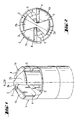
- Fig. 1, 2 has the head end of a rotating drivable, small concrete drill a cutting part 1 and one of these, at Fig. 2 normal to the plane of representation, limited axially movable impact member 2, wherein the respective working areas of the cutting part and the impact part overlap radially upon rotation radially from a small center region to the total Bohrradius.
- the impact part 2 and the cutting part 1 are in the transverse plane segmentally formed with two impact segments 2a, 2b and two cutting segments 1a, 1b nested, with circumferentially adjacent, in the center region interconnected impact segments 2a, 2b with the cutting segments 1a, 1b common, axially extending Form intermediate segment surfaces 3.
- the hard cutting inserts 4 with layers of polycrystalline diamonds (PCD) formed sharp cutting edges of the cutting segments 1 a, 1 b have a rake angle of 0 °, each of which large-area segment-like free spaces 5 are upstream in Drehrichrtung.
- PCD polycrystalline diamonds
- FIG. 3a . 3b forms the cutting part 1 and the impact member 2 shown in an axial intermediate position of PCD-coated hard metal on rotation of a substantially common slightly curved Hüllkopf Design 6 at the head end, which processes the associated borehole surface 7.
- a rotatably connected to the cutting part 1 drill shank 8 is formed as a hollow cylinder.
- the impact member 1 is associated with a separately axially limited in the drill shank 8 axially movably guided plunger 9, wherein extending longitudinally between them, the free space 5.
- the cutting part 1 is connected via the drill shank 8 limited axially movable with a spigot 10, which has rotary driving grooves 11 and axially closed locking grooves 12.
- the free space 5 is connected to suction openings 13 in the drill shank 8.
- the cutting part 1 is about the drill shank 8 z. B. with a coil spring as a spring means 14 axially resiliently biased against the insertion end 10.
Landscapes
- Engineering & Computer Science (AREA)
- Mining & Mineral Resources (AREA)
- Mechanical Engineering (AREA)
- Geology (AREA)
- Life Sciences & Earth Sciences (AREA)
- Fluid Mechanics (AREA)
- Environmental & Geological Engineering (AREA)
- Physics & Mathematics (AREA)
- General Life Sciences & Earth Sciences (AREA)
- Geochemistry & Mineralogy (AREA)
- Processing Of Stones Or Stones Resemblance Materials (AREA)
- Drilling Tools (AREA)
- Polishing Bodies And Polishing Tools (AREA)
- Earth Drilling (AREA)
- Curing Cements, Concrete, And Artificial Stone (AREA)
Description
- Die Erfindung bezeichnet einen drehend und schlagend von einer Handwerkzeugmaschine antreibbaren Betonbohrer mit Hartstoffeinsätzen.
- Üblicherweise sind von einer Handwerkzeugmaschine antreibbare kleine Betonbohrer bis zum Bohrdurchmesser von 40 mm, auf welche sich diese Erfindung beschränkt, entweder einteilig als Hammerbohrer mit einem festen Bohrkopf mit Hartstoffeinsätzen oder zweiteilig mit einem relativ zum Bohrerschaft axial begrenzt beweglichen Bohrkopf mit Hartstoffeinsätzen ausgebildet. Derartige schlagend und drehend beanspruchte Hartstoffeinsätze weisen üblicherweise eine stumpfe Schneide mit einem Schneidradius grösser 1/20 des Bohrdurchmessers sowie einen negativen Spanwinkel von -25° bis -45° auf, wodurch hohe Schlagenergien für den dominierenden, zermürbenden Abbauprozess notwendig sind und sich in Beton eingebettete Armierungseisen nur uneffizient bohren lassen. Der durch die hohen Schlagenergien erzeugte grosse Luft- und Körperschall ist insbesondere im Bauhaupt- und Nebengewerbe
- Nach der
US4852672 weist ein kleiner Betonbohrer einen rein drehenden Schneidteil und einen, separat im Bohrerschaft geführten, Schlagteil auf, welcher etwas axial voreilend eine Pilotbohrung zur Entspannung der Bohrlochfläche erstellt. Nach derDE19748987 ist ein grosser Gesteinsbohrer mit einem, mit Hartstoffzähnen besetzten, rein drehenden Schneidteil und einem, nach der zudemDE19950599 separat von einem im Bohrerschaft innenliegenden Stössel anstossbaren, Schlagteil ausgeführt, welcher etwas axial voreilend eine Pilotbohrung zur Entspannung der Bohrlochfläche erstellt. Durch diese räumliche Funktionstrennung wirkt auf einen Feinstrukturbereich in der Bohrlochfläche stets nur ein und derselbe Abbauprozess ein. - Die
US 1863928 bildet den Oberbegriff für Anspruch 1 und zeigt einen zum Bohren tiefer Brunnen drehend und schlagend angetriebenen Bohrer grossen Durchsmessers mit einem Schneidteil und einem zu diesem begrenzt axial beweglichen Schlagteil, welche jeweils stirnflächige Arbeitsbereiche zur Bearbeitung einer Bohrlochfläche aufweisen, wobei sich die jeweiligen stirnflächigen Arbeitsbereiche des Schneidteils und des Schlagteils bei Drehung des Bohrers radial überlagern. - Die Aufgabe der Erfindung besteht in der Realisierung eines von einer Handwerkzeugmaschine antreibbaren kleinen Betonbohrers mit effizienter Bohrleistung in armierten und nichtarmierten Beton. Ein weiterer Aspekt besteht in der Verringerung der benötigten Schlagenergien.
- Die Aufgabe wird im Wesentlichen durch die Merkmale des unabhängigen Anspruchs gelöst. Vorteilhafte Weiterbildungen ergeben sich aus den Unteransprüchen.
- Im Wesentlichen weist ein drehend antreibbarer, kleiner Betonbohrer einen Schneidteil und einen zu diesen begrenzt axial beweglichen Schlagteil auf, welche jeweils stirnflächige Arbeitsbereiche zur Bearbeitung einer Bohrlochfläche aufweisen, wobei sich die jeweiligen stirnflächigen Arbeitsbereiche des Schneidteils und des Schlagteils bei Drehung radial überlagern.
- Durch die radiale Überlagerung der stirnflächigen Arbeitsbereiche wird der zugeordnete Teil der Bohrlochfläche bei der Drehung des Betonbohrers alternierend vom Schlagteil und vom Schneidteil bearbeitet, wodurch zeitlich alternierend zwei verschiedene Abbauprozesse in der Bohrlochfläche wirken, wobei der rammende Schlagteil in einem axialen Feinstrukturbereich von 0,1 mm - 1,0 mm eine Schädigungszone vorschädigt, in welcher die zum spanenden Abtrag notwendigen Zerspankräfte( Normal- und Schittkraft) wesentlich geringer als im nicht vorgeschädigten Material sind. Entsprechende Experimente belegen eine Absenkung der Zerspankräfte um bis zu 80°. Der somit im wesentlichen spanend erfolgende Abtrag ist effizient sowohl in armierten und nichtarmierten Beton. Durch die mögliche Absenkung der Schlagenergien verringert sich der Luft-und Körperschall. Ebenso können die antreibenden Handwerkzeugmaschinen kleiner, leichter und vibrationsärmer ausgeführt werden.
- Vorteilhaft überlagern sich die Arbeitsbereiche bei Drehung radial von einem kleinen Zentrumsbereich bis zum Gesamtbohrradius, wodurch nahezu die gesamte Vollbohrung alternierend mit zwei verschiedenen Abbauprozessen bearbeitet wird.
- Vorteilhaft bildet in einer Zwischenposition des Schlagteils das Schneidteil und das Schlagteil bei Drehung eine im wesentlichen gemeinsame ebene, leicht gewölbte oder leicht kegelige Hüllkopffläche am kopfseitigen Stirnende aus, wodurch bei wiederholter Schlagbeanspruchung das Schneidteil und das Schlagteils alternierend bezüglich der Bohrlochfläche entlastet sind, wodurch die beiden verschiedenen Abbauprozesse vollständig entkoppelt sind.
- Zumindest am kopfseitigen Stirnende sind das Schlagteil und das Schneidteil in der Querebene segmentartig mit mindestens zwei Schlagsegmenten und mindestens zwei Schneidsegmenten ineinander verschachtelt ausgebildet, wodurch bei einer Umdrehung des Betonbohrers das Schlagteil und das Schneidteil mehrfach alternierend einem Feinstrukturbereich in der Bohrlochfläche bearbeitend zugeordnet ist.
- Wesentlich ist, dass umfänglich benachbarte Schlagsegmente und Schneidsegmente gemeinsame, axial verlaufenden Zwischensegmentflächen ausbilden, wodurch eine einfache gegenseitige Axialführung und Drehmitnahme der Schlagsegmente realisiert ist.
- Vorteilhaft sind zumindest zwei Schlagsegmente am kopfseitigen Stirnende des Schlagteils miteinander verbunden, wodurch diese eine belastbarere Geometrie aufweist.
- Vorteilhaft sind genau zwei diametral gegenüberliegende, miteinander verbundene Schlagsegmente in genau zwei diametral gegenüberliegenden, am kopfseitigen Stirnende unverbundenen, Schneidsegmenten verschachtelt angeordnet, wodurch bei gegenseitiger Führung ein relativ kompakter und somit hoch belastbarer Schlagteil realisierbar ist.
- Vorteilhaft weisen die Schneidkanten des Schneidteils bzw. Schneidsegments einen Schneidradius kleiner 1/20 des Bohrdurchmessers und weiter vorteilhaft einen Spanwinkel im Bereich (-10° bis +120°) auf, wodurch diese auf einen zerspanenden Abbauprozess optimiert sind und hinreichend gut Armierungseisen schneiden.
- Vorteilhaft sind die Schneidkanten durch Hartstoffeinsätze, weiter vorteilhaft durch Hartstoffeinsätze mit Schichten aus polykristalline Diamanten (PKD) ausgebildet, welcher weniger verschleissen und somit eine höhere Lebensdauer aufweisen.
- Vorteilhaft ist dem Schlagteil ein separat im Bohrerschaft axial begrenzt beweglich geführter Stössel zugeordnet, wodurch ein durch diesen axial laufender, steiler Stossimpuls reflektionsarm und somit nahezu vollständig auf das Schlagteil übertragbar ist, welcher in die Bohrlochfläche rammt und diese im Feinstrukturbereich vorschädigt.
- Vorteilhaft ist der Schlagteil aus einem sehr verschleissfesten Material ausgeführt bspw. aus einem PKD-beschichteten kalottenförmigen Hartmetallträger, wodurch die Lebensdauer des Schlagteils erhöht wird.
- Vorteilhaft ist das Schneidteil zu einem Einsteckende zur Aufnahme in eine Handwerkzeugmaschine begrenzt axial beweglich gelagert, wodurch es vollständig von schlagender Beanspruchung entkoppelt ist, wodurch die Schneiden weniger beansprucht werden und eine höhere Lebensdauer aufweisen.
- Vorteilhaft ist das Schneidteil, weiter vorteilhaft der Bohrerschaft, mit einem Federmittel axial federnd gegen das Einsteckende vorgespannt, wodurch eine definierte Normalkraft des Scheidteils auf das Werkstück realisiert wird.
- Vorteilhaft weist der Querschnitt durch das kopfseitige Stirnende, weiter vorteilhaft grossflächige segmentartige, Freiräume auf, wodurch der Abbrieb aus dem Bohrloch abtransportierbar ist.
- Vorteilhaft ist ein mit dem Schneidteil drehfest verbunder Bohrerschaft als Hohlzylinder ausgebildet, wodurch der Abbrieb aus dem Bohrloch im Schaftinneren absaugbar ist.
- Die Erfindung wird bezüglich eines vorteilhaften Ausführungsbeispiels näher erläutert mit:
-
Fig. 1 als perspektivische Darstellung des kopfseitigen Stirnendes des Betonbohrers -
Fig. 2 als Draufsicht auf das kopfseitige Stirnendes des Betonbohrers -
Fig. 3a ,3b als um 90° versetzte Längsschnitte - Nach den
Fig. 1, 2 weist das kopfseitige Stirnende eines drehend antreibbaren, kleinen Betonbohrers einen Schneidteil 1 und einen zu diesen, beiFig. 2 normal zur Darstellungsebene, begrenzt axial beweglichen Schlagteil 2 auf, wobei sich die jeweiligen Arbeitsbereiche des Schneidteils und des Schlagteils bei Drehung radial von einem kleinen Zentrumsbereich bis zum Gesamtbohrradius überlagern. Das Schlagteil 2 und das Schneidteil 1 sind in der Querebene segmentartig mit zwei Schlagsegmenten 2a, 2b und zwei Schneidsegmenten 1a, 1b ineinander verschachtelt ausgebildet, wobei umfänglich benachbarte, im Zentrumsbereich miteinander verbundene Schlagsegmente 2a, 2b mit den Schneidsegmenten 1a, 1b gemeinsame, axial verlaufenden Zwischensegmentflächen 3 ausbilden. Die aus Hartstoffeinsätzen 4 mit Schichten aus polykristalline Diamanten (PKD) ausgebildeten scharfen Schneidkanten der Schneidsegmente 1a, 1b weisen einen Spanwinkel von 0° auf, denen jeweils in Drehrichrtung grossflächige segmentartige Freiräume 5 vorgelagert sind. - Nach den
Fig. 3a ,3b bildet das Schneidteil 1 und das in einer axialen Zwischenposition dargestellte Schlagteil 2 aus PKD-beschichteten Hartmetall bei Drehung eine im wesentlichen gemeinsame leicht gewölbte Hüllkopffläche 6 am kopfseitigen Stirnende aus, welche die zugeordnete Bohrlochfläche 7 bearbeitet. Ein mit dem Schneidteil 1 drehfest verbundener Bohrerschaft 8 ist als Hohlzylinder ausgebildet. Dem Schlagteil 1 ist ein separat im Bohrerschaft 8 axial begrenzt beweglich geführter Stössel 9 zugeordnet, wobei sich längs durchgehend zwischen diesen der Freiraum 5 erstreckt. NachFig. 3a ist das Schneidteil 1 über den Bohrerschaft 8 begrenzt axial beweglich mit einem Einsteckende 10 verbunden, welches Drehmitnahmenuten 11 und axial geschlossene Verriegelungsnuten 12 aufweist. - Der Freiraum 5 ist mit Absaugöffnungen 13 im Bohrerschaft 8 verbunden. Das Schneidteil 1 ist über den Bohrerschaft 8 z. B. mit einer Spiralfeder als Federmittel 14 axial federnd gegen das Einsteckende 10 vorgespannt.
Claims (13)
- Betonbohrer für eine drehend und schlagend antreibende Handwerkzeugmaschine mit einem Schneidteil (1) und einem zu diesem begrenzt axial beweglichen Schlagteil (2), welche jeweils stirnflächige Arbeitsbereiche zur Bearbeitung einer Bohrlochfläche (7) aufweisen, wobei sich die jeweiligen stirnflächigen Arbeitsbereiche des Schneidteils (1) und des Schlagteils (2) bei Drehung des Betonbohrers radial überlagern und zumindest am kopfseitigen Stirnende das Schlagteil (2) und das Schneidteil (1) in der Querebene segmentartig mit mindestens zwei Schlagsegmenten (2a, 2b) und mindestens zwei Schneidsegmenten (1a, 1 b) ineinander verschachtelt ausgebildet sind,
dadurch gekennzeichnet, dass umfänglich benachbarte Schlagsegmente (2a, 2b) und Schneidsegmente (1a, 1b) gemeinsame, axial verlaufenden Zwischensegmentflächen (3) ausbilden. - Betonbohrer nach Anspruch 1, dadurch gekennzeichnet, dass sich die Arbeitsbereiche bei Drehung radial von einem kleinen Zentrumsbereich bis zum Gesamtbohrradius überlagern.
- Betonbohrer nach Anspruch 1 oder 2, dadurch gekennzeichnet, dass in einer axialen Zwischenposition des Schlagteils (2) das Schneidteil (1) und das Schlagteil (2) bei Drehung eine im wesentlichen gemeinsame Hüllkopffläche (6) am kopfseitigen Stirnende ausbilden.
- Betonbohrer nach einem der vorherigen Ansprüche, dadurch gekennzeichnet, dass zumindest zwei Schlagsegmente (2a, 2b) am kopfseitigen Stirnende des Schlagteils (2) miteinander verbunden sind.
- Betonbohrer nach Anspruch 4, dadurch gekennzeichnet, dass genau zwei diametral gegenüberliegende, miteinander verbundene Schlagsegmente (2a, 2b) in genau zwei diametral gegenüberliegenden, am kopfseitigen Stirnende unverbundenen, Schneidsegmenten (1 a, 1 b) verschachtelt angeordnet sind.
- Betonbohrer nach einem der vorherigen Ansprüche, dadurch gekennzeichnet, dass die Schneidkanten des Schneidteils (1) bzw. Schneidsegments (1a, 1b) einen Schneidradius kleiner 1/20 des Bohrdurchmessers und optional einen Spanwinkel im Bereich -10° bis +10° aufweisen.
- Betonbohrer nach Anspruch 4, dadurch gekennzeichnet, dass die Schneidkanten durch Hartstoffeinsätze (4) ausgebildet sind, und dass optional die Hartstoffeinsätze (4) Schichten aus polykristallinen Diamanten (PKD) aufweisen.
- Betonbohrer nach einem der vorherigen Ansprüche, dadurch gekennzeichnet, dass dem Schlagteil (2) ein separat im Bohrerschaft (8) axial begrenzt beweglich geführter Stössel (9) zugeordnet ist.
- Betonbohrer nach einem der vorherigen Ansprüche, dadurch gekennzeichnet, dass der Schlagteil (2) aus einem sehr verschleissfesten Material ausgeführt ist.
- Betonbohrer nach einem der vorherigen Ansprüche, dadurch gekennzeichnet, dass das Schneidteil (1) zu einem Einsteckende (10) zur Aufnahme in eine Handwerkzeugmaschine begrenzt axial beweglich gelagert ist.
- Betonbohrer nach Anspruch 10, dadurch gekennzeichnet, dass das Schneidteil (1) mit einem Federmittel (14) axial federnd gegen das Einsteckende (10) vorgespannt ist.
- Betonbohrer nach einem der vorherigen Ansprüche, dadurch gekennzeichnet, dass das kopfseitige Stirnende in der Querebene zumindest einen Freiraum (5) aufweist, welcher optional grossflächig segmentartig ausgebildet ist.
- Betonbohrer nach einem der vorherigen Ansprüche, dadurch gekennzeichnet, dass ein mit dem Schneidteil (1) drehfest verbundener Bohrerschaft (8) als Hohlzylinder ausgebildet ist.
Applications Claiming Priority (2)
| Application Number | Priority Date | Filing Date | Title |
|---|---|---|---|
| DE10232214A DE10232214C1 (de) | 2002-07-17 | 2002-07-17 | Betonbohrer |
| DE10232214 | 2002-07-17 |
Publications (2)
| Publication Number | Publication Date |
|---|---|
| EP1382409A1 EP1382409A1 (de) | 2004-01-21 |
| EP1382409B1 true EP1382409B1 (de) | 2008-02-20 |
Family
ID=29594618
Family Applications (1)
| Application Number | Title | Priority Date | Filing Date |
|---|---|---|---|
| EP03102055A Expired - Lifetime EP1382409B1 (de) | 2002-07-17 | 2003-07-09 | Betonbohrer |
Country Status (9)
| Country | Link |
|---|---|
| US (1) | US7055633B2 (de) |
| EP (1) | EP1382409B1 (de) |
| AT (1) | ATE386601T1 (de) |
| AU (1) | AU2003213305B2 (de) |
| DE (2) | DE10232214C1 (de) |
| DK (1) | DK1382409T3 (de) |
| ES (1) | ES2298473T3 (de) |
| HU (1) | HUP0302228A2 (de) |
| ZA (1) | ZA200305488B (de) |
Families Citing this family (12)
| Publication number | Priority date | Publication date | Assignee | Title |
|---|---|---|---|---|
| DE102008019933A1 (de) * | 2008-04-21 | 2009-10-22 | Ford Global Technologies, LLC, Dearborn | Vorrichtung und Verfahren zum Vorbereiten einer Oberfläche aus Metall für das Aufbringen einer thermisch gespritzten Schicht |
| DE102008054869B4 (de) * | 2008-12-18 | 2010-09-02 | Hilti Aktiengesellschaft | Bohrkopf für Gesteinsbohrer |
| DE102011006015A1 (de) * | 2011-03-24 | 2012-09-27 | Hilti Aktiengesellschaft | Gewindeschneidsystem |
| DE102011086803A1 (de) | 2011-11-22 | 2013-05-23 | Ford Global Technologies, Llc | Reparaturverfahren einer Zylinderlauffläche mittels Plasmaspritzverfahren |
| DE102013200912B4 (de) | 2012-02-02 | 2018-05-30 | Ford Global Technologies, Llc | Kurbelgehäuse |
| US8726874B2 (en) * | 2012-05-01 | 2014-05-20 | Ford Global Technologies, Llc | Cylinder bore with selective surface treatment and method of making the same |
| US9511467B2 (en) * | 2013-06-10 | 2016-12-06 | Ford Global Technologies, Llc | Cylindrical surface profile cutting tool and process |
| US9079213B2 (en) | 2012-06-29 | 2015-07-14 | Ford Global Technologies, Llc | Method of determining coating uniformity of a coated surface |
| USD734790S1 (en) * | 2013-06-12 | 2015-07-21 | Element Six (Production) (Pty) Ltd | Drill bit tip |
| US9382868B2 (en) | 2014-04-14 | 2016-07-05 | Ford Global Technologies, Llc | Cylinder bore surface profile and process |
| US10220453B2 (en) | 2015-10-30 | 2019-03-05 | Ford Motor Company | Milling tool with insert compensation |
| DE102017219452A1 (de) * | 2017-10-30 | 2019-05-02 | Robert Bosch Gmbh | Bohrwerkzeug |
Family Cites Families (12)
| Publication number | Priority date | Publication date | Assignee | Title |
|---|---|---|---|---|
| US1863928A (en) * | 1931-05-09 | 1932-06-21 | James A Macdonell | Combination percussion and rotary drill |
| DE732395C (de) * | 1939-01-22 | 1943-03-01 | Alfred Heger Jun | Durch Schlag zu betaetigender Steinbohrer |
| US2859941A (en) * | 1956-02-06 | 1958-11-11 | Martin B Carroll | Combination rotary and impact drill |
| GB1067975A (en) * | 1964-03-10 | 1967-05-10 | Sandvikens Jernverks Ab | Adapter device for percussion drill |
| US3842920A (en) * | 1973-02-19 | 1974-10-22 | Gonzalez E Barnetche | Percussion tools |
| DE7912337U1 (de) * | 1979-04-27 | 1979-07-26 | Hawera Probst Gmbh + Co, 7980 Ravensburg | Gesteinsbohrkrone |
| US4852672A (en) * | 1988-08-15 | 1989-08-01 | Behrens Robert N | Drill apparatus having a primary drill and a pilot drill |
| JP2598515B2 (ja) * | 1989-04-24 | 1997-04-09 | 株式会社ミヤナガ | 拡径部付孔穿孔装置 |
| DE9211782U1 (de) * | 1991-11-19 | 1993-03-18 | Eischeid, Karl, 5250 Engelskirchen | Bohrer |
| DE19748987B4 (de) * | 1997-11-06 | 2007-11-22 | Robert Bosch Gmbh | Bohrwerkzeug insbesondere für drehschlagendes Bohren von vorzugsweise Gestein |
| DE19950599A1 (de) * | 1999-09-17 | 2001-03-22 | Klemm Bohrtechnik Zweigniederl | Bohrwerkzeug in Form einer Felsbohrschnecke mit Imlochhammer |
| DE20021710U1 (de) * | 2000-12-22 | 2001-03-22 | Drebo Werkzeugfabrik Gmbh, 88361 Altshausen | Gesteinsbohrer |
-
2002
- 2002-07-17 DE DE10232214A patent/DE10232214C1/de not_active Expired - Fee Related
-
2003
- 2003-07-09 EP EP03102055A patent/EP1382409B1/de not_active Expired - Lifetime
- 2003-07-09 ES ES03102055T patent/ES2298473T3/es not_active Expired - Lifetime
- 2003-07-09 DK DK03102055T patent/DK1382409T3/da active
- 2003-07-09 DE DE50309189T patent/DE50309189D1/de not_active Expired - Lifetime
- 2003-07-09 AT AT03102055T patent/ATE386601T1/de not_active IP Right Cessation
- 2003-07-14 AU AU2003213305A patent/AU2003213305B2/en not_active Ceased
- 2003-07-16 US US10/620,486 patent/US7055633B2/en not_active Expired - Fee Related
- 2003-07-16 ZA ZA200305488A patent/ZA200305488B/xx unknown
- 2003-07-16 HU HU0302228A patent/HUP0302228A2/hu unknown
Also Published As
| Publication number | Publication date |
|---|---|
| US7055633B2 (en) | 2006-06-06 |
| DE50309189D1 (de) | 2008-04-03 |
| US20040079556A1 (en) | 2004-04-29 |
| EP1382409A1 (de) | 2004-01-21 |
| AU2003213305A1 (en) | 2004-02-05 |
| DK1382409T3 (da) | 2008-06-23 |
| ES2298473T3 (es) | 2008-05-16 |
| HUP0302228A2 (hu) | 2004-05-28 |
| AU2003213305B2 (en) | 2007-09-06 |
| ZA200305488B (en) | 2004-05-19 |
| DE10232214C1 (de) | 2003-12-24 |
| HU0302228D0 (en) | 2003-09-29 |
| ATE386601T1 (de) | 2008-03-15 |
Similar Documents
| Publication | Publication Date | Title |
|---|---|---|
| EP1125664B1 (de) | Bohrwerkzeug für Gestein | |
| DE10232214C1 (de) | Betonbohrer | |
| EP1602452B1 (de) | Einsteckende für ein drehendes und/oder schlagendes Werkzeug | |
| EP1125663A2 (de) | Bohrwerkzeug für Gestein | |
| DE3407427A1 (de) | Bohrkrone | |
| EP0937860B1 (de) | Bohr- und/oder Meisselwerkzeug | |
| EP1923160B1 (de) | Bohrwerkzeug mit Hartstoffkopf | |
| EP1537956B1 (de) | Einsteckende für ein drehendes und/oder schlagendes Werkzeug | |
| WO2019086212A1 (de) | Bohrwerkzeug | |
| EP1083295B1 (de) | Bohrwerkzeug | |
| EP1923159A1 (de) | Bohrwerkzeug mit Hartstoffkopf | |
| EP1184535A2 (de) | Gesteinsbohrer | |
| DE2423510A1 (de) | Gesteinsbohrer | |
| DE10306645B3 (de) | Schlagdrehbohrer mit Hartstoffschneiden | |
| DE10103143B4 (de) | Gesteinsbohrer | |
| EP0965405B1 (de) | Bohrwerkzeug | |
| DE2917292C2 (de) | Werkzeug zur Herstellung von Gesteinsbohrungen | |
| DE2430519A1 (de) | Steinbrechvorrichtung | |
| EP1923158B1 (de) | Bohrwerkzeug mit Hartstoffeinsatz | |
| EP0825003A2 (de) | Fräsmaschine mit rotierendem Fräswerkzeug für gesteinsartige Materialien | |
| DE4101458A1 (de) | Fuer einen mit axialem druck und schlaegen arbeitenden, umlaufenden gesteinsbohrer bestimmter bohrmeissel | |
| DE245750C (de) | ||
| DE102011075040B4 (de) | Bohrer und Zubehör für einen Bohrer | |
| EP1242216A1 (de) | Schlagunterstützte handbohrmaschine | |
| WO2013053542A1 (de) | Hammerbohrkrone |
Legal Events
| Date | Code | Title | Description |
|---|---|---|---|
| PUAI | Public reference made under article 153(3) epc to a published international application that has entered the european phase |
Free format text: ORIGINAL CODE: 0009012 |
|
| AK | Designated contracting states |
Kind code of ref document: A1 Designated state(s): AT BE BG CH CY CZ DE DK EE ES FI FR GB GR HU IE IT LI LU MC NL PT RO SE SI SK TR |
|
| AX | Request for extension of the european patent |
Extension state: AL LT LV MK |
|
| 17P | Request for examination filed |
Effective date: 20040721 |
|
| AKX | Designation fees paid |
Designated state(s): AT BE BG CH CY CZ DE DK EE ES FI FR GB GR HU IE IT LI LU MC NL PT RO SE SI SK TR |
|
| GRAP | Despatch of communication of intention to grant a patent |
Free format text: ORIGINAL CODE: EPIDOSNIGR1 |
|
| GRAS | Grant fee paid |
Free format text: ORIGINAL CODE: EPIDOSNIGR3 |
|
| GRAA | (expected) grant |
Free format text: ORIGINAL CODE: 0009210 |
|
| AK | Designated contracting states |
Kind code of ref document: B1 Designated state(s): AT BE BG CH CY CZ DE DK EE ES FI FR GB GR HU IE IT LI LU MC NL PT RO SE SI SK TR |
|
| REG | Reference to a national code |
Ref country code: GB Ref legal event code: FG4D Free format text: NOT ENGLISH |
|
| REG | Reference to a national code |
Ref country code: CH Ref legal event code: EP |
|
| REG | Reference to a national code |
Ref country code: IE Ref legal event code: FG4D Free format text: LANGUAGE OF EP DOCUMENT: GERMAN |
|
| REF | Corresponds to: |
Ref document number: 50309189 Country of ref document: DE Date of ref document: 20080403 Kind code of ref document: P |
|
| REG | Reference to a national code |
Ref country code: ES Ref legal event code: FG2A Ref document number: 2298473 Country of ref document: ES Kind code of ref document: T3 |
|
| REG | Reference to a national code |
Ref country code: DK Ref legal event code: T3 |
|
| PG25 | Lapsed in a contracting state [announced via postgrant information from national office to epo] |
Ref country code: FI Free format text: LAPSE BECAUSE OF FAILURE TO SUBMIT A TRANSLATION OF THE DESCRIPTION OR TO PAY THE FEE WITHIN THE PRESCRIBED TIME-LIMIT Effective date: 20080220 |
|
| NLV1 | Nl: lapsed or annulled due to failure to fulfill the requirements of art. 29p and 29m of the patents act | ||
| PG25 | Lapsed in a contracting state [announced via postgrant information from national office to epo] |
Ref country code: SI Free format text: LAPSE BECAUSE OF FAILURE TO SUBMIT A TRANSLATION OF THE DESCRIPTION OR TO PAY THE FEE WITHIN THE PRESCRIBED TIME-LIMIT Effective date: 20080220 |
|
| REG | Reference to a national code |
Ref country code: IE Ref legal event code: FD4D |
|
| ET | Fr: translation filed | ||
| PG25 | Lapsed in a contracting state [announced via postgrant information from national office to epo] |
Ref country code: IE Free format text: LAPSE BECAUSE OF FAILURE TO SUBMIT A TRANSLATION OF THE DESCRIPTION OR TO PAY THE FEE WITHIN THE PRESCRIBED TIME-LIMIT Effective date: 20080220 Ref country code: SK Free format text: LAPSE BECAUSE OF FAILURE TO SUBMIT A TRANSLATION OF THE DESCRIPTION OR TO PAY THE FEE WITHIN THE PRESCRIBED TIME-LIMIT Effective date: 20080220 Ref country code: PT Free format text: LAPSE BECAUSE OF FAILURE TO SUBMIT A TRANSLATION OF THE DESCRIPTION OR TO PAY THE FEE WITHIN THE PRESCRIBED TIME-LIMIT Effective date: 20080721 Ref country code: NL Free format text: LAPSE BECAUSE OF FAILURE TO SUBMIT A TRANSLATION OF THE DESCRIPTION OR TO PAY THE FEE WITHIN THE PRESCRIBED TIME-LIMIT Effective date: 20080220 Ref country code: SE Free format text: LAPSE BECAUSE OF FAILURE TO SUBMIT A TRANSLATION OF THE DESCRIPTION OR TO PAY THE FEE WITHIN THE PRESCRIBED TIME-LIMIT Effective date: 20080520 Ref country code: CZ Free format text: LAPSE BECAUSE OF FAILURE TO SUBMIT A TRANSLATION OF THE DESCRIPTION OR TO PAY THE FEE WITHIN THE PRESCRIBED TIME-LIMIT Effective date: 20080220 |
|
| PGFP | Annual fee paid to national office [announced via postgrant information from national office to epo] |
Ref country code: CH Payment date: 20080912 Year of fee payment: 6 Ref country code: DK Payment date: 20080721 Year of fee payment: 6 Ref country code: ES Payment date: 20080821 Year of fee payment: 6 |
|
| PG25 | Lapsed in a contracting state [announced via postgrant information from national office to epo] |
Ref country code: RO Free format text: LAPSE BECAUSE OF FAILURE TO SUBMIT A TRANSLATION OF THE DESCRIPTION OR TO PAY THE FEE WITHIN THE PRESCRIBED TIME-LIMIT Effective date: 20080220 |
|
| PGFP | Annual fee paid to national office [announced via postgrant information from national office to epo] |
Ref country code: AT Payment date: 20080711 Year of fee payment: 6 Ref country code: IT Payment date: 20080729 Year of fee payment: 6 |
|
| PLBE | No opposition filed within time limit |
Free format text: ORIGINAL CODE: 0009261 |
|
| STAA | Information on the status of an ep patent application or granted ep patent |
Free format text: STATUS: NO OPPOSITION FILED WITHIN TIME LIMIT |
|
| 26N | No opposition filed |
Effective date: 20081121 |
|
| PG25 | Lapsed in a contracting state [announced via postgrant information from national office to epo] |
Ref country code: MC Free format text: LAPSE BECAUSE OF NON-PAYMENT OF DUE FEES Effective date: 20080731 |
|
| PG25 | Lapsed in a contracting state [announced via postgrant information from national office to epo] |
Ref country code: EE Free format text: LAPSE BECAUSE OF FAILURE TO SUBMIT A TRANSLATION OF THE DESCRIPTION OR TO PAY THE FEE WITHIN THE PRESCRIBED TIME-LIMIT Effective date: 20080220 Ref country code: BG Free format text: LAPSE BECAUSE OF FAILURE TO SUBMIT A TRANSLATION OF THE DESCRIPTION OR TO PAY THE FEE WITHIN THE PRESCRIBED TIME-LIMIT Effective date: 20080520 |
|
| PG25 | Lapsed in a contracting state [announced via postgrant information from national office to epo] |
Ref country code: CY Free format text: LAPSE BECAUSE OF FAILURE TO SUBMIT A TRANSLATION OF THE DESCRIPTION OR TO PAY THE FEE WITHIN THE PRESCRIBED TIME-LIMIT Effective date: 20080220 |
|
| REG | Reference to a national code |
Ref country code: CH Ref legal event code: PL |
|
| REG | Reference to a national code |
Ref country code: DK Ref legal event code: EBP |
|
| PG25 | Lapsed in a contracting state [announced via postgrant information from national office to epo] |
Ref country code: LI Free format text: LAPSE BECAUSE OF NON-PAYMENT OF DUE FEES Effective date: 20090731 Ref country code: CH Free format text: LAPSE BECAUSE OF NON-PAYMENT OF DUE FEES Effective date: 20090731 |
|
| PG25 | Lapsed in a contracting state [announced via postgrant information from national office to epo] |
Ref country code: AT Free format text: LAPSE BECAUSE OF NON-PAYMENT OF DUE FEES Effective date: 20090709 |
|
| PG25 | Lapsed in a contracting state [announced via postgrant information from national office to epo] |
Ref country code: LU Free format text: LAPSE BECAUSE OF NON-PAYMENT OF DUE FEES Effective date: 20080709 Ref country code: HU Free format text: LAPSE BECAUSE OF FAILURE TO SUBMIT A TRANSLATION OF THE DESCRIPTION OR TO PAY THE FEE WITHIN THE PRESCRIBED TIME-LIMIT Effective date: 20080821 Ref country code: DK Free format text: LAPSE BECAUSE OF NON-PAYMENT OF DUE FEES Effective date: 20090731 Ref country code: BE Free format text: LAPSE BECAUSE OF NON-PAYMENT OF DUE FEES Effective date: 20080731 |
|
| PG25 | Lapsed in a contracting state [announced via postgrant information from national office to epo] |
Ref country code: TR Free format text: LAPSE BECAUSE OF FAILURE TO SUBMIT A TRANSLATION OF THE DESCRIPTION OR TO PAY THE FEE WITHIN THE PRESCRIBED TIME-LIMIT Effective date: 20080220 |
|
| REG | Reference to a national code |
Ref country code: ES Ref legal event code: FD2A Effective date: 20090710 |
|
| PG25 | Lapsed in a contracting state [announced via postgrant information from national office to epo] |
Ref country code: ES Free format text: LAPSE BECAUSE OF NON-PAYMENT OF DUE FEES Effective date: 20090710 Ref country code: GR Free format text: LAPSE BECAUSE OF FAILURE TO SUBMIT A TRANSLATION OF THE DESCRIPTION OR TO PAY THE FEE WITHIN THE PRESCRIBED TIME-LIMIT Effective date: 20080521 |
|
| PG25 | Lapsed in a contracting state [announced via postgrant information from national office to epo] |
Ref country code: IT Free format text: LAPSE BECAUSE OF NON-PAYMENT OF DUE FEES Effective date: 20090709 |
|
| PGFP | Annual fee paid to national office [announced via postgrant information from national office to epo] |
Ref country code: GB Payment date: 20120704 Year of fee payment: 10 |
|
| PGFP | Annual fee paid to national office [announced via postgrant information from national office to epo] |
Ref country code: FR Payment date: 20120719 Year of fee payment: 10 Ref country code: DE Payment date: 20120613 Year of fee payment: 10 |
|
| GBPC | Gb: european patent ceased through non-payment of renewal fee |
Effective date: 20130709 |
|
| REG | Reference to a national code |
Ref country code: FR Ref legal event code: ST Effective date: 20140331 |
|
| PG25 | Lapsed in a contracting state [announced via postgrant information from national office to epo] |
Ref country code: DE Free format text: LAPSE BECAUSE OF NON-PAYMENT OF DUE FEES Effective date: 20140201 Ref country code: GB Free format text: LAPSE BECAUSE OF NON-PAYMENT OF DUE FEES Effective date: 20130709 |
|
| REG | Reference to a national code |
Ref country code: DE Ref legal event code: R119 Ref document number: 50309189 Country of ref document: DE Effective date: 20140201 |
|
| PG25 | Lapsed in a contracting state [announced via postgrant information from national office to epo] |
Ref country code: FR Free format text: LAPSE BECAUSE OF NON-PAYMENT OF DUE FEES Effective date: 20130731 |