EP1381251A2 - Speaker and speaker diaphragm - Google Patents
Speaker and speaker diaphragm Download PDFInfo
- Publication number
- EP1381251A2 EP1381251A2 EP03253944A EP03253944A EP1381251A2 EP 1381251 A2 EP1381251 A2 EP 1381251A2 EP 03253944 A EP03253944 A EP 03253944A EP 03253944 A EP03253944 A EP 03253944A EP 1381251 A2 EP1381251 A2 EP 1381251A2
- Authority
- EP
- European Patent Office
- Prior art keywords
- speaker
- edge portion
- diaphragm
- regulation member
- main body
- Prior art date
- Legal status (The legal status is an assumption and is not a legal conclusion. Google has not performed a legal analysis and makes no representation as to the accuracy of the status listed.)
- Withdrawn
Links
Images


Classifications
-
- H—ELECTRICITY
- H04—ELECTRIC COMMUNICATION TECHNIQUE
- H04R—LOUDSPEAKERS, MICROPHONES, GRAMOPHONE PICK-UPS OR LIKE ACOUSTIC ELECTROMECHANICAL TRANSDUCERS; ELECTRIC HEARING AIDS; PUBLIC ADDRESS SYSTEMS
- H04R7/00—Diaphragms for electromechanical transducers; Cones
- H04R7/16—Mounting or tensioning of diaphragms or cones
- H04R7/18—Mounting or tensioning of diaphragms or cones at the periphery
- H04R7/20—Securing diaphragm or cone resiliently to support by flexible material, springs, cords, or strands
-
- H—ELECTRICITY
- H04—ELECTRIC COMMUNICATION TECHNIQUE
- H04R—LOUDSPEAKERS, MICROPHONES, GRAMOPHONE PICK-UPS OR LIKE ACOUSTIC ELECTROMECHANICAL TRANSDUCERS; ELECTRIC HEARING AIDS; PUBLIC ADDRESS SYSTEMS
- H04R2307/00—Details of diaphragms or cones for electromechanical transducers, their suspension or their manufacture covered by H04R7/00 or H04R31/003, not provided for in any of its subgroups
- H04R2307/201—Damping aspects of the outer suspension of loudspeaker diaphragms by addition of additional damping means
-
- H—ELECTRICITY
- H04—ELECTRIC COMMUNICATION TECHNIQUE
- H04R—LOUDSPEAKERS, MICROPHONES, GRAMOPHONE PICK-UPS OR LIKE ACOUSTIC ELECTROMECHANICAL TRANSDUCERS; ELECTRIC HEARING AIDS; PUBLIC ADDRESS SYSTEMS
- H04R2307/00—Details of diaphragms or cones for electromechanical transducers, their suspension or their manufacture covered by H04R7/00 or H04R31/003, not provided for in any of its subgroups
- H04R2307/207—Shape aspects of the outer suspension of loudspeaker diaphragms
-
- H—ELECTRICITY
- H04—ELECTRIC COMMUNICATION TECHNIQUE
- H04R—LOUDSPEAKERS, MICROPHONES, GRAMOPHONE PICK-UPS OR LIKE ACOUSTIC ELECTROMECHANICAL TRANSDUCERS; ELECTRIC HEARING AIDS; PUBLIC ADDRESS SYSTEMS
- H04R2499/00—Aspects covered by H04R or H04S not otherwise provided for in their subgroups
- H04R2499/10—General applications
- H04R2499/13—Acoustic transducers and sound field adaptation in vehicles
Definitions
- the present invention relates to a speaker and a speaker diaphragm, and more particularly to a speaker of small diameter and a speaker diaphragm.
- the stiffness s 0 is reduced by making flexible an edge portion, which resiliently supports the diaphragm main body on the frame, or the weight of a diaphragm or a voice coil is increased to make the effective mass m 0 greater.
- the stiffness s 0 In designing the speaker of small diameter, if the effective mass m 0 of the vibration system is decreased for lighter weight, the stiffness s 0 must be reduced by an excess amount. Thereby, to sufficiently reduce the stiffness s 0 , it is required to contrive the structure of the edge portion provided around the outer circumference of the diaphragm main body to resiliently support the diaphragm main body on the frame or the linkage structure between the edge portion and the frame.
- the speaker for use in the audio system for vehicle has hitherto employed a thin film for the diaphragm to lighten the weight.
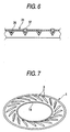
- the edge portion 1 provided around the outer circumference of the diaphragm main body to resiliently support the diaphragm main body on the frame has a plurality of groove ribs 3 integrally molded to enhance the reproducing capacity of low sound range, as shown in Fig. 7.
- This rib 3 is a groove having a V-character shape in transverse section, so-called a tangential edge, which extends in a tangential direction of the inner circumferential edge 1a (i.e., outer circumferential edge of the diaphragm main body) of the edge portion 1 and is disposed at an equal interval in a circumferential direction.
- This rib 3 increases the flexural rigidity in an extending direction of the groove (i.e., a tangential direction of the outer circumferential edge of the diaphragm main body), but serves to decrease the flexural rigidity due to an expansion or contraction of the groove width in a crossing direction of the groove (i.e., a radial direction of the diaphragm main body) . Consequently, the rib 3 makes the diaphragm easy to move and reduces the stiffness s 0 .
- an improved method of low sound range by forming the rib 3 had a drawback that since the rib 3 is intermittently disposed, the reinforcement or easiness of deformation of the rib 3 can not be attained uniformly over the entire area of the edge portion 1, and the edge portion 1 is fixed to the frame less uniformly over the entire circumference, whereby there is the possibility that the load on the edge portion 1 becomes maximum in a specific region due to a vibration propagation at the time of reproducing the sound. Due to the above reasons, when an input signal was large (large input), or the diaphragm was made thinner, there was the risk that the quality of reproduced sound was degraded due to the rolling of the edge portion or the local distortion. Also, there was the risk that the rolling might occur when the weight or compliance was unbalanced to lay a voice coil lead wire on the edge portion 1.
- the present invention has been achieved in the light of the above-mentioned problems, and it is an object of the invention to provide a speaker and a speaker diaphragm with the higher reproducing capacity of low sound range by forming a plurality of ribs in the edge portion to reduce the stiffness s 0 , in which the reproducing performance of low sound range is enhanced by supplementing a drawback that occurs by forming the rib to reduce the stiffness S 0 , and the occurrence of the rolling is suppressed, whereby the high quality reproduction of sound with less distortion is realized even at the time of large input.
- a speaker including a frame; a diaphragm main body supported resiliently on the frame via an edge portion around outer circumference thereof; a groove rib integrally molded in the edge portion; and a regulation member provided on a part of the front or back face of the edge portion, and adapted to partially improve a flexural strength of the edge portion.
- a speaker diaphragm including a diaphragm main body integrally formed with an edge portion around outer circumference thereof; a groove rib integrally formed in the edge portion; a regulation member provided on a part of the front or back face of the edge portion, and adapted to partially improve a flexural strength of the edge portion.
- the regulation member provided in the edge portion increases the effective mass of the vibration system, and decreases the low sound resonance frequency f 0 by increasing m 0 in the expression (1) for calculating the low sound resonance frequency f 0 . Accordingly, the lower stiffness s 0 of the support portion of the vibration system and the increased effective mass m 0 of the vibration system by disposing the ribs can cooperate to enhance the reproducing performance of low sound range, thereby easily enhancing the reproducing capacity of low sound range.
- the regulation member provided in the edge portion may be disposed between the ribs formed on the edge portion or on the rib, whereby it is possible to extend the reinforcing effect of the rib to a wider range, or to supplement the drawback that occurs when the stiffness s 0 is reduced, because the rib is reinforced over a local region having less flexural strength in the edge portion caused by an individual difference in assembling. Accordingly, the acceptable input is increased as compared with the conventional practice where the greater reproducing performance of low sound range relied only on reducing the stiffness s 0 , whereby the occurrence of the rolling is suppressed at the time of large input and the high quality reproduction with less distortion is realized.
- the regulation member may be formed by applying an adhesive or an agglutinant.
- the hardness or weight of the regulation member is easily balanced by adjusting the amount of the adhesive or the agglutinant applied. Also, there is no need for increasing the number of parts.
- a plurality of the regulation members made of different materials may be provided. Also, a plurality of the regulation members having different sizes may be provided. In this manner, even if there is a minute difference in the reproducing performance between individuals owing to an assembling error or a tolerance of components, it is possible to make the fine adjustments for the reproducing performance to eliminate a dispersion in the reproducing performance between the products caused by individual differences in assembling, thereby stably producing the speaker that can make the high quality reproduction.
- the regulation member may be provided within a grooved portion of the groove rib. In this manner, the positioning. operation in providing the regulation member is facilitated.
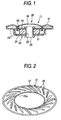
- Fig. 1 shows the speaker according to one embodiment of the invention.
- the speaker 11 of this embodiment is employed in an audio system for vehicle, in which a magnetic circuit 20 is composed of a magnet 21, a pole piece 22, a yoke frame 23, and a base plate 24, in which a bore 25 is provided concentrically in the central portion thereof, and the magnetic circuit 20 is integrated by caulking both ends of an eyelet 26 inserted through the bore 25.
- a diaphragm 29 is composed of a diaphragm main body 30 and a ring-like edge portion 31 leading to the outer circumference of the diaphragm main body 30. Because the outer circumferential edge of the edge portion 31 is joined with a rising portion around the outer circumference of the yoke frame 23, the diaphragm main body 30 is resiliently supported to be displaceable with respect to the yoke frame 23. Also, a voice coil 33 bonded on the backside of the diaphragm main body 30 is received movably in a magnetic gap between the yoke frame 23 and the magnet 21.
- the edge portion 31 has a plurality of groove-like ribs 35 integrally molded to enhance the reproducing capacity of low sound range, as shown in Fig. 2.
- the rib 35 is a groove having a V-character shape in transverse section, so-called a tangential edge, which extends in a tangential direction of the inner circumferential edge 31a (i.e., outer circumferential edge of the diaphragm main body 30) of the edge portion 31 and is disposed at an equal interval in a circumferential direction.
- This rib 35 increases the flexural rigidity in an extending direction of the groove (i.e., tangential direction of the outer circumferential edge of the diaphragm main body 30), but serves to decrease the flexural rigidity due to an expansion or contraction of the groove width in a crossing direction of the groove (i.e., radial direction of the diaphragm main body 30), so that the diaphragm main body is easily displaced to make the diaphragm easy to move and reduce the stiffness s 0 .
- a regulation member 37 of predetermined size for partially improving the flexural rigidity of the edge portion 31 is provided on a part of the surface of the edge portion 31.
- the regulation member 37 is formed by applying an adhesive or an agglutinant in the embodiment.
- the adhesive or the agglutinant used maybe preferably vinyl acetate, acrylic rubber or butyl rubber damping agent.
- the regulation member 37 is disposed on the rib 35 to cover the rib 35.
- the regulation member is disposed at an equal interval, but when the edge portion 31 has a remarkable dispersion in the vibration performance in the circumferential direction, the regulation member 37 may be disposed at an unequal interval in the circumferential direction in the sense of eliminating the dispersion and equalizing the vibration performance in the circumferential direction.
- the regulation members 37 made of different materials or having different sizes may be provided.
- the regulation member 37 provided in the edge portion 31 increases the effective mass of the vibration system, and decreases the low sound resonance frequency f 0 by increasing the effective mass m 0 of the vibration system in the previous expression (1) for calculating the low sound resonance frequency f 0 . Accordingly, the lower stiffness s 0 for the support portion of the vibration system and the increased effective mass m 0 of the vibration system can cooperate to enhance the reproducing performance of low sound range by disposing the ribs 35, thereby easily enhancing the reproducing capacity of low sound range.
- the regulation member 37 provided in the edge portion 31 may be disposed between the ribs 35 formed on the edge portion 31 or on the rib 35, whereby it is possible to extend the reinforcing effect of the rib to a wider range, or to supplement the drawback that occurs when the stiffness s 0 is reduced because the rib 35 is reinforced over a local region having less flexural strength in the edge portion 31 caused by an individual difference in assembling. Accordingly, the acceptable input is increased as compared with the conventional practice where the greater reproducing performance of low sound range relied only on reducing the stiffness s 0 , whereby the occurrence of the rolling is suppressed at the time of large input and the high quality reproduction with less distortion is realized.
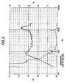
- Fig. 3 is a graph representing the frequency characteristics of an output sound pressure level (solid line) and the total harmonic distortion rate (broken line) in the conventional speaker.
- Fig. 4 is a graph representing the frequency characteristics of an output sound pressure level (solid line) and the total harmonic distortion rate (broken line) in the speaker according to the embodiment.
- Fig. 5 is a table listing the output sound pressure level and the total harmonic distortion rate in the conventional speaker and the speaker according to the embodiment. As will be clearly seen from Figs. 3 to 5, with the speaker of this embodiment, the distortion by rolling could be decreased from 8.15% to 4.94% (see THD2 in Fig. 5).
- the regulation member 37 is provided on the rib 35 to cover the rib 35, whereas it may be provided within a grooved portion of the rib 35, as shown in Fig. 6. In this manner, the positioning operation for the regulation member 37 can be facilitated.
- the regulation member 37 is provided on the surface of the edge portion 31, whereas the regulation member 37 may be provided on the back face of the edge portion 31.
- the regulation member provided in the edge portion increases the effective mass of the vibration system, and decreases the low sound resonance frequency f 0 by increasing the effective mass m 0 in the expression (1) for calculating the low sound resonance frequency f 0 . Accordingly, the lower stiffness s0 of the support portion of the vibration system and the increased effective mass m 0 of the vibration system by disposing the ribs can cooperate to enhance the reproducing performance of low sound range, thereby easily enhancing the reproducing capacity of low sound range.
- the regulation member provided in the edge portion may be disposed between the ribs formed on the edge portion or on the rib, whereby it is possible to extend the reinforcing effect of the rib to a wider range, or to supplement the drawback that occurs when the stiffness s 0 is reduced, because the rib is reinforced over a local region having less flexural strength in the edge portion caused by an individual difference in assembling. Accordingly, the acceptable input is increased as compared with the conventional practice where the greater reproducing performance of low sound range relied only on reducing the stiffness s 0 , whereby the occurrence of the rolling is suppressed at the time of large input and the high quality reproduction with less distortion is realized.
Landscapes
- Engineering & Computer Science (AREA)
- Multimedia (AREA)
- Physics & Mathematics (AREA)
- Acoustics & Sound (AREA)
- Signal Processing (AREA)
- Diaphragms For Electromechanical Transducers (AREA)
- Audible-Bandwidth Dynamoelectric Transducers Other Than Pickups (AREA)
Abstract
Description
Claims (12)
- A speaker comprising:a frame;a diaphragm main body supported resiliently on the frame via an edge portion around outer circumference thereof;a groove rib integrally molded in the edge portion; anda regulation member provided on a part of the front or back face of the edge portion, and adapted to partially improve a flexural strength of the edge portion.
- The speaker as claimed in claim 1, wherein the regulation member is formed by applying an adhesive.
- The speaker as claimed in claim 1, wherein the regulation member is formed by applying an agglutinant.
- The speaker as claimed in claim 1, wherein a plurality of the regulation members made of different materials are provided.
- The speaker as claimed in claim 1, wherein a plurality of the 'regulation members having different sizes are provided.
- The speaker as claimed in claim 1, wherein the regulation member is provided within a grooved portion of the groove rib.
- A speaker diaphragm comprising:a diaphragm main body integrally formed with an edge portion around outer circumference thereof;a groove rib integrally formed in the edge portion;a regulation member provided on a part of the front or back face of the edge portion, and adapted to partially improve a flexural strength of the edge portion.
- The speaker diaphragm as claimed in claim 7, wherein the regulation member is formed by applying an adhesive.
- The speaker diaphragm as claimed in claim 7, wherein the regulation member is formed by applying an agglutinant.
- The speaker diaphragm as claimed in claim 7, wherein a plurality of the regulation members made of different materials are provided.
- The speaker diaphragm as claimed in claim 7, wherein a plurality of the regulation members having different sizes are provided.
- The speaker diaphragm as claimed in claim 7, wherein the regulation member is provided within a grooved portion of the groove rib.
Applications Claiming Priority (2)
| Application Number | Priority Date | Filing Date | Title |
|---|---|---|---|
| JP2002204689A JP2004048494A (en) | 2002-07-12 | 2002-07-12 | Loudspeaker system and diaphragm for loudspeaker |
| JP2002204689 | 2002-07-12 |
Publications (2)
| Publication Number | Publication Date |
|---|---|
| EP1381251A2 true EP1381251A2 (en) | 2004-01-14 |
| EP1381251A3 EP1381251A3 (en) | 2005-07-13 |
Family
ID=29728542
Family Applications (1)
| Application Number | Title | Priority Date | Filing Date |
|---|---|---|---|
| EP03253944A Withdrawn EP1381251A3 (en) | 2002-07-12 | 2003-06-23 | Speaker and speaker diaphragm |
Country Status (3)
| Country | Link |
|---|---|
| US (1) | US6957714B2 (en) |
| EP (1) | EP1381251A3 (en) |
| JP (1) | JP2004048494A (en) |
Cited By (5)
| Publication number | Priority date | Publication date | Assignee | Title |
|---|---|---|---|---|
| EP1659823A3 (en) * | 2004-11-19 | 2006-08-02 | Bose Corporation | Loudspeaker suspension |
| WO2008150653A1 (en) * | 2007-05-31 | 2008-12-11 | Bose Corporation | Diaphragm surround |
| US8139812B2 (en) | 2004-11-19 | 2012-03-20 | Subarna Basnet | Loudspeaker suspension |
| US8397861B1 (en) | 2012-03-02 | 2013-03-19 | Bose Corporation | Diaphragm surround |
| CN105050005A (en) * | 2008-02-25 | 2015-11-11 | 日本先锋公司 | Loudspeaker device |
Families Citing this family (31)
| Publication number | Priority date | Publication date | Assignee | Title |
|---|---|---|---|---|
| WO2005107315A1 (en) * | 2004-04-29 | 2005-11-10 | Koninklijke Philips Electronics N.V. | Diaphragm for a loudspeaker with a moving coil |
| JP2008515325A (en) * | 2004-09-30 | 2008-05-08 | ピーエスエス・ベルギー・エヌブイ | Loudspeaker with acoustic member |
| JP2006166070A (en) * | 2004-12-08 | 2006-06-22 | Matsushita Electric Ind Co Ltd | Speaker |
| JP2006287418A (en) | 2005-03-31 | 2006-10-19 | Pioneer Electronic Corp | Speaker apparatus |
| CN1921704A (en) * | 2005-08-26 | 2007-02-28 | 富准精密工业(深圳)有限公司 | Sound membrane for minitype electroacoustic device |
| JP2007281986A (en) * | 2006-04-10 | 2007-10-25 | Minebea Co Ltd | Speaker and speaker diaphragm |
| US7931115B2 (en) * | 2007-05-31 | 2011-04-26 | Bose Corporation | Diaphragm surrounding |
| US7275620B1 (en) | 2007-07-19 | 2007-10-02 | Mitek Corp., Inc. | Square speaker |
| JP4743793B2 (en) * | 2007-08-29 | 2011-08-10 | オンキヨー株式会社 | Speaker diaphragm and speaker using the same |
| TWI386075B (en) * | 2008-01-22 | 2013-02-11 | S C Soong George | Eliminate the vibration of the diaphragm |
| WO2009107192A1 (en) | 2008-02-25 | 2009-09-03 | パイオニア株式会社 | Vibrator for acoustic converter, and speaker device |
| JP5665194B2 (en) * | 2011-08-19 | 2015-02-04 | 株式会社オーディオテクニカ | Electroacoustic transducer diaphragm and method of manufacturing the same |
| US8816178B2 (en) * | 2012-05-16 | 2014-08-26 | Philip S. GELB | System of removing overtones and rings in a drum set |
| US9253576B2 (en) | 2013-11-21 | 2016-02-02 | Bose Corporation | Suspension for acoustic device |
| EP3089478B1 (en) | 2013-12-27 | 2018-12-05 | Sony Corporation | Edge structure of diaphragm |
| CN104796824B (en) * | 2014-01-16 | 2018-03-13 | 宁波升亚电子有限公司 | A kind of outstanding side structure of loudspeaker vibration unit |
| CN204425608U (en) * | 2015-02-02 | 2015-06-24 | 瑞声光电科技(常州)有限公司 | Loudspeaker enclosure |
| GB2542382A (en) * | 2015-09-17 | 2017-03-22 | Gp Acoustics (Uk) Ltd | Low-profile loudspeaker |
| EP3166333A1 (en) * | 2015-11-03 | 2017-05-10 | Fibona Acoustics ApS | Loudspeaker membrane and low-profile loudspeaker |
| DK178943B1 (en) * | 2015-11-03 | 2017-06-19 | Fibona Acoustics Aps | Loudspeaker membrane and low-profile loudspeaker |
| CN206923035U (en) * | 2017-06-20 | 2018-01-23 | 瑞声科技(新加坡)有限公司 | Sound film, microphone device and electronic equipment |
| CN206923031U (en) * | 2017-06-20 | 2018-01-23 | 瑞声科技(新加坡)有限公司 | Sound film, microphone device and electronic equipment |
| CN207354581U (en) * | 2017-06-20 | 2018-05-11 | 瑞声科技(新加坡)有限公司 | Sound film, microphone device and electronic equipment |
| US11128956B2 (en) | 2017-07-27 | 2021-09-21 | Sony Corporation | Edge of diaphragm and speaker unit |
| JP2019161542A (en) * | 2018-03-15 | 2019-09-19 | オンキヨー株式会社 | Diaphragm, speaker unit including the same, headphone, earphone, and method of manufacturing diaphragm |
| CN208638609U (en) * | 2018-06-12 | 2019-03-22 | 瑞声科技(新加坡)有限公司 | Vibrating diaphragm and acoustical generator with the vibrating diaphragm |
| JP7323756B2 (en) * | 2018-10-09 | 2023-08-09 | オンキヨー株式会社 | Diaphragms and speaker units, headphones, and earphones using the same |
| US11297438B2 (en) * | 2018-10-19 | 2022-04-05 | Sound Solutions International Co., Ltd. | Electrodynamic acoustic transducer having a polygonal membrane with improved compliance |
| USD971176S1 (en) * | 2019-09-18 | 2022-11-29 | Sony Corporation | Acoustic transducer |
| US12294845B2 (en) * | 2022-07-01 | 2025-05-06 | Fortemedia, Inc. | Package structure of micro speaker |
| GB2626085B (en) * | 2022-12-30 | 2025-01-08 | Tymphany Hk Ltd | Vibration module, speaker having the same, and manufacturing method thereof |
Family Cites Families (24)
| Publication number | Priority date | Publication date | Assignee | Title |
|---|---|---|---|---|
| US1844487A (en) * | 1928-06-14 | 1932-02-09 | Rca Corp | Diaphragm |
| US1832608A (en) * | 1930-11-12 | 1931-11-17 | Alexander I Abrahams | Diaphragm for acoustic devices |
| US1990409A (en) * | 1932-02-19 | 1935-02-05 | Neville Athol Ernest | Acoustical diaphragm |
| US2302178A (en) * | 1940-11-12 | 1942-11-17 | Joseph B Brennan | Acoustic diaphragm |
| US2439665A (en) * | 1944-01-31 | 1948-04-13 | Rca Corp | Sound reproducing device |
| US2531634A (en) * | 1945-01-11 | 1950-11-28 | Athol E N Lawrance | Acoustical diaphragm with stiffening means |
| US2863520A (en) * | 1955-03-11 | 1958-12-09 | Gen Dynamics Corp | Loudspeaker cone rim treatment |
| US4324312A (en) * | 1978-11-14 | 1982-04-13 | James B. Lansing Sound, Inc. | Diaphragm suspension construction |
| US4581496A (en) * | 1979-09-04 | 1986-04-08 | Emhart Industries, Inc. | Diaphragm for attenuating harmonic response in an electroacoustic transducer |
| US4433214A (en) * | 1981-12-24 | 1984-02-21 | Motorola, Inc. | Acoustical transducer with a slotted piston suspension |
| JPS58199000A (en) * | 1982-05-17 | 1983-11-19 | Matsushita Electric Ind Co Ltd | electrodynamic speaker |
| JPS58221597A (en) * | 1982-06-17 | 1983-12-23 | Matsushita Electric Ind Co Ltd | electrodynamic speaker |
| JPS61276499A (en) * | 1985-05-31 | 1986-12-06 | Pioneer Electronic Corp | Diaphragm for loudspeaker |
| JPH02281899A (en) * | 1989-04-22 | 1990-11-19 | Pioneer Electron Corp | Cone type loudspeaker |
| JPH0723497A (en) * | 1993-06-30 | 1995-01-24 | Matsushita Electric Ind Co Ltd | Speaker diaphragm |
| US5647007A (en) * | 1994-12-22 | 1997-07-08 | Helen Of Troy Limited | Optimized sound components for hair dryer stereo system |
| US5590211A (en) * | 1995-07-14 | 1996-12-31 | Chang; Ching-Lu | Microphone |
| JPH09224297A (en) * | 1996-02-16 | 1997-08-26 | Sharp Corp | Acoustic transducer diaphragm |
| JPH11313391A (en) * | 1998-04-28 | 1999-11-09 | Foster Electric Co Ltd | Edge of diaphragm for speaker |
| US6611604B1 (en) * | 1999-10-22 | 2003-08-26 | Stillwater Designs & Audio, Inc. | Ultra low frequency transducer and loud speaker comprising same |
| JP4286408B2 (en) * | 1999-11-01 | 2009-07-01 | フォスター電機株式会社 | Electroacoustic transducer |
| US6700987B2 (en) * | 2000-08-25 | 2004-03-02 | Matsushita Electric Industrial Co., Ltd. | Loudspeaker |
| JP4513220B2 (en) * | 2001-03-08 | 2010-07-28 | ソニー株式会社 | Speaker device |
| CA2407123C (en) * | 2001-10-16 | 2007-12-18 | Audio Products International Corp. | Low distortion loudspeaker cone suspension |
-
2002
- 2002-07-12 JP JP2002204689A patent/JP2004048494A/en active Pending
-
2003
- 2003-06-23 EP EP03253944A patent/EP1381251A3/en not_active Withdrawn
- 2003-07-14 US US10/617,784 patent/US6957714B2/en not_active Expired - Fee Related
Cited By (7)
| Publication number | Priority date | Publication date | Assignee | Title |
|---|---|---|---|---|
| EP1659823A3 (en) * | 2004-11-19 | 2006-08-02 | Bose Corporation | Loudspeaker suspension |
| US7397927B2 (en) | 2004-11-19 | 2008-07-08 | Bose Corporation | Loudspeaker suspension |
| US8139812B2 (en) | 2004-11-19 | 2012-03-20 | Subarna Basnet | Loudspeaker suspension |
| WO2008150653A1 (en) * | 2007-05-31 | 2008-12-11 | Bose Corporation | Diaphragm surround |
| US7699139B2 (en) | 2007-05-31 | 2010-04-20 | Bose Corporation | Diaphragm surround |
| CN105050005A (en) * | 2008-02-25 | 2015-11-11 | 日本先锋公司 | Loudspeaker device |
| US8397861B1 (en) | 2012-03-02 | 2013-03-19 | Bose Corporation | Diaphragm surround |
Also Published As
| Publication number | Publication date |
|---|---|
| JP2004048494A (en) | 2004-02-12 |
| EP1381251A3 (en) | 2005-07-13 |
| US6957714B2 (en) | 2005-10-25 |
| US20040007420A1 (en) | 2004-01-15 |
Similar Documents
| Publication | Publication Date | Title |
|---|---|---|
| US6957714B2 (en) | Speaker and speaker diaphragm | |
| KR100905348B1 (en) | speaker | |
| US8041068B2 (en) | Loudspeaker | |
| JP4735299B2 (en) | Speaker | |
| US11770653B2 (en) | Speaker | |
| JP4735405B2 (en) | Speaker damper and speaker using the same | |
| JP2548580Y2 (en) | Dynamic microphone | |
| CN101213872A (en) | speaker | |
| US20090028377A1 (en) | Damper for speaker and speaker using the damper | |
| EP1833278A1 (en) | Speaker | |
| JP4626462B2 (en) | Speaker | |
| JP4618116B2 (en) | Speaker | |
| JP4560372B2 (en) | Speaker device | |
| US6804370B2 (en) | Speaker capable to playback in wide frequency range | |
| JP2009130666A (en) | Electroacoustic transducer | |
| JP4735406B2 (en) | Speaker | |
| US7706560B2 (en) | Speaker apparatus | |
| JP2002281587A (en) | Speaker | |
| US20240098424A1 (en) | Speaker | |
| KR102152980B1 (en) | The exciter for vibrating panel | |
| JPH08251691A (en) | Speaker unit | |
| JP4735275B2 (en) | Speaker | |
| JP2006129111A (en) | Loudspeaker and diaphragm therefor | |
| JPH08168094A (en) | Speaker | |
| JP2007088674A (en) | Speaker |
Legal Events
| Date | Code | Title | Description |
|---|---|---|---|
| PUAI | Public reference made under article 153(3) epc to a published international application that has entered the european phase |
Free format text: ORIGINAL CODE: 0009012 |
|
| AK | Designated contracting states |
Kind code of ref document: A2 Designated state(s): AT BE BG CH CY CZ DE DK EE ES FI FR GB GR HU IE IT LI LU MC NL PT RO SE SI SK TR |
|
| AX | Request for extension of the european patent |
Extension state: AL LT LV MK |
|
| PUAL | Search report despatched |
Free format text: ORIGINAL CODE: 0009013 |
|
| AK | Designated contracting states |
Kind code of ref document: A3 Designated state(s): AT BE BG CH CY CZ DE DK EE ES FI FR GB GR HU IE IT LI LU MC NL PT RO SE SI SK TR |
|
| AX | Request for extension of the european patent |
Extension state: AL LT LV MK |
|
| 17P | Request for examination filed |
Effective date: 20051223 |
|
| AKX | Designation fees paid |
Designated state(s): DE FR GB |
|
| RAP1 | Party data changed (applicant data changed or rights of an application transferred) |
Owner name: TOHOKU PIONEER CORPORATION Owner name: PIONEER CORPORATION |
|
| STAA | Information on the status of an ep patent application or granted ep patent |
Free format text: STATUS: THE APPLICATION IS DEEMED TO BE WITHDRAWN |
|
| 18D | Application deemed to be withdrawn |
Effective date: 20110104 |