US8041068B2 - Loudspeaker - Google Patents
Loudspeaker Download PDFInfo
- Publication number
- US8041068B2 US8041068B2 US11/916,480 US91648007A US8041068B2 US 8041068 B2 US8041068 B2 US 8041068B2 US 91648007 A US91648007 A US 91648007A US 8041068 B2 US8041068 B2 US 8041068B2
- Authority
- US
- United States
- Prior art keywords
- edge
- loudspeaker
- damper
- diaphragm
- young
- Prior art date
- Legal status (The legal status is an assumption and is not a legal conclusion. Google has not performed a legal analysis and makes no representation as to the accuracy of the status listed.)
- Active, expires
Links
- 239000000463 material Substances 0.000 claims description 9
- 229920001971 elastomer Polymers 0.000 claims description 8
- 239000006260 foam Substances 0.000 claims description 8
- 229920001821 foam rubber Polymers 0.000 claims description 8
- 229920002803 thermoplastic polyurethane Polymers 0.000 claims description 3
- 239000013585 weight reducing agent Substances 0.000 abstract 1
- 125000006850 spacer group Chemical group 0.000 description 13
- 229920005989 resin Polymers 0.000 description 7
- 239000011347 resin Substances 0.000 description 7
- JOYRKODLDBILNP-UHFFFAOYSA-N Ethyl urethane Chemical compound CCOC(N)=O JOYRKODLDBILNP-UHFFFAOYSA-N 0.000 description 6
- 239000004744 fabric Substances 0.000 description 6
- 229920003048 styrene butadiene rubber Polymers 0.000 description 6
- 239000000853 adhesive Substances 0.000 description 4
- 230000001070 adhesive effect Effects 0.000 description 4
- 230000001965 increasing effect Effects 0.000 description 3
- -1 acryl Chemical group 0.000 description 2
- 230000002708 enhancing effect Effects 0.000 description 2
- 239000012779 reinforcing material Substances 0.000 description 2
- 230000005236 sound signal Effects 0.000 description 2
- 239000012141 concentrate Substances 0.000 description 1
- 239000000428 dust Substances 0.000 description 1
- 230000000694 effects Effects 0.000 description 1
- 230000005489 elastic deformation Effects 0.000 description 1
- 238000005096 rolling process Methods 0.000 description 1
- 239000000725 suspension Substances 0.000 description 1
Images


Classifications
-
- H—ELECTRICITY
- H04—ELECTRIC COMMUNICATION TECHNIQUE
- H04R—LOUDSPEAKERS, MICROPHONES, GRAMOPHONE PICK-UPS OR LIKE ACOUSTIC ELECTROMECHANICAL TRANSDUCERS; DEAF-AID SETS; PUBLIC ADDRESS SYSTEMS
- H04R9/00—Transducers of moving-coil, moving-strip, or moving-wire type
- H04R9/02—Details
- H04R9/04—Construction, mounting, or centering of coil
- H04R9/041—Centering
- H04R9/043—Inner suspension or damper, e.g. spider
-
- H—ELECTRICITY
- H04—ELECTRIC COMMUNICATION TECHNIQUE
- H04R—LOUDSPEAKERS, MICROPHONES, GRAMOPHONE PICK-UPS OR LIKE ACOUSTIC ELECTROMECHANICAL TRANSDUCERS; DEAF-AID SETS; PUBLIC ADDRESS SYSTEMS
- H04R9/00—Transducers of moving-coil, moving-strip, or moving-wire type
- H04R9/06—Loudspeakers
-
- H—ELECTRICITY
- H04—ELECTRIC COMMUNICATION TECHNIQUE
- H04R—LOUDSPEAKERS, MICROPHONES, GRAMOPHONE PICK-UPS OR LIKE ACOUSTIC ELECTROMECHANICAL TRANSDUCERS; DEAF-AID SETS; PUBLIC ADDRESS SYSTEMS
- H04R2400/00—Loudspeakers
- H04R2400/07—Suspension between moving magnetic core and housing
-
- H—ELECTRICITY
- H04—ELECTRIC COMMUNICATION TECHNIQUE
- H04R—LOUDSPEAKERS, MICROPHONES, GRAMOPHONE PICK-UPS OR LIKE ACOUSTIC ELECTROMECHANICAL TRANSDUCERS; DEAF-AID SETS; PUBLIC ADDRESS SYSTEMS
- H04R7/00—Diaphragms for electromechanical transducers; Cones
- H04R7/16—Mounting or tensioning of diaphragms or cones
- H04R7/18—Mounting or tensioning of diaphragms or cones at the periphery
- H04R7/20—Securing diaphragm or cone resiliently to support by flexible material, springs, cords, or strands
Definitions
- the present invention relates to a loudspeaker for use on various electronic appliances.
- the conventional loudspeaker 100 has a magnetic circuit 101 , a voice coil 102 , a diaphragm 103 and a frame 105 , as shown in FIG. 12 .
- the voice coil 102 is arranged movable relative to the magnetic gap provided over the magnetic circuit 101 and connected to an inner rim of the diaphragm 103 .
- the diaphragm 103 has an outer rim connected to the frame 105 via a diaphragm edge 104 .
- diaphragm 103 has a rear surface connected to the frame 105 via a suspension holder 106 and an edge 107 .
- the vertical excursion of diaphragm 103 is given symmetric with respect to the vertical. This reduces distortion of loudspeaker 100 .
- Such a conventional loudspeaker 100 is disclosed in Japanese Patent Unexamined Publication No. 2004-7332 (patent document 1), for example.
- the present invention provides a loudspeaker which has a low distortion characteristic and a high driving efficiency.
- a loudspeaker in the invention has a frame, a magnetic circuit, a voice coil, a diaphragm, a first combination and a second combination.
- the magnetic circuit supported by the frame, is to form a magnetic gap.
- the voice coil is arranged movable relative to the magnetic gap.
- the diaphragm has an outer rim connected to the frame via a diaphragm edge and an inner rim connected to the voice coil.
- the first and second combinations are both provided closer to the magnetic circuit than the diaphragm, thus having an inner rim connected to the voice coil and an outer rim connected to the frame.
- the first combination has a first damper and a first edge while the second combination has a second damper and a second edge.
- the first edge has a first edge protrusion protruding in a direction toward the diaphragm or in a direction opposite to the diaphragm.
- the second edge has a second edge protrusion protruding in a direction opposite to the protruding direction of the first edge protrusion.
- FIG. 1 is a sectional view of a loudspeaker according to embodiment 1 of the present invention.
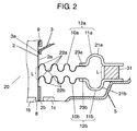
- FIG. 2 is an essential-part magnifying sectional view of the loudspeaker shown in FIG. 1 .
- FIG. 3 is an essential-part magnifying sectional view of a loudspeaker according to another example of embodiment 1 of the invention.
- FIG. 4 is a sectional view of a loudspeaker according to embodiment 2 of the invention.
- FIG. 5 is a sectional view of a loudspeaker according to another example of embodiment 2 of the invention.
- FIG. 6 is a sectional view of a loudspeaker according to still another example of embodiment 2 of the invention.
- FIG. 7 is a sectional view of a loudspeaker according to embodiment 3 of the invention.
- FIG. 8 is an essential-part magnifying sectional view of the loudspeaker shown in FIG. 7 .
- FIG. 9 is an essential-part magnifying sectional view of a loudspeaker according to another example of embodiment 31 of the invention.
- FIG. 10 is a sectional view of a loudspeaker according to embodiment 4 of the invention.
- FIG. 11 is an essential-part magnifying sectional view of the loudspeaker shown in FIG. 10 .
- FIG. 12 is a sectional view of a conventional loudspeaker.
- FIG. 1 is a sectional view showing loudspeaker 20 according to embodiment 1 of the invention.
- FIG. 2 is an essential-part magnifying sectional view of loudspeaker 20 shown in FIG. 1 .
- loudspeaker 20 has frame 5 in an inverted-cone form, magnetic circuit 1 , voice coil 2 and diaphragm 3 .
- Magnetic circuit 1 is arranged at a bottom center of frame 5 .
- magnetic circuit 1 is formed by combining and bonding together disk-like magnet 1 a , disk-like plate 1 b and cylindrical yoke 1 c .
- Magnetic gap 8 is formed between the inner rim surface of a sidewall of yoke 1 c and the outer rim surface of plate 1 b .
- Magnetic gap 8 has a cylindrical form opening to the above.
- Voice coil 2 has cylindrical body 2 a and coil 2 b wound around the outer rim of body 2 a .
- Voice coil 2 is connected, at its upper outer rim, with diaphragm 3 in a thin-dish form.
- Voice coil 2 is arranged movable vertically relative to magnetic gap 8 .
- dust cap 9 is provided for dustproof, at the upper end of voice coil 2 .
- Diaphragm 3 is a sound generation source of loudspeaker 20 .
- diaphragm 3 utilizes, as its main material, a pulp or a resin compatible with high hardness and internal loss.
- Diaphragm 3 has an outer rim connected to the opening end of frame 5 via diaphragm edge 4 (hereinafter, referred to as edge 4 ) protruding to the above.
- diaphragm 3 has an inner rim bonded and fixed to the outer rim of body 2 a .
- Edge 4 is formed by use of a material of urethane foam resin, foam rubber, SBR rubber or cloth, in order not to apply a movable load to diaphragm 3 .
- First damper 10 a (hereinafter, referred to as damper 10 a ) and second damper 10 b (hereinafter, referred to as damper 10 b ) are connected to an outer rim side of body 2 a , as shown in FIGS. 1 and 2 .
- Dampers 10 a , 10 b are connected to body 2 a , in respective positions closer to magnetic circuit 1 than fixing region 3 a of diaphragm 3 .
- Damper 10 a and damper 10 b are connected to body 2 a , with predetermined spacing L.
- Damper 10 a has an outer rim connected to frame 5 via first edge 11 a (hereinafter, referred to as edge 11 a ) separate from the damper 10 a .
- damper 10 b has an outer rim connected to frame 5 via second edge 11 b (hereinafter, referred to as edge 11 b ) separate from the damper 10 b .
- Damper 10 a and edge 11 a constitute first combination 12 a (hereinafter, referred to as combination 12 a ).
- damper 10 b and edge 11 b constitute second combination 12 b (hereinafter, referred to as combination 12 b ).
- Edge 11 a and edge 11 b are fixed on the frame 5 , in a state integrated together via spacer 31 .
- Spacer 31 has a height dimension L so that edge 11 a and edge 11 b can be fixed on frame 5 with predetermined distance L of spacing.
- the spacing between dampers 10 a and 10 b and the spacing between edges 11 a and 11 b are both structured with the predetermined distance L of spacing.
- the spacing between dampers 10 a and 10 b and the spacing between edges 11 a and 11 b are not necessarily limited to the equal spacing. Those may be determined by taking account of the forms of dampers 10 a , 10 b , edges 11 a , 11 b , spacer 31 and so on.
- Dampers 10 a , 10 b are of a corrugated ring-like structure. This provides a structure allowing for being flexible correspondingly to a vertical excursion of voice coil 2 . Dampers 10 a , 10 b are formed using a material of urethane foam resin, foam rubber, SBR rubber or cloth, in order not to apply a large movable load to diaphragm 3 , similarly to edge 4 .
- Edge 11 a has first edge protrusion 21 a (hereinafter, referred to as protrusion 21 a ) semicircular in section that protrudes toward diaphragm 3 .
- edge 11 b has second edge protrusion 21 b (hereinafter, referred to as protrusion 21 b ) semicircular in section that protrudes oppositely to diaphragm 3 .
- Edges 11 a , 11 b are formed using a material of urethane foam resin, foam rubber, SBR rubber or cloth, in order not to apply a large movable load to diaphragm 3 .
- Young's modulus E 0 of edge 4 Comparing between Young's modulus E 0 of edge 4 , Young's modulus E 1 of edge 11 a and Young's modulus E 2 of edge 11 b , it is preferred that Young's modulus E 0 of edge 4 is the smallest, Young's modulus E 1 of edge 11 a is the next smallest and Young's modulus E 2 of edge 11 b is the greatest. Namely, it is preferred that the relationship E 0 ⁇ E 1 ⁇ E 2 is satisfied wherein edge 4 is the softest, next, edge 11 a is softer and edge 11 b is the hardest. The reason of this will be detailed later.
- edges 4 , 11 a , 11 b by forming edges 4 , 11 a , 11 b by using urethane resin, foam urethane resin or foam rubber and edge 11 b by using rubber material, the condition E 0 ⁇ E 1 ⁇ E 2 is to be obtained.
- Loudspeaker 20 when inputted an audio signal to coil 2 b , reacts with the magnetic field formed in magnetic gap 8 so that voice coil 2 operates in the vertical direction. By the operation of the voice coil 2 , diaphragm 3 is vibrated to generate sound from loudspeaker 20 . Particularly, by the provision of edges 11 a , 11 b at outer rims of dampers 10 a , 10 b , the sound generated by loudspeaker 20 is suppressed from distorting, further enhancing the driving efficiency of loudspeaker 20 .
- dampers 10 a , 10 b are connected to voice coil 2 and frame 5 , thus having the purpose of suppressing the rolling occurring upon operation of voice coil 2 .
- dampers 10 a , 10 b having a corrugated ring-like structure is given with elasticity in order to easily follow up the operation of voice coil 2 .
- the dampers 10 a , 10 b having the corrugated ring-like structure the operation of voice coil 2 less undergoes a significant load at a small excursion of voice coil 2 .
- the load of dampers 10 a , 10 b increases on the operation of voice coil 2 .
- combination 12 a has damper 10 a and edge 11 a while combination 12 b has damper 10 b and edge 11 b .
- damper 10 a at its outer rim is connected to frame 5 via edge 11 a .
- damper 10 b at its outer rim is connected to frame 5 via edge 11 b .
- This increases the excursion of voice coil 2 , to apply a stress to edges 11 a , 11 b when damper 10 a , 10 b exerts load to voice coil 2 or so. For this reason, protrusion 21 a of edge 11 a elastically deforms in accordance with the stress applied to edge 11 a .
- protrusion 21 b of edge 11 b elastically deforms in accordance with the stress applied to edge 11 b .
- edges 11 a , 11 b are smooth in its elastic deformation to smoothly absorb the stress applied to edges 11 a , 11 b .
- loudspeaker 20 shown in FIGS. 1 and 2 has protrusions 21 a , 21 b that are semicircular in sectional form.
- the sectional form of protrusion 21 a , 21 b is not limited to semicircular form.
- edge 11 a , 11 b to concentrate at protrusion 21 a , 21 b and smoothly elastically deform edge 11 a , 11 b , acute-angled protrusion in section or elliptic protrusion (not shown), for example, is applicable.
- voice coil 2 is vertically held by three supports of edge 4 , combination 12 a and combination 12 b .
- edge 4 greatest in plane shape is thin-walled to reduce the weight of the excursion part including diaphragm 3 , edge 4 and the like. This reduces the weight of diaphragm 3 and the weight of edge 4 , to enhance the driving efficiency of loudspeaker 20 .
- edge 4 is thin-walled, the support strength of voice coil 2 lowers. For this reason, edge 11 a and edge 11 b are structured thick-walled rather than edge 4 . This compensates for the lowering the support strength of voice coil 2 .
- Young's modulus Ea of combination 12 a and Young's modulus Eb of combination 12 b are greater than Young's modulus E 0 of edge 4 .
- the relationship E 0 ⁇ Ea and E 0 ⁇ Eb is satisfied, wherein combinations 12 a , 12 b are harder than edge 4 .
- loudspeaker 20 thus structured, supporting voice coil 2 is dominated by the support of combinations 12 a , 12 b . Accordingly, diaphragm 3 is effectively suppressed from distorting in its vertical excursion by placing the vertical load on combination 12 a and the vertical load on combination 12 b in an equal state to a possible extent.
- dampers 10 a , 10 b are of a corrugated ring-like structure, each of which has a plurality of third protrusions 22 a protruding toward diaphragm 3 and fourth protrusions 22 b protruding oppositely to third protrusions 22 a . Accordingly, dampers 10 a , 10 b basically have substantially equal vertical loads.
- edge 11 b has protrusion 21 b protruding to the below. Namely, protrusion 21 b is in a form protruding opposite to diaphragm 3 . Furthermore, protrusion 21 b has substantially a semicircular form in section. This allows edge 11 b to readily deform to the below in FIG. 2 , i.e. in a direction opposite to diaphragm 3 . Conversely, edge 11 b is not ready to deform in a direction to the above in FIG. 2 , i.e. toward diaphragm 3 .
- edge 11 a is provided in order to absorb the difference of vertical deformability of edge 11 b .
- the provision of edge 11 a serves to absorb the characteristic ready to deform to the below, the difference in vertical load on edge 11 b . For this reason, edge 11 a has a form opposed to edge 11 b.
- edge 11 a has protrusion 21 a that protrudes in a direction to the above in FIG. 2 , i.e. toward diaphragm 3 .
- protrusion 21 a has substantially a semicircular form in section. This makes it easy to deform in the direction to the above in FIG. 2 , i.e. toward diaphragm 3 . Conversely, deformation is not easy in a direction to the below in FIG. 2 , i.e. opposite to diaphragm 3 .
- protrusions 21 a of edge 11 a and protrusion 21 b of edge 11 b are oppositely arranged to each other with a substantial semicircular form in section. Due to this, the vertical load on edge 11 a and vertical load on edge 11 b are given substantially equal in the state of magnitude.
- edges 11 a , 11 b Young's modulus E 1 of edge 11 a is somewhat smaller than Young's modulus E 2 of edge 11 b .
- edge 4 is in a form protruding to the above in FIG. 1 , as shown in FIG. 1 . Consequently, taking account of the load difference at edge 4 , edge 11 a is less hard as compared to edge 11 b.
- edge 4 is light in weight by virtue of its small thickness. This reduces the weight of diaphragm 3 and the weight of edge 4 , to raise the driving efficiency of loudspeaker 20 . Consequently, load is not so great in vertical excursion of diaphragm 3 .
- edge 4 protrudes to the above in FIG. 1 , edge 4 is ready to deform to the above and conversely not easy to deform to the below. This difference, although somewhat in degree, turns into a difference of vertical excursion load as to diaphragm 3 .
- loudspeaker 20 of the invention has Young's modulus E 1 at edge 11 a somewhat smaller than Young's modulus E 2 at edge 11 b , as noted before. Namely, edge 11 a is less hard as compared to edge 11 b . This adjusts the difference of vertical excursion load of diaphragm 3 into a substantially equal state.
- voice coil 2 is easier to move to the above in FIG. 1 and the upper in FIG. 2 as compared to the excursion to the below because of the reason resulting from the forms of edge 4 and edge 11 a .
- the reason resulting from the form of edge 11 b downward excursion is easier as compared to upward excursion. From this fact, the easiness of excursion is taken into account on the assumption that edge 11 a and edge 4 are in a pair for one edge 11 b .
- Young's modulus E 1 of edge 11 a is somewhat smaller than Young's modulus E 2 of edge 11 b .
- the vertical excursion of diaphragm 3 is given substantially symmetric with respect to the vertical, thus reducing distortions in loudspeaker 20 .
- edge 4 greatest in plane shape is weight-reduced, the excursion part of loudspeaker 20 can be easily reduced in weight.
- loudspeaker 20 having high driving efficiency is obtainable for loudspeaker 20 for reproducing middle and higher ranges of sound.
- the power linearity due to dampers 10 a , 10 b is ensured linear before the excursion of voice coil 2 increases to a certain extent.
- linearity is complemented for by the elasticity of edges 11 a , 11 b .
- the total Young's modulus of edges 11 a , 11 b are desirably greater than the total Young's modulus of dampers 10 a , 10 b .
- edges 11 a , 11 b are desirably harder than dampers 10 a , 10 b.
- damper 10 a and edge 11 a are desirably set with different Young's moduli from each other so that the both can function independently in accordance with the excursion of voice coil 2 .
- the Young's modulus of between damper 10 a and edge 11 a i.e. at connection 23 a of damper 10 a and edge 11 a , greater than the Young's modulus of damper 10 a and greater than the Young's modulus of edge 11 a , independence of damper 10 a and edge 11 a is ensured for damper 10 a and edge 11 a .
- connection 23 a is desirably harder than damper 10 a and than edge 11 a.
- damper 10 b and edge 11 b are desirably set with different Young's moduli from each other so that the both can function independently in accordance with the excursion of voice coil 2 .
- the Young's modulus of between damper 10 b and edge 11 b i.e. at connection 23 b of damper 10 b and edge 11 b , greater than the Young's modulus of damper 10 b and greater than the Young's modulus of edge 11 b
- connection 23 b is desirably harder than damper 10 b and than edge 11 b.
- connection 23 a In order to establish the Young's modulus of connection 23 a greater than the Young's modulus of damper 10 a and than the Young's modulus of edge 11 a , it is preferable to use a hard adhesive, say, based on acryl as an adhesive type for bonding between edge 11 a and damper 10 a . If reinforcing material (not shown) is pasted on connection 23 a , the Young's modulus of connection 23 a can be easily increased.
- connection 23 b in order to establish the Young's modulus of connection 23 b greater than the Young's modulus of damper 10 b and than the Young's modulus of edge 11 b , it is preferable to use a hard adhesive, say, based on acryl as an adhesive type for bonding between edge 11 b and damper 10 b . If reinforcing material (not shown) is pasted on connection 23 b , the Young's modulus of connection 23 a can be easily increased.
- FIG. 3 is an essential-part magnifying sectional view showing another example of loudspeaker 20 according to embodiment 1 of the invention.
- Loudspeaker 20 shown in FIG. 3 is different in edge 11 a , 11 b structure, i.e. combination 12 a , 12 b structure, from loudspeaker 20 shown in FIGS. 1 and 2 , wherein the other elements are same in structure.
- loudspeaker 20 shown in FIG. 3 has a structure that protrusion 21 a of edge 11 a protrudes in a direction opposite to diaphragm 3 while protrusion 21 b of edge 11 b protrudes in a direction toward diaphragm 3 .
- Damper 10 a and edge 11 a constitute first combination 12 a while damper 10 b and edge 11 b constitute second combination 12 b .
- Edge 11 a and edge 11 b are fixed on frame 5 , in a state integrated via spacer 31 .
- loudspeaker 20 With loudspeaker shown in FIG. 3 , loudspeaker 20 is provided that the sound generated by loudspeaker 20 is suppressed against distortions wherein driving efficiency of loudspeaker 20 is enhanced. Besides, loudspeaker 20 having high driving efficiency is obtainable for loudspeaker 20 for reproducing middle and higher ranges of sound because of loudspeaker 20 excursion part is easily weight-reduced.
- Embodiment 2 of the invention is explained below by using figures. Note that similar reference character is attached to the similar structure to embodiment 1, to omit the detailed explanation thereof.
- FIG. 4 is a sectional view showing loudspeaker 20 according to embodiment 2 of the invention.
- FIG. 5 is a sectional view showing another example of loudspeaker 20 according to embodiment 2 of the invention.
- FIG. 6 is a sectional view showing another example of loudspeaker 20 according to embodiment 2 of the invention.
- Loudspeaker 20 of embodiment 2 is different from loudspeaker 20 of embodiment 1 in respect of edge 11 a , 11 b structure, i.e. combination 12 a , 12 b structure, wherein the other elements are same in structure as embodiment 1.
- loudspeaker 20 shown in FIG. 4 is provided with first edge 11 c (hereinafter, referred to as edge 11 c ) in place of edge 11 a of loudspeaker 20 of embodiment 1.
- Edge 11 c has two first edge protrusions 21 c (hereinafter, referred to as protrusions 21 c ) and one third edge protrusion 21 e (hereinafter, referred to as protrusion 21 e ), thereby having a corrugated sectional form.
- Protrusion 21 c protrudes in a direction toward diaphragm 3 while protrusion 21 e protrudes in a direction opposite to diaphragm 3 .
- Edge 11 c is formed by use of a material of urethane foam resin, foam rubber, SBR rubber or cloth, in order not to apply a large movable load to diaphragm 3 .
- Damper 10 a and edge 11 c constitute first combination 12 c .
- Edge 11 c and edge 11 b are fixed on frame 5 , in a state integrated together via spacer 31 .
- edge 11 c has two protrusions 21 c protruding toward above in FIG. 4 , i.e. in a direction toward diaphragm 3 , and one protrusion 21 e protruding in a direction opposite to diaphragm 3 . Due to this, deformation readily occurs in the direction toward above in FIG. 4 , i.e. toward diaphragm 3 . Conversely, deformation does not readily occur in the direction toward below in FIG. 4 , i.e. opposite to diaphragm 3 . Consequently, by combining edge 11 b and edge 11 c in a manner as shown in FIG. 4 , the magnitude of a vertical load on edge 11 b and the magnitude of a vertical load on edge 11 c are given substantially equal in state.
- Young's modulus E 1 of edge 11 c is somewhat smaller as compared to Young's modulus E 2 of edge 11 b .
- edge 11 c is somewhat less hard as compared to edge 11 b .
- the reason Young's modulus E 1 of edge 11 c is somewhat smaller as compared to Young's modulus E 2 of edge 11 b is similar to the reason Young's modulus E 1 of edge 11 a is somewhat smaller as compared to Young's modulus E 2 of edge 11 b as was explained in embodiment 1. Accordingly, explanation in detail is omitted.
- loudspeaker 20 shown in FIG. 4 the vertical excursion of diaphragm 3 is given substantially symmetric with respect to the vertical, which reduces distortion of loudspeaker 20 . Furthermore, because edge 4 greatest in plane shape is thin-walled and weight-reduced, the excursion part of loudspeaker 20 is easily weight-reduced. Thus, loudspeaker 20 having high driving efficiency is obtainable for loudspeaker 20 for reproducing middle and higher ranges of sound.
- Loudspeaker 20 shown in FIG. 5 is provided with second edge 11 d (hereinafter, referred to as edge 11 d ) in place of edge 11 b of loudspeaker 20 of embodiment 1.
- Edge 11 d has two second edge protrusions 21 d (hereinafter, referred to as protrusions 21 d ) and one fourth edge protrusion 21 f (hereinafter referred to as protrusion 21 f ), thereby having a corrugated sectional form.
- Protrusion 21 f protrudes in a direction toward diaphragm 3 while protrusion 21 d protrudes in a direction opposite to diaphragm 3 .
- Edge 11 d is formed by use of a material of urethane foam resin, foam rubber, SBR rubber or cloth, in order not to apply a large movable load to diaphragm 3 .
- Damper 10 b and edge 11 d constitute second combination 12 d .
- Edge 11 a and edge 11 d are fixed on the frame 5 , in a state integrated together via spacer 31 .
- edge 11 d has one protrusion 21 f protruding toward above in FIG. 5 , i.e. in a direction toward diaphragm 3 , and two protrusions 21 d protruding below in FIG. 5 , i.e. in a direction opposite to diaphragm 3 . Due to this, deformation readily occurs in the direction toward below in FIG. 5 , i.e. opposite to diaphragm 3 . Conversely, deformation does not readily occur in the direction toward above in FIG. 5 , i.e. toward diaphragm 3 . Consequently, by combining edge 11 a and edge 11 d in a manner as shown in FIG. 5 , the magnitude of a vertical load on edge 11 a and the magnitude of a vertical load on edge 11 d are given substantially equal in state.
- Young's modulus E 1 of edge 11 a is somewhat smaller as compared to Young's modulus E 2 of edge 11 d .
- edge 11 a is somewhat less hard as compared to edge 11 d .
- the reason Young's modulus E 1 of edge 11 a is somewhat smaller as compared to Young's modulus E 2 of edge 11 d is similar to the reason Young's modulus E 1 of edge 11 a is somewhat smaller as compared to Young's modulus E 2 of edge 11 b as was explained in embodiment 1. Accordingly, explanation in detail is omitted.
- loudspeaker 20 shown in FIG. 5 the vertical excursion of diaphragm 3 is given substantially symmetric with respect to the vertical, which reduces distortions in loudspeaker 20 . Furthermore, because edge 4 greatest in plane shape is thin-walled and weight-reduced, the excursion part of loudspeaker 20 is easily weight-reduced. Thus, loudspeaker 20 having high driving efficiency is obtainable for loudspeaker 20 for reproducing middle and higher ranges of sound.
- Loudspeaker 20 shown in FIG. 6 is provided with edges 11 c , 11 d in place of edges 11 a , 11 b of loudspeaker 20 of embodiment 1.
- Damper 10 a and edge 11 c constitute first combination 12 c .
- damper 10 b and edge 11 d constitute second combination 12 d .
- Edge 11 c and edge 11 d are fixed on frame 5 , in a state integrated together via spacer 31 .
- edge 11 d has one protrusion 21 f protruding in a direction toward diaphragm 3 and two protrusions 21 d protruding in a direction opposite to diaphragm 3 . Due to this, deformation readily occurs in the direction opposite to diaphragm 3 , and conversely deformation does not readily occur in the direction toward diaphragm 3 . Meanwhile, edge 11 c has two protrusions 21 c protruding in a direction toward diaphragm 3 and one protrusion 21 e protruding in a direction opposite to diaphragm 3 .
- edge 11 c and edge 11 d As shown in FIG. 6 , the magnitude of vertical load on edge 11 c and the magnitude of vertical load on edge 11 d are given substantially equal in state.
- Young's modulus E 1 of edge 11 c is somewhat smaller as compared to Young's modulus E 2 of edge 11 d . Namely, edge 11 c is somewhat less hard as compared to edge 11 d .
- the reason Young's modulus E 1 of edge 11 c is somewhat smaller as compared to Young's modulus E 2 of edge 11 d is similar to the reason Young's modulus E 1 of edge 11 a is somewhat smaller as compared to Young's modulus E 2 of edge 11 b as was explained in embodiment 1. Accordingly, explanation in detail is omitted.
- loudspeaker 20 shown in FIG. 6 the vertical excursion of diaphragm 3 is given substantially symmetric with respect to the vertical, which reduces distortion of loudspeaker 20 . Furthermore, because edge 4 greatest in plane shape is thin-walled and weight-reduced, the excursion part of loudspeaker 20 is easily weight-reduced. Thus, loudspeaker 20 having high driving efficiency is obtainable for loudspeaker 20 for reproducing middle and higher ranges of sound.
- Embodiment 3 of the invention is explained below by use of figures. Note that similar reference character is attached to the similar structure to embodiment 1 or 2, to omit the detailed explanation thereof.
- FIG. 7 is a sectional view showing loudspeaker 20 according to embodiment 3 of the invention.
- FIG. 8 is an essential-part magnifying view of loudspeaker 20 shown in FIG. 7 .
- Loudspeaker 20 of embodiment 3 is different from loudspeaker 20 of embodiment 1 or 2 in respect of first combination 12 a structure and second combination 12 b structure, wherein the other elements are same in structure as embodiment 1 or 2.
- damper 10 a and damper 10 b at their outer rims are fixed on frame 5 , in a state integrated together via spacer 31 , as shown in FIGS. 7 and 8 .
- Spacer 31 has a height dimension L so that dampers 10 a , 10 b are fixed on frame 5 with predetermined distance L.
- damper 10 a has an inner rim connected to an outer rim of main body 2 a of voice coil 2 via edge 11 a separate from damper 10 a .
- damper 10 b has an inner rim connected to an outer rim of main body 2 a of voice coil 2 via edge 11 b separate from damper 10 b .
- Edges 11 a , 11 b are connected on main body 2 a in a position closer to the magnetic circuit 1 than fixing region 3 a of diaphragm 3 . Edge 11 a and Edge 11 b are connected on main body 2 a , with predetermined distance L of spacing. Damper 10 a and edge 11 a constitutes first combination 12 a . Likewise, damper 10 b and edge 11 b constitutes second combination 12 b .
- the spacing between dampers 10 a and 10 b and the spacing between edges 11 a and 11 b are both structured with predetermined distance L of spacing. However, the spacing between dampers 10 a and 10 b and the spacing between edges 11 a and 11 b are not necessarily limited to the spacing equality. Those may be determined by taking account of the forms of dampers 10 a , 10 b , edges 11 a , 11 b , spacer 31 and so on.
- loudspeaker 20 of embodiment 3 when an audio signal is inputted to coil 2 b , voice coil 2 operates vertically in response to a magnetic field formed in the magnetic gap 8 similarly to loudspeaker 20 of embodiment 1 or 2.
- diaphragm 3 is vibrated to generate sound from loudspeaker 20 .
- edges 11 a , 11 b at inner rims of dampers 10 a , 10 b the sound generated by loudspeaker 20 is suppressed from distorting, further enhancing the driving efficiency of loudspeaker 20 .
- the excursion part of loudspeaker 20 is easily reduced in weight.
- loudspeaker 20 having high driving efficiency is obtainable for loudspeaker 20 for reproducing middle and higher ranges of sound.
- FIG. 9 is an essential-part magnifying sectional view showing another embodiment of loudspeaker 20 according to embodiment 3 of the invention.
- Loudspeaker 20 shown in FIG. 9 is different in edge 11 a , 11 b structure, i.e. combination 12 a , 12 b structure, from loudspeaker 20 shown in FIGS. 7 and 8 , wherein the other elements are same in structure.
- edge 11 a has protrusion 21 a that protrudes in a direction opposite to diaphragm 3 while edge 11 b has protrusion 21 b that protrudes in a direction toward diaphragm 3 .
- Damper 10 a and edge 11 a constitutes first combination 12 a while damper 10 b and edge 11 b constitutes second combination 12 b .
- Damper 10 a and damper 10 b are fixed on the frame 5 , in a state integrated together via spacer 31 .
- loudspeaker 20 With loudspeaker shown in FIG. 9 , loudspeaker 20 is provided that the sound generated by loudspeaker 20 is suppressed against distortions further with driving efficiency of loudspeaker 20 enhanced. Likewise, loudspeaker 20 with high driving efficiency is obtainable for loudspeaker 20 for reproducing middle and higher ranges of sound because of loudspeaker 20 excursion part is easily weight-reduced.
- Embodiment 4 of the invention is explained below by use of figures. Note that similar reference character is attached to the similar structure to embodiment 1, 2 or 3, to omit the detailed explanation thereof.
- FIG. 10 is a sectional view showing loudspeaker 20 according to embodiment 4 of the invention.
- FIG. 11 is an essential-part magnifying view of loudspeaker 20 shown in FIG. 10 .
- Loudspeaker 20 of embodiment 4 is different from loudspeaker 20 of embodiment 1, 2 or 3 in respect of first combination 12 a structure and second combination 12 b structure, wherein the other elements are same in structure as embodiment 1.
- third damper 10 c (hereinafter, referred to as damper 10 c ) is inserted between the outer rim of edge 11 a and frame 5 of loudspeaker 20 according to embodiment 1.
- fourth damper 10 d (hereinafter, referred to as damper 10 c ) is inserted between the outer rim of edge 11 b and frame 5 .
- Damper 10 a , edge 11 a and damper 10 c constitute first combination 12 a .
- damper 10 b , edge 11 b and damper 10 d constitute second combination 12 b .
- Damper 10 a and damper 10 b are fixed on frame 5 , in a state integrated together via spacer 31 .
- dampers 10 c , 10 d are of a corrugated ring-like structure similarly to dampers 10 a , 10 b .
- This provides a structure allowing for being flexible correspondingly to a vertical excursion of voice coil 2 .
- Dampers 10 c , 10 d are formed using a material of urethane foam resin, foam rubber, SBR rubber or cloth, in order not to apply a large movable load to diaphragm 3 , similarly to dampers 10 a , 10 b .
- Dampers 10 c , 10 d are each structured having, in plurality, third protrusion protruding 22 a in a direction toward diaphragm 3 and fourth protrusion 22 b protruding in a direction opposite to third protrusion 22 a . Accordingly, basically, vertical load is substantially equal at dampers 10 c , 10 d . Due to this, loudspeaker 20 is identical in basic operation, function and effect to the foregoing embodiments 1, 2 and 3.
- loudspeaker 20 shown by embodiment 4 the vertical excursion of diaphragm 3 is substantially symmetric with respect to the vertical, thus reducing distortion at loudspeaker 20 . Furthermore, edge 4 greatest in plane shape is thin-walled and weight-reduced thus reducing the weight of the excursion part of loudspeaker 20 .
- loudspeaker 20 having high driving efficiency is obtainable for loudspeaker 20 for reproducing middle and higher ranges of sound.
- Distortion of the loudspeaker in the invention is reduced in the sound generated by the loudspeaker and improved in driving efficiency. This results in usefulness particularly for loudspeakers for middle and higher range applications.
Landscapes
- Engineering & Computer Science (AREA)
- Physics & Mathematics (AREA)
- Acoustics & Sound (AREA)
- Signal Processing (AREA)
- Multimedia (AREA)
- Audible-Bandwidth Dynamoelectric Transducers Other Than Pickups (AREA)
- Diaphragms For Electromechanical Transducers (AREA)
Abstract
Description
- Patent Document 1: Japanese Patent Unexamined Publication No. 2004-7332
-
- 1. Magnetic circuit
- 2. Voice coil
- 3. Diaphragm
- 4. Diaphragm edge
- 5. Frame
- 8. Magnetic gap
- 10 a. First damper
- 10 b. Second damper
- 10 c. Third damper
- 10 d. Fourth damper
- 11 a, 11 c. First edge
- 11 b, 11 d. Second edge
- 12 a, 12 c. First combination
- 12 b, 12 d. Second combination
- 20. Loudspeaker
- 21 a, 21 c. First edge protrusion
- 21 b, 21 d. Second edge protrusion
- 21 e. Third edge protrusion
- 21 f. Fourth edge protrusion
- 22 a. Third protrusion
- 22 b. Fourth protrusion
- 23 a, 23 b. Connection
- 31. Spacer
Claims (6)
Applications Claiming Priority (5)
| Application Number | Priority Date | Filing Date | Title |
|---|---|---|---|
| JP2006-131333 | 2006-05-10 | ||
| JP2006131333A JP2007306203A (en) | 2006-05-10 | 2006-05-10 | Speaker |
| JP2006-131332 | 2006-05-10 | ||
| JP2006131332A JP4735406B2 (en) | 2006-05-10 | 2006-05-10 | Speaker |
| PCT/JP2007/059450 WO2007129685A1 (en) | 2006-05-10 | 2007-05-07 | Speaker |
Publications (2)
| Publication Number | Publication Date |
|---|---|
| US20090116680A1 US20090116680A1 (en) | 2009-05-07 |
| US8041068B2 true US8041068B2 (en) | 2011-10-18 |
Family
ID=38667794
Family Applications (1)
| Application Number | Title | Priority Date | Filing Date |
|---|---|---|---|
| US11/916,480 Active 2029-12-26 US8041068B2 (en) | 2006-05-10 | 2007-05-07 | Loudspeaker |
Country Status (4)
| Country | Link |
|---|---|
| US (1) | US8041068B2 (en) |
| EP (1) | EP1881734B1 (en) |
| KR (1) | KR20080014879A (en) |
| WO (1) | WO2007129685A1 (en) |
Cited By (3)
| Publication number | Priority date | Publication date | Assignee | Title |
|---|---|---|---|---|
| US20090028377A1 (en) * | 2006-04-04 | 2009-01-29 | Kimihiro Ando | Damper for speaker and speaker using the damper |
| US20140247960A1 (en) * | 2011-12-20 | 2014-09-04 | Aac Acoustic Technologies (Shenzhen) Co., Ltd. | Electromagnetic transducer |
| US9485586B2 (en) | 2013-03-15 | 2016-11-01 | Jeffery K Permanian | Speaker driver |
Families Citing this family (9)
| Publication number | Priority date | Publication date | Assignee | Title |
|---|---|---|---|---|
| US8169947B2 (en) | 2007-12-05 | 2012-05-01 | Qualcomm Incorporated | Method and apparatus for data-centric multiplexing |
| JPWO2009101813A1 (en) | 2008-02-14 | 2011-06-09 | パナソニック株式会社 | Speaker and electronic device |
| CN101277551B (en) * | 2008-05-05 | 2011-09-14 | 无锡杰夫电声有限公司 | Orientation sheet-supporting structure of thin type speaker |
| TWI538530B (en) * | 2011-12-13 | 2016-06-11 | Speaker | |
| US9066179B2 (en) * | 2013-09-09 | 2015-06-23 | Sonos, Inc. | Loudspeaker assembly configuration |
| CN105764013A (en) * | 2016-04-13 | 2016-07-13 | 巴士在线股份有限公司 | Loudspeaker structure formed by injection moulding of metal damper and support, and production process thereof |
| KR102499257B1 (en) * | 2017-10-20 | 2023-02-14 | 삼성전자주식회사 | Speaker |
| CN208369831U (en) * | 2018-05-04 | 2019-01-11 | 惠州超声音响有限公司 | A kind of loudspeaker of symmetrical double folding ring |
| CN108966095A (en) * | 2018-08-07 | 2018-12-07 | 张永春 | Loudspeaker unit and speaker unit |
Citations (16)
| Publication number | Priority date | Publication date | Assignee | Title |
|---|---|---|---|---|
| JPS5649188Y2 (en) | 1973-06-14 | 1981-11-17 | ||
| JPS5737582Y2 (en) | 1978-09-29 | 1982-08-18 | ||
| JPS5866797U (en) | 1981-10-27 | 1983-05-06 | パイオニア株式会社 | Damper support device for speakers |
| JPS62109596A (en) | 1985-11-07 | 1987-05-20 | 松下電器産業株式会社 | Centrifugal dehydrating washing machine |
| JPH02133097A (en) | 1988-11-14 | 1990-05-22 | Toshiba Corp | Controller for synchronous motor |
| JPH02133097U (en) | 1989-04-07 | 1990-11-05 | ||
| JPH03247099A (en) | 1990-02-23 | 1991-11-05 | Sharp Corp | Speaker |
| JPH09284890A (en) | 1996-04-15 | 1997-10-31 | Sony Corp | Speaker equipment |
| US5847333A (en) | 1996-05-31 | 1998-12-08 | U.S. Philips Corporation | Electrodynamic loudspeaker and system comprising the loudspeaker |
| WO1999004597A2 (en) | 1997-07-18 | 1999-01-28 | Mackie Designs Inc. | Pistonic motion, large excursion passive radiator |
| JP2003199192A (en) | 2001-10-16 | 2003-07-11 | Matsushita Electric Ind Co Ltd | Loudspeaker damper and loudspeaker |
| US20030185415A1 (en) * | 2001-06-11 | 2003-10-02 | Osamu Funahashi | Speaker |
| US6655495B2 (en) | 2001-10-16 | 2003-12-02 | Matsushita Electric Industrial Co., Ltd. | Loudspeaker damper and loudspeaker |
| JP2004007332A (en) | 2002-04-15 | 2004-01-08 | Matsushita Electric Ind Co Ltd | Speaker |
| US20050201588A1 (en) * | 2003-03-31 | 2005-09-15 | Osamu Funahashi | Speaker |
| JP4533465B2 (en) | 2007-06-01 | 2010-09-01 | 成幸 五十嵐 | Air-conditioning planting pot |
-
2007
- 2007-05-07 KR KR1020077029765A patent/KR20080014879A/en not_active Application Discontinuation
- 2007-05-07 US US11/916,480 patent/US8041068B2/en active Active
- 2007-05-07 EP EP07742885A patent/EP1881734B1/en not_active Expired - Fee Related
- 2007-05-07 WO PCT/JP2007/059450 patent/WO2007129685A1/en active Application Filing
Patent Citations (17)
| Publication number | Priority date | Publication date | Assignee | Title |
|---|---|---|---|---|
| JPS5649188Y2 (en) | 1973-06-14 | 1981-11-17 | ||
| JPS5737582Y2 (en) | 1978-09-29 | 1982-08-18 | ||
| JPS5866797U (en) | 1981-10-27 | 1983-05-06 | パイオニア株式会社 | Damper support device for speakers |
| JPS62109596A (en) | 1985-11-07 | 1987-05-20 | 松下電器産業株式会社 | Centrifugal dehydrating washing machine |
| JPH02133097A (en) | 1988-11-14 | 1990-05-22 | Toshiba Corp | Controller for synchronous motor |
| JPH02133097U (en) | 1989-04-07 | 1990-11-05 | ||
| JPH03247099A (en) | 1990-02-23 | 1991-11-05 | Sharp Corp | Speaker |
| JPH09284890A (en) | 1996-04-15 | 1997-10-31 | Sony Corp | Speaker equipment |
| US5847333A (en) | 1996-05-31 | 1998-12-08 | U.S. Philips Corporation | Electrodynamic loudspeaker and system comprising the loudspeaker |
| JPH11510033A (en) | 1996-05-31 | 1999-08-31 | フィリップス エレクトロニクス ネムローゼ フェンノートシャップ | Dynamic speaker and system including the speaker |
| WO1999004597A2 (en) | 1997-07-18 | 1999-01-28 | Mackie Designs Inc. | Pistonic motion, large excursion passive radiator |
| US20030185415A1 (en) * | 2001-06-11 | 2003-10-02 | Osamu Funahashi | Speaker |
| JP2003199192A (en) | 2001-10-16 | 2003-07-11 | Matsushita Electric Ind Co Ltd | Loudspeaker damper and loudspeaker |
| US6655495B2 (en) | 2001-10-16 | 2003-12-02 | Matsushita Electric Industrial Co., Ltd. | Loudspeaker damper and loudspeaker |
| JP2004007332A (en) | 2002-04-15 | 2004-01-08 | Matsushita Electric Ind Co Ltd | Speaker |
| US20050201588A1 (en) * | 2003-03-31 | 2005-09-15 | Osamu Funahashi | Speaker |
| JP4533465B2 (en) | 2007-06-01 | 2010-09-01 | 成幸 五十嵐 | Air-conditioning planting pot |
Non-Patent Citations (3)
| Title |
|---|
| International Search Report Dated Jun. 5, 2007. |
| Japanese Office action dated Jul. 13, 2010 for Appl. No. 2006-131332. |
| Supplementary European Search Report dated Jun. 23, 2010. |
Cited By (5)
| Publication number | Priority date | Publication date | Assignee | Title |
|---|---|---|---|---|
| US20090028377A1 (en) * | 2006-04-04 | 2009-01-29 | Kimihiro Ando | Damper for speaker and speaker using the damper |
| US8428298B2 (en) * | 2006-04-04 | 2013-04-23 | Panasonic Corporation | Damper for speaker and speaker using the damper |
| US20140247960A1 (en) * | 2011-12-20 | 2014-09-04 | Aac Acoustic Technologies (Shenzhen) Co., Ltd. | Electromagnetic transducer |
| US9426578B2 (en) * | 2011-12-20 | 2016-08-23 | Aac Acoustic Technologies (Shenzhen) Co., Ltd. | Electromagnetic transducer |
| US9485586B2 (en) | 2013-03-15 | 2016-11-01 | Jeffery K Permanian | Speaker driver |
Also Published As
| Publication number | Publication date |
|---|---|
| EP1881734B1 (en) | 2012-04-11 |
| US20090116680A1 (en) | 2009-05-07 |
| EP1881734A1 (en) | 2008-01-23 |
| WO2007129685A1 (en) | 2007-11-15 |
| EP1881734A4 (en) | 2010-07-21 |
| KR20080014879A (en) | 2008-02-14 |
Similar Documents
| Publication | Publication Date | Title |
|---|---|---|
| US8041068B2 (en) | Loudspeaker | |
| US7974434B2 (en) | Loudspeaker | |
| US8355523B2 (en) | Speaker | |
| JP4569476B2 (en) | Speaker | |
| US7532736B2 (en) | Speaker | |
| JP4735405B2 (en) | Speaker damper and speaker using the same | |
| JP2004304512A (en) | Speaker | |
| US7929724B2 (en) | Loudspeaker | |
| JP4735306B2 (en) | Speaker | |
| US8094862B2 (en) | Speaker | |
| US8005253B2 (en) | Speaker | |
| JP4735406B2 (en) | Speaker | |
| JP4784504B2 (en) | Speaker | |
| JP4735275B2 (en) | Speaker | |
| WO2009147700A1 (en) | Speaker | |
| JP2007306203A (en) | Speaker | |
| JP2007194702A (en) | Speaker | |
| JP2007306204A (en) | Speaker | |
| JP2007194700A (en) | Speaker |
Legal Events
| Date | Code | Title | Description |
|---|---|---|---|
| AS | Assignment |
Owner name: MATSUSHITA ELECTRIC INDUSTRIAL CO., LTD., JAPAN Free format text: ASSIGNMENT OF ASSIGNORS INTEREST;ASSIGNOR:FUNAHASHI, OSAMU;REEL/FRAME:020699/0800 Effective date: 20071011 |
|
| AS | Assignment |
Owner name: PANASONIC CORPORATION, JAPAN Free format text: CHANGE OF NAME;ASSIGNOR:MATSUSHITA ELECTRIC INDUSTRIAL CO., LTD.;REEL/FRAME:021818/0725 Effective date: 20081001 Owner name: PANASONIC CORPORATION,JAPAN Free format text: CHANGE OF NAME;ASSIGNOR:MATSUSHITA ELECTRIC INDUSTRIAL CO., LTD.;REEL/FRAME:021818/0725 Effective date: 20081001 |
|
| STCF | Information on status: patent grant |
Free format text: PATENTED CASE |
|
| FEPP | Fee payment procedure |
Free format text: PAYOR NUMBER ASSIGNED (ORIGINAL EVENT CODE: ASPN); ENTITY STATUS OF PATENT OWNER: LARGE ENTITY |
|
| FPAY | Fee payment |
Year of fee payment: 4 |
|
| MAFP | Maintenance fee payment |
Free format text: PAYMENT OF MAINTENANCE FEE, 8TH YEAR, LARGE ENTITY (ORIGINAL EVENT CODE: M1552); ENTITY STATUS OF PATENT OWNER: LARGE ENTITY Year of fee payment: 8 |
|
| MAFP | Maintenance fee payment |
Free format text: PAYMENT OF MAINTENANCE FEE, 12TH YEAR, LARGE ENTITY (ORIGINAL EVENT CODE: M1553); ENTITY STATUS OF PATENT OWNER: LARGE ENTITY Year of fee payment: 12 |
|
| AS | Assignment |
Owner name: PANASONIC HOLDINGS CORPORATION, JAPAN Free format text: CHANGE OF NAME;ASSIGNOR:PANASONIC CORPORATION;REEL/FRAME:066644/0558 Effective date: 20220401 |
|
| AS | Assignment |
Owner name: PANASONIC AUTOMOTIVE SYSTEMS CO., LTD., JAPAN Free format text: ASSIGNMENT OF ASSIGNORS INTEREST;ASSIGNOR:PANASONIC HOLDINGS CORPORATION;REEL/FRAME:066957/0984 Effective date: 20240228 |