JP2009130666A - Electroacoustic transducer - Google Patents
Electroacoustic transducer Download PDFInfo
- Publication number
- JP2009130666A JP2009130666A JP2007304093A JP2007304093A JP2009130666A JP 2009130666 A JP2009130666 A JP 2009130666A JP 2007304093 A JP2007304093 A JP 2007304093A JP 2007304093 A JP2007304093 A JP 2007304093A JP 2009130666 A JP2009130666 A JP 2009130666A
- Authority
- JP
- Japan
- Prior art keywords
- voice coil
- electroacoustic transducer
- diaphragm
- magnetic circuit
- long
- Prior art date
- Legal status (The legal status is an assumption and is not a legal conclusion. Google has not performed a legal analysis and makes no representation as to the accuracy of the status listed.)
- Pending
Links
Images


Abstract
Description
本発明は電気音響変換器に係り、特にボイスコイル形状として長辺と短辺とを有する細長形状のボイスコイルを備えた導電型の電気音響変換器に関する。 The present invention relates to an electroacoustic transducer, and more particularly to a conductive electroacoustic transducer including an elongated voice coil having a long side and a short side as a voice coil shape.
近年、携帯電話機等の小型携帯機器においてオーディオ機能が重視されており、電気音響変換器としても、単なるコール音のみを目的とした圧電タイプから音響特性を重視した動電型の電気音響変換器が搭載されるようになってきた。しかもこれらの小型携帯機器は表示装置やキーボードにスペースをとられるため、電気音響変換器を取り付けるためのスペースがますます狭くなってきて従来の円形形状の電気音響変換器が取り付けられなくなっている。この対策として携帯電話機において大型化された表示装置を避けて細長形状の電気音響変換器を取り付けた構成がある。(例えば、特許文献1参照。)。 In recent years, audio functions have been emphasized in small portable devices such as mobile phones. As electroacoustic transducers, electrodynamic electroacoustic transducers that emphasize acoustic characteristics from piezoelectric types that are intended only for call sounds are also available. It has come to be installed. Moreover, since these small portable devices take up space in the display device and the keyboard, the space for mounting the electroacoustic transducer is becoming narrower and the conventional circular electroacoustic transducer cannot be mounted. As a countermeasure, there is a configuration in which an elongated electroacoustic transducer is attached to avoid an enlarged display device in a mobile phone. (For example, refer to Patent Document 1).
以下、図12、図13を用いて特許文献1に開示された従来技術における電気音響変換器を説明する。図12は特許文献1に開示された従来技術における電気音響変換器を備えた携帯電話機の正面図であり、図13は図12の電気音響変換器を構成するボイスコイルの斜視図である。図12において100は携帯電話機であり、表示装置111、マイク112、電気音響変換器である導電型スピーカ60を有する蓋部110と、キーボード121、機能ボタン122を有する本体部120とがヒンジ部130によって開閉可能に結合されている。
Hereinafter, the electroacoustic transducer in the prior art disclosed by
そして蓋部110においては、出来るだけ広い表示画面が望まれている表示装置111が大部分の面積を占有し、表示装置111とヒンジ部130との狭い隙間部分に細長形状の導電型スピーカ60が配置されている。図13は導電型スピーカ60を構成するボイスコイル64であり、ボイスコイル64の形状は導電型スピーカ60の細長形状に合わせて長方形になっている。すなわち、ボイスコイル64の長辺部64aの長さL1は短辺部64bの長さL2の2倍以上の細長形状となっている。 In the lid 110, the display device 111 for which a display screen that is as wide as possible occupies most of the area, and the elongated conductive speaker 60 is disposed in a narrow gap between the display device 111 and the hinge unit 130. Has been placed. FIG. 13 shows a voice coil 64 constituting the conductive speaker 60, and the shape of the voice coil 64 is rectangular according to the elongated shape of the conductive speaker 60. That is, the length L1 of the long side portion 64a of the voice coil 64 is an elongated shape that is twice or more the length L2 of the short side portion 64b.
しかしながら通常は、導電型スピーカのボイスコイルは円形形状をしているのが一般的である。そして導電型スピーカの駆動時にこのバランスのとれた円形形状によってボイスコイルの各部にかかる応力が均一になり、正常な音響出力を発生する事が出来るようになっていた。 However, normally, the voice coil of the conductive speaker is generally circular. When the conductive speaker is driven, the balanced circular shape makes the stress applied to each part of the voice coil uniform, and a normal sound output can be generated.
しかるに引用文献1における導電型スピーカ60のボイスコイル64は、長辺部64aの長さL1と短辺部64bの長さL2との比が2倍以上の細長形状となっているために、導電型スピーカの駆動時にこのアンバランスな形状によってボイスコイルの各部にかかる応力が不均一になり正常な音響出力を発生する事が出来ないという問題がある。すなわちボイスコイル64の長辺部64aの強度不足により、中域の周波数帯域にて、分割振動による異常音の発生、歪率の悪化等の不具合が発生する結果となる。
However, the voice coil 64 of the conductive speaker 60 in the cited
(発明の目的)
本発明は上記問題に鑑みなされたもので、携帯機器等の狭いスペースに配設が可能な細長形状を有しながら、中域の周波数帯域での分割振動による異常音の発生や、歪率悪化等の不具合の発生を改良した電気音響変換器を提供することを目的とする。
(Object of invention)
The present invention has been made in view of the above problems, and has an elongated shape that can be disposed in a narrow space such as a portable device, while generating abnormal noise due to divided vibration in a middle frequency band, and deterioration of distortion rate. An object of the present invention is to provide an electroacoustic transducer in which occurrence of defects such as the above is improved.
上記目的を達成するための本発明の電気音響変換器は、永久磁石、該永久磁石の一方の磁極側に固定したヨーク、他方の磁極側に固定したトッププレートよりなる磁気回路と、ボイスコイルを備えた振動膜とを有する導電型の電気音響変換器において、前記振動膜とボイスコイルは長辺と短辺とを有する細長形状に形成されるとともに、前記磁気回路を構成する磁気空隙も長辺と短辺とを有する細長形状に形成されてなり、前記振動膜の短辺方向に段差部を形成し、該段差部の側壁にボイスコイルの側面をガイドして補強したことを特徴とする。 In order to achieve the above object, an electroacoustic transducer of the present invention comprises a permanent magnet, a yoke fixed to one magnetic pole side of the permanent magnet, a magnetic circuit comprising a top plate fixed to the other magnetic pole side, and a voice coil. In the electroacoustic transducer of the conductive type having the vibration film provided, the vibration film and the voice coil are formed in an elongated shape having a long side and a short side, and a magnetic gap constituting the magnetic circuit is also a long side A step portion is formed in the short side direction of the vibration film, and a side surface of the voice coil is guided and reinforced on the side wall of the step portion.
前記段差部は振動膜の単辺方向の両端部に、少なくとも2個が設けられていることを特徴とする。 The step portion is characterized in that at least two step portions are provided at both end portions in the single side direction of the vibration film.
上記構成により、ボイスコイルの長辺側の強度不足を補強することで、中域の周波数帯域での分割振動による異常音の発生や、歪率悪化の発生を抑止することができ、音響特性の改善ができた。 With the above configuration, by reinforcing the shortage of strength on the long side of the voice coil, it is possible to suppress the occurrence of abnormal sounds due to divided vibrations in the middle frequency band and the deterioration of distortion, and the acoustic characteristics Improved.
前記段差部は振動膜の単辺を横切る凹形状溝によって形成され、前記凹形状溝の両端の側壁にボイスコイルの側面をガイドして補強していることを特徴とする。 The step portion is formed by a concave groove that crosses a single side of the diaphragm, and the side surfaces of the voice coil are guided and reinforced on the side walls at both ends of the concave groove.
前記段差部が複数個設けられていることを特徴とする。 A plurality of the step portions are provided.
前記段差部に対応するトッププレートの位置に、前記段差部を避けるための切欠部を設けたことを特徴とする。 A notch for avoiding the step is provided at the position of the top plate corresponding to the step.
上記ごとく磁気回路を構成するトッププレートの、振動膜段差部に対応する位置に、電気音響変換器の駆動時に振動する振動膜段差部を収納する切欠部を設けることによって電気音響変換器の高さを増すことなく、十分な音響特性の改善ができた。 As described above, the height of the electroacoustic transducer is provided by providing a notch for housing the vibrating membrane step portion that vibrates when the electroacoustic transducer is driven at a position corresponding to the vibrating membrane step portion of the top plate constituting the magnetic circuit. The acoustic characteristics can be improved sufficiently without increasing the frequency.
以上のように本発明の電気音響変換によれば、ボイスコイルの長辺側の強度不足を補強することで、中域の周波数帯域での分割振動による異常音の発生や、歪率悪化の発生を抑止することができ、音響特性の改善ができた。 As described above, according to the electroacoustic conversion of the present invention, by reinforcing the shortage of strength on the long side of the voice coil, abnormal sound is generated due to divided vibration in the middle frequency band, and distortion is deteriorated. Can be suppressed, and the acoustic characteristics can be improved.
以下本発明の実施形態における電気音響変換器を図面により詳細に説明する。図1から図9は本発明の第1実施形態における電気音響変換器の構成を示すものであり、図1は電気音響変換器の上面図、図2は図1の電気音響変換器のA−A断面図、図3は図1の電気音響変換器のB−B断面図、図4は本発明の第1実施形態における振動膜の上面図、図5は図4の拡大したC−C断面図、図6は図3のG部の拡大断面図、図7は図1の電気音響変換器から振動膜を取り外した磁気回路の上面図、図8は図7の磁気回路のA−A断面図、図9は図7の磁気回路のB−B断面図である。 Hereinafter, an electroacoustic transducer according to an embodiment of the present invention will be described in detail with reference to the drawings. 1 to 9 show the configuration of the electroacoustic transducer according to the first embodiment of the present invention. FIG. 1 is a top view of the electroacoustic transducer, and FIG. 2 is an A- of the electroacoustic transducer of FIG. A sectional view, FIG. 3 is a BB sectional view of the electroacoustic transducer of FIG. 1, FIG. 4 is a top view of the vibrating membrane in the first embodiment of the present invention, and FIG. 5 is an enlarged CC section of FIG. FIG. 6, FIG. 6 is an enlarged sectional view of a portion G in FIG. 3, FIG. 7 is a top view of the magnetic circuit with the vibrating membrane removed from the electroacoustic transducer in FIG. 1, and FIG. 9 and 9 are cross-sectional views of the magnetic circuit shown in FIG.
図1、図2、図3において10は電気音響変換器である導電型スピーカであり、従来の導電型スピーカ60と同様に細長形状となっている。1は永久磁石、2は永久磁石1の一方の磁極側に固定したヨーク、3は永久磁石1の他方の磁極側に固定したトッププレートであり、前記永久磁石1、ヨーク2、トッププレート3により磁気回路を構成している。4はボイスコイル、5はボイスコイル4を備えた振動膜、6は振動膜の単辺を横切るように形成された凹形状溝であり詳細については後述する。7はフレームであり、このフレーム7はヨーク2と結合されることにより磁気回路全体を支持している。8はプロテクタであり、前記フレーム7と結合してその間に振動膜5を挟持するとともに、振動膜5の上面側を保護する機能を有する。そして前記導電型スピーカ10の動作は基本的に従来の導電型スピーカの動作と同じであり、ヨーク2とトッププレート3によって形成される磁気空隙9内に配置されたボイスコイル4に通電することにより、振動膜5が振動して音響出力を発生する。
1, 2, and 3,
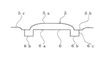
次に本発明の特徴である、振動膜5の凹形状溝6について説明する。図4、図5に示す如く振動膜5は、中央に湾曲した振動部5aと、コイルを接着するための平坦なコイル接着部5bと、プロテクタ8と前記フレーム7に挟持される支持部5cとが振動膜5の中心からリング状に連続して形成されている。そして振動膜5は長円形を有し、長辺部の長さL1と短辺部の長さL2との比が2倍以上の細長形状となっている。
Next, the
そして振動膜5の単辺を横切るように凹形状溝6が形成されており、この凹形状溝6は振動膜5の振動部5aから1段沈んだ第1溝6aと、第1溝6aの両端にさらに1段沈んだ第2溝6bが設けられ、この第2溝6bの両端が段差部6cとなってボイスコイル4の補強を行う部分である。そして凹形状溝6の長さはボイスコイル4の横幅と等しくなっている。
A
次に図6により振動膜5に対するボイスコイル4の取り付け及び補強構成について説明する。図6は図3におけるG部の拡大断面図であり、振動膜5に対するボイスコイル4の取り付け及び補強構成を示している。図6は図3で説明した如く、ヨーク2とトッププレート3によって形成される磁気空隙9内に振動膜5に固着されたボイスコイル4が配置された状態を示している。そして振動膜5に対するボイスコイル4の取り付け構成は、長円形状を有するボイスコイル4の上辺は全周に渡って振動膜5の平坦なコイル接着部5bに接着固定されており、またボイスコイル4の内周の一部が、振動膜5に設けられた凹形状溝6の段差部6cに側面をガイドされて補強されている。なお、段差部6cに対するボイスコイル4のガイドは圧接でも良いし、接着しても良い。
Next, the attachment and reinforcement structure of the
すなわち、振動膜5に対するボイスコイル4の取り付け構成は、解り易くするためにハッチングで示したコイル接着部5bに接着固定され、さらに内周の一部が段差部6cに側面をガイドされて補強されている。なお、このボイスコイル4を段差部6cでガイドする位置は、ボイスコイル4の長辺部の中央部付近に設けるのが、ボイスコイル4の長辺部の強度不足を補う上で最適である。
That is, the mounting structure of the
次に導電型スピーカ10の磁気回路の構成について説明する。
図7は図1の導電型スピーカ10から振動膜5を取り外した磁気回路の上面図、図8は図7の磁気回路のA−A断面図、図9は図7の磁気回路のB−B断面図であり、図1から図3に示す導電型スピーカ10と同一の各要素については番号のみを付し、重複する説明を省略する。
Next, the configuration of the magnetic circuit of the
7 is a top view of the magnetic circuit with the
すなわち本発明の磁気回路の特徴は図7及び図9に示す如く、前記振動膜5に形成された凹形状溝6の第2溝6bに対応するトッププレート3の位置に、前記段差部6cを避けるための切欠部3a、3bを設けたことであり、この切欠部3a、3bの位置には永久磁石1が見えている。そして図6に示す如くこの切欠部3a、3bによって振動膜5に形成された凹形状溝6の第2溝6bが振動する間隙Hが確保されている。
That is, as shown in FIGS. 7 and 9, the magnetic circuit of the present invention is characterized in that the step portion 6c is provided at the position of the
図10、図11は本発明の第2実施形態における電気音響変換器である導電型スピーカの構成を示すものであり、図10は導電型スピーカの上面図、図11は図10の導電型スピーカのA−A断面図である。また図10、図11の導電スピーカ20は図1、図2に示す第1実施形態における導電スピーカ10と基本的構成は同じであり、同一要素には同一番号を付し、重複する説明を省略する。
10 and 11 show the configuration of a conductive speaker that is an electroacoustic transducer according to the second embodiment of the present invention, FIG. 10 is a top view of the conductive speaker, and FIG. 11 is the conductive speaker of FIG. It is AA sectional drawing. The
導電型スピーカ20が導電型スピーカ10と異なるところは、振動膜5に形成された凹形状溝6が2個形成されることによって、複数の段差部が設けられていることである。すなわち、導電型スピーカ10においては、1個の凹形状溝6をボイスコイル4の長辺部の中央部に設けていたのに対し、導電型スピーカ20においては2個の凹形状溝6をボイスコイル4の長辺部の中央部から等間隔の位置に設けていることであり、この結果ボイスコイル4の側面をガイド段差部の数が倍になって、ボイスコイル4の長辺部の補強効果を高めている。
The difference between the
上記の如く本発明の電気音響変換器は、細長いボイスコイルの短辺側を振動膜に形成した段差部でガイドすることによって長辺側の強度不足を補強しているため、中域の周波数帯域での分割振動による異常音の発生や、歪率悪化の発生を抑止することができ、音響特性の改善ができるものである。 As described above, the electroacoustic transducer of the present invention reinforces the shortage of strength on the long side by guiding the short side of the elongated voice coil with the step portion formed on the vibration film, so that the frequency band in the middle range It is possible to suppress the generation of abnormal sounds due to the divided vibration and the deterioration of the distortion rate, thereby improving the acoustic characteristics.
1 永久磁石
2 ヨーク
3 トッププレート
3a、3b 切欠部
4 ボイスコイル
5 振動膜
6 凹形状溝
6a 第1溝
6b 第2溝
6c 段差部
7 フレーム
8 プロテクタ
10,20 導電型スピーカ
DESCRIPTION OF
Claims (5)
The electroacoustic transducer according to any one of claims 1 to 3, wherein a notch for avoiding the step is provided at a position of the top plate corresponding to the step.
Priority Applications (1)
| Application Number | Priority Date | Filing Date | Title |
|---|---|---|---|
| JP2007304093A JP2009130666A (en) | 2007-11-26 | 2007-11-26 | Electroacoustic transducer |
Applications Claiming Priority (1)
| Application Number | Priority Date | Filing Date | Title |
|---|---|---|---|
| JP2007304093A JP2009130666A (en) | 2007-11-26 | 2007-11-26 | Electroacoustic transducer |
Publications (1)
| Publication Number | Publication Date |
|---|---|
| JP2009130666A true JP2009130666A (en) | 2009-06-11 |
Family
ID=40821142
Family Applications (1)
| Application Number | Title | Priority Date | Filing Date |
|---|---|---|---|
| JP2007304093A Pending JP2009130666A (en) | 2007-11-26 | 2007-11-26 | Electroacoustic transducer |
Country Status (1)
| Country | Link |
|---|---|
| JP (1) | JP2009130666A (en) |
Cited By (2)
| Publication number | Priority date | Publication date | Assignee | Title |
|---|---|---|---|---|
| TWI504286B (en) * | 2011-08-19 | 2015-10-11 | Goertek Inc | Moving-coil type electro-acoustic conversing device |
| WO2017106985A1 (en) * | 2015-12-21 | 2017-06-29 | 邓克忠 | Pneumatic high pitch monomer having improved sound membrane and improved structure |
-
2007
- 2007-11-26 JP JP2007304093A patent/JP2009130666A/en active Pending
Cited By (3)
| Publication number | Priority date | Publication date | Assignee | Title |
|---|---|---|---|---|
| TWI504286B (en) * | 2011-08-19 | 2015-10-11 | Goertek Inc | Moving-coil type electro-acoustic conversing device |
| WO2017106985A1 (en) * | 2015-12-21 | 2017-06-29 | 邓克忠 | Pneumatic high pitch monomer having improved sound membrane and improved structure |
| US10623848B2 (en) | 2015-12-21 | 2020-04-14 | Ko-Chung Teng | Pneumatic tweeter unit having improved sound diaphragm and structure |
Similar Documents
| Publication | Publication Date | Title |
|---|---|---|
| US8989412B2 (en) | Piezoelectric acoustic transducer | |
| WO2013114872A1 (en) | Speaker, inner ear headphone provided with speaker, and hearing aid | |
| US10932050B2 (en) | Micro-speaker | |
| JP2007208877A (en) | Loudspeaker | |
| WO2005086530A1 (en) | Speaker | |
| US20080063234A1 (en) | Electroacoustic transducer | |
| CN107409259B (en) | Electronic sound equipment changing device | |
| US11770653B2 (en) | Speaker | |
| JP4416609B2 (en) | Dynamic converters, especially small speakers | |
| US8256567B2 (en) | Diaphragm and speaker using same | |
| US11076240B2 (en) | Speaker | |
| JPH11252683A (en) | Electroacoustic transducer | |
| US20200045448A1 (en) | Speaker | |
| JP2009130666A (en) | Electroacoustic transducer | |
| JP2008177692A (en) | Electroacoustic transducer | |
| US11622200B2 (en) | Speaker | |
| US10764685B2 (en) | Speaker | |
| WO2022062047A1 (en) | Sound production unit and loudspeaker | |
| JP2005303775A (en) | Diaphragm for acoustic transducer | |
| JP4445182B2 (en) | Speaker device | |
| JP2008141274A (en) | Electroacoustic transducer | |
| WO2020140183A1 (en) | Sound generation device | |
| US20240098424A1 (en) | Speaker | |
| JP4596969B2 (en) | Diaphragm and speaker unit using the same | |
| JP2002281587A (en) | Speaker |