EP1380873A2 - Apparatus and method for irradiating a substrate - Google Patents
Apparatus and method for irradiating a substrate Download PDFInfo
- Publication number
- EP1380873A2 EP1380873A2 EP03077020A EP03077020A EP1380873A2 EP 1380873 A2 EP1380873 A2 EP 1380873A2 EP 03077020 A EP03077020 A EP 03077020A EP 03077020 A EP03077020 A EP 03077020A EP 1380873 A2 EP1380873 A2 EP 1380873A2
- Authority
- EP
- European Patent Office
- Prior art keywords
- light
- polarization
- polarizer
- web
- substrate
- Prior art date
- Legal status (The legal status is an assumption and is not a legal conclusion. Google has not performed a legal analysis and makes no representation as to the accuracy of the status listed.)
- Withdrawn
Links
Images



Classifications
-
- G—PHYSICS
- G02—OPTICS
- G02F—OPTICAL DEVICES OR ARRANGEMENTS FOR THE CONTROL OF LIGHT BY MODIFICATION OF THE OPTICAL PROPERTIES OF THE MEDIA OF THE ELEMENTS INVOLVED THEREIN; NON-LINEAR OPTICS; FREQUENCY-CHANGING OF LIGHT; OPTICAL LOGIC ELEMENTS; OPTICAL ANALOGUE/DIGITAL CONVERTERS
- G02F1/00—Devices or arrangements for the control of the intensity, colour, phase, polarisation or direction of light arriving from an independent light source, e.g. switching, gating or modulating; Non-linear optics
- G02F1/01—Devices or arrangements for the control of the intensity, colour, phase, polarisation or direction of light arriving from an independent light source, e.g. switching, gating or modulating; Non-linear optics for the control of the intensity, phase, polarisation or colour
- G02F1/13—Devices or arrangements for the control of the intensity, colour, phase, polarisation or direction of light arriving from an independent light source, e.g. switching, gating or modulating; Non-linear optics for the control of the intensity, phase, polarisation or colour based on liquid crystals, e.g. single liquid crystal display cells
-
- G—PHYSICS
- G02—OPTICS
- G02F—OPTICAL DEVICES OR ARRANGEMENTS FOR THE CONTROL OF LIGHT BY MODIFICATION OF THE OPTICAL PROPERTIES OF THE MEDIA OF THE ELEMENTS INVOLVED THEREIN; NON-LINEAR OPTICS; FREQUENCY-CHANGING OF LIGHT; OPTICAL LOGIC ELEMENTS; OPTICAL ANALOGUE/DIGITAL CONVERTERS
- G02F1/00—Devices or arrangements for the control of the intensity, colour, phase, polarisation or direction of light arriving from an independent light source, e.g. switching, gating or modulating; Non-linear optics
- G02F1/01—Devices or arrangements for the control of the intensity, colour, phase, polarisation or direction of light arriving from an independent light source, e.g. switching, gating or modulating; Non-linear optics for the control of the intensity, phase, polarisation or colour
- G02F1/13—Devices or arrangements for the control of the intensity, colour, phase, polarisation or direction of light arriving from an independent light source, e.g. switching, gating or modulating; Non-linear optics for the control of the intensity, phase, polarisation or colour based on liquid crystals, e.g. single liquid crystal display cells
- G02F1/133—Constructional arrangements; Operation of liquid crystal cells; Circuit arrangements
- G02F1/1333—Constructional arrangements; Manufacturing methods
- G02F1/1335—Structural association of cells with optical devices, e.g. polarisers or reflectors
- G02F1/13363—Birefringent elements, e.g. for optical compensation
- G02F1/133634—Birefringent elements, e.g. for optical compensation the refractive index Nz perpendicular to the element surface being different from in-plane refractive indices Nx and Ny, e.g. biaxial or with normal optical axis
-
- G—PHYSICS
- G02—OPTICS
- G02F—OPTICAL DEVICES OR ARRANGEMENTS FOR THE CONTROL OF LIGHT BY MODIFICATION OF THE OPTICAL PROPERTIES OF THE MEDIA OF THE ELEMENTS INVOLVED THEREIN; NON-LINEAR OPTICS; FREQUENCY-CHANGING OF LIGHT; OPTICAL LOGIC ELEMENTS; OPTICAL ANALOGUE/DIGITAL CONVERTERS
- G02F1/00—Devices or arrangements for the control of the intensity, colour, phase, polarisation or direction of light arriving from an independent light source, e.g. switching, gating or modulating; Non-linear optics
- G02F1/01—Devices or arrangements for the control of the intensity, colour, phase, polarisation or direction of light arriving from an independent light source, e.g. switching, gating or modulating; Non-linear optics for the control of the intensity, phase, polarisation or colour
- G02F1/13—Devices or arrangements for the control of the intensity, colour, phase, polarisation or direction of light arriving from an independent light source, e.g. switching, gating or modulating; Non-linear optics for the control of the intensity, phase, polarisation or colour based on liquid crystals, e.g. single liquid crystal display cells
- G02F1/133—Constructional arrangements; Operation of liquid crystal cells; Circuit arrangements
- G02F1/1333—Constructional arrangements; Manufacturing methods
- G02F1/1337—Surface-induced orientation of the liquid crystal molecules, e.g. by alignment layers
- G02F1/13378—Surface-induced orientation of the liquid crystal molecules, e.g. by alignment layers by treatment of the surface, e.g. embossing, rubbing or light irradiation
- G02F1/133788—Surface-induced orientation of the liquid crystal molecules, e.g. by alignment layers by treatment of the surface, e.g. embossing, rubbing or light irradiation by light irradiation, e.g. linearly polarised light photo-polymerisation
Definitions
- This invention generally relates to apparatus and methods for processing substrate materials using light exposure energy and more particularly relates to apparatus and methods for alignment of a liquid crystal display compensation film provided as a web-fed substrate.
- liquid crystal display Current rapid expansion in liquid crystal display (LCD) applications is largely due to improvements in display performance. High contrast, good color reproduction, and stable gray scale intensities are important attributes for electronic displays that employ liquid crystal technology. With respect to contrast, a primary constraint with liquid crystal displays is the propensity for light leakage in the dark or "black" pixel state. Furthermore, the leakage and hence contrast of a liquid crystal display are also dependent on the angle from which the display screen is viewed. Typically, optimum contrast is obtained only within a narrow viewing angle, centered about the normal incidence to the display, and falls off rapidly as the viewing angle is increased. In color displays, light leakage not only degrades the contrast, but also causes undesirable color or hue shifts, degrading color reproduction. In addition to black-state light leakage, viewing angle constraints for typical twisted nematic liquid crystal displays are exacerbated by a shift in the brightness-voltage response as a function of viewing angle, due to the inherent optical anisotropy of the liquid crystal material.
- the viewing angle characteristic which describes the change in contrast ratio relative to different viewing angles. It is desirable that contrast be maintained over a wide range of viewing angles, a known shortcoming with liquid crystal display devices.
- One way to improve the viewing angle characteristic is to insert a compensator (also referred as compensation film, retardation film, or retarder) with proper optical properties between the polarizer and liquid crystal cell, such as disclosed in U.S. Patent Nos. 5,583,679; 5,853,801; 5,619,352; 5,978,055; and 6,160,597. Compensation film according to U.S. Patent Nos.
- one compensation film solution uses a pair of liquid crystal polymer films (LCP), having orthogonally crossed optical axes, disposed on each side of a liquid crystal cell, as discussed by Chen et al. ("Wide Viewing Angle Photoaligned Plastic Films", SID 99 Digest, pp.98-101 (1999)).
- LCP liquid crystal polymer films
- This paper states that "since the second LPP/LCP retarder film is coated directly on top of the first LCP retarder film, the total thickness of the final wide-view retarder stack is only a few microns thin.”
- photo-alignment methods are recognized to have advantages over earlier rubbing alignment methods.
- a thin alignment medium typically linear photo-polymerization media (LPP) is applied to a substrate and is then irradiated, typically using UV light, to provide a directional alignment bias.
- LPP linear photo-polymerization media
- photo-alignment methods based on different photoreaction processes.
- a photo-alignment method may be one of three basic types:
- discotic liquid crystal structures within a liquid crystal polymer (LCP) layer are applied over an LPP layer to take the preferred alignment direction.
- LCP liquid crystal polymer
- Most solutions for photo-alignment using this method direct collimated polarized UV light, at an oblique angle, onto an alignment LPP substrate to align polymer molecules in a desired direction that provides a pretilt for a subsequently applied LCP layer containing liquid crystal structures. It has been found that, for suitable performance, only a fraction of molecules in the LPP alignment layer need to be photopolymerized.
- Typical LCP media include diacrylates and diepoxides and similar cross-linkable liquid crystalline materials. LCPs may have inherent positive optical anisotropy, such as with diacrylates, or negative anisotropy and weak biaxial properties, such as with discotic liquid crystal materials.
- Peak irradiance on the web in such environments could range from approximately 50 milliwatts/cm2 to values of several hundred milliwatts/cm 2 . This means that average irradiance on any polarizer would be much higher.
- irradiance over ranges such as might be supplied using a medium pressure long-arc Mercury lamp at power levels in the 100-600W range
- conventional, resin-based polarizers would not be well-suited. For example, this type of irradiation exceeds the practical working range of polarizers such as HNP'B - Linear Polarizer from 3M (St.
- Sheet polarizers are not generally capable of handling higher irradiation levels and may quickly deteriorate over a prolonged exposure period.
- prior art solutions for providing polarized irradiation over a large area include the following:
- irradiation apparatus designed for large exposure zones have employed sizable polarization components, typically quartz or glass plates disposed at Brewster's angle. Hampered by the relative size and weight of these polarizers, such irradiation apparatus are necessarily less efficient in delivering light energy to the exposure surface. Moreover, conventional polarizers using Brewster plates or interference polarizers based on Brewster's angle principles also exhibit a high degree of angular dependency. That is, incident light must be substantially collimated in order to obtain a uniform polarized light output.
- Brewster plate polarizers such as those shown in the U.S. Patent No. 5,934,780 and U.S. Patent Nos. 6,061,138 and 6,307,609 are not optimal for providing a uniform polarization unless highly collimated light is used.
- the principal axis of polarization of the Brewster plate polarizer is uniform only when the plane of the Brewster plates is within a very limited range of angles. Otherwise, the Brewster plate polarizer does not have a well-defined, uniform principal axis of polarization.
- the direction of polarization is dependent upon the angular direction of incoming light.
- the Brewster plate polarizer For each beam direction, a specific local coordinate system, aligned with the meridional plane containing incident and outgoing beams, is established at the point of incidence, as is shown in Figures 16a and 16b.
- the Brewster plate polarizer correspondingly provides multiple polarization directions, that is, multiple polarization axes.
- the Brewster plate polarizer operates in one direction only; it would not be practical to use Brewster plate polarizers for achieving orthogonal polarization of multiple LPP alignment layers on a web-fed substrate. Instead, in order to provide orthogonal alignment of overlapping LPP layers, it would be necessary to expose individual cut sheets of media, rotating the media to obtain orthogonal exposure. Brewster plate solutions are not compact or practical for use with long-arc lamps, particularly where orthogonal exposure directions must be obtained.
- a Brewster plate polarizer 132 how a principal axis of polarization 126 varies with incident beams 124 at different angles.
- a meridional plane 130 is defined by incident beam 124, a reflected beam 120, and a transmitted beam 122.
- Principal axis of polarization 126 has a variable angle ⁇ 1 or ⁇ 2 relative to a reference direction 128 depending on the incident angle of incident beam 124.
- a tilt of meridional plane 130 results in a change to principal axis of polarization 126.
- conventional sheet polarizers have the property of providing a uniform principal axis of polarization for light from within a range of incident angles. Sheet polarizers are also capable of being rotated to allow orthogonal alignment exposure such as would be required in a continuous web-based manufacturing process. However, sheet polarizers are not robust under conditions of high UV light irradiance and would deteriorate rapidly. Thus, it can be seen that it is difficult to obtain efficient polarization of UV-B light (280-320 nm) at relatively high irradiance levels and for incident light at relatively wide angles of incidence using conventional polarization components and techniques.
- wire grid polarizers have been used in infrared and longer-wavelength applications. More recently, wire grid polarizers have been developed for use with visible light, as disclosed in U.S. Patent Nos. 6,234,634 and 6,243,199. Although the concept of wire grid polarizers for UV applications had been experimentally demonstrated in 1983 (see Sonek et al. Appl Opt. 22, pp. 1270-1271; where evaporated aluminum was spaced at 115nm on quartz substrate to cover a wavelength range of approximately 200-800nm), only recently have wire grid polarization devices been commercially available for use with light in the UV range.
- Wire grid polarizers have inherent advantages in high-heat and high-irradiance applications where conventional sheet polarizers would not be suitable. Wire grid polarizers are also inherently less angularly dependent than other types of polarizers, particularly Brewster plate and interference type polarizers. Advantageously, wire grid polarizers have a low dimensional profile, allowing them to be used to replace sheet polarizers where space along the optical axis may be minimal. In addition, wire grid polarizers exhibit favorable response, similar to that available with sheet polarizers as noted above, with respect to principal axis of polarization.
- wire grid polarizers 134 provide a principal axis of polarization 126 that is fairly uniform with respect to a reference direction 128 when incident beams 124 have a range of incident angles. This capability means, for example, that wire grid polarizer 134 can be tilted with respect to incident beam 124 without a corresponding change in principal axis of polarization 126. In this way, principal axis of polarization 126 of wire grid polarizer 134 is independent of the angle of incidence of incident beams 124, over a broad range of angles.
- wire grid polarization devices are not dimensionally scaled to suit the requirements of applying polarized light over a large exposure zone.
- the Beilby-layer polarizer commercially available from Sterling Optics (Williamstown, KY), has desirable properties for efficiently polarizing light in the UV spectrum.
- This type of polarizer uses an azo-dye applied and fixed to a uni-directionally polished plate of fused silica.
- the subsequent angular acceptance angle for the Beilby-layer exceeds that of either commercially available interference filters, Brewster plates, or UV wire grid polarizers, and surface resilience to high heat or irradiance is superior to that of resin-based sheet polarizers.
- the Beilby-layer polarizer also exhibits a low dimensional profile and a favorable response with respect to principal axis of polarization.
- collimated or substantially collimated light is, in large part, dictated by polarizer characteristics.
- collimated light is considered advantageous, as in these examples:
- U.S. Patent Nos. 6,061,138 and 6,307,609 disclose a method and apparatus for alignment using exposure radiation that is "partially polarized” and “partially collimated.”
- this disclosure identifies a broad range of S:P values from 1:100 to 100:1 with preferred range from 0.5:1 to 30:1.
- By “partially collimated” these disclosures identify a broad range with a divergence, in one direction, greater than about 5 degrees and less than about 30 degrees. The use of such broad ranges simply seems to indicate that some significant degree of variability is acceptable for both polarization and collimation. Indeed, in practice, most polarizers work within the broad range stated in U.S. Patent No.
- 5,934,780 similarly shows use of partially collimated light having relatively poor polarization and the use of relatively high incident angles for exposure energy, covering the ranges specified in the U.S. Patent No. 6,061,138.
- Another earlier patent, EP 0 684 500 A2 states that collimation of the irradiating polarized light beam is preferable, but does not require collimation.
- collimation considered by itself, is not as important as other characteristics of exposure radiation.
- some degree of collimation is inherently necessary in order to efficiently collect and direct light onto a substrate, taking advantage of the light emitted in all directions by using devices such as using reflective hoods, for example.
- some degree of collimation is necessary for polarizing light, since polarization devices are not typically equipped to handle wide variations in incident light divergence. But, taken in and of itself, collimation may have secondary importance relative to other properties of the exposure light.
- Such a film would enhance the viewing angle performance liquid crystal displays, for display technologies including Twisted Nematic (TN), Super Twisted Nematic (STN), Optically Compensated Bend (OCB), In Plane Switching (IPS), and Vertically Aligned (VA) liquid crystal displays.
- TN Twisted Nematic
- STN Super Twisted Nematic
- OBC Optically Compensated Bend
- IPS In Plane Switching
- VA Vertically Aligned
- the present invention provides an optical exposure apparatus for forming an alignment layer onto a web-fed substrate, the apparatus comprising:
- the present invention provides a method for fabricating a multilayer web-fed substrate having a first liquid crystal film layer aligned along a first optical axis and a second liquid crystal film layer aligned along a second optical axis orthogonal to said first optical axis, the method comprising:
- the present invention directs, over a large irradiation zone, polarized light having a very uniform direction of polarization.
- the present invention is capable of directing linearly polarized light, uniform with respect to direction of polarization to within 1 degree, over an exposure zone having a width in excess of 1m.
- a first irradiation apparatus irradiates a substrate with polarized light having a first polarization direction and a second irradiation apparatus, similar in structure and composition to the first irradiation apparatus, but arranged at a different angle and having a different number and configuration of supporting prisms or louvers, irradiates a substrate with polarized light having a second polarization direction, orthogonal to the first direction.
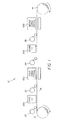
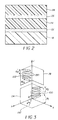
- finished goods roll 14 is a liquid crystal display compensation film, fabricated as web 16 built up from multiple layers of material, with the components shown in Figure 2. These materials are linear photo-polymerization media (LPP) and liquid crystal polymer media (LCP).
- LPP linear photo-polymerization media
- LCP liquid crystal polymer media
- a clear substrate layer 18 is provided on source roll 12.
- clear substrate layer 18 is made of triacetyl cellulose.
- An LPP1 layer 22 is added at an LPP1 layer application station 30.
- a first irradiation station 20a treats LPP1 layer 22 to provide a predetermined molecular arrangement, crosslinking polymers to obtain optical alignment with a preferred tilt angle.
- an LCP1 layer 24 is affixed to treated LPP1 layer 22 at an LCP1 layer application station 32.
- a first curing station 40a cures LCP1 layer 24 on top of LPP1 layer 22.
- an LPP2 layer 26 is applied at an LPP2 layer application station 34.
- LPP2 layer 26 is treated at a second irradiation station 20b to provide alignment that, in the plane of web 16, is orthogonal to the molecular arrangement provided to LPP1 layer 22.
- an LCP2 layer 28 is applied at an LCP2 layer application station 36 and cured at a second curing station 40b. The manufactured compensation film is then wound onto finished goods roll 14.
- LPP layers are very thin, on the order of approximately 50 nm.
- web 16 is relatively wide, with widths exceeding 1m.
- irradiation stations 20a and 20b provide linearly polarized UV-B irradiation, nominally 280- 320 nm. Exposure doses are provided at levels near 10-15 mJ/cm 2 . Exposure uniformity within +/- 30% is needed in order to prevent "hot spots" at midpoints in the width of web 16 and to spread the exposure energy sufficiently to the sides of web 16. Most important for proper treatment of LPP1 layer 22 and LPP2 layer 26 is providing polarized light having a very consistent direction of polarization, within 1 degree at any point on web 16.
- Curing stations 40a and 40b apply some form of radiant energy suitable for curing LCP layer 24 and LCP2 layer 28.
- UV-B wavelengths are avoided to minimize the impact of curing operation on LPP1 layer 22 and LPP2 layer 26 once treated.
- UV-A wavelengths are used for curing.
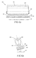
- FIG. 3 there is shown a 3-dimensional geometric representation of LCD layer alignment, relative to an XYZ coordinate system.
- the orientation of discotic liquid crystal structures 190 is shown for LCP2 layer 28.
- the lower section of Figure 3 shows orientation for LCP 1 layer 24.
- Optic axes 100 and 102 are indicated for LCP 1 layer 24 and LCP2 layer 28 respectively.
- alignment processing arranges discotic structures 190 so that optic axes 100 and 102 each have an appropriate tilt angle ⁇ and and/or azimuthal angle ⁇ .
- Azimuthal angle ⁇ is in an XY plane of substrate 192, from the X axis, parallel to web 16 within the exposure zone of irradiation station 20a or 20b of Figure 1.
- Tilt angle ⁇ is in the Z direction, up from the origin.
- Optic axes 100 and 102 should be orthogonal with respect to each other, within a tolerance of a few degrees.
- Azimuthal angle ⁇ of optic axis 100, 102 is, in part, a factor of dopant in the anisotropic LCP material.
- Tilt angle ⁇ is, in large part, a factor of the incident light angle, exposure dose, and polarization and can vary somewhat over a range from ⁇ 1 , to ⁇ 2 . Obtaining a quality compensation film is, then, dependent on maintaining a suitable incident angle, proper exposure dosage, and uniform polarization characteristics.
- the orthogonal directions of tilt angle orientation are as follows: a 0-degree orientation is provided substantially parallel to the direction of web movement; a 90-degree orientation is provided orthogonal to the 0-degree orientation, substantially in the cross-web direction.
- a crossed 45-degree alignment arrangement could be fabricated, providing orthogonal alignment to multiple layers using the apparatus and method of the present invention.
- Irradiation apparatus 60 as used, with variations, within irradiation stations 20a and 20b to apply UV light over an irradiation zone onto web 16.
- Irradiation apparatus 60 comprises a hood assembly 70 that generates and directs source radiation across the full width of web 16 and a light conditioning assembly 74 for controlling light divergence, for directing light with the desired incident angle, and for polarizing this source radiation.
- a light source 64 provides source radiation at the preferred wavelength and power levels. Cooling is provided, such as by a cooling tube 66 or other device. Cooling tube 66 could be air- or water-cooled, for example. An air tube 62 may also be provided for cooling purposes. Cooling tube 66 also provides some amount of UV-C and IR filtering.
- a prism array 72 is disposed in the radiation path. Prism array 72 helps to reduce the divergence angle of light along the length of irradiation apparatus 60. An optional coating 71 may be provided such as to prevent UV-B reflection, for example.
- a louver array 80 is then disposed below prism array 72. As is described subsequently, louver array 80 also helps to reduce the divergence angle and to direct light in an intended direction toward the surface of web 16.
- a polarizer 90 provides the necessary amount of polarization for exposure irradiation, as is also described subsequently.
- Light source 64 could be, for example, an Hg medium pressure long arc lamp, such as those available from Nordson Corporation, Amherst, OH, for example.
- Figure 4 shows one configuration of irradiation apparatus 60. As is described subsequently, different arrangements of support components such as prism array 72 and louver array 80 are provided for 0- and 90-degree configurations.
- filter 82 comprises one or more fused silica plates, having high reflectance to visible and UV-A light.
- Irradiation station 20a or 20b may house more than one irradiation apparatus 60. By using a number of irradiation apparatus 60 in series, first or second irradiation station 20a or 20b can provide additional exposure dosage capacity, effectively providing a wider exposure zone, enabling accelerated processing by processing apparatus 10.
- first irradiation station 20a may have one or more irradiation apparatus 60 for providing alignment in one direction.
- second irradiation station 20b may also have more than one irradiation apparatus 60 for providing alignment in a second, orthogonal direction.
- the deployment of multiple irradiation apparatus 60 units increases the available exposure dosage for treating the LPP medium. Slightly different configurations of irradiation apparatus 60 are used for the 0-degree and 90-degree configurations used within first and second irradiation stations 20a and 20b respectively. However, only minor modifications are needed to adapt irradiation apparatus 60 for the 0-degree or for the 90-degree configuration.
- irradiation apparatus 60 for the 0-degree configuration used within first irradiation station 20a.
- web 16 movement direction is out from the page.
- irradiation apparatus 60 is tilted at an angle H relative to the surface of web 16. This tilt could be obtained by tilting irradiation apparatus 60 or by routing web 16 at an oblique angle relative to irradiation apparatus 60.
- This arrangement provides exposure light at the optimum incident angle for obtaining 0-degree alignment.
- a reflector 68 is positioned along the length of light source 64, collecting and redirecting light emitted from light source 64.
- irradiation apparatus 60 for the 90-degree configuration used within second irradiation station 20b.
- the direction of movement of web 16 is out from the page.
- irradiation apparatus 60 is not tilted at an angle relative to the surface of web 16.
- the angle of incident light must be obliquely diverted in the cross-web direction, as described subsequently, either by using a divertive prism array 104 as is shown in Figures 7b and 9, or by changing the angular orientation of louver array 80, as is shown in Figure 8a.
- hood assembly 70 One function of hood assembly 70 is to minimize the angular divergence of light incident on polarizer 90.
- FIG 8b there is shown a side view of irradiation apparatus 60 in the 90-degree configuration.
- the arrangement of light source 64 and reflector 68 within hood assembly 70 effectively constrains the angular divergence of exposure light in the web travel direction, as indicated by angle F.
- angle F is constrained to approximately 45 degrees. This angular constraint in the web travel direction applies for both 0-degree and 90-degree configurations.
- Control of angular divergence in the orthogonal direction, across the web can be performed by a number of different structures, singly or in combination, depending on the 0- or 90-degree configuration that is used.
- the simplest means for control of angular divergence is an opaque louver array 80, with louvers vertically disposed as shown in Figure 5. With louver array 80 arranged as shown in Figure 5, angular divergence is constrained as a factor of louver spacing.
- Prism array 72 comprises a sequence of symmetric prisms 73. Each prism 73 has the same dimensions and is extended lengthwise along the direction of travel of web 16. In a preferred embodiment, height h is approximately 0.5 in., base B is approximately 1 in.; angle ⁇ 1 is 90 degrees, angles ⁇ 2 and ⁇ 3 are each nominally 45 degrees. Other dimensional characteristics could be applied; prisms 73 could alternately vary in dimension along prism array 72. Prisms may have the linear arrangement of Figure 12a or some modified arrangement, such as staggering of individual prisms 73 to minimize patterning effects. Prism array 72 is most effective in the 90-degree configuration shown in Figure 8a, boosting light efficiency in this configuration.
- Figure 12b shows the operation of prism array 72 as it cooperates with light source 64 and reflector 68. Rays R from any point on light source 64 are emitted over a broad range of angles. Upon passing through prism array 72, rays R are refracted to narrow the range of angles. As can be seen in Figure 12b, the reflective properties of prisms 73 are also employed, in conjunction with reflector 68, to redirect and thereby re-use some of the light incident at a range of angles.
- louver array 80 arrangement there can be a number of adaptations of the louver array 80 arrangement shown in Figure 5.
- an irradiation station 20a or 20b comprises multiple irradiation apparatus 60 in series
- louvers in one irradiation apparatus 60 be offset from louvers in a paired irradiation apparatus 60.
- Unequal louver spacing can also be used.
- louver array 80 is disposed as shown in Figure 10.
- individual louvers 81 are at a suitable angle for directing light rays R from a source point P toward web 16.
- each louver 81 has a reflective side 83 and a non-reflective side 84.
- louver array 80 Rays R at the optimal angle simply pass through louver array 80. Rays R incident upon reflective side 83 are thereby diverted, where possible, to a more suitable incident angle. Other rays R that cannot be readily diverted are absorbed at non-reflective side 84. As a result, the range of incidence angles obtained is acceptable for alignment in the 90-degree orientation. Louvers 81 are spaced to limit the divergence angle of incident light supplied from light source 64.
- divertive prism array 104 An alternative arrangement for diverting exposure irradiation from hood assembly 70 uses divertive prism array 104 as shown in the front view of Figure 9.
- divertive prism array 104 the operation of divertive prism array 104 is represented.
- individual prisms 105 each divert incident light rays R by refraction, redirecting the light at a suitable incident angle.
- Each prism 105 comprises an opaque surface 106 for absorbing rays R that cannot be satisfactorily redirected.
- Opaque surface 106 is typically an absorptive coating.
- prisms 105 may be the same size or may vary in size across divertive prism array 104.
- FIG 13 there is shown, from a front view, how divertive prism array 104 cooperates with prism array 72 in an alternate embodiment.
- prism array 72 constrains angular divergence of rays R from source point P, as was described with reference to Figure 12b. Rays R are then redirected at a suitable incident angle for alignment in the preferred orientation.
- Polarizer 90 works best when used with light having a reduced divergence angle and when placed in close proximity to web 16.
- Polarizer segments 91 are wire grid polarizers, typically three inch square in a preferred embodiment, tiled together as shown.
- Polarizer 90 employs a number of polarizer segments 91, preferably disposed at an angle relative to the movement of web 16. The angular offset compensates for possible streaking effects from boundaries between individual polarizer segments 91.
- a grid frame 96 and a cover frame 94 are used to hold polarizer segments 91 in place, sandwiched between masks 92.
- polarizer 90 is rotatable. That is, the complete polarizer 90 assembly can be rotated to effectively change the principal axis of polarization with respect to the exposure zone of web 16. Alternately, individual polarizer segments 91 can be rotated so that polarizer 90 can be adapted to provide a range of angles.
- Wire grid polarizers are used as polarizer segments 91 in a preferred embodiment due to their capability to withstand high temperatures and suitable polarization characteristics. Generally, polarization of 3:1 or better is acceptable; 5:1 provides a preferred ratio for alignment. Wire grid polarizers offer advantages due to their inherent heat resilience and reduced thickness. Because these devices are generally less sensitive to angular variation than are Brewster plate polarizers or other polarizer devices, wire grid polarizers do not require collimated light. Additionally, because these devices are reflective, some amount of unused light can be reflected back and, potentially, re-used. Wire grid polarizers can be easily oriented to provide 0-degree and 90-degree alignment simply by rotating the wire direction of polarizer segments 91 within the plane of polarizer 90.
- polarizers 90 could be used, provided they are capable of operating under relatively high temperature conditions. Brewster plates made of fused silica or quartz could also be used for alignment in the movement direction of web 16, however, size and weight constraints limit the feasibility of such a solution for large scale irradiation. It would also be difficult to maintain a uniform principal axis of polarization when using Brewster plate devices. Moreover, as is noted in the background section of this application, a Brewster plate polarizer would not be well-suited for cross-web irradiation, particularly where a long-arc lamp is used as light source 64. Interference-type polarizers that also employ Brewster plate principles could alternately be used; however, these polarizers are not dimensionally advantageous and are also poorly suited for cross-web irradiation.
- polarizer segment 91 could employ a Beilby-layer polarizer, such as those available from Sterling Optics, Inc.
- a matrix arrangement similar to that shown in Figures 14a and 14b would also be practicable when using Beilby-layer devices.
- the corresponding polarizer segments 91 could be larger when using these devices than with wire grid polarizers.
- polarizer 90 is optimally positioned parallel to the surface of web 16 within the exposure zone.
- polarizer 90 may be parallel to the base of hood assembly 70, parallel to web 16, or at some intermediate angle. There may be some advantages to using angles that maximize levels of irradiance and provide highly uniform polarization, particularly with the 0-degree arrangement.
- wire grid and Beilby-layer polarizers maintain a uniform principal axis of polarization for light over a range of incident angles.
- polarizer 90 when fabricated using these devices, can be tilted about an axis parallel to the length of light source 64 without noticeable effect on uniformity of polarization direction. Tilt angles of up to about 30 degrees with respect to the surface of web 16 can be used without affecting the performance of polarizer 90.
- light source 64 is a medium-pressure mercury arc lamp.
- These devices can have a power input approaching or exceeding 400 watts/inch of lamp length and have a favorably long lamp life. This approach provides the advantages of using a single bulb that has relatively long useful life (1,000 hours, nominal) and can be readily changed with minimal disruption to equipment.
- light source 64 alternatives include mercury short arc lamps, typically having 10-15 kW input. However, mercury short arc lamps can be more expensive and typically have a shorter useful life than medium-pressure arc lamps.
- Figure 15 there is shown an arrangement using multiple light sources 164a, 164b, 164c, 164d, 164e, and 164f. In order to span the width of web 16, light sources 164a, 164b, 164c, 164d, 164e, and 164f are grouped, staggered to leave no perceptible gaps or boundaries.
- UV-C light (200-270 nm), for example, appears to be detrimental to LPP crosslinking needed for alignment.
- One method for removing UV-C wavelengths employs an absorbing plate of WG 280 for example.
- UV-A, visible, and infrared light are considered superfluous, however, to minimize heating and other unwanted side effects, the preferred embodiment uses an optional filter 82 to remove this unwanted light from the system. Additional filtering is also provided near light source 64 by cooling tube 66, particularly where water is used, as noted above.
- filter 82 follows louver array 80 and prism array 72 in the optics path. With this arrangement, filter 82 accepts incident light over a more controlled angle of divergence. However, filter 82 could be positioned at alternate points in the optics path.
- hood assembly 70 is at right angles to the direction of web 16 movement in the preferred embodiment, other arrangements are possible.
- hood assembly 70 could be disposed at a diagonal relative to web 16.
- Other types of light sources could be employed, providing that a generally uniform irradiation is obtained.
- Irradiation apparatus 60 can also be adapted to suit requirements for obtaining the desired direction of polarization and pretilt.
- irradiation apparatus 60 used for the 90-degree configuration uses both prism array 72 and louver array 80.
- irradiation apparatus 60 does not use louver array 80.
- each irradiation apparatus 60 can be equipped with either louver array 80 or prism array 72 or with both louver array 80 and prism array 72.
- louver array 80 may be angled and configured as described earlier with reference to Figure 10. Alternately, the combination using both prism array 72 and divertive prism array 104 could be used.
- LPP layers are orthogonally aligned in the direction of travel of web 16 and in the cross-web direction.
- a different set of orthogonal angles could be used.
- alignment angles could be at 45-degrees with respect to the edges of web 16.
- Alternate system arrangements for processing apparatus 10 could employ a single irradiation apparatus 60 for processing a roll of media with one alignment layer, aligned in a 45-degree orientation.
- a second alignment layer having 135-degree alignment could be fabricated separately using the same irradiation apparatus 60. Then, both orthogonal layers could be laminated together in an orthogonal arrangement.
- Additional light conditioning components could be used in the optics path, such as for additional filtering.
- a diffuser such as a holographic diffuser, could be employed for improving uniformity of irradiance.
- irradiation apparatus 60 of the present invention provides a compact, energy-efficient device for exposing a wide-area substrate with light radiation having a uniform polarization direction. Adaptable for providing incident light in orthogonal directions, irradiation apparatus 60 can be advantageously deployed in a roll-to-roll manufacturing environment for fabricating web-fed multilayered liquid crystal media having orthogonally oriented alignment layers.
Landscapes
- Physics & Mathematics (AREA)
- Nonlinear Science (AREA)
- Chemical & Material Sciences (AREA)
- Crystallography & Structural Chemistry (AREA)
- General Physics & Mathematics (AREA)
- Optics & Photonics (AREA)
- Mathematical Physics (AREA)
- Liquid Crystal (AREA)
- Polarising Elements (AREA)
Abstract
Description
Claims (10)
- An optical exposure apparatus for forming an alignment layer onto a web-fed substrate, the apparatus comprising:(a) an irradiation apparatus for directing an incident ultraviolet light toward the substrate at a predetermined average angle of inclination, over an exposure zone spanning the full width of the substrate, comprising:(a1) a light source for providing said incident ultraviolet light;(a2) light directing means for directing said incident ultraviolet light at said predetermined average angle of inclination relative to the substrate surface; and(b) a polarizer disposed between said light directing means and the substrate and rotatably oriented to maintain a principal axis of polarization having a predetermined orientation with respect to the web movement direction, said principal axis of polarization independent of said angle of inclination.
- An optical exposure apparatus according to claim 1 wherein said irradiation apparatus further comprises a reflector.
- An optical exposure apparatus according to claim 1 further comprising means for filtering unwanted wavelengths emitted from said light source.
- An optical exposure apparatus according to claim 1 wherein said light source comprises a plurality of lamps.
- An optical exposure apparatus according to claim 1 wherein said light source comprises a long-arc UV lamp.
- An optical exposure apparatus according to claim 1 wherein said first principal axis of polarization is parallel to the movement direction of said substrate.
- An optical exposure apparatus according to claim 1 wherein said polarizer comprises a plurality of wire grid polarizers.
- An optical exposure apparatus according to claim 1 wherein said polarizer comprises a Beilby-layer polarizer.
- An optical exposure apparatus according to claim 1 wherein said irradiation apparatus is disposed at a predetermined tilt angle, relative to said exposure zone, along a tilt axis that extends across the width of the moving substrate.
- An optical exposure apparatus according to claim 1 wherein said polarizer comprises a matrix of wire grid polarizers, each said wire grid polarizer selectively oriented at a first angle for providing polarization along said first principal axis of polarization or oriented at a second angle for providing polarization along said second principal axis of polarization
Applications Claiming Priority (2)
| Application Number | Priority Date | Filing Date | Title |
|---|---|---|---|
| US194750 | 1988-05-17 | ||
| US10/194,750 US6874899B2 (en) | 2002-07-12 | 2002-07-12 | Apparatus and method for irradiating a substrate |
Publications (2)
| Publication Number | Publication Date |
|---|---|
| EP1380873A2 true EP1380873A2 (en) | 2004-01-14 |
| EP1380873A3 EP1380873A3 (en) | 2004-04-21 |
Family
ID=29735352
Family Applications (1)
| Application Number | Title | Priority Date | Filing Date |
|---|---|---|---|
| EP03077020A Withdrawn EP1380873A3 (en) | 2002-07-12 | 2003-06-30 | Apparatus and method for irradiating a substrate |
Country Status (6)
| Country | Link |
|---|---|
| US (2) | US6874899B2 (en) |
| EP (1) | EP1380873A3 (en) |
| JP (1) | JP2004163881A (en) |
| KR (1) | KR20040007330A (en) |
| CN (1) | CN1475819A (en) |
| TW (1) | TWI278015B (en) |
Cited By (3)
| Publication number | Priority date | Publication date | Assignee | Title |
|---|---|---|---|---|
| EP1637922A1 (en) * | 2004-09-16 | 2006-03-22 | Ushiodenki Kabushiki Kaisha | Process for alignment by irradiation with linearly polarised light |
| EP1909136A3 (en) * | 2006-09-28 | 2008-05-14 | Giesecke & Devrient GmbH | Illumination station |
| CN112366021A (en) * | 2020-11-09 | 2021-02-12 | 中国工程物理研究院核物理与化学研究所 | Equipment and method for realizing homogenization of reactor irradiation parameters |
Families Citing this family (44)
| Publication number | Priority date | Publication date | Assignee | Title |
|---|---|---|---|---|
| US7304719B2 (en) * | 2004-03-31 | 2007-12-04 | Asml Holding N.V. | Patterned grid element polarizer |
| US7413317B2 (en) * | 2004-06-02 | 2008-08-19 | 3M Innovative Properties Company | Polarized UV exposure system |
| US7466484B2 (en) * | 2004-09-23 | 2008-12-16 | Rohm And Haas Denmark Finance A/S | Wire grid polarizers and optical elements containing them |
| JP4506412B2 (en) * | 2004-10-28 | 2010-07-21 | ウシオ電機株式会社 | Polarizing element unit and polarized light irradiation device |
| JP4604661B2 (en) * | 2004-11-05 | 2011-01-05 | ウシオ電機株式会社 | Polarized light irradiation device for photo-alignment |
| KR20060042481A (en) * | 2004-11-09 | 2006-05-15 | 엘지전자 주식회사 | Liquid Crystal Display Including Reflective Polarizer |
| JP2008522226A (en) * | 2004-11-30 | 2008-06-26 | アグーラ テクノロジーズ インコーポレイテッド | Application and fabrication technology of large-scale wire grid polarizer |
| US7351346B2 (en) * | 2004-11-30 | 2008-04-01 | Agoura Technologies, Inc. | Non-photolithographic method for forming a wire grid polarizer for optical and infrared wavelengths |
| JP4683998B2 (en) * | 2005-05-09 | 2011-05-18 | 富士フイルム株式会社 | Ultraviolet irradiation device, optical compensation sheet, and polarizing plate and liquid crystal display device using the same |
| JP4606242B2 (en) * | 2005-05-09 | 2011-01-05 | 富士フイルム株式会社 | Ultraviolet irradiation device, functional film, and polarizing plate and liquid crystal display device using the same |
| EP2511758A1 (en) | 2005-08-19 | 2012-10-17 | RealD Inc. | Stereoscopic eyewear |
| JP4815995B2 (en) * | 2005-10-24 | 2011-11-16 | ウシオ電機株式会社 | Polarized light irradiation device for photo-alignment |
| JP4950514B2 (en) * | 2006-02-27 | 2012-06-13 | 株式会社 日立ディスプレイズ | Manufacturing method and manufacturing apparatus for liquid crystal display device |
| JP2007279424A (en) * | 2006-04-07 | 2007-10-25 | Three M Innovative Properties Co | Privacy filter sheet and display device containing the same |
| US20080129930A1 (en) * | 2006-12-01 | 2008-06-05 | Agoura Technologies | Reflective polarizer configuration for liquid crystal displays |
| JP2008268466A (en) * | 2007-04-19 | 2008-11-06 | Fujinon Corp | Phase difference compensation element and its manufacturing method |
| US8643822B2 (en) * | 2007-07-03 | 2014-02-04 | Jds Uniphase Corporation | Non-etched flat polarization-selective diffractive optical elements |
| KR101383930B1 (en) * | 2008-12-24 | 2014-04-10 | 엘지디스플레이 주식회사 | Light irradiation apparatus |
| JP5287737B2 (en) * | 2010-01-13 | 2013-09-11 | ウシオ電機株式会社 | Polarized light irradiation device |
| TWI409594B (en) * | 2010-11-16 | 2013-09-21 | Au Optronics Corp | Exposure light assembly and exposure machine |
| JP5205498B2 (en) * | 2011-08-08 | 2013-06-05 | 株式会社ジャパンディスプレイイースト | Light irradiation device |
| JP5200271B1 (en) * | 2012-01-25 | 2013-06-05 | ウシオ電機株式会社 | Polarized light irradiation device |
| JP5056991B1 (en) * | 2012-02-02 | 2012-10-24 | ウシオ電機株式会社 | Polarized light irradiation device |
| KR101678512B1 (en) * | 2012-03-22 | 2016-11-22 | 가부시키가이샤 히다치 고쿠사이 덴키 | Method for manufacturing semiconductor device, method for processing substrate, substrate processing device and recording medium |
| KR101991521B1 (en) | 2012-04-20 | 2019-06-20 | 이와사키 덴끼 가부시키가이샤 | Polarizer unit, jig for adjusting, lamp replacement stage and irradiation apparatus |
| JP5163825B1 (en) * | 2012-04-23 | 2013-03-13 | ウシオ電機株式会社 | Polarized light irradiation device |
| TWI585387B (en) | 2012-07-18 | 2017-06-01 | 岩崎電氣股份有限公司 | Polarization measuring process, polarization measuring apparatus, polarization measuring system and photo-alignment irradiation apparatus |
| JP2013152433A (en) * | 2012-11-30 | 2013-08-08 | Ushio Inc | Polarization light irradiation apparatus |
| JP6201310B2 (en) * | 2012-12-14 | 2017-09-27 | 東芝ライテック株式会社 | Polarized light irradiation device |
| JP5821860B2 (en) * | 2013-01-21 | 2015-11-24 | ウシオ電機株式会社 | Polarized light irradiation device |
| US9786529B2 (en) * | 2013-03-11 | 2017-10-10 | Applied Materials, Inc. | Pyrometry filter for thermal process chamber |
| TWI509331B (en) * | 2013-08-01 | 2015-11-21 | Far Eastern New Century Corp | Method for manufacturing a retardation film |
| CN104375229A (en) * | 2013-08-14 | 2015-02-25 | 远东新世纪股份有限公司 | Manufacturing method of retardation film |
| JP6326746B2 (en) * | 2013-09-10 | 2018-05-23 | 東芝ライテック株式会社 | Polarized light irradiation device |
| KR102222005B1 (en) * | 2014-01-09 | 2021-03-04 | 삼성디스플레이 주식회사 | Exposure apparatus and exposure method using the same |
| US20160231176A1 (en) | 2015-02-05 | 2016-08-11 | Polarization Solutions, Llc | Light irradiation device having polarization measuring mechanism |
| JP6766370B2 (en) * | 2015-02-18 | 2020-10-14 | 大日本印刷株式会社 | Polarizer, polarizer holder, and photoaligner |
| KR101691570B1 (en) * | 2015-03-30 | 2016-12-30 | 주식회사 아바코 | Exposure apparatus |
| JP6566749B2 (en) * | 2015-07-01 | 2019-08-28 | 株式会社ソニー・インタラクティブエンタテインメント | Image sensor, image sensor, and information processing apparatus |
| CN105607351B (en) * | 2016-01-04 | 2019-03-12 | 京东方科技集团股份有限公司 | An ultraviolet curing device, a frame sealing glue curing system and a frame sealing glue curing method |
| TW201921131A (en) * | 2017-08-09 | 2019-06-01 | 日商V科技股份有限公司 | Photo-aligning exposure device |
| KR102010962B1 (en) * | 2017-11-08 | 2019-08-13 | 엘지디스플레이 주식회사 | Optical film and display device using the same |
| CN113031349B (en) * | 2021-03-22 | 2021-12-31 | 惠科股份有限公司 | Photo-alignment device and photo-alignment method |
| JPWO2023085308A1 (en) * | 2021-11-11 | 2023-05-19 |
Family Cites Families (34)
| Publication number | Priority date | Publication date | Assignee | Title |
|---|---|---|---|---|
| FR2564605B1 (en) | 1984-05-18 | 1987-12-24 | Commissariat Energie Atomique | LIQUID CRYSTAL CELL CAPABLE OF PRESENTING A HOMEOTROPIC STRUCTURE, WITH BIREFRINGENCE COMPENSATED FOR THIS STRUCTURE |
| US4974941A (en) | 1989-03-08 | 1990-12-04 | Hercules Incorporated | Process of aligning and realigning liquid crystal media |
| US5327285A (en) * | 1990-06-11 | 1994-07-05 | Faris Sadeg M | Methods for manufacturing micropolarizers |
| DE59209499D1 (en) | 1991-07-26 | 1998-10-22 | Rolic Ag | Oriented photopolymers and processes for their manufacture |
| US6160597A (en) | 1993-02-17 | 2000-12-12 | Rolic Ag | Optical component and method of manufacture |
| SG50569A1 (en) | 1993-02-17 | 2001-02-20 | Rolic Ag | Optical component |
| US5410422A (en) | 1993-03-03 | 1995-04-25 | Tektronix, Inc. | Gray scale liquid crystal display having a wide viewing angle |
| US5619352A (en) | 1994-04-04 | 1997-04-08 | Rockwell International Corporation | LCD splay/twist compensator having varying tilt and /or azimuthal angles for improved gray scale performance |
| JP3075917B2 (en) | 1994-05-27 | 2000-08-14 | シャープ株式会社 | Liquid crystal display device, its manufacturing method and its manufacturing device |
| DE19519928B4 (en) | 1994-05-31 | 2006-04-27 | Fuji Photo Film Co., Ltd., Minami-Ashigara | Optical compensation film and liquid crystal display unit |
| US5853801A (en) | 1995-09-04 | 1998-12-29 | Fuji Photo Film Co., Ltd. | Process for the preparation of continuous optical compensatory sheet |
| DE19703682B9 (en) | 1996-02-01 | 2006-11-23 | Lg. Philips Lcd Co., Ltd. | UV light irradiation apparatus for photo alignment method and irradiation method using the same |
| WO1997044702A1 (en) | 1996-05-17 | 1997-11-27 | Philips Electronics N.V. | Compensator, liquid-crystal display device and retardation foil |
| JPH1073722A (en) * | 1996-08-30 | 1998-03-17 | Sony Corp | Polarizing optical element and manufacturing method thereof |
| JP3146998B2 (en) * | 1996-09-12 | 2001-03-19 | ウシオ電機株式会社 | Polarized light irradiator for photo-alignment of alignment film of liquid crystal display device |
| US6292296B1 (en) | 1997-05-28 | 2001-09-18 | Lg. Philips Lcd Co., Ltd. | Large scale polarizer and polarizer system employing it |
| US6307609B1 (en) | 1997-08-05 | 2001-10-23 | Wayne M. Gibbons | Polarized light exposure systems for aligning liquid crystals |
| US6061138A (en) | 1997-08-05 | 2000-05-09 | Elsicon, Inc. | Optical exposure systems and processes for alignment of liquid crystals |
| TW536644B (en) | 1997-10-29 | 2003-06-11 | Ushio Electric Inc | Polarized light radiation device for alignment film of liquid crystal display element |
| JPH11142850A (en) | 1997-11-05 | 1999-05-28 | Hitachi Ltd | Polarized light irradiation method and apparatus |
| US6210644B1 (en) | 1998-04-23 | 2001-04-03 | The Procter & Gamble Company | Slatted collimator |
| KR100323731B1 (en) | 1998-11-06 | 2002-05-09 | 구본준, 론 위라하디락사 | Light irradiating device |
| JP4153090B2 (en) * | 1998-06-22 | 2008-09-17 | 富士フイルム株式会社 | Optical compensation sheet manufacturing method |
| US5936691A (en) | 1998-07-17 | 1999-08-10 | Kent State University | Method of preparing alignment layer for use in liquid crystal devices using in-situ ultraviolet exposure |
| JP3384346B2 (en) * | 1999-01-14 | 2003-03-10 | ウシオ電機株式会社 | Polarized light irradiation device for photo alignment of liquid crystal display devices |
| GB9902404D0 (en) | 1999-02-03 | 1999-03-24 | Rolic Ag | Method of imparting preferred alignment, and liquid crystal device elements incorporating a preferred alignment |
| JP2000227595A (en) * | 1999-02-08 | 2000-08-15 | Sony Corp | Manufacturing method of liquid crystal display element |
| US6234634B1 (en) | 1999-07-28 | 2001-05-22 | Moxtek | Image projection system with a polarizing beam splitter |
| JP4427837B2 (en) * | 1999-09-03 | 2010-03-10 | 住友化学株式会社 | Wire grid type polarization optical element |
| US6243199B1 (en) | 1999-09-07 | 2001-06-05 | Moxtek | Broad band wire grid polarizing beam splitter for use in the visible wavelength region |
| JP3603758B2 (en) | 2000-07-12 | 2004-12-22 | ウシオ電機株式会社 | Polarizing element of polarized light irradiation device for photo-alignment of liquid crystal alignment film |
| JP4626039B2 (en) * | 2000-09-26 | 2011-02-02 | コニカミノルタホールディングス株式会社 | Method for producing photo-alignment layer |
| JP2002189301A (en) * | 2000-12-22 | 2002-07-05 | Ushio Inc | Polarized light irradiation device for photo alignment |
| US6791749B2 (en) * | 2001-08-29 | 2004-09-14 | Delpico Joseph | Polarized exposure for web manufacture |
-
2002
- 2002-07-12 US US10/194,750 patent/US6874899B2/en not_active Expired - Lifetime
-
2003
- 2003-05-27 TW TW092114267A patent/TWI278015B/en not_active IP Right Cessation
- 2003-06-10 JP JP2003165570A patent/JP2004163881A/en active Pending
- 2003-06-30 EP EP03077020A patent/EP1380873A3/en not_active Withdrawn
- 2003-07-11 CN CNA031464939A patent/CN1475819A/en active Pending
- 2003-07-11 KR KR1020030047175A patent/KR20040007330A/en not_active Ceased
-
2005
- 2005-01-24 US US11/042,044 patent/US6988811B2/en not_active Expired - Lifetime
Cited By (5)
| Publication number | Priority date | Publication date | Assignee | Title |
|---|---|---|---|---|
| EP1637922A1 (en) * | 2004-09-16 | 2006-03-22 | Ushiodenki Kabushiki Kaisha | Process for alignment by irradiation with linearly polarised light |
| US7507448B2 (en) | 2004-09-16 | 2009-03-24 | Ushiodenki Kabushiki Kaisha | Process for optical alignment |
| EP1909136A3 (en) * | 2006-09-28 | 2008-05-14 | Giesecke & Devrient GmbH | Illumination station |
| CN112366021A (en) * | 2020-11-09 | 2021-02-12 | 中国工程物理研究院核物理与化学研究所 | Equipment and method for realizing homogenization of reactor irradiation parameters |
| CN112366021B (en) * | 2020-11-09 | 2022-09-23 | 中国工程物理研究院核物理与化学研究所 | Equipment and method for realizing homogenization of reactor irradiation parameters |
Also Published As
| Publication number | Publication date |
|---|---|
| US20040008310A1 (en) | 2004-01-15 |
| US6874899B2 (en) | 2005-04-05 |
| TW200403717A (en) | 2004-03-01 |
| EP1380873A3 (en) | 2004-04-21 |
| US20050140885A1 (en) | 2005-06-30 |
| CN1475819A (en) | 2004-02-18 |
| JP2004163881A (en) | 2004-06-10 |
| US6988811B2 (en) | 2006-01-24 |
| KR20040007330A (en) | 2004-01-24 |
| TWI278015B (en) | 2007-04-01 |
Similar Documents
| Publication | Publication Date | Title |
|---|---|---|
| US6874899B2 (en) | Apparatus and method for irradiating a substrate | |
| US6844913B2 (en) | Optical exposure apparatus for forming an alignment layer | |
| US7911696B1 (en) | Large scale polarizer and polarizer system employing it | |
| US5934780A (en) | Polarized light irradiation device for purposes of optical alignment of an alignment layer of a liquid crystal cell element | |
| US9122013B2 (en) | Variable transmission window | |
| KR100510888B1 (en) | Irradiating device for alignment film of liquid crystal display device_ | |
| CN101861535A (en) | Retardation film, production method of retardation film, and display | |
| KR20010022603A (en) | Optical exposure systems and processes for alignment of liquid crystals | |
| US6943930B2 (en) | Method and system for fabricating optical film using an exposure source and reflecting surface | |
| JP2928226B2 (en) | Polarized light irradiation device for photo-alignment of alignment film of liquid crystal display device | |
| JP3603758B2 (en) | Polarizing element of polarized light irradiation device for photo-alignment of liquid crystal alignment film | |
| US20060187547A1 (en) | Polarized light irradiation apparatus polarized light irradiation method, photo alignment film, and retardation film | |
| JP4135557B2 (en) | Polarized light irradiation device for photo-alignment | |
| US20100085640A1 (en) | Polarizing plate and polarizing device comprising the same | |
| JP4046427B2 (en) | Polarizer with large area polarizing plate | |
| WO2009051408A1 (en) | Method for manufacturing cholesteric reflective plarizer with quater wave plate, and reflective plarizer therefrom | |
| CN119731567A (en) | Sheet and method for manufacturing liquid crystal optical element | |
| KR20190094241A (en) | Manufacturing method of retardation film | |
| KR100268004B1 (en) | Large scale polarizer and polarizing device employing it | |
| HK1191101B (en) | Variable transmission window |
Legal Events
| Date | Code | Title | Description |
|---|---|---|---|
| PUAI | Public reference made under article 153(3) epc to a published international application that has entered the european phase |
Free format text: ORIGINAL CODE: 0009012 |
|
| AK | Designated contracting states |
Kind code of ref document: A2 Designated state(s): AT BE BG CH CY CZ DE DK EE ES FI FR GB GR HU IE IT LI LU MC NL PT RO SE SI SK TR |
|
| AX | Request for extension of the european patent |
Extension state: AL LT LV MK |
|
| PUAL | Search report despatched |
Free format text: ORIGINAL CODE: 0009013 |
|
| AK | Designated contracting states |
Kind code of ref document: A3 Designated state(s): AT BE BG CH CY CZ DE DK EE ES FI FR GB GR HU IE IT LI LU MC NL PT RO SE SI SK TR |
|
| AX | Request for extension of the european patent |
Extension state: AL LT LV MK |
|
| RIC1 | Information provided on ipc code assigned before grant |
Ipc: 7F 21V 13/00 B Ipc: 7G 02B 27/00 B Ipc: 7G 21K 5/00 B Ipc: 7G 02F 1/1337 A |
|
| 17P | Request for examination filed |
Effective date: 20040925 |
|
| 17Q | First examination report despatched |
Effective date: 20041118 |
|
| AKX | Designation fees paid |
Designated state(s): DE FR GB |
|
| STAA | Information on the status of an ep patent application or granted ep patent |
Free format text: STATUS: THE APPLICATION IS DEEMED TO BE WITHDRAWN |
|
| 18D | Application deemed to be withdrawn |
Effective date: 20050330 |