EP1380469A2 - Dispositif d'eclairage pour vehicules - Google Patents
Dispositif d'eclairage pour vehicules Download PDFInfo
- Publication number
- EP1380469A2 EP1380469A2 EP03102059A EP03102059A EP1380469A2 EP 1380469 A2 EP1380469 A2 EP 1380469A2 EP 03102059 A EP03102059 A EP 03102059A EP 03102059 A EP03102059 A EP 03102059A EP 1380469 A2 EP1380469 A2 EP 1380469A2
- Authority
- EP
- European Patent Office
- Prior art keywords
- light
- light guide
- cross
- lighting device
- surface areas
- Prior art date
- Legal status (The legal status is an assumption and is not a legal conclusion. Google has not performed a legal analysis and makes no representation as to the accuracy of the status listed.)
- Withdrawn
Links
Images


Classifications
-
- G—PHYSICS
- G02—OPTICS
- G02B—OPTICAL ELEMENTS, SYSTEMS OR APPARATUS
- G02B6/00—Light guides; Structural details of arrangements comprising light guides and other optical elements, e.g. couplings
- G02B6/0001—Light guides; Structural details of arrangements comprising light guides and other optical elements, e.g. couplings specially adapted for lighting devices or systems
-
- B—PERFORMING OPERATIONS; TRANSPORTING
- B60—VEHICLES IN GENERAL
- B60Q—ARRANGEMENT OF SIGNALLING OR LIGHTING DEVICES, THE MOUNTING OR SUPPORTING THEREOF OR CIRCUITS THEREFOR, FOR VEHICLES IN GENERAL
- B60Q3/00—Arrangement of lighting devices for vehicle interiors; Lighting devices specially adapted for vehicle interiors
- B60Q3/60—Arrangement of lighting devices for vehicle interiors; Lighting devices specially adapted for vehicle interiors characterised by optical aspects
- B60Q3/62—Arrangement of lighting devices for vehicle interiors; Lighting devices specially adapted for vehicle interiors characterised by optical aspects using light guides
- B60Q3/64—Arrangement of lighting devices for vehicle interiors; Lighting devices specially adapted for vehicle interiors characterised by optical aspects using light guides for a single lighting device
-
- B—PERFORMING OPERATIONS; TRANSPORTING
- B60—VEHICLES IN GENERAL
- B60Q—ARRANGEMENT OF SIGNALLING OR LIGHTING DEVICES, THE MOUNTING OR SUPPORTING THEREOF OR CIRCUITS THEREFOR, FOR VEHICLES IN GENERAL
- B60Q3/00—Arrangement of lighting devices for vehicle interiors; Lighting devices specially adapted for vehicle interiors
- B60Q3/70—Arrangement of lighting devices for vehicle interiors; Lighting devices specially adapted for vehicle interiors characterised by the purpose
- B60Q3/76—Arrangement of lighting devices for vehicle interiors; Lighting devices specially adapted for vehicle interiors characterised by the purpose for spotlighting, e.g. reading lamps
Definitions
- the invention relates to a lighting device for a vehicle, in particular an interior lamp, with at least one lamp and at least one this assigned light collecting part,
- the illuminant is an ellipsoidal reflector Assigned light collector, which is the light emitted by the illuminant bundles.
- the light beam generated in this way is in one end of a light guide coupled, the other end of a spot to be illuminated is facing. This is guided in the side of the light guide Reflected light using total reflection.
- the opening angle at which the light beam emerges from the light guide corresponds to the opening angle that the Bundle of light before entering the light guide.
- the light guide shines in relatively narrow beam of light.
- the light emitted by an incandescent lamp without the Coupling directly into a light guide using a light collecting part has a larger one Opening angle on than in the arrangement already mentioned with light collecting part.
- the opening angle of the light beam coupled into the light guide is on the one hand from the distance between the emission point of the illuminant and the light entry surface of the Light guide and on the other hand also on the dimensions of the light entry surface dependent. Because here too the opening angle of the light beam when passing through is retained approximately by the light guide, results compared to an illumination device with a light collector also a correspondingly larger opening angle of the light bundle emerging from the light guide.
- the opening angle can be increased by increasing the distance between the Illuminants and the light entry surface are reduced, however, takes in the The amount of light coupled in with increasing distance between the Illuminant and the light entry surface, so that then only a relative poor efficiency of the lighting device results in 0. This is particularly so unfavorable when using a lamp that has a large beam angle Light emits because there is a large distance between the illuminant and the light coupling area is only a very small part of that Illuminant emitted light is coupled into the light guide.
- the converging lens By intermediary a converging lens between the illuminant and the light coupling surface the optical efficiency of the lighting device can be increased
- the converging lens must then have a relatively large diameter have because the illuminant to achieve a light beam with small Opening angle approximately at the focal point of the converging lens and thus in a relatively large one Distance from the converging lens must be arranged.
- the light collecting part as a light guide at least one light entry surface facing the illuminant and at least a spaced-apart light exit surface is formed that the light guide at least two between the light entry surface and the light exit surface side surface regions arranged opposite one another on its outer circumference on which the light guided in the light guide of total reflection subject, and that these side surface areas for focusing the light in such a way run obliquely to each other so that the cross section of the light guide, starting from from the light entry surface to the light exit surface.
- the light bundle guided in the light guide thus emerges from the light guide has a smaller opening angle than before entering the light guide, i.e. the Light rays are "parallelized" when they pass through the light guide.
- the light entry surface of the light bundle element can be close to the light emission point of the lamp can be arranged, the distance between the Light entry surface and the light beam element, possibly even to zero can be reduced.
- an almost complete one can easily be Coupling of the light emitted by the illuminant into the light guide be achieved, i.e. the light beam is almost lossless.
- they extend in pairs mutually assigned side surface areas only over part of the longitudinal extent of the light guide, the light guide in the remaining part of its longitudinal extent at least in sections, preferably a constant cross section having. This measure allows the cross-sectional dimension for a long light guide be limited at the light exit end of the light guide.
- the light guide has at least a first and a second pair of mutually opposite, oblique mutually extending rare surface areas, the direction in which the side surface areas of the first pair are opposite, transverse to that Direction is arranged in which the side surface areas of the second pair are opposite.
- the side surface areas are in the circumferential direction of the Light guide arranged offset to each other.
- the cross section of the light guide can vary expand from a square to a larger square, for example. This in The light guided in the light guide is then in different, transverse to each other extending longitudinal planes of the light guide bundled.
- the light guide at least a first and a second Pair of opposite, diagonally extending Has side surface areas, and that these pairs in the longitudinal direction of the light parent are arranged offset to one another. If necessary, between the mutually offset side surface areas with a light guide section its length can be arranged constant cross-section. Also through these measures a desired light beam can be achieved. It is special possible, the light only in a certain, transverse to the longitudinal extension of the Light guide lying. Bundle level.
- they are each between the side surface areas lying opposite each other in pairs included opening angle in at least two pairs of these side surface areas different sized. If this side surface area in the circumferential direction of the light guide are offset from each other, there is an asymmetrical Light collection.
- a light beam with a rectangular shape can also be used Cross section when passing through the light guide in a light bundle with a square Cross-section be mined.
- the cross section widens of the light guide along the sloping side surface areas from a first cross-sectional shape to a second cross-sectional shape, the second cross-sectional shape corresponds to an extension of the first cross-sectional shape.
- the Optical fiber is then simple in the development of the lighting device Conceivable, for example, using a CAD system.
- the cross-sectional shape of the lighting device can correspond to the respective Desired radiation characteristics of the lighting device can be selected.
- the first cross-sectional shape is a circle and the second cross-sectional shape an ellipse.
- the light guide can be used as Plastic injection molded part can be formed, the geometry of the light guide comparatively inexpensive manufacture of the for the manufacture of the light guide necessary injection molding tool.
- the light guide is also easy to use remove from the injection mold.
- the illuminant assigned to the light guide preferably has a point or circular disk-shaped light emission, which good light coupling into the circular first cross-sectional shape of the light guide allows.
- the Cross section of the light guide along the oblique side surface areas from a circular shape to a cross-sectional shape by two Semicircles and two parallel connecting the ends of these semicircles Straight line is limited.
- this embodiment compared to that a different light distribution with an elliptical exit cross-section.
- the light exit surface has at least one slope that is orthogonal to the longitudinal extension of the light guide arranged plane is inclined, where appropriate at least two of these slopes by at least one step or a paragraph are arranged offset to each other.
- the main direction of emission of the light beam is then inclined at an angle to the longitudinal axis of the light guide.
- At least one illuminant is designed as a surface spotlight, in particular as an electroluminescent film or organic light emitting diode (oLED).
- the Surface spotlights can then be arranged close to the light entry surface of the light guide be so that almost all of the light emitted by the surface radiator can be bundled by means of the light guide.
- One as an interior light for ambient lighting of an interior 1 of a Lighting device designed for vehicle 2 has a carrier part 3 (FIG. 1), on which a lamp 4 and a light guide 5 assigned to it are arranged are.
- the illuminant 4 is designed as a light-emitting diode, which is on one in the drawing Circuit board, not shown, is mounted, the electrical connections for connecting to a power supply (battery) of the vehicle 2.
- the Printed circuit board is on the interior 1 of the vehicle 2 in the use position facing away from the back of the support member 3 and located there Attachment points connected to this.
- the illuminant 4 is behind one Positioned opening 6 which passes through the carrier part 3. In this opening 6 is the Light guide 5 used.
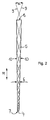
- the light guide 5 is rod-shaped and has a light entry surface 7 at one end facing the illuminant 4 and at its other end facing the interior 1 a light exit surface 8.
- the normal to the outer surface of the light guide 5 is arranged relative to the light beams 9 guided in the light guide 5 such that these are subject to total reflection when they hit the lateral surface.
- the light guide 5 is designed as a light collector, which through the light guide 5 bundles light passing through such that the opening angle ⁇ of the from the Light guide 5 emerging light bundle is smaller than the opening angle ⁇ of Bundle of light before entering the light guide 5. This is achieved in that the outer circumference of the light guide 5 diametrically opposite each other Side surface areas 10 of the light guide 5 so inclined to each other run that the cross section of the light guide 5, starting from the light entry surface 7 to the light exit surface 8. In orthogonal to the longitudinal central axis of the light guide 5 arranged levels run the rare surface areas 10th point symmetrical to the longitudinal center axis of the light guide 5.
- the angle is reduced, under which the light rays 9 to the longitudinal direction Pf or to the longitudinal central axis of the light guide 5 are inclined in the reflection of the light rays 9 to the Side surface areas 10 each by double, between each other opposite side surface areas 10 included opening angle ⁇ of the light guide 5.
- this effect in the Light rays 9, which strongly before entering the light guide 5 against its longitudinal direction Pf are particularly effective since these light beams 9 several times on the side surface regions 10 which run obliquely to one another be reflected.
- the light guide 5 has several, approximately stripes in the longitudinal direction Pf, each diametrical mutually opposite side surface areas 10, which in the circumferential direction of the light guide 5 are arranged offset to one another. They are each between the diametrically opposite side surface areas 10 included opening angle ⁇ in diameter planes that are transverse to each other run, different sizes. This is achieved by the fact that the Cross section of the light guide 5 starting from the light entry surface 7 to the light exit surface 8 from a circular cross section to an elliptical cross section expands, the elliptical cross section by stretching the circular Cross-section is formed. This results in cross-mutually Diameter directions of the light guide 5 a different light beam.
- the Direction in which the circular cross section by stretching in the elliptical Cross section is convertible, is transverse in the use position of the interior light and in particular at right angles to the longitudinal axis 12 of the vehicle 2 or to the latter Direction of travel arranged.
- the interior light emits an oval beam of light from whose largest cross-sectional dimension in the direction of the longitudinal axis 12 of the Vehicle 2 is oriented.
- 4 is the interior light of the vehicle 2 by means of the interior light projected oval light spot marked with a dash-dotted line 13. It is clear recognizable that the light distribution is selected such that one on the driver's seat 14 or the passenger seat 15 sitting by the light of the interior light is illuminated or dazzled. This means that the interior light can operate during the night of the vehicle must be switched on constantly while driving to the between the driver's seat 14 and the passenger seat 15 interior, such e.g. a center console to illuminate uniformly. 4 is for comparison with a dotted line 16 denotes yet another light spot, which is at a Interior lamp with rotationally symmetrical light emission would result.
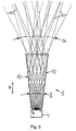
- the light guide 4 has the Illuminant 4 facing end on a square cross-section, which faces the opposite end of the light guide 4 facing the interior 5 continuously to a square cross section with larger dimensions expands.
- the light guide 4 thus has the shape of an obelisk.
- the light guide 4 can also have other angular basic shapes and for example, be formed as a truncated pyramid.
- As the illuminant 4 is in the 5 an area coated with a phosphor Electroluminescent film provided.
- the light exit surface 8 has several Slopes 11, which are orthogonal to the longitudinal direction Pf of the light guide 5 arranged plane are inclined.
- the slopes 11 are each strip-shaped and with their longitudinal extension transverse to their direction of inclination oriented. Slopes arranged next to each other next to each other 11 are oriented parallel to one another with their extension planes. It is a step or a paragraph is provided between each of these slopes 11.
- the Slants 11 at different angles to the orthogonal to Longitudinal direction Pf of the light guide 4 arranged plane may be inclined can.
- the direction of inclination is Slopes 11 are oriented such that the light beam from the windshield 17 of the vehicle 2 is shifted towards the center of the vehicle.
- a light spot is also marked with the dashed line 18 in FIG. 4, which would result in an interior lamp in which the light exit surface is arranged orthogonally to the longitudinal direction Pf of the light guide 5.
- the light collecting part is a light guide 5 at least one light entry surface 7 and at least one spaced-apart light exit surface 8 is formed.
- the light guide 5 has between the light entry surface 7 and the light exit surface 8 at least two oppositely arranged on its outer circumference Side surface areas 10 on which the light guided in the light guide 5 is subject to total reflection.
- the side surface areas 10 run for bundling of the light so obliquely to one another that the cross section of the light guide 5, expanding from the light entry surface 7 to the light exit surface 8.
Applications Claiming Priority (2)
| Application Number | Priority Date | Filing Date | Title |
|---|---|---|---|
| DE10231325A DE10231325A1 (de) | 2002-07-11 | 2002-07-11 | Beleuchtungseinrichtung für Fahrzeuge |
| DE10231325 | 2002-07-11 |
Publications (2)
| Publication Number | Publication Date |
|---|---|
| EP1380469A2 true EP1380469A2 (fr) | 2004-01-14 |
| EP1380469A3 EP1380469A3 (fr) | 2007-06-20 |
Family
ID=29723843
Family Applications (1)
| Application Number | Title | Priority Date | Filing Date |
|---|---|---|---|
| EP03102059A Withdrawn EP1380469A3 (fr) | 2002-07-11 | 2003-07-09 | Dispositif d'eclairage pour vehicules |
Country Status (2)
| Country | Link |
|---|---|
| EP (1) | EP1380469A3 (fr) |
| DE (1) | DE10231325A1 (fr) |
Cited By (10)
| Publication number | Priority date | Publication date | Assignee | Title |
|---|---|---|---|---|
| GB2412722A (en) * | 2004-03-31 | 2005-10-05 | Honda Access Kk | Interior illuminator for automobile |
| WO2008016326A1 (fr) * | 2006-08-04 | 2008-02-07 | Optimal Lighting Partner Olp Ab | Dispositif d'éclairage à guide lumineux |
| EP1974389A2 (fr) * | 2006-01-05 | 2008-10-01 | Illumitex, Inc. | Dispositif optique séparé pour diriger de la lumière depuis une del |
| DE102008039184A1 (de) * | 2008-08-20 | 2010-03-04 | Takata-Petri Ag | Verfahren zum Herstellen eines Bedienelements für ein Kraftfahrzeugteil sowie ein Kraftfahrzeugteil mit einem Bedienelement |
| CN1676372B (zh) * | 2004-03-31 | 2011-07-27 | 株式会社本田阿克塞斯 | 机动车室内照明装置 |
| US8087960B2 (en) | 2006-10-02 | 2012-01-03 | Illumitex, Inc. | LED system and method |
| US8115217B2 (en) | 2008-12-11 | 2012-02-14 | Illumitex, Inc. | Systems and methods for packaging light-emitting diode devices |
| US8263993B2 (en) | 2008-02-08 | 2012-09-11 | Illumitex, Inc. | System and method for emitter layer shaping |
| US8449128B2 (en) | 2009-08-20 | 2013-05-28 | Illumitex, Inc. | System and method for a lens and phosphor layer |
| US8585253B2 (en) | 2009-08-20 | 2013-11-19 | Illumitex, Inc. | System and method for color mixing lens array |
Families Citing this family (6)
| Publication number | Priority date | Publication date | Assignee | Title |
|---|---|---|---|---|
| DE102005042523A1 (de) * | 2005-05-31 | 2006-12-07 | Osram Opto Semiconductors Gmbh | Beleuchtungseinrichtung |
| DE102007054037A1 (de) * | 2007-09-28 | 2009-04-02 | Osram Opto Semiconductors Gmbh | Beleuchtungseinrichtung, Leuchte und Anzeigevorrichtung |
| DE102010039859A1 (de) * | 2010-08-27 | 2012-03-01 | Osram Ag | Leseleuchte für Kraftfahrzeuge |
| DE102012211284A1 (de) | 2012-06-29 | 2014-01-02 | Automotive Lighting Reutlingen Gmbh | Lichtleitelement und Lichtleiter |
| DE102012106025A1 (de) * | 2012-07-05 | 2014-01-09 | Hella Kgaa Hueck & Co. | Beleuchtungsvorrichtung für Fahrzeuge |
| DE102019120751A1 (de) * | 2019-07-31 | 2021-02-04 | Automotive Lighting Reutlingen Gmbh | Lichtmodul für ein Kraftfahrzeug |
Citations (5)
| Publication number | Priority date | Publication date | Assignee | Title |
|---|---|---|---|---|
| EP0534853A1 (fr) * | 1991-09-25 | 1993-03-31 | Marc Hoffman | Lentille solide non-imagerie à refraction double et réflection totale |
| WO1999020937A1 (fr) * | 1997-10-16 | 1999-04-29 | Advanced Optical Technologies, Llc | Systeme d'eclairage dirige utilisant un deflecteur de lumiere conique |
| US6164805A (en) * | 1998-04-20 | 2000-12-26 | Federal-Mogul World Wide, Inc. | Illuminated door handle for a vehicle |
| EP1083090A2 (fr) * | 1999-09-11 | 2001-03-14 | Preh-Werke GmbH & Co. KG | Conducteur de lumière en forme de champignon |
| GB2365962A (en) * | 2000-08-01 | 2002-02-27 | Visteon Global Tech Inc | Collimating lamp with light pipes |
Family Cites Families (5)
| Publication number | Priority date | Publication date | Assignee | Title |
|---|---|---|---|---|
| DE19621148A1 (de) * | 1996-05-14 | 1997-12-04 | Magna Reflex Holding Gmbh | Leuchtelement |
| DE10036812A1 (de) * | 2000-07-28 | 2002-02-07 | Hella Kg Hueck & Co | Beleuchtungseinrichtung |
| DE20019073U1 (de) * | 2000-11-09 | 2001-02-22 | Hella Kg Hueck & Co | Beleuchtungseinrichtung |
| DE20113287U1 (de) * | 2001-08-09 | 2002-01-03 | Hella Kg Hueck & Co | Beleuchtungseinrichtung für Fahrzeuge |
| JP3426226B1 (ja) * | 2002-01-10 | 2003-07-14 | 日本ライツ株式会社 | 導光部材および照明ユニットならびに計器 |
-
2002
- 2002-07-11 DE DE10231325A patent/DE10231325A1/de not_active Withdrawn
-
2003
- 2003-07-09 EP EP03102059A patent/EP1380469A3/fr not_active Withdrawn
Patent Citations (5)
| Publication number | Priority date | Publication date | Assignee | Title |
|---|---|---|---|---|
| EP0534853A1 (fr) * | 1991-09-25 | 1993-03-31 | Marc Hoffman | Lentille solide non-imagerie à refraction double et réflection totale |
| WO1999020937A1 (fr) * | 1997-10-16 | 1999-04-29 | Advanced Optical Technologies, Llc | Systeme d'eclairage dirige utilisant un deflecteur de lumiere conique |
| US6164805A (en) * | 1998-04-20 | 2000-12-26 | Federal-Mogul World Wide, Inc. | Illuminated door handle for a vehicle |
| EP1083090A2 (fr) * | 1999-09-11 | 2001-03-14 | Preh-Werke GmbH & Co. KG | Conducteur de lumière en forme de champignon |
| GB2365962A (en) * | 2000-08-01 | 2002-02-27 | Visteon Global Tech Inc | Collimating lamp with light pipes |
Cited By (17)
| Publication number | Priority date | Publication date | Assignee | Title |
|---|---|---|---|---|
| GB2412722A (en) * | 2004-03-31 | 2005-10-05 | Honda Access Kk | Interior illuminator for automobile |
| GB2412722B (en) * | 2004-03-31 | 2007-09-19 | Honda Access Kk | Interior illuminator for automobile |
| US7287886B2 (en) | 2004-03-31 | 2007-10-30 | Honda Access Corp. | Interior illuminator for automobile |
| CN1676372B (zh) * | 2004-03-31 | 2011-07-27 | 株式会社本田阿克塞斯 | 机动车室内照明装置 |
| EP1974389A2 (fr) * | 2006-01-05 | 2008-10-01 | Illumitex, Inc. | Dispositif optique séparé pour diriger de la lumière depuis une del |
| EP1974389A4 (fr) * | 2006-01-05 | 2010-12-29 | Illumitex Inc | Dispositif optique séparé pour diriger de la lumière depuis une del |
| US7968896B2 (en) | 2006-01-05 | 2011-06-28 | Illumitex, Inc. | Separate optical device for directing light from an LED |
| US8896003B2 (en) | 2006-01-05 | 2014-11-25 | Illumitex, Inc. | Separate optical device for directing light from an LED |
| US9574743B2 (en) | 2006-01-05 | 2017-02-21 | Illumitex, Inc. | Separate optical device for directing light from an LED |
| WO2008016326A1 (fr) * | 2006-08-04 | 2008-02-07 | Optimal Lighting Partner Olp Ab | Dispositif d'éclairage à guide lumineux |
| US8087960B2 (en) | 2006-10-02 | 2012-01-03 | Illumitex, Inc. | LED system and method |
| US8263993B2 (en) | 2008-02-08 | 2012-09-11 | Illumitex, Inc. | System and method for emitter layer shaping |
| DE102008039184A1 (de) * | 2008-08-20 | 2010-03-04 | Takata-Petri Ag | Verfahren zum Herstellen eines Bedienelements für ein Kraftfahrzeugteil sowie ein Kraftfahrzeugteil mit einem Bedienelement |
| US8115217B2 (en) | 2008-12-11 | 2012-02-14 | Illumitex, Inc. | Systems and methods for packaging light-emitting diode devices |
| US8449128B2 (en) | 2009-08-20 | 2013-05-28 | Illumitex, Inc. | System and method for a lens and phosphor layer |
| US8585253B2 (en) | 2009-08-20 | 2013-11-19 | Illumitex, Inc. | System and method for color mixing lens array |
| US9086211B2 (en) | 2009-08-20 | 2015-07-21 | Illumitex, Inc. | System and method for color mixing lens array |
Also Published As
| Publication number | Publication date |
|---|---|
| EP1380469A3 (fr) | 2007-06-20 |
| DE10231325A1 (de) | 2004-02-12 |
Similar Documents
| Publication | Publication Date | Title |
|---|---|---|
| DE102016100207B4 (de) | Signalleuchte | |
| EP2851718B1 (fr) | Dispositif d'éclairage d'un véhicule automobile | |
| DE102006044019B4 (de) | Reflektorstrahler | |
| EP2607774B1 (fr) | Dispositif d'éclairage d'un véhicule automobile avec une surface lumineuse longue et plane | |
| DE102004020708B4 (de) | Projektoroptikgruppe zur Bildung und Projektion einer Richtcharakteristik mit hohem Gradienten für Fahrzeuge | |
| EP1380469A2 (fr) | Dispositif d'eclairage pour vehicules | |
| EP1744096B1 (fr) | Feu pour véhicule automobile | |
| DE102006037797B4 (de) | Kraftfahrzeugleuchte | |
| DE102011085314B3 (de) | Lichtmodul einer Beleuchtungseinrichtung eines Kraftfahrzeugs | |
| DE10022420A1 (de) | Beleuchtungseinrichtung, insbesondere Leuchte, für Kraftfahrzeuge | |
| DE10311072A1 (de) | Fahrzeugleuchte mit LED-Lichtquellen | |
| DE4040020A1 (de) | Beleuchtungseinrichtung fuer fahrzeuge | |
| DE10231326A1 (de) | Leuchteinheit für Fahrzeuge | |
| DE10139578A1 (de) | Innenleuchte für Fahrzeuge | |
| EP1642064A1 (fr) | Phare destine a un vehicule | |
| EP3210827A1 (fr) | Feu de véhicule | |
| DE10356483B4 (de) | Fahrzeugaußenspiegel-Leuchte eines Kraftfahrzeugs | |
| DE102009005351A1 (de) | Lichtleiter für eine Lampe | |
| DE202005010490U1 (de) | Optikkörper | |
| EP1610157A1 (fr) | Système d'éclairage pour un véhicule comprenant un guide de lumière linéaire | |
| DE19857561A1 (de) | Leuchte, insbesondere für Kraftfahrzeuge | |
| DE102011051541B4 (de) | Beleuchtungsvorrichtung für Fahrzeuge | |
| DE102011004349A1 (de) | Beleuchtungseinrichtung eines Kraftfahrzeugs | |
| DE10259236A1 (de) | Innenleuchte für Fahrzeuge | |
| DE19930461A1 (de) | Fahrzeugleuchte |
Legal Events
| Date | Code | Title | Description |
|---|---|---|---|
| PUAI | Public reference made under article 153(3) epc to a published international application that has entered the european phase |
Free format text: ORIGINAL CODE: 0009012 |
|
| AK | Designated contracting states |
Kind code of ref document: A2 Designated state(s): AT BE BG CH CY CZ DE DK EE ES FI FR GB GR HU IE IT LI LU MC NL PT RO SE SI SK TR |
|
| AX | Request for extension of the european patent |
Extension state: AL LT LV MK |
|
| RAP1 | Party data changed (applicant data changed or rights of an application transferred) |
Owner name: HELLA KGAA HUECK & CO. |
|
| PUAL | Search report despatched |
Free format text: ORIGINAL CODE: 0009013 |
|
| AK | Designated contracting states |
Kind code of ref document: A3 Designated state(s): AT BE BG CH CY CZ DE DK EE ES FI FR GB GR HU IE IT LI LU MC NL PT RO SE SI SK TR |
|
| AX | Request for extension of the european patent |
Extension state: AL LT LV MK |
|
| RIC1 | Information provided on ipc code assigned before grant |
Ipc: B60Q 3/02 20060101ALI20070515BHEP Ipc: G02B 6/00 20060101AFI20070515BHEP |
|
| 17P | Request for examination filed |
Effective date: 20071213 |
|
| 17Q | First examination report despatched |
Effective date: 20080123 |
|
| AKX | Designation fees paid |
Designated state(s): AT BE BG CH CY CZ DE DK EE ES FI FR GB GR HU IE IT LI LU MC NL PT RO SE SI SK TR |
|
| STAA | Information on the status of an ep patent application or granted ep patent |
Free format text: STATUS: THE APPLICATION IS DEEMED TO BE WITHDRAWN |
|
| 18D | Application deemed to be withdrawn |
Effective date: 20080603 |