EP1380361A1 - Biegeeinrichtung mit Biegewerkzeug und Biegeantrieb - Google Patents
Biegeeinrichtung mit Biegewerkzeug und Biegeantrieb Download PDFInfo
- Publication number
- EP1380361A1 EP1380361A1 EP02015759A EP02015759A EP1380361A1 EP 1380361 A1 EP1380361 A1 EP 1380361A1 EP 02015759 A EP02015759 A EP 02015759A EP 02015759 A EP02015759 A EP 02015759A EP 1380361 A1 EP1380361 A1 EP 1380361A1
- Authority
- EP
- European Patent Office
- Prior art keywords
- bending
- workpiece
- axis
- drive motor
- drive
- Prior art date
- Legal status (The legal status is an assumption and is not a legal conclusion. Google has not performed a legal analysis and makes no representation as to the accuracy of the status listed.)
- Granted
Links
- 238000005452 bending Methods 0.000 title claims abstract description 130
- 230000005540 biological transmission Effects 0.000 claims description 12
- 238000000034 method Methods 0.000 description 3
- 101100390736 Danio rerio fign gene Proteins 0.000 description 2
- 101100390738 Mus musculus Fign gene Proteins 0.000 description 2
- 230000001419 dependent effect Effects 0.000 description 1
- ZINJLDJMHCUBIP-UHFFFAOYSA-N ethametsulfuron-methyl Chemical compound CCOC1=NC(NC)=NC(NC(=O)NS(=O)(=O)C=2C(=CC=CC=2)C(=O)OC)=N1 ZINJLDJMHCUBIP-UHFFFAOYSA-N 0.000 description 1
- 230000000977 initiatory effect Effects 0.000 description 1
- 238000009434 installation Methods 0.000 description 1
- 238000003754 machining Methods 0.000 description 1
- 230000001360 synchronised effect Effects 0.000 description 1
Images

Classifications
-
- B—PERFORMING OPERATIONS; TRANSPORTING
- B21—MECHANICAL METAL-WORKING WITHOUT ESSENTIALLY REMOVING MATERIAL; PUNCHING METAL
- B21D—WORKING OR PROCESSING OF SHEET METAL OR METAL TUBES, RODS OR PROFILES WITHOUT ESSENTIALLY REMOVING MATERIAL; PUNCHING METAL
- B21D7/00—Bending rods, profiles, or tubes
- B21D7/02—Bending rods, profiles, or tubes over a stationary forming member; by use of a swinging forming member or abutment
- B21D7/024—Bending rods, profiles, or tubes over a stationary forming member; by use of a swinging forming member or abutment by a swinging forming member
Definitions
- the invention relates to a bending device on a bending machine for bending rod and / or rod-like workpieces, in particular of pipes, with a bending tool and a bending drive with swivel arm and Biegeantriebsmotor, wherein the bending tool at least one workpiece abutment and on the swivel arm has at least one pressure piece and the Swivel arm with the pressure piece by means of the bending drive motor around a bending axis running in the workpiece transverse direction pivotable and that of the pressure piece against the associated Workpiece abutment acted upon while swinging the workpiece Swivel arm with the pressure piece bendable around the workpiece abutment is.
- Clamping jaws cooperating with the bending dies are on the swivel arm in the workpiece transverse direction movable.
- the drive from bending die and swivel arm for workpiece bending takes place by means of the electric bending drive motor, the motor shaft via a transmission with a transverse axis of the bending axis Transmission shaft is connected.
- the rotational movement the transmission shaft is a deflection gear in the form of a Bevel gear arranged on the concentric to the bending axis and the Biegematrizen and the swivel arm overlapping Wave transmitted.
- the present invention aims.
- Claim 5 relates to a bending device, which after the Principle of unwinding stretch bending works and for this purpose advantageously of the bending drive concept according to the invention Use.
- the subject of claim 6 is a bending device, by means of which using the inventive Bending drive workpieces in different directions Bend (right / left bending).
- a bending machine 1 comprises a machine base body 2 and a bending device 3 in the form of a bending head, via a boom assembly 4 at one end of the Machine base 2 is attached.
- the machine main body 2 carries a workpiece feed carriage 5 and a Dornschreibzugwagen 6.
- the workpiece feed carriage. 5 is provided with a chuck 7 conventional design, in which in the example shown, a tube 8 is held.
- the Dornschreibzugwagen 6 one is hidden in the figure lying thorn rod mounted in the usual way the workpiece feed carriage 5 and the chuck 7 through the Pipe 8 passes through and at its distance from the Dornschreibzugwagen 6 End has a bending mandrel.
- the bending device 3 has a support structure 9 with a bending tool 10 and also a CNC-controlled bending drive 11 on.
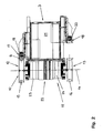
- the bending tool 10 includes workpiece abutments 12, 13 in the form bending dies arranged around a workpiece transverse direction Bending axis 14 rotatable and extending in the circumferential direction Pipe grooves 15, 16 are provided. With the workpiece abutments 12, 13 act as plungers 17, 18 serving Spannbakken of the bending tool 10 together. The pressure pieces 17, 18 have Pipe grooves 19, 20 and are on a pivot arm 21 of the Bending drive 11 movable in the workpiece transverse direction.
- the bending drive 11 comprises a Torque motor running Biegeantriebsmotor 22 and transmission 23, 24.
- the workpiece abutments 12, 13 are by means of of the bending drive motor 22 about the bending axis 14 rotatably, the Swing arm 21 with the pressure pieces 17, 18 is by means of the bending drive motor 22 about the bending axis 14 pivotally.
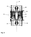
- the bending tool 10 in Fig. 2 the bending drive 11 in the FIGS. 2 and 3 shown.
- the bending drive motor 22 has a rotor 25, a stator 26 and a motor shaft 27.
- the geometric Axis of the motor shaft 27 coincides with the bending axis 14.
- From the motor shaft 27 are opposite to each other Shaft ends 28, 29 formed two motor output sides.
- the transmission 23, connects to the shaft end 29, the gear 24 at.
- the gear 24 with the workpiece abutment 13 is connected.
- the swing arm 21 is both on the output side Gereteelement.des transmission. 23 as well as on the output side gear member of the transmission 24 attached (Fig. 2). This results in a symmetrical Initiation of the applied by the Biegeantriebsmotor Driving force in the swing arm 21.
- 24 is distributed, can each build relatively small.
- the entire bending device 3 is on the support structure 9 at the boom assembly 4 rotatably supported about an axis 30.
- the Bracket assembly 4 in turn can about an axis 31 opposite the machine base 2 are pivoted.
- the rotary or pivoting movements of the bending device 3 about the axis 30 and the boom assembly 4 about the axis 31 are numeric controlled.
- the tube 8 is initially open with bending tool 10 by means of the workpiece feed carriage 5 in the workpiece longitudinal direction opposite the bending tool 10 in the desired Way positioned.
- the bending mandrel inside the tube 8 is by appropriate method of Dornzugzugwagens 6 in his Transferred position of use.
- the bending tool 10 closed.
- the tube is the 8th thereby between the bending die or the workpiece abutment 12 and the associated clamping jaw or the pressure piece 17 is clamped. This results in the in Figs. 1 and 2 shown Conditions.
- torque motors are as Biegeantriebsmotor 22 also other engine types, for example Synchronous motors, conceivable.
- torque motors are suitable for the deviating from the example shown, but quite possible gearless direct connection the motor shaft 27 to the workpiece abutments 12, 13 and / or the swing arm 21.
Landscapes
- Engineering & Computer Science (AREA)
- Mechanical Engineering (AREA)
- Bending Of Plates, Rods, And Pipes (AREA)
Abstract
Description
- Fig. 1
- eine perspektivische Gesamtansicht einer Biegemaschine mit Biegeeinrichtung,
- Fig. 2
- die Biegeeinrichtung nach Fig. 1 in teilgeschnittener Einzeldarstellung und
- Fig. 3
- den Bereich des Biegeantriebsmotors der Biegeeinrichtung nach den Fign. 1 und 2 in teilgeschnittener Darstellung.
Claims (6)
- Biegeeinrichtung an einer Biegemaschine (1) zum Biegen von stangen- und/oder von stabartigen Werkstücken, insbesondere von Rohren (8), mit einem Biegewerkzeug (10) und einem Biegeantrieb (11) mit Schwenkarm (21) und Biegeantriebsmotor (22), wobei das Biegewerkzeug (10) wenigstens ein Werkstückwiderlager (12, 13) sowie an dem Schwenkarm (21) wenigstens ein Druckstück (17, 18) aufweist und der Schwenkarm (21) mit dem Druckstück (17, 18) mittels des Biegeantriebsmotors (22) um eine in Werkstückquerrichtung verlaufende Biegeachse (14) schwenkbar und das von dem Druckstück (17, 18) gegen das zugeordnete Werkstückwiderlager (12, 13) beaufschlagte Werkstück unter Schwenken des Schwenkarms (21) mit dem Druckstück (17, 18) um das Werkstückwiderlager (12, 13) biegbar ist, dadurch gekennzeichnet, dass die Motorwelle (27) des Biegeantriebsmotors (22) parallel zu der Biegeachse (14) ausgerichtet und an beiden Wellenenden (28, 29) mit dem Schwenkarm (21) antriebsverbunden ist.
- Biegeeinrichtung nach Anspruch 1, dadurch gekennzeichnet, dass die Motorwelle (27) des Biegeantriebsmotors (22) koaxial mit der Biegeachse (14) angeordnet ist.
- Biegeeinrichtung nach einem der vorhergehenden Ansprüche, dadurch gekennzeichnet, dass als Biegeantriebsmotor (22) ein Torque-Motor vorgesehen ist.
- Biegeeinrichtung nach einem der vorhergehenden Ansprüche, dadurch gekennzeichnet, dass die Motorwelle (27) des Biegeantriebsmotors (22) an beiden Wellenenden (28, 29) über jeweils ein Getriebe (23, 24) mit dem Schwenkarm (21) antriebsverbunden ist.
- Biegeeinrichtung nach einem der vorhergehenden Ansprüche, dadurch gekennzeichnet, dass mit der Motorwelle (27) des Biegeantriebsmotors (22) wenigstens ein Werkstückwiderlager (12, 13) des Biegewerkzeuges (10) in Form einer Biegematrize antriebsverbunden und dadurch um die Biegeachse (14) drehbar ist und dass das Biegewerkzeug (10) wenigstens ein Druckstück (17, 18) in Form einer an dem Schwenkarm (21) in Werkstückquerrichtung bewegbaren Spannbacke aufweist, wobei das Werkstück zwischen der Biegematrize und der zugeordneten Spannbacke einspannbar und eingespannt unter Drehen der Biegematrize und Schwenken des Schwenkarms mit der Spannbacke um die Biegematrize biegbar ist.
- Biegeeinrichtung nach einem der vorhergehenden Ansprüche, dadurch gekennzeichnet, dass beide Wellenenden (28, 29) der Motorwelle (27) des Biegeantriebsmotors (22) jeweils mit wenigstens einer um die Biegeachse (14) drehbaren Biegematrize antriebsverbunden sind, wobei die den verschiedenen Wellenenden (28, 29) zugeordneten Biegematrizen in Richtung der Biegeachse (14) beidseits des Biegeantriebsmotors (22) angeordnet sind und jeweils mit einer an dem Schwenkarm (21) in Werkstückquerrichtung bewegbaren Spannbacke zusammenwirken und wobei die Biegeeinrichtung (3) um eine in Werkstücklängsrichtung verlaufende Achse (30) drehbar ist und dadurch wahlweise eine der beidseits des Biegeantriebsmotors (22) angeordneten Biegematrizen sowie deren zugeordnete Spannbacke in eine Gebrauchsstellung überführbar sind.
Priority Applications (4)
| Application Number | Priority Date | Filing Date | Title |
|---|---|---|---|
| DE50207853T DE50207853D1 (de) | 2002-07-13 | 2002-07-13 | Biegeeinrichtung mit Biegewerkzeug und Biegeantrieb |
| ES02015759T ES2271154T3 (es) | 2002-07-13 | 2002-07-13 | Dispositivo de doblado con herramienta de doblado y accionamiento de doblado. |
| EP02015759A EP1380361B1 (de) | 2002-07-13 | 2002-07-13 | Biegeeinrichtung mit Biegewerkzeug und Biegeantrieb |
| US10/619,075 US7017380B2 (en) | 2002-07-13 | 2003-07-11 | Bending assembly for bending machine |
Applications Claiming Priority (1)
| Application Number | Priority Date | Filing Date | Title |
|---|---|---|---|
| EP02015759A EP1380361B1 (de) | 2002-07-13 | 2002-07-13 | Biegeeinrichtung mit Biegewerkzeug und Biegeantrieb |
Publications (2)
| Publication Number | Publication Date |
|---|---|
| EP1380361A1 true EP1380361A1 (de) | 2004-01-14 |
| EP1380361B1 EP1380361B1 (de) | 2006-08-16 |
Family
ID=29724448
Family Applications (1)
| Application Number | Title | Priority Date | Filing Date |
|---|---|---|---|
| EP02015759A Expired - Lifetime EP1380361B1 (de) | 2002-07-13 | 2002-07-13 | Biegeeinrichtung mit Biegewerkzeug und Biegeantrieb |
Country Status (4)
| Country | Link |
|---|---|
| US (1) | US7017380B2 (de) |
| EP (1) | EP1380361B1 (de) |
| DE (1) | DE50207853D1 (de) |
| ES (1) | ES2271154T3 (de) |
Cited By (1)
| Publication number | Priority date | Publication date | Assignee | Title |
|---|---|---|---|---|
| CN107282720A (zh) * | 2017-07-31 | 2017-10-24 | 浙江和良智能装备有限公司 | 一种左右共弯型数控弯管机 |
Families Citing this family (6)
| Publication number | Priority date | Publication date | Assignee | Title |
|---|---|---|---|---|
| US7165962B2 (en) * | 2004-12-21 | 2007-01-23 | Hanson Dana R | Web handling roll stand |
| US8549888B2 (en) | 2008-04-04 | 2013-10-08 | Nuvasive, Inc. | System and device for designing and forming a surgical implant |
| WO2015073805A1 (en) * | 2013-11-15 | 2015-05-21 | Greenlee Textron Inc. | Providing data for operation of automated bender |
| DE102016101908B4 (de) * | 2016-02-03 | 2017-11-02 | Dengler Tubetec Gmbh | Vorrichtung und Verfahren zum Biegen von Rohren |
| IT202100009389A1 (it) * | 2021-04-14 | 2022-10-14 | Op Srl | Macchina per lavorazioni di deformazione di un tubo e/o di un componente sul tubo |
| CN113680863A (zh) * | 2021-08-17 | 2021-11-23 | 上海发那科机器人有限公司 | 一种全伺服双头机器人弯管机 |
Citations (2)
| Publication number | Priority date | Publication date | Assignee | Title |
|---|---|---|---|---|
| WO1987000096A1 (en) * | 1985-06-28 | 1987-01-15 | Integrated Production Machines Limited | Pipe bending machine |
| EP0661115A1 (de) * | 1993-12-20 | 1995-07-05 | Eagle Precision Technologies Inc. | Rohrbiegevorrichtung |
Family Cites Families (3)
| Publication number | Priority date | Publication date | Assignee | Title |
|---|---|---|---|---|
| US5784913A (en) * | 1995-10-06 | 1998-07-28 | Pines Manufacturing | Pressure die assist boost system for tube bending machine |
| CA2221324A1 (en) * | 1997-11-17 | 1999-05-17 | Eagle Precision Technologies Inc. | Tub bending apparatus and method |
| FR2774317B1 (fr) | 1998-01-30 | 2000-04-07 | Silfax | Machine a cintrer les tubes et son dispositif a barillet |
-
2002
- 2002-07-13 EP EP02015759A patent/EP1380361B1/de not_active Expired - Lifetime
- 2002-07-13 DE DE50207853T patent/DE50207853D1/de not_active Expired - Lifetime
- 2002-07-13 ES ES02015759T patent/ES2271154T3/es not_active Expired - Lifetime
-
2003
- 2003-07-11 US US10/619,075 patent/US7017380B2/en not_active Expired - Lifetime
Patent Citations (2)
| Publication number | Priority date | Publication date | Assignee | Title |
|---|---|---|---|---|
| WO1987000096A1 (en) * | 1985-06-28 | 1987-01-15 | Integrated Production Machines Limited | Pipe bending machine |
| EP0661115A1 (de) * | 1993-12-20 | 1995-07-05 | Eagle Precision Technologies Inc. | Rohrbiegevorrichtung |
Cited By (2)
| Publication number | Priority date | Publication date | Assignee | Title |
|---|---|---|---|---|
| CN107282720A (zh) * | 2017-07-31 | 2017-10-24 | 浙江和良智能装备有限公司 | 一种左右共弯型数控弯管机 |
| CN107282720B (zh) * | 2017-07-31 | 2023-08-25 | 浙江和良智能装备有限公司 | 一种左右共弯型数控弯管机 |
Also Published As
| Publication number | Publication date |
|---|---|
| EP1380361B1 (de) | 2006-08-16 |
| US7017380B2 (en) | 2006-03-28 |
| ES2271154T3 (es) | 2007-04-16 |
| DE50207853D1 (de) | 2006-09-28 |
| US20040065131A1 (en) | 2004-04-08 |
Similar Documents
| Publication | Publication Date | Title |
|---|---|---|
| DE19611661C2 (de) | Vorrichtung zum Formen von Draht, insbesondere Universal-Federwindemaschine | |
| CH683598A5 (de) | Rohrbiegemaschine. | |
| DE102017004538A1 (de) | Verfahren und Vorrichtung zum Umformen von U-förmigen elektrischen Leitern | |
| EP2289643B1 (de) | Vorrichtung zum Biegen länglicher Werkstücke | |
| EP2258498A1 (de) | Mechanische Presse zum Feinschneiden, Umformen und/oder Prägen von Werkstücken | |
| EP1863604B1 (de) | Vorrichtung zum freiformbiegen von längsprofilen, insbesondere rohre, sowie kombinierte vorrichtung zum freiformbiegen und ziehbiegen von längsprofilen, insbesondere rohren | |
| DD241224A5 (de) | Industrie-roboter | |
| EP1380361B1 (de) | Biegeeinrichtung mit Biegewerkzeug und Biegeantrieb | |
| DE19816403C2 (de) | Vorrichtung zum Formen von Draht mit einer Drahtbremseinrichtung und Verfahren zum Formen von Draht | |
| EP3849723A1 (de) | Verfahren zur herstellung eines biegeteils und biegemaschine zur durchführung des verfahrens | |
| DE3415438C2 (de) | Eindrückungsfreie Rohrschneidevorrichtung | |
| AT411021B (de) | Walzstrasse zum walzen von metallischen rohren, stäben oder drähten | |
| EP0104145B1 (de) | Falzschliessmaschine | |
| DE3832244A1 (de) | Biegemaschine | |
| DE2828154C2 (de) | Vorrichtung zum Innenverzahnen grosser Werkstücke an einer Zahnradstoßmaschine | |
| DE2808081A1 (de) | Verfahren und vorrichtung zum herstellen wendelfoermiger rotorrohlinge fuer exzenterschneckenpumpen | |
| EP0864383A1 (de) | Vorrichtung zum Ringwellen von Rohren | |
| EP0186072B1 (de) | Trennmaschine für kreisbogenförmige Profilstücke oder Profilringe | |
| DE2739732A1 (de) | Vorrichtung zum verdrehen von flacheisen u.dgl. | |
| DE102006003500B3 (de) | Blechabkantvorrichtung | |
| DE2806871A1 (de) | Widerstandsschweissmaschine | |
| EP1405680B1 (de) | Biegemaschine mit drehbarer Werkzeugeinheit | |
| DE10032098A1 (de) | Roboterarm | |
| DE102004028788B4 (de) | Vorrichtung zum Ultraschallschweissen | |
| DE4034248A1 (de) | Vorrichtung zum biegen von blech |
Legal Events
| Date | Code | Title | Description |
|---|---|---|---|
| PUAI | Public reference made under article 153(3) epc to a published international application that has entered the european phase |
Free format text: ORIGINAL CODE: 0009012 |
|
| AK | Designated contracting states |
Kind code of ref document: A1 Designated state(s): AT BE BG CH CY CZ DE DK EE ES FI FR GB GR IE IT LI LU MC NL PT SE SK TR |
|
| AX | Request for extension of the european patent |
Extension state: AL LT LV MK RO SI |
|
| 17P | Request for examination filed |
Effective date: 20040708 |
|
| AKX | Designation fees paid |
Designated state(s): CH DE ES FR GB IT LI |
|
| GRAP | Despatch of communication of intention to grant a patent |
Free format text: ORIGINAL CODE: EPIDOSNIGR1 |
|
| GRAS | Grant fee paid |
Free format text: ORIGINAL CODE: EPIDOSNIGR3 |
|
| GRAA | (expected) grant |
Free format text: ORIGINAL CODE: 0009210 |
|
| AK | Designated contracting states |
Kind code of ref document: B1 Designated state(s): CH DE ES FR GB IT LI |
|
| PG25 | Lapsed in a contracting state [announced via postgrant information from national office to epo] |
Ref country code: IT Free format text: LAPSE BECAUSE OF FAILURE TO SUBMIT A TRANSLATION OF THE DESCRIPTION OR TO PAY THE FEE WITHIN THE PRESCRIBED TIME-LIMIT;WARNING: LAPSES OF ITALIAN PATENTS WITH EFFECTIVE DATE BEFORE 2007 MAY HAVE OCCURRED AT ANY TIME BEFORE 2007. THE CORRECT EFFECTIVE DATE MAY BE DIFFERENT FROM THE ONE RECORDED. Effective date: 20060816 |
|
| RAP1 | Party data changed (applicant data changed or rights of an application transferred) |
Owner name: TRUMPF WERKZEUGMASCHINEN GMBH + CO. KG |
|
| REG | Reference to a national code |
Ref country code: GB Ref legal event code: FG4D Free format text: NOT ENGLISH |
|
| REG | Reference to a national code |
Ref country code: CH Ref legal event code: EP |
|
| REF | Corresponds to: |
Ref document number: 50207853 Country of ref document: DE Date of ref document: 20060928 Kind code of ref document: P |
|
| GBT | Gb: translation of ep patent filed (gb section 77(6)(a)/1977) |
Effective date: 20061127 |
|
| ET | Fr: translation filed | ||
| REG | Reference to a national code |
Ref country code: ES Ref legal event code: FG2A Ref document number: 2271154 Country of ref document: ES Kind code of ref document: T3 |
|
| PLBE | No opposition filed within time limit |
Free format text: ORIGINAL CODE: 0009261 |
|
| STAA | Information on the status of an ep patent application or granted ep patent |
Free format text: STATUS: NO OPPOSITION FILED WITHIN TIME LIMIT |
|
| 26N | No opposition filed |
Effective date: 20070518 |
|
| PGFP | Annual fee paid to national office [announced via postgrant information from national office to epo] |
Ref country code: CH Payment date: 20150723 Year of fee payment: 14 Ref country code: GB Payment date: 20150724 Year of fee payment: 14 Ref country code: ES Payment date: 20150723 Year of fee payment: 14 |
|
| REG | Reference to a national code |
Ref country code: FR Ref legal event code: PLFP Year of fee payment: 15 |
|
| REG | Reference to a national code |
Ref country code: CH Ref legal event code: PL |
|
| GBPC | Gb: european patent ceased through non-payment of renewal fee |
Effective date: 20160713 |
|
| PG25 | Lapsed in a contracting state [announced via postgrant information from national office to epo] |
Ref country code: CH Free format text: LAPSE BECAUSE OF NON-PAYMENT OF DUE FEES Effective date: 20160731 Ref country code: LI Free format text: LAPSE BECAUSE OF NON-PAYMENT OF DUE FEES Effective date: 20160731 |
|
| PG25 | Lapsed in a contracting state [announced via postgrant information from national office to epo] |
Ref country code: GB Free format text: LAPSE BECAUSE OF NON-PAYMENT OF DUE FEES Effective date: 20160713 |
|
| REG | Reference to a national code |
Ref country code: FR Ref legal event code: PLFP Year of fee payment: 16 |
|
| PG25 | Lapsed in a contracting state [announced via postgrant information from national office to epo] |
Ref country code: ES Free format text: LAPSE BECAUSE OF NON-PAYMENT OF DUE FEES Effective date: 20160714 |
|
| REG | Reference to a national code |
Ref country code: FR Ref legal event code: PLFP Year of fee payment: 17 |
|
| REG | Reference to a national code |
Ref country code: ES Ref legal event code: FD2A Effective date: 20181129 |
|
| PGFP | Annual fee paid to national office [announced via postgrant information from national office to epo] |
Ref country code: FR Payment date: 20200721 Year of fee payment: 19 Ref country code: DE Payment date: 20200721 Year of fee payment: 19 |
|
| PGFP | Annual fee paid to national office [announced via postgrant information from national office to epo] |
Ref country code: IT Payment date: 20200724 Year of fee payment: 19 |
|
| REG | Reference to a national code |
Ref country code: DE Ref legal event code: R119 Ref document number: 50207853 Country of ref document: DE |
|
| PG25 | Lapsed in a contracting state [announced via postgrant information from national office to epo] |
Ref country code: DE Free format text: LAPSE BECAUSE OF NON-PAYMENT OF DUE FEES Effective date: 20220201 |
|
| PG25 | Lapsed in a contracting state [announced via postgrant information from national office to epo] |
Ref country code: FR Free format text: LAPSE BECAUSE OF NON-PAYMENT OF DUE FEES Effective date: 20210731 |
|
| PG25 | Lapsed in a contracting state [announced via postgrant information from national office to epo] |
Ref country code: IT Free format text: LAPSE BECAUSE OF NON-PAYMENT OF DUE FEES Effective date: 20210713 |