EP1380332A1 - Bougie de filtration pour filtre à pré-couche, Filtre à pré-couche et utilisation d' une bougie de filtration - Google Patents
Bougie de filtration pour filtre à pré-couche, Filtre à pré-couche et utilisation d' une bougie de filtration Download PDFInfo
- Publication number
- EP1380332A1 EP1380332A1 EP02015171A EP02015171A EP1380332A1 EP 1380332 A1 EP1380332 A1 EP 1380332A1 EP 02015171 A EP02015171 A EP 02015171A EP 02015171 A EP02015171 A EP 02015171A EP 1380332 A1 EP1380332 A1 EP 1380332A1
- Authority
- EP
- European Patent Office
- Prior art keywords
- filter
- candle
- precoat
- candles
- wire
- Prior art date
- Legal status (The legal status is an assumption and is not a legal conclusion. Google has not performed a legal analysis and makes no representation as to the accuracy of the status listed.)
- Granted
Links
- 238000001914 filtration Methods 0.000 title abstract description 16
- 239000007788 liquid Substances 0.000 claims description 22
- 239000000706 filtrate Substances 0.000 claims description 21
- 238000005192 partition Methods 0.000 claims description 12
- 238000007789 sealing Methods 0.000 claims description 8
- 239000000047 product Substances 0.000 claims description 7
- 238000006243 chemical reaction Methods 0.000 abstract description 3
- 238000003466 welding Methods 0.000 abstract description 3
- 238000011001 backwashing Methods 0.000 description 5
- 230000003716 rejuvenation Effects 0.000 description 5
- 235000013405 beer Nutrition 0.000 description 3
- 238000010276 construction Methods 0.000 description 2
- 239000012065 filter cake Substances 0.000 description 2
- 238000004519 manufacturing process Methods 0.000 description 2
- 238000000926 separation method Methods 0.000 description 2
- 238000004804 winding Methods 0.000 description 2
- 239000005909 Kieselgur Substances 0.000 description 1
- VYPSYNLAJGMNEJ-UHFFFAOYSA-N Silicium dioxide Chemical compound O=[Si]=O VYPSYNLAJGMNEJ-UHFFFAOYSA-N 0.000 description 1
- 230000002411 adverse Effects 0.000 description 1
- 238000005452 bending Methods 0.000 description 1
- 229920001971 elastomer Polymers 0.000 description 1
- 239000000463 material Substances 0.000 description 1
- 239000010813 municipal solid waste Substances 0.000 description 1
- 238000009420 retrofitting Methods 0.000 description 1
- 239000005060 rubber Substances 0.000 description 1
- 239000013049 sediment Substances 0.000 description 1
- 238000013022 venting Methods 0.000 description 1
- XLYOFNOQVPJJNP-UHFFFAOYSA-N water Substances O XLYOFNOQVPJJNP-UHFFFAOYSA-N 0.000 description 1
- 238000010618 wire wrap Methods 0.000 description 1
Images


Classifications
-
- B—PERFORMING OPERATIONS; TRANSPORTING
- B01—PHYSICAL OR CHEMICAL PROCESSES OR APPARATUS IN GENERAL
- B01D—SEPARATION
- B01D29/00—Filters with filtering elements stationary during filtration, e.g. pressure or suction filters, not covered by groups B01D24/00 - B01D27/00; Filtering elements therefor
- B01D29/11—Filters with filtering elements stationary during filtration, e.g. pressure or suction filters, not covered by groups B01D24/00 - B01D27/00; Filtering elements therefor with bag, cage, hose, tube, sleeve or like filtering elements
- B01D29/13—Supported filter elements
- B01D29/15—Supported filter elements arranged for inward flow filtration
-
- B—PERFORMING OPERATIONS; TRANSPORTING
- B01—PHYSICAL OR CHEMICAL PROCESSES OR APPARATUS IN GENERAL
- B01D—SEPARATION
- B01D29/00—Filters with filtering elements stationary during filtration, e.g. pressure or suction filters, not covered by groups B01D24/00 - B01D27/00; Filtering elements therefor
- B01D29/44—Edge filtering elements, i.e. using contiguous impervious surfaces
- B01D29/48—Edge filtering elements, i.e. using contiguous impervious surfaces of spirally or helically wound bodies
-
- B—PERFORMING OPERATIONS; TRANSPORTING
- B01—PHYSICAL OR CHEMICAL PROCESSES OR APPARATUS IN GENERAL
- B01D—SEPARATION
- B01D29/00—Filters with filtering elements stationary during filtration, e.g. pressure or suction filters, not covered by groups B01D24/00 - B01D27/00; Filtering elements therefor
- B01D29/50—Filters with filtering elements stationary during filtration, e.g. pressure or suction filters, not covered by groups B01D24/00 - B01D27/00; Filtering elements therefor with multiple filtering elements, characterised by their mutual disposition
- B01D29/52—Filters with filtering elements stationary during filtration, e.g. pressure or suction filters, not covered by groups B01D24/00 - B01D27/00; Filtering elements therefor with multiple filtering elements, characterised by their mutual disposition in parallel connection
-
- B—PERFORMING OPERATIONS; TRANSPORTING
- B01—PHYSICAL OR CHEMICAL PROCESSES OR APPARATUS IN GENERAL
- B01D—SEPARATION
- B01D2201/00—Details relating to filtering apparatus
- B01D2201/04—Supports for the filtering elements
- B01D2201/043—Filter tubes connected to plates
- B01D2201/0446—Filter tubes connected to plates suspended from plates at the upper side of the filter elements
Definitions
- the invention relates to a Anschwemmfilterkerze, a precoat candle filter and the use of a filter cartridge according to the features of the preamble of the independent claims.
- precoat filters It is known for the filtration of liquids, in particular of beer or wine, to use so-called precoat filters. There is one of the liquid to be filtered or added previously used alluvial filter aid, which against a filter surface is washed ashore. Upon passage of the to be filtered Liquid through the stranded layer of filter aids the liquid is filtered.
- candle filters is in a filter vessel a Partition wall, which separates the filter vessel into an unfiltered and separates into a filtrate room.
- Filter cartridges attached, which extend into the Unfiltratraum.
- the filter cartridges have an apertured Surface on.
- it is known from EP 203,206 Use filter cartridges with a wire that is helical wound on wire rods. One between the wire turns formed thin gap allows the passage of Liquid from the outside of the filter cartridge, on which the Precoat is deposited in the interior of the candle. The Liquid is, from the inside of the filter candle through a Opening in the separator plate is directed into the filtrate and can be removed from there as a filtrate.
- Such precoat filter have proven and widely enforced. There is a need, even existing horizontal filters to convert to candle filters. It could be based on existing Filter bowls are accessed. It would only need the filter discs taken from the boiler, a horizontal separating plate used and a corresponding number of filter cartridges attached to it. A problem with such known filter cartridges But it is that with those candles at the same boiler volume achievable filter performance is lower than the performance achieved with the horizontal filters.
- a filter cartridge to create which is also suitable for retrofitting horizontal filter systems in candle filter is suitable.
- the filter performance of the candle filter is roughly comparable be like the filter performance of the horizontal filter.
- a Another object of the invention is a filter cartridge to create, with which the performance of a precoat candle filter increase in relation to the volume of the filter vessel leaves.
- Another object of the present invention is therefore in developing a filter cartridge so that when backwashing the backwashing liquid as quickly as possible and completely from the surface of the filter candle, in particular of the lower End piece can be removed.
- the precoat filter cartridge according to the invention is known per se Way provided with a plurality of support rods.
- One Headpiece for fixing the candle to a partition or Perforated plate of a candle filter is with one end of the support rods connected.
- a closing piece for the separation of the candle interior the filter candle against the Unfiltratraum is with the other Connected end of the support rods.
- a wire is helical wound up on the supporting rods. Between adjacent ones Wire wrapping becomes a gap for the passage of liquids educated.
- the wire forms a candle wall, which is a Base for a precoat filter layer forms.
- the filter cartridge has an outer diameter which is smaller than 30 cm. According to a preferred embodiment is the outer diameter of the precoat filter candle between 20 and 28 cm. Particularly preferred is an outer diameter of about 25 cm.
- the available filter surface and thereby the filter performance in a kettle with given content can be clear be enlarged. Since the filter cartridges are smaller, can a larger number of candles in the Unfiltratraum a filter tank be used. Thanks to the reduction of the outside diameter Therefore, a conversion of horizontal filter systems possible to precoat candle filters, so that the performance the converted filter is approximately identical to the power of the horizontal filter is.
- Another advantage of the invention is that the volume the filtrate inside the filter cartridges is reduced.
- the reason for the reduction of the filtrate volume may be the amount of mixed filtrate reduced during so-called phase changes become. If in a filter system different liquids to be filtered, results at the time of change the liquid to be filtered, that is the so-called Phase change always some mixing of the first with the second liquid. This mixed liquid goes with it lost.
- the filtrate inside the candles are reduced so that also the volume of the mixed liquid during phase change reduced.
- Another advantage of the invention is that the thickness the precoat filter layer at the same Trubvolumen less becomes. This can increase the filtration performance. at given Trubvolumen is at with erfindungsgesezessen candles equipped filter systems more filter surface available. This automatically reduces the thickness of the precoat layer.
- Filter kettles are generally cylindrical built up. Thanks to the choice of smaller filter cartridges the interior of the filter vessel can be packed more compactly, in particular also be filled in the border area.
- the filter candle according to the invention is in Compared to conventional filter cartridges also the number of Support rods reduced.
- conventional filter cartridges have eight or more carrying bars.
- the filter candle according to the invention For example, uses six support rods. By the smaller one Number of support rods reduces the number of Welded connections between the support rods and the wound up Wire, which leads to a reduction in manufacturing costs. From a hygienic point of view is a reduction of the support rods of Advantage, since the difficult to clean connection points between the support rods and the wound wire to a minimum become.
- the Support rods on their radially inward side one Cross-sectional tapering, for example, a rounding on.
- Such Filter cartridges with a wound wire become automatic produced. These are the support rods on a rotatable Thorn held. The wire is wound spirally and respectively welded to the supporting bars at the crossing point.
- the filter cartridge can not be made arbitrarily small. Otherwise There would be a risk that the support rods in the center of the spine or the recesses for receiving the Support bars weaken the mandrel too much.
- the end piece the precoat filter which the interior of the Candle from the Unfiltratraum separates, tapers toward its end.
- a spherical but also a conical Rejuvenation conceivable.
- the form described allows proper venting of the filter and prevents it from being directed downwards Surface of the end piece gas bubbles remain during the the filtration could adversely affect the filtration process.
- Another advantage of the tapered design is the reduction of flow resistance. This also results in less Vortex, which leads to a flooding of the filter aid in the lower part of the candles can lead.
- This embodiment is also related to conventional ones Precoat filter cartridges with non-reduced outside diameters used.
- the filtrate is removed from the interior of the filter cartridge by a Passage opening in the head piece into the openings of the perforated plate directed.
- the precoat filter candle according to the invention used in combination with perforated plates could be, which have the same hole diameter as Perforated plates of conventional filter systems. Therefore, the should Flow opening in the head of the inventive candle a same diameter as the flow opening at conventional candles. But because the outer diameter of the inventive Candle is lower than conventional candles reduces the sealing surface, with which the head piece on the Perforated plate abuts. According to another preferred embodiment is therefore intended, the end of the head piece with a to provide conical rejuvenation. With one under one Angle of 45 degrees extending conical sealing surface, for example the sealing surface compared to a horizontal Sealing surface can be increased by the factor root two.
- the precoat candle filter according to the invention consists in itself known manner from a filter vessel with a partition.
- the Partition separates the filter vessel into a non - filtrate space and into a filtrate room.
- a variety of precoat filter are attached to the dividing wall and extend into the unfiltrate space.
- the precoat filter cartridges are used so dimensioned and regularly arranged that the product from candle diameter in mm and candle distance between the surfaces adjacent candles in mm less than or equal to 2300mm2 is.
- the product forms the optimum filter surface and Trubvolumen, where the candle diameter is the filter area and the candle spacing determine the trub volume. This will change the filter area maximized in terms of Trubvolumen and the filter optimized.
- the filter performance by simple measures at given boundary conditions, in particular dimension of Filter bowls and Trubvolumen, can be significantly increased. On Reason for the reduction of the candle diameter and thus of the cross section of the candle interior becomes that in the precoat filter candles reduced space formed for the filtrate.
- the product of candle diameter and candle distance should be greater than 1000mm 2 at the same time. Any reduction is hardly possible for practical reasons, since if the filter cartridges are too small or too close, no acceptable precoat behavior could be achieved.
- the total surface area of the filter candles is more than 10m2 per m length of filter cartridges and per m2 of cross-sectional area of the unfiltered space.
- the total surface area the filter candles more than 15 m2.
- the filter cartridge described above can be particularly advantageous use in such a precoat candle filter. Especially however, the filter cartridge described above can be also for converting a conventional horizontal filter system in use a precoat filter system without a significant Performance loss occurs.
- FIG. 1 shows a precoat candle filter 20.
- the precoat candle filter 20 has a boiler 23.
- a partition wall 21 separates the boiler 23 in a Unfiltratraum 22 and in a Filtratraum 24.
- Unfiltered liquid U, the unfiltrate is passed through a Port 25a passed into the unfiltrate 22.
- the partition wall 21 designed as a perforated plate has openings 16 for attachment of precoat filter cartridges 1.
- the precoat filter candles 1 are in a conventional manner with one of a Canned formed candle wall.
- a Filter aids washed ashore on the filter cartridges. This forms a filter aid layer A on the outside of the Candles 1.
- the non-filtrate U passes through the precoat layer A and gets into the interior 6 of the filter cartridges 1.
- the interior 6 of the filter cartridges 1 is through an end piece 5 separated from the unfiltrate 22.
- the due to the Passage through the precoat A filtered liquid passes through a passage opening in a head piece 3, with which the precoat filter candle 1 attached to the partition 21 is through the openings 16 in the partition wall 21 in the filtrate 24.
- the filtered liquid leaves the filtrate 24th as filtrate F through a second port 25b.
- the filter vessel 23 has a free inner diameter D.
- the free inner diameter is typically one-half to two and a half meters, in a concrete embodiment 1112mm.
- the filter cartridges 1 have an active length L.
- the Length L denotes that part of the filter candle in which the candle wall is permeable.
- the length of the filter candle can typically between 50cm and 3m. In the concrete embodiment For example, the length L is 892mm.
- FIG 2 is an enlarged view of the inventive Filter candle 1 shown.
- the filter cartridge 1 has a head piece 3 on.
- the head piece 3 is provided with a passage opening 18 Mistake.
- support rods 2 with an upper end 4a attached. The attachment is typically by Welding.
- the other end 4b of the support rods 2 is provided with an end piece 5 connected.
- only a support rod 2 is shown.
- six support rods 2 become more symmetrical Arrangement used (see Figure 3).
- On the support rods 2 is a wire 7 wound helically. Between adjacent ones Wire windings 8a, 8b, a gap 9 is formed. Of the Gap 9 typically has a gap width of 40 to 100 m. At each crossing point between a support bar 2 and the wire 7, the wire 7 is welded to the support rod 2.
- the wound wire 7 forms a candle wall 10, which is the background forms for the precoat A
- the filter candle 1 has an outer diameter d.
- the outside diameter d less than 30cm. In the concrete embodiment the outside diameter d is 25cm.
- Figure 3 shows a cross section through the filter cartridge 1 in one Plane perpendicular to the candle axis.
- the wound on the support rods 2 Wire 7 forms a candle wall 10, which has a candle interior 6 encloses.
- the candle interior 6 defines a Filtratraum for the liquid inside the precoat filter candle 1.
- the support rods 2 have a tip 11 on one side on.
- the tip 11 is used to simplify the welding the support rods 2 with the wire 7.
- the means on the radially inner side of the support rods 2 meadows the support bars on a tapered inside 12.
- the Inner side 12 has, for example, two roundings.
- FIG. 4 shows a cross section through the vessel 23 of a precoat candle filter according to the invention.
- the boiler 23 is in constructed in a conventional manner and has a free inner diameter D on.
- a variety of filter cartridges 1 is in the boiler 23 arranged.
- the number of filter cartridges and the outer diameter d of the filter cartridges or the inner diameter d 'of the filter cartridge 1 is selected so that the Product of candle diameter d in mm and candle distance a in mm is less than or equal to 2300mm2.
- the product forms the optimum from filter surface and Trubvolumen, wherein the candle diameter the filter area and the candle distance determine the trub volume.
- filter candles have been with an outer diameter so far used by 32.5 mm.
- filter kettle with an inner diameter of 1088 mm could be 114 use such conventional candles.
- the candle surface with inventive filter cartridges increased with reduced outside diameter by about 20%. This is based because there are more candles due to the smaller dimensions can be arranged. This also allows the filter performance increase by more about 20% without the dimension the filter system must be increased.
- leaves almost 95 with the described arrangement according to the invention Filter hl beer per hour. With conventional filter candles but allowed only 77 hl beer per hour to filter.
- the thickness of the precoat layer A or of the forming filter cake also reduced.
- the maximum cake thickness is therefore 22.5 mm. at conventional candles as described above is the maximum cake diameter 87 mm and the cake thickness 27.25 mm. This also allows the distance between candles of 89 mm in conventional candles to 72 mm in the specific embodiment reduce according to the invention. Between adjacent ones Candles or the precoat layers is each a safety distance of 2 mm left. Because the candle gap between each Precoating filter 1 reduced according to the invention Can be more candles per square meter of cross-sectional area the Unfiltratraums be provided. This can be done increase the total filter area.
- the filtrate volume of the candle pack can be combined with the Reduce precoat filter candle according to the invention.
- the total volume all candles according to the described inventive Embodiment is 52 liters compared to 62 liters in the embodiment described above with conventional Filter cartridges.
- the filtrate volume is thereby reduced by 16%. Even if the volume in the filtrate 24 of 178 liters according to one embodiment, results still a reduction of the total filtrate volume of 4 %.
- FIG. 5a shows a first exemplary embodiment of an end piece 5 shown.
- the end piece 5 has at its lower At the end of 13 a rejuvenation.
- the rejuvenation is typical tapered.
- the lower end is slightly rounded. Thereby is achieved that backwashing during backwashing along the tapered surface against the tip at the end 13 of the end piece 5 flows and drips from there.
- the final piece 5 is provided with a sleeve 17, which is the lowest End of the candle wall 10 covers.
- Figure 5b is an alternative Embodiment shown.
- the lower end 13 of the end piece 15 is hemispherical educated. Otherwise, the embodiment is according to FIG. 5b identically to the example according to FIG. 5a.
- FIG. 6 shows an enlarged view of the head piece 3, with which the filter cartridge 1 in an opening 16 of the partition plate 21 is attached.
- the head piece 3 has a ring boss 27 on, on which the support rods 2 in a conventional manner (see e.g. EP 203 206) are welded.
- a sleeve 19 is around the Headpiece 3 is arranged and covers the uppermost part of the candle wall 10 off.
- the head piece 3 a conical sealing surface 15 on.
- the conical sealing surface 15 is against a corresponding sealing surface 26, which the opening 16 encircled in the perforated plate 21, pressed.
- the filter cartridge 1 is screwed to the partition plate 21 in a conventional manner.
- the construction of the filter cartridge 1 and its attachment to the Separation plate is otherwise in a known manner, in particular according to the embodiment in EP 203, for example 206.
- the wire 7 has a triangular in a conventional manner Cross-section on. The tip of the triangle is inside directed and is connected to the support rods 2.
- the smooth one Outer surface of the winding wire 7 forms the outside of the candle wall 10. Dimensions and construction of the candle wall 10 correspond except for the reduction of the diameter d, the number and form of the support rods 2 substantially the disclosure in EP 203 206.
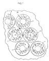
- FIG 7 is an enlarged view of a section of the cross section through a filter vessel (see Figure 4).
- Filter candles 1 are arranged like a honeycomb. In the course the alluvium with filter aid and filtration An Anschwemm harsh A forms on the candle wall 10 Filter aid. Rubbers are deposited in the course of filtration to the precoat, so that the precoat A in the course of time due to the turbidities and due to in the unfiltered material added to the filter aid increases. The filtration is continued until the filter layer a having maximum diameter 2a. The maximum diameter 2a is in the inventive embodiment 70 mm. Thereby results between the precoat layers A of two adjacent Filter candles at a distance m of 72 mm, a gap s of 2 mm. This gap is provided as a safety distance so that the precoat layers A of adjacent filter cartridges are not touch, resulting in uneven pressure conditions and thus Can cause bending of the candle.
- FIG. 8 schematically shows a mandrel 30 on which support rods 2 be attached.
- support rods 2 For producing a candle wall 10 of an inventive Filter candle are supporting rods 2 on this mandrel 30 fixed in recesses 31.
- the wire (not shown in Figure 8) helically wound on the support rods 2 and with welded this. So that the diameter of the filter candle according to the invention can be reduced, have the support rods 22nd (see also Figure 3) a rounding at its radially inner At the end of 12 Thanks to the rounding it is avoided that the inner Ends of the support rods 2 too small for small candle diameters lie together.
Landscapes
- Chemical & Material Sciences (AREA)
- Chemical Kinetics & Catalysis (AREA)
- Filtration Of Liquid (AREA)
- Filtering Materials (AREA)
- Filtering Of Dispersed Particles In Gases (AREA)
Priority Applications (5)
| Application Number | Priority Date | Filing Date | Title |
|---|---|---|---|
| DE50209971T DE50209971D1 (de) | 2002-07-08 | 2002-07-08 | Anschwemmfilterkerze, Anschwemmfilter und Verwendung einer Filterkerze |
| AT02015171T ATE359853T1 (de) | 2002-07-08 | 2002-07-08 | Anschwemmfilterkerze, anschwemmfilter und verwendung einer filterkerze |
| EP02015171A EP1380332B1 (fr) | 2002-07-08 | 2002-07-08 | Bougie de filtration pour filtre à pré-couche, Filtre à pré-couche et utilisation d' une bougie de filtration |
| US10/614,692 US20040065627A1 (en) | 2002-07-08 | 2003-07-08 | Precoat filter cartridge, precoat cartridge filter and use of a filter cartridge |
| JP2003272040A JP2004034029A (ja) | 2002-07-08 | 2003-07-08 | プレコートフィルタカートリッジ、プレコートカートリッジフィルタ及びフィルタカートリッジの使用方法 |
Applications Claiming Priority (1)
| Application Number | Priority Date | Filing Date | Title |
|---|---|---|---|
| EP02015171A EP1380332B1 (fr) | 2002-07-08 | 2002-07-08 | Bougie de filtration pour filtre à pré-couche, Filtre à pré-couche et utilisation d' une bougie de filtration |
Publications (2)
| Publication Number | Publication Date |
|---|---|
| EP1380332A1 true EP1380332A1 (fr) | 2004-01-14 |
| EP1380332B1 EP1380332B1 (fr) | 2007-04-18 |
Family
ID=29724404
Family Applications (1)
| Application Number | Title | Priority Date | Filing Date |
|---|---|---|---|
| EP02015171A Expired - Lifetime EP1380332B1 (fr) | 2002-07-08 | 2002-07-08 | Bougie de filtration pour filtre à pré-couche, Filtre à pré-couche et utilisation d' une bougie de filtration |
Country Status (5)
| Country | Link |
|---|---|
| US (1) | US20040065627A1 (fr) |
| EP (1) | EP1380332B1 (fr) |
| JP (1) | JP2004034029A (fr) |
| AT (1) | ATE359853T1 (fr) |
| DE (1) | DE50209971D1 (fr) |
Cited By (6)
| Publication number | Priority date | Publication date | Assignee | Title |
|---|---|---|---|---|
| WO2007107719A1 (fr) * | 2006-03-17 | 2007-09-27 | Fairey Industrial Ceramics Limited | Ensembles de traitement |
| WO2010115575A1 (fr) * | 2009-04-06 | 2010-10-14 | Krones Ag | Préparation de sauce au soja à l'aide d'un filtre-bougie à précouche |
| DE102011014184A1 (de) | 2011-03-16 | 2012-09-20 | Khs Gmbh | Vorrichtung und Verfahren zur Stabilisierung einer Flüssigkeit, insbesondere Bier |
| DE102015013978A1 (de) | 2015-10-29 | 2017-05-04 | Stabifix Brauerei-Technik KG | Verfahren zur Behandlung von Getränken |
| RU2661215C1 (ru) * | 2017-04-19 | 2018-07-13 | Федеральное государственное бюджетное образовательное учреждение высшего образования "Нижегородский государственный архитектурно-строительный университет" (ННГАСУ) | Намывная патронная фильтровальная установка для очистки воды |
| EP4218422A1 (fr) | 2022-02-01 | 2023-08-02 | KHS GmbH | Procédé et installation de traitement de boissons pour stabiliser des boissons |
Families Citing this family (6)
| Publication number | Priority date | Publication date | Assignee | Title |
|---|---|---|---|---|
| DE202005009390U1 (de) * | 2005-06-14 | 2006-10-19 | Mann + Hummel Gmbh | Filtermodul |
| JP5384211B2 (ja) | 2009-06-12 | 2014-01-08 | 株式会社日立産機システム | フィルター、及びそれを備えたインクジェット記録装置 |
| EP2407226A1 (fr) * | 2010-07-16 | 2012-01-18 | Filtrox AG | Module de filtration pour l'utilisation unique, ainsi que procédé de fabrication et d'utilisation d'un tel module de filtration |
| RU2469767C2 (ru) * | 2010-12-13 | 2012-12-20 | Федеральное государственное образовательное учреждение высшего профессионального образования "Казанский государственный архитектурно-строительный университет" (КазГАСУ) | Намывной патронный фильтр |
| JP5701358B2 (ja) * | 2013-10-02 | 2015-04-15 | 株式会社日立産機システム | フィルター、及びそれを備えたインクジェット記録装置 |
| US10406458B1 (en) * | 2018-03-23 | 2019-09-10 | Blue Skies Global LLC | Regenerative media filtration |
Citations (6)
| Publication number | Priority date | Publication date | Assignee | Title |
|---|---|---|---|---|
| US3253714A (en) * | 1963-10-01 | 1966-05-31 | Croll Reynolds Engineering Com | Pressure filter |
| US3503516A (en) * | 1968-09-05 | 1970-03-31 | Henry Mfg Co Inc | Pressure filter and tubular filter elements therefor |
| US4267039A (en) * | 1977-12-05 | 1981-05-12 | Ecodyne Corporation | Fluid filtration method and apparatus |
| EP0203206A1 (fr) * | 1985-05-02 | 1986-12-03 | Filtrox Maschinenbau A.-G. | Filtre à précouche lavable par reflux avec des bougies suspendues et utilisation d'un tube à fentes à cet effet |
| US4849103A (en) * | 1986-05-23 | 1989-07-18 | Hoechst Aktiengesellschaft | Filter apparatus for the uniform filtration of plastic melts |
| DE19518575A1 (de) * | 1995-05-20 | 1996-11-21 | Wabag Wassertechn Anlagen Gmbh | Vorrichtung und Verfahren zum Rückspülen von Kerzen- oder Anschwemmfiltern |
Family Cites Families (28)
| Publication number | Priority date | Publication date | Assignee | Title |
|---|---|---|---|---|
| US236416A (en) * | 1881-01-11 | William o | ||
| US235851A (en) * | 1880-12-28 | William o | ||
| DE2512781C3 (de) * | 1975-03-22 | 1978-09-14 | Boll & Kirch Filterbau Gmbh, 5000 Koeln | Filterkerze mit riickspülbare Filterapparate |
| US4028230A (en) * | 1975-04-02 | 1977-06-07 | Jesse Rosenblum | Vibratory separator screen and method of manufacture |
| GB1604062A (en) * | 1978-01-11 | 1981-12-02 | United Wire Group Ltd | Coverings for submersible or semi-submersible structures |
| US4224166A (en) * | 1978-07-11 | 1980-09-23 | Marshall And Williams Company | Drum filter and method |
| GB2055597B (en) * | 1979-08-09 | 1983-02-23 | Pa Management Consult | Vibratory screening apparatus for screening liquids |
| GB2085744B (en) * | 1980-10-20 | 1984-06-13 | Thule United Ltd | Vibratory screening apparatus |
| CA1208864A (fr) * | 1982-09-14 | 1986-08-05 | Andrew M. Bews | Revetement antisalissure pour bouees et balises flottantes de navigation maritime |
| GB8418658D0 (en) * | 1984-07-21 | 1984-08-22 | Thule United Ltd | Filtering screens |
| GB8514982D0 (en) * | 1985-06-13 | 1985-07-17 | Thule United Ltd | Screen clamping |
| GB8514983D0 (en) * | 1985-06-13 | 1985-07-17 | Thule United Ltd | Screen clamping |
| US5137622A (en) * | 1988-09-27 | 1992-08-11 | United Wire Limited | Filter screen assembly |
| US5084174A (en) * | 1990-10-23 | 1992-01-28 | Tamfelt Oy Ab | Filter bag for a machine screen |
| US5417858A (en) * | 1993-01-13 | 1995-05-23 | Derrick Manufacturing Corporation | Screen assembly for vibrating screening machine |
| EP0680385B1 (fr) * | 1993-01-13 | 1999-09-15 | Derrick Manufacturing Corporation | Crible pour cribleur a vibration et procede de fabrication d'un tel crible |
| US5958236A (en) * | 1993-01-13 | 1999-09-28 | Derrick Manufacturing Corporation | Undulating screen for vibratory screening machine and method of fabrication thereof |
| GB9309521D0 (en) * | 1993-05-08 | 1993-06-23 | United Wire Ltd | Improved method |
| GB9404071D0 (en) * | 1994-03-03 | 1994-04-20 | United Wire Ltd | Improved sifting screen |
| US5819952A (en) * | 1995-08-29 | 1998-10-13 | United Wire Limited | Sifting screen |
| US5921399A (en) * | 1996-06-07 | 1999-07-13 | Derrick Corporation | Gumbo separator |
| US5944197A (en) * | 1997-04-24 | 1999-08-31 | Southwestern Wire Cloth, Inc. | Rectangular opening woven screen mesh for filtering solid particles |
| US6439392B1 (en) * | 1997-09-02 | 2002-08-27 | Southwestern Wire Cloth, Inc. | Vibrating screen assembly with tubular frame |
| US5967336A (en) * | 1997-09-02 | 1999-10-19 | Southwestern Wire Cloth, Inc. | Vibrating screen assembly with improved frame |
| US5927511A (en) * | 1998-06-29 | 1999-07-27 | Southwestern Wire Cloth, Inc. | Flat screen panel for crowned deck vibrating shaker |
| US6491168B1 (en) * | 2000-04-23 | 2002-12-10 | J + L Fiber Services, Inc. | Pulp screen basket |
| US6431368B1 (en) * | 2000-07-05 | 2002-08-13 | Emerson Electric Co. | Vibratory screen |
| US6646022B2 (en) * | 2000-07-05 | 2003-11-11 | Mitsubishi Rayon Co., Ltd. | Photocuring resin compositions, photocuring sheets and molded article using the same, and processes of production thereof |
-
2002
- 2002-07-08 AT AT02015171T patent/ATE359853T1/de not_active IP Right Cessation
- 2002-07-08 DE DE50209971T patent/DE50209971D1/de not_active Expired - Lifetime
- 2002-07-08 EP EP02015171A patent/EP1380332B1/fr not_active Expired - Lifetime
-
2003
- 2003-07-08 JP JP2003272040A patent/JP2004034029A/ja active Pending
- 2003-07-08 US US10/614,692 patent/US20040065627A1/en not_active Abandoned
Patent Citations (6)
| Publication number | Priority date | Publication date | Assignee | Title |
|---|---|---|---|---|
| US3253714A (en) * | 1963-10-01 | 1966-05-31 | Croll Reynolds Engineering Com | Pressure filter |
| US3503516A (en) * | 1968-09-05 | 1970-03-31 | Henry Mfg Co Inc | Pressure filter and tubular filter elements therefor |
| US4267039A (en) * | 1977-12-05 | 1981-05-12 | Ecodyne Corporation | Fluid filtration method and apparatus |
| EP0203206A1 (fr) * | 1985-05-02 | 1986-12-03 | Filtrox Maschinenbau A.-G. | Filtre à précouche lavable par reflux avec des bougies suspendues et utilisation d'un tube à fentes à cet effet |
| US4849103A (en) * | 1986-05-23 | 1989-07-18 | Hoechst Aktiengesellschaft | Filter apparatus for the uniform filtration of plastic melts |
| DE19518575A1 (de) * | 1995-05-20 | 1996-11-21 | Wabag Wassertechn Anlagen Gmbh | Vorrichtung und Verfahren zum Rückspülen von Kerzen- oder Anschwemmfiltern |
Cited By (13)
| Publication number | Priority date | Publication date | Assignee | Title |
|---|---|---|---|---|
| WO2007107719A1 (fr) * | 2006-03-17 | 2007-09-27 | Fairey Industrial Ceramics Limited | Ensembles de traitement |
| GB2436076B (en) * | 2006-03-17 | 2011-07-13 | Fairey Ceramics | Fluid treatment assemblies |
| US8128823B2 (en) | 2006-03-17 | 2012-03-06 | Fairey Industrial Ceramics Limited | Treatment assemblies |
| WO2010115575A1 (fr) * | 2009-04-06 | 2010-10-14 | Krones Ag | Préparation de sauce au soja à l'aide d'un filtre-bougie à précouche |
| CN102427737A (zh) * | 2009-04-06 | 2012-04-25 | 克朗斯股份公司 | 借助于棒式预涂过滤器生产酱油的方法 |
| WO2012123059A1 (fr) | 2011-03-16 | 2012-09-20 | Khs Gmbh | Dispositif et procédé servant à stabiliser un liquide, en particulier de la bière |
| DE102011014184A1 (de) | 2011-03-16 | 2012-09-20 | Khs Gmbh | Vorrichtung und Verfahren zur Stabilisierung einer Flüssigkeit, insbesondere Bier |
| EP2686413B1 (fr) | 2011-03-16 | 2016-12-28 | KHS GmbH | Dispositif et procédé servant à stabiliser un liquide, en particulier de la bière |
| US9540603B2 (en) | 2011-03-16 | 2017-01-10 | Khs Gmbh | Apparatus and process for stabilizing a liquid, in particular beer |
| DE102015013978A1 (de) | 2015-10-29 | 2017-05-04 | Stabifix Brauerei-Technik KG | Verfahren zur Behandlung von Getränken |
| RU2661215C1 (ru) * | 2017-04-19 | 2018-07-13 | Федеральное государственное бюджетное образовательное учреждение высшего образования "Нижегородский государственный архитектурно-строительный университет" (ННГАСУ) | Намывная патронная фильтровальная установка для очистки воды |
| EP4218422A1 (fr) | 2022-02-01 | 2023-08-02 | KHS GmbH | Procédé et installation de traitement de boissons pour stabiliser des boissons |
| DE102022102235A1 (de) | 2022-02-01 | 2023-08-03 | Khs Gmbh | Verfahren und Getränkebehandlungsanlage zur Stabilisierung von Getränken |
Also Published As
| Publication number | Publication date |
|---|---|
| EP1380332B1 (fr) | 2007-04-18 |
| ATE359853T1 (de) | 2007-05-15 |
| JP2004034029A (ja) | 2004-02-05 |
| US20040065627A1 (en) | 2004-04-08 |
| DE50209971D1 (de) | 2007-05-31 |
Similar Documents
| Publication | Publication Date | Title |
|---|---|---|
| DE19745381B4 (de) | Filtermedium zur Feststoff-Flüssigkeitstrennung insbesondere für flüssige Abfallstoffe, Abwasser usw. | |
| DE3943249C2 (de) | Geschlossenes Filterelement | |
| EP0824033B1 (fr) | Cartouche filtrant avec tamis dans un orifice de sortie | |
| EP1380332B1 (fr) | Bougie de filtration pour filtre à pré-couche, Filtre à pré-couche et utilisation d' une bougie de filtration | |
| EP0968039B1 (fr) | Dispositif de filtration avec lavage a contre-courant | |
| WO1993023139A1 (fr) | Dispositif de filtrage | |
| DE2910053A1 (de) | Filtriervorrichtung | |
| EP1144069B1 (fr) | Element filtre a bougies | |
| EP0810019B1 (fr) | Bougie filtrante à arêtes pour la filtration à précouche, son procédé de fabrication et pièce d'extrémité pour la bougie filtrante à arêtes pour la filtration à précouche | |
| EP1243302B1 (fr) | Bougie filtrante | |
| EP1510503B1 (fr) | Appareil de filtration d'eau et cartouche filtrante avec rainure | |
| EP1243303B1 (fr) | Bougie filtrante | |
| EP3165269A1 (fr) | Filtre à eau conçu comme un embout d'écoulement | |
| EP0203206B1 (fr) | Filtre à précouche lavable par reflux avec des bougies suspendues et utilisation d'un tube à fentes à cet effet | |
| DE3238783A1 (de) | Filterkerze | |
| DE1943999B2 (de) | Vorrichtung zum filtrieren einer fluessigkeit | |
| DE10038412A1 (de) | Filterelement mit einem auf einen Stützkörper aufgebrachten Filtermedium | |
| DE1536826B2 (de) | Filtervorrichtung | |
| DE10244292B4 (de) | Verwendung von Filterelementen in Rückspülfiltern | |
| EP1000647B1 (fr) | Filtre à bougie pour la filtration à précouche de boissons | |
| DE102019007000B4 (de) | Filtervorrichtung | |
| DE9300755U1 (de) | Siebförmige Drainageelemente | |
| DE1611077C (de) | Profilierter Haltestab zum Aufnehmen von kreisförmigen Spaltfilterelementen | |
| EP0071200B1 (fr) | Récipient de filtration, notamment pour des piscines | |
| DE29908293U1 (de) | Flüssigkeitsfilter |
Legal Events
| Date | Code | Title | Description |
|---|---|---|---|
| PUAI | Public reference made under article 153(3) epc to a published international application that has entered the european phase |
Free format text: ORIGINAL CODE: 0009012 |
|
| AK | Designated contracting states |
Kind code of ref document: A1 Designated state(s): AT BE BG CH CY CZ DE DK EE ES FI FR GB GR IE IT LI LU MC NL PT SE SK TR |
|
| AX | Request for extension of the european patent |
Extension state: AL LT LV MK RO SI |
|
| 17P | Request for examination filed |
Effective date: 20040429 |
|
| AKX | Designation fees paid |
Designated state(s): AT BE BG CH CY CZ DE DK EE ES FI FR GB GR IE IT LI LU MC NL PT SE SK TR |
|
| 17Q | First examination report despatched |
Effective date: 20041207 |
|
| GRAP | Despatch of communication of intention to grant a patent |
Free format text: ORIGINAL CODE: EPIDOSNIGR1 |
|
| GRAS | Grant fee paid |
Free format text: ORIGINAL CODE: EPIDOSNIGR3 |
|
| GRAA | (expected) grant |
Free format text: ORIGINAL CODE: 0009210 |
|
| AK | Designated contracting states |
Kind code of ref document: B1 Designated state(s): AT BE BG CH CY CZ DE DK EE ES FI FR GB GR IE IT LI LU MC NL PT SE SK TR |
|
| PG25 | Lapsed in a contracting state [announced via postgrant information from national office to epo] |
Ref country code: FI Free format text: LAPSE BECAUSE OF FAILURE TO SUBMIT A TRANSLATION OF THE DESCRIPTION OR TO PAY THE FEE WITHIN THE PRESCRIBED TIME-LIMIT Effective date: 20070418 |
|
| REG | Reference to a national code |
Ref country code: CH Ref legal event code: EP |
|
| REG | Reference to a national code |
Ref country code: IE Ref legal event code: FG4D Free format text: LANGUAGE OF EP DOCUMENT: GERMAN |
|
| REF | Corresponds to: |
Ref document number: 50209971 Country of ref document: DE Date of ref document: 20070531 Kind code of ref document: P |
|
| REG | Reference to a national code |
Ref country code: CH Ref legal event code: NV Representative=s name: HEPP, WENGER & RYFFEL AG |
|
| PG25 | Lapsed in a contracting state [announced via postgrant information from national office to epo] |
Ref country code: SE Free format text: LAPSE BECAUSE OF FAILURE TO SUBMIT A TRANSLATION OF THE DESCRIPTION OR TO PAY THE FEE WITHIN THE PRESCRIBED TIME-LIMIT Effective date: 20070718 |
|
| PG25 | Lapsed in a contracting state [announced via postgrant information from national office to epo] |
Ref country code: ES Free format text: LAPSE BECAUSE OF FAILURE TO SUBMIT A TRANSLATION OF THE DESCRIPTION OR TO PAY THE FEE WITHIN THE PRESCRIBED TIME-LIMIT Effective date: 20070729 |
|
| PG25 | Lapsed in a contracting state [announced via postgrant information from national office to epo] |
Ref country code: PT Free format text: LAPSE BECAUSE OF FAILURE TO SUBMIT A TRANSLATION OF THE DESCRIPTION OR TO PAY THE FEE WITHIN THE PRESCRIBED TIME-LIMIT Effective date: 20070918 |
|
| NLV1 | Nl: lapsed or annulled due to failure to fulfill the requirements of art. 29p and 29m of the patents act | ||
| GBV | Gb: ep patent (uk) treated as always having been void in accordance with gb section 77(7)/1977 [no translation filed] |
Effective date: 20070418 |
|
| REG | Reference to a national code |
Ref country code: IE Ref legal event code: FD4D |
|
| EN | Fr: translation not filed | ||
| BERE | Be: lapsed |
Owner name: FILTROX A.G. Effective date: 20070731 |
|
| PG25 | Lapsed in a contracting state [announced via postgrant information from national office to epo] |
Ref country code: BG Free format text: LAPSE BECAUSE OF FAILURE TO SUBMIT A TRANSLATION OF THE DESCRIPTION OR TO PAY THE FEE WITHIN THE PRESCRIBED TIME-LIMIT Effective date: 20070718 Ref country code: DK Free format text: LAPSE BECAUSE OF FAILURE TO SUBMIT A TRANSLATION OF THE DESCRIPTION OR TO PAY THE FEE WITHIN THE PRESCRIBED TIME-LIMIT Effective date: 20070418 Ref country code: CZ Free format text: LAPSE BECAUSE OF FAILURE TO SUBMIT A TRANSLATION OF THE DESCRIPTION OR TO PAY THE FEE WITHIN THE PRESCRIBED TIME-LIMIT Effective date: 20070418 Ref country code: IE Free format text: LAPSE BECAUSE OF FAILURE TO SUBMIT A TRANSLATION OF THE DESCRIPTION OR TO PAY THE FEE WITHIN THE PRESCRIBED TIME-LIMIT Effective date: 20070418 Ref country code: NL Free format text: LAPSE BECAUSE OF FAILURE TO SUBMIT A TRANSLATION OF THE DESCRIPTION OR TO PAY THE FEE WITHIN THE PRESCRIBED TIME-LIMIT Effective date: 20070418 |
|
| PLBE | No opposition filed within time limit |
Free format text: ORIGINAL CODE: 0009261 |
|
| STAA | Information on the status of an ep patent application or granted ep patent |
Free format text: STATUS: NO OPPOSITION FILED WITHIN TIME LIMIT |
|
| PG25 | Lapsed in a contracting state [announced via postgrant information from national office to epo] |
Ref country code: SK Free format text: LAPSE BECAUSE OF FAILURE TO SUBMIT A TRANSLATION OF THE DESCRIPTION OR TO PAY THE FEE WITHIN THE PRESCRIBED TIME-LIMIT Effective date: 20070418 |
|
| 26N | No opposition filed |
Effective date: 20080121 |
|
| PG25 | Lapsed in a contracting state [announced via postgrant information from national office to epo] |
Ref country code: MC Free format text: LAPSE BECAUSE OF NON-PAYMENT OF DUE FEES Effective date: 20070731 Ref country code: FR Free format text: LAPSE BECAUSE OF FAILURE TO SUBMIT A TRANSLATION OF THE DESCRIPTION OR TO PAY THE FEE WITHIN THE PRESCRIBED TIME-LIMIT Effective date: 20071214 Ref country code: GB Free format text: LAPSE BECAUSE OF FAILURE TO SUBMIT A TRANSLATION OF THE DESCRIPTION OR TO PAY THE FEE WITHIN THE PRESCRIBED TIME-LIMIT Effective date: 20070418 Ref country code: GR Free format text: LAPSE BECAUSE OF FAILURE TO SUBMIT A TRANSLATION OF THE DESCRIPTION OR TO PAY THE FEE WITHIN THE PRESCRIBED TIME-LIMIT Effective date: 20070719 Ref country code: IT Free format text: LAPSE BECAUSE OF FAILURE TO SUBMIT A TRANSLATION OF THE DESCRIPTION OR TO PAY THE FEE WITHIN THE PRESCRIBED TIME-LIMIT Effective date: 20070418 |
|
| PG25 | Lapsed in a contracting state [announced via postgrant information from national office to epo] |
Ref country code: BE Free format text: LAPSE BECAUSE OF NON-PAYMENT OF DUE FEES Effective date: 20070731 |
|
| PG25 | Lapsed in a contracting state [announced via postgrant information from national office to epo] |
Ref country code: FR Free format text: LAPSE BECAUSE OF FAILURE TO SUBMIT A TRANSLATION OF THE DESCRIPTION OR TO PAY THE FEE WITHIN THE PRESCRIBED TIME-LIMIT Effective date: 20070418 Ref country code: AT Free format text: LAPSE BECAUSE OF NON-PAYMENT OF DUE FEES Effective date: 20070708 |
|
| PG25 | Lapsed in a contracting state [announced via postgrant information from national office to epo] |
Ref country code: EE Free format text: LAPSE BECAUSE OF FAILURE TO SUBMIT A TRANSLATION OF THE DESCRIPTION OR TO PAY THE FEE WITHIN THE PRESCRIBED TIME-LIMIT Effective date: 20070418 |
|
| PG25 | Lapsed in a contracting state [announced via postgrant information from national office to epo] |
Ref country code: CY Free format text: LAPSE BECAUSE OF FAILURE TO SUBMIT A TRANSLATION OF THE DESCRIPTION OR TO PAY THE FEE WITHIN THE PRESCRIBED TIME-LIMIT Effective date: 20070418 |
|
| PG25 | Lapsed in a contracting state [announced via postgrant information from national office to epo] |
Ref country code: LU Free format text: LAPSE BECAUSE OF NON-PAYMENT OF DUE FEES Effective date: 20070708 |
|
| PG25 | Lapsed in a contracting state [announced via postgrant information from national office to epo] |
Ref country code: TR Free format text: LAPSE BECAUSE OF FAILURE TO SUBMIT A TRANSLATION OF THE DESCRIPTION OR TO PAY THE FEE WITHIN THE PRESCRIBED TIME-LIMIT Effective date: 20070418 |
|
| REG | Reference to a national code |
Ref country code: CH Ref legal event code: PUE Owner name: FILTROX ENGINEERING AG, CH Free format text: FORMER OWNER: FILTROX AG, CH |
|
| REG | Reference to a national code |
Ref country code: DE Ref legal event code: R082 Ref document number: 50209971 Country of ref document: DE Representative=s name: ISARPATENT GBR PATENT- UND RECHTSANWAELTE, DE Effective date: 20121122 Ref country code: DE Ref legal event code: R081 Ref document number: 50209971 Country of ref document: DE Owner name: FILTROX ENGINEERING AG, CH Free format text: FORMER OWNER: FILTROX AG, 9001 ST. GALLEN, CH Effective date: 20121122 Ref country code: DE Ref legal event code: R081 Ref document number: 50209971 Country of ref document: DE Owner name: BUCHER UNIPEKTIN AG, CH Free format text: FORMER OWNER: FILTROX AG, 9001 ST. GALLEN, CH Effective date: 20121122 Ref country code: DE Ref legal event code: R082 Ref document number: 50209971 Country of ref document: DE Representative=s name: ISARPATENT PATENTANWAELTE BEHNISCH, BARTH, CHA, DE Effective date: 20121122 Ref country code: DE Ref legal event code: R082 Ref document number: 50209971 Country of ref document: DE Representative=s name: ISARPATENT - PATENTANWAELTE- UND RECHTSANWAELT, DE Effective date: 20121122 |
|
| REG | Reference to a national code |
Ref country code: CH Ref legal event code: PUE Owner name: BUCHER UNIPEKTIN AG, CH Free format text: FORMER OWNER: FILTROX ENGINEERING AG, CH |
|
| REG | Reference to a national code |
Ref country code: DE Ref legal event code: R082 Ref document number: 50209971 Country of ref document: DE Representative=s name: ISARPATENT - PATENT- UND RECHTSANWAELTE BEHNIS, DE Ref country code: DE Ref legal event code: R082 Ref document number: 50209971 Country of ref document: DE Representative=s name: ISARPATENT - PATENTANWAELTE- UND RECHTSANWAELT, DE Ref country code: DE Ref legal event code: R081 Ref document number: 50209971 Country of ref document: DE Owner name: BUCHER UNIPEKTIN AG, CH Free format text: FORMER OWNER: FILTROX ENGINEERING AG, ST. GALLEN, CH Ref country code: DE Ref legal event code: R082 Ref document number: 50209971 Country of ref document: DE Representative=s name: ISARPATENT - PATENT- UND RECHTSANWAELTE BARTH , DE |
|
| PGFP | Annual fee paid to national office [announced via postgrant information from national office to epo] |
Ref country code: CH Payment date: 20210721 Year of fee payment: 20 Ref country code: DE Payment date: 20210721 Year of fee payment: 20 |
|
| REG | Reference to a national code |
Ref country code: DE Ref legal event code: R071 Ref document number: 50209971 Country of ref document: DE |
|
| REG | Reference to a national code |
Ref country code: CH Ref legal event code: PL |