EP1380245A1 - Floor cleaning device - Google Patents
Floor cleaning device Download PDFInfo
- Publication number
- EP1380245A1 EP1380245A1 EP20030013519 EP03013519A EP1380245A1 EP 1380245 A1 EP1380245 A1 EP 1380245A1 EP 20030013519 EP20030013519 EP 20030013519 EP 03013519 A EP03013519 A EP 03013519A EP 1380245 A1 EP1380245 A1 EP 1380245A1
- Authority
- EP
- European Patent Office
- Prior art keywords
- cleaning device
- floor cleaning
- support
- dirt
- floor
- Prior art date
- Legal status (The legal status is an assumption and is not a legal conclusion. Google has not performed a legal analysis and makes no representation as to the accuracy of the status listed.)
- Withdrawn
Links
Images

Classifications
-
- A—HUMAN NECESSITIES
- A47—FURNITURE; DOMESTIC ARTICLES OR APPLIANCES; COFFEE MILLS; SPICE MILLS; SUCTION CLEANERS IN GENERAL
- A47L—DOMESTIC WASHING OR CLEANING; SUCTION CLEANERS IN GENERAL
- A47L9/00—Details or accessories of suction cleaners, e.g. mechanical means for controlling the suction or for effecting pulsating action; Storing devices specially adapted to suction cleaners or parts thereof; Carrying-vehicles specially adapted for suction cleaners
- A47L9/009—Carrying-vehicles; Arrangements of trollies or wheels; Means for avoiding mechanical obstacles
-
- A—HUMAN NECESSITIES
- A47—FURNITURE; DOMESTIC ARTICLES OR APPLIANCES; COFFEE MILLS; SPICE MILLS; SUCTION CLEANERS IN GENERAL
- A47L—DOMESTIC WASHING OR CLEANING; SUCTION CLEANERS IN GENERAL
- A47L2201/00—Robotic cleaning machines, i.e. with automatic control of the travelling movement or the cleaning operation
Definitions
- the invention relates to a floor cleaning device with a dirt inlet opening having housing and a dirt collecting container as well with a device for collecting dirt from a floor surface to be cleaned and for transferring the dirt into the dirt collecting container, wherein at least one support element is held on the housing for support of the housing on the bottom surface.
- Such floor cleaning devices come in the form of sweepers or Vacuum cleaners for use. This is done, for example, with the help of a sweeping brush and / or dirt is picked up from the bottom surface by means of a suction stream and transferred to the dirt collector.
- the housing will guided along the bottom surface, it being by means of a support element, for example, a support roller, is supported on the bottom surface.
- the object of the present invention is to provide a floor cleaning device at the outset mentioned type in such a way that there is a more uniform cleaning result allows.
- This task is carried out in a floor cleaning device of the generic type solved according to the invention in that the support element about an axis of rotation rotatably mounted support disc which has a radially outer Has contact area for contact with the floor surface and first and second Side flanks comprises, at least one side flank oblique to the axis of rotation is aligned.
- the cleaning result from The distance between the dirt inlet opening and the floor surface depends. This distance is used when cleaning carpets by the Carpet fibers affected.
- the support disc with at least a side flank aligned obliquely to the axis of rotation can Carpet fibers when moving the floor cleaning device along the one to be cleaned
- Floor surface oblique to the direction of movement of the floor cleaning device be pressed outwards so that the contact area of the support disc only moved up and down to a small extent perpendicular to the floor surface and consequently the dirt inlet opening practically a constant distance to the floor surface, so that a uniform cleaning result can be achieved.
- both the first and the second side flank are aligned obliquely to the axis of rotation.
- first and the second Side flanks in their immediately adjacent to the contact area of the support disc End area are aligned obliquely to each other.
- the support disc at least in its adjacent to the contact area Area in cross section is substantially V-shaped, so that carpet fibers related to a main direction of movement of the floor cleaning device can be pushed outwards on both sides.
- a relatively high specific surface pressure can be achieved, so that even with floor cleaning devices with a light weight a rocking or rocking motion cleaning carpets and especially when moving from one Hard surface to a carpet can be reliably avoided.
- first and / or second side flanks at an angle of about 60 ° to about 80 ° of the support disc aligned.
- the side flanks can at least in sections just be designed.
- first and / or second side flanks are convex.
- a particularly high specific surface pressure and therefore a constant one Sinking of the floor cleaning device in the area of the support element in the Carpeting can be achieved in that the contact area of the support disc is convex.
- the support element has two support disks, the are rigidly connected.
- the support element is designed as a double disc, each disc at least has a side flank oriented obliquely to the axis of rotation.
- the mutually facing Side flanks of the two support disks aligned obliquely to each other are, their mutual distance increases in the radial direction.
- the side flanks facing each other define one between them Gap, for example, a substantially V-shaped configuration can have.
- Floor cleaning device is characterized in that the two Support discs are integrally connected.
- the support disks can for example, be made of a plastic material, manufactured in particular through an injection molding process.
- the floor cleaning device is two in line and has spaced-apart support elements, which are preferred are each designed as a double disc.
- the two support elements can be arranged on both sides of a longitudinal axis of the floor cleaning device be, they are preferably positioned mirror-symmetrically to the longitudinal axis.
- the at least one support element on Edge of the dirt inlet opening of the floor cleaning device is arranged.
- the housing of the floor cleaning device is consequently in the area of the dirt inlet opening supported so that this when moving the floor cleaning device maintains an even distance from the floor surface.
- the Floor cleaning device is designed to be self-propelled and comprises a chassis, on which at least two drive wheels are mounted, which have an electrical Drive unit are coupled, and that the at least one support element is arranged between the dirt inlet opening and the drive wheels.
- the at least one support element is arranged between the dirt inlet opening and the drive wheels.
- two support elements are used, which are related to the on the main direction of movement of the floor cleaner Edge of the dirt inlet opening are stored.
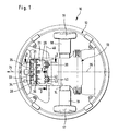
- an overall reference number 10 self-propelled and self-steering floor cleaning device shown schematically. It comprises a housing 12 which forms a chassis 13 and one Has base plate 14 and a not shown in the drawing, per se known housing cover, which can be placed on the top of the housing 12 is.
- a housing 12 which forms a chassis 13 and one Has base plate 14 and a not shown in the drawing, per se known housing cover, which can be placed on the top of the housing 12 is.
- two drive wheels 16, 17 are rotatably mounted, which an electric drive motor 18 or 19 is assigned.
- the drive motors 18, 19 are held on the chassis 13 and stand up with one the top of the chassis 13 arranged, known and therefore drive electronics not shown in the drawing and also with the top of the chassis 13 arranged, known batteries in electrical connection.
- a dirt inlet opening 21 is formed, which, related to a main direction of movement 24 of the floor cleaning device 10, a front edge 28 oriented transversely to its longitudinal axis 26, a rear edge 29, and side edges 30 and 31. Adjacent to the leading edge 28 and aligned parallel to it at the dirt inlet opening 21 a known and therefore shown only schematically in the drawing Brush roller 33 rotatably held, one on top of the bottom plate 14 arranged, known per se and therefore in the drawing Drive motor, not shown, is assigned.
- the brush roller 33 has a plurality of radially aligned brushes 34, which are connected to a shaft 35 are fixed and with their free ends down over the dirt inlet opening 21 survive.
- the chassis 13 On its upper side, the chassis 13 carries in known and therefore in the drawing, also not shown, a suction unit and Housing 12 receives a dirt collection container.
- a suction flow can start from the dirt inlet opening 21
- Direction of the dirt container are generated, so that from one cleaning floor surface, for example from a carpet 37, as in Figures 2 and 3 is shown, brushed dirt and in the dirt collector can be transferred.
- support elements 39, 40 rotatably held, which refer to the Longitudinal axis 26 arranged mirror-symmetrically to one another and configured identically are.
- the structure of the support elements 39 and 40 is in particular from Figure 3 clearly. They are each designed as a double disc and include for this purpose two support disks 42, 43 which are integrally connected to one another and in the illustrated embodiment have a common hub 44, which is rotatable about an axis of rotation 46 on a fixed to the base plate 14 Bearing axis 45 is held and two at a distance from each other plate-shaped support rings 47 and 48 protrude radially outwards, each are integrally connected to the hub 44.
- the support disks 42 and 43 have each have a jacket-shaped, convex contact area 49 or 50, with which the support rings 47 and 48 on the carpet 37th roll.
- the support disk 42 is one of the Support disc 43 facing away from the first side flank 51 and one of the support disc 43 facing second side flank 52.
- the second side flank 52 is aligned obliquely to the axis of rotation 46 and essentially flat designed.
- the first side flank 51 is stepped and has in its radially outer area one mirror-symmetrical to the second Side flank 52 aligned end portion 54 in combination with the contact area 49 and the radially outer end area of the second Side flank 52 of the support disk 42 is essentially a cross-section V-shaped design gives.
- a recess 55 connects to the end section 54 radially inward, the inner section aligned parallel to the second side flank 52 56 is connected to the hub 44.
- the support disc 43 is mirror-symmetrical to the support disc 42 and also includes first and second side flanks 58 and 59, respectively Side flank 58 is formed substantially flat, while the side flank 59 has a stepped course corresponding to the first side flank 51.
Abstract
Description
Die Erfindung betrifft ein Bodenreinigungsgerät mit einem eine Schmutzeintrittsöffnung aufweisenden Gehäuse und einem Schmutzsammelbehälter sowie mit einer Einrichtung zur Aufnahme von Schmutz von einer zu reinigenden Bodenfläche und zum Überführen des Schmutzes in den Schmutzsammelbehälter, wobei am Gehäuse mindestens ein Stützelement gehalten ist zum Abstützen des Gehäuses an der Bodenfläche.The invention relates to a floor cleaning device with a dirt inlet opening having housing and a dirt collecting container as well with a device for collecting dirt from a floor surface to be cleaned and for transferring the dirt into the dirt collecting container, wherein at least one support element is held on the housing for support of the housing on the bottom surface.
Derartige Bodenreinigungsgeräte kommen in Form von Kehrmaschinen oder Staubsaugern zum Einsatz. Hierzu wird beispielsweise mit Hilfe einer Kehrbürste und/oder mittels eines Saugstromes von der Bodenfläche Schmutz aufgenommen und in den Schmutzsammelbehälter überführt. Das Gehäuse wird entlang der Bodenfläche geführt, wobei es sich mittels eines Stützelements, beispielsweise einer Stützrolle, an der Bodenfläche abstützt.Such floor cleaning devices come in the form of sweepers or Vacuum cleaners for use. This is done, for example, with the help of a sweeping brush and / or dirt is picked up from the bottom surface by means of a suction stream and transferred to the dirt collector. The housing will guided along the bottom surface, it being by means of a support element, for example, a support roller, is supported on the bottom surface.
Insbesondere bei Bodenreinigungsgeräten, bei denen die Bodenfläche vom Gehäuse nur mit einem verhältnismäßig geringen Gewicht belastet wird, kann mittels bekannter Bodenreinigungsgeräte nicht in allen Fällen ein gleichbleibendes Reinigungsergebnis erzielt werden.Especially with floor cleaning devices, in which the floor area from Housing can only be loaded with a relatively low weight not a constant in all cases using known floor cleaning devices Cleaning result can be achieved.
Aufgabe der vorliegenden Erfindung ist es, ein Bodenreinigungsgerät der eingangs genannten Art derart weiterzubilden, daß es ein gleichmäßigeres Reinigungsergebnis ermöglicht.The object of the present invention is to provide a floor cleaning device at the outset mentioned type in such a way that there is a more uniform cleaning result allows.
Diese Aufgabe wird bei einem Bodenreinigungsgerät der gattungsgemäßen Art erfindungsgemäß dadurch gelöst, daß das Stützelement eine um eine Drehachse drehbar gelagerte Stützscheibe umfaßt, die einen radial außen liegenden Anlagebereich zur Anlage an die Bodenfläche aufweist und erste und zweite Seitenflanken umfaßt, wobei zumindest eine Seitenflanke schräg zur Drehachse ausgerichtet ist.This task is carried out in a floor cleaning device of the generic type solved according to the invention in that the support element about an axis of rotation rotatably mounted support disc which has a radially outer Has contact area for contact with the floor surface and first and second Side flanks comprises, at least one side flank oblique to the axis of rotation is aligned.
In die Erfindung fließt der Gedanke mit ein, daß das Reinigungsergebnis vom Abstand abhängig ist, den die Schmutzeintrittsöffnung zur Bodenfläche einnimmt. Dieser Abstand wird bei der Reinigung von Teppichböden durch die Teppichfasern beeinflußt. Durch die Ausgestaltung der Stützscheibe mit zumindest einer schräg zur Drehachse ausgerichteten Seitenflanke können die Teppichfasern beim Verfahren des Bodenreinigungsgeräts entlang der zu reinigenden Bodenfläche schräg zur Bewegungsrichtung des Bodenreinigungsgeräts nach außen gedrückt werden, so daß sich der Anlagebereich der Stützscheibe nur in geringem Umfang senkrecht zur Bodenfläche auf- und abbewegt und folglich die Schmutzeintrittsöffnung praktisch einen gleichbleibenden Abstand zur Bodenfläche einnimmt, so daß ein gleichmäßiges Reinigungsergebnis erzielt werden kann.The idea flows into the invention that the cleaning result from The distance between the dirt inlet opening and the floor surface depends. This distance is used when cleaning carpets by the Carpet fibers affected. By designing the support disc with at least a side flank aligned obliquely to the axis of rotation can Carpet fibers when moving the floor cleaning device along the one to be cleaned Floor surface oblique to the direction of movement of the floor cleaning device be pressed outwards so that the contact area of the support disc only moved up and down to a small extent perpendicular to the floor surface and consequently the dirt inlet opening practically a constant distance to the floor surface, so that a uniform cleaning result can be achieved.
Von Vorteil ist es, wenn sowohl die erste als auch die zweite Seitenflanke schräg zur Drehachse ausgerichtet sind.It is advantageous if both the first and the second side flank are aligned obliquely to the axis of rotation.
Als besonders günstig hat es sich erwiesen, wenn die ersten und die zweiten Seitenflanken in ihrem dem Anlagebereich der Stützscheibe unmittelbar benachbarten Endbereich schräg zueinander ausgerichtet sind. Dies hat zur Folge, daß die Stützscheibe zumindest in ihrer dem Anlagebereich benachbarten Bereich im Querschnitt im wesentlichen V-förmig ausgebildet ist, so daß Teppichfasern bezogen auf eine Hauptbewegungsrichtung des Bodenreinigungsgeräts beidseitig nach außen gedrückt werden können. Außerdem kann aufgrund einer derartigen Ausgestaltung der Stützscheibe ein verhältnismäßig hoher spezifischer Flächendruck erzielt werden, so daß selbst bei Bodenreinigungsgeräten mit geringem Gewicht eine Wipp- oder Schaukelbewegung bei der Reinigung von Teppichböden und insbesondere beim Übergang von einer Hartfläche zu einem Teppichboden zuverlässig vermieden werden kann.It has proven to be particularly favorable if the first and the second Side flanks in their immediately adjacent to the contact area of the support disc End area are aligned obliquely to each other. As a consequence, that the support disc at least in its adjacent to the contact area Area in cross section is substantially V-shaped, so that carpet fibers related to a main direction of movement of the floor cleaning device can be pushed outwards on both sides. In addition, due to such a configuration of the support disc a relatively high specific surface pressure can be achieved, so that even with floor cleaning devices with a light weight a rocking or rocking motion cleaning carpets and especially when moving from one Hard surface to a carpet can be reliably avoided.
Bei einer konstruktiv einfachen Ausführungsform sind die ersten und/oder zweiten Seitenflanken in einem Winkel von etwa 60° bis ca. 80° der Stützscheibe ausgerichtet. Die Seitenflanken können hierbei zumindest abschnittsweise eben ausgestaltet sein.In a structurally simple embodiment, the first and / or second side flanks at an angle of about 60 ° to about 80 ° of the support disc aligned. The side flanks can at least in sections just be designed.
Bei einer bevorzugten Ausführungsform ist vorgesehen, daß die ersten und/oder zweiten Seitenflanken konvex ausgebildet sind.In a preferred embodiment it is provided that the first and / or second side flanks are convex.
Ein besonders hoher spezifischer Flächendruck und damit ein gleichbleibendes Einsinken des Bodenreinigungsgeräts im Bereich des Stützelementes in den Teppichboden kann dadurch erzielt werden, daß der Anlagebereich der Stützscheibe konvex ausgestaltet ist.A particularly high specific surface pressure and therefore a constant one Sinking of the floor cleaning device in the area of the support element in the Carpeting can be achieved in that the contact area of the support disc is convex.
Bei einer besonders bevorzugten Ausführungsform des erfindungsgemäßen Bodenreinigungsgeräts weist das Stützelement zwei Stützscheiben auf, die starr miteinander verbunden sind. Bei einer derartigen Ausführungsform ist das Stützelement als Doppelscheibe ausgebildet, wobei jede Scheibe zumindest eine schräg zur Drehachse ausgerichtete Seitenflanke aufweist.In a particularly preferred embodiment of the invention Floor cleaning device, the support element has two support disks, the are rigidly connected. In such an embodiment the support element is designed as a double disc, each disc at least has a side flank oriented obliquely to the axis of rotation.
Von Vorteil ist es hierbei, wenn die einander zugewandten Seitenflanken der beiden Stützscheiben schräg zur Drehachse ausgerichtet sind. It is advantageous here if the mutually facing side flanks of the two support disks are aligned at an angle to the axis of rotation.
Bei einer vorteilhaften Ausführungsform ist vorgesehen, daß die einander zugewandten Seitenflanken der beiden Stützscheiben schräg zueinander ausgerichtet sind, wobei sich ihr gegenseitiger Abstand in radialer Richtung vergrößert. Die einander zugewandten Seitenflanken definieren zwischen sich einen Zwischenraum, der beispielsweise eine im wesentlichen V-förmige Ausgestaltung aufweisen kann.In an advantageous embodiment it is provided that the mutually facing Side flanks of the two support disks aligned obliquely to each other are, their mutual distance increases in the radial direction. The side flanks facing each other define one between them Gap, for example, a substantially V-shaped configuration can have.
Eine besonders kostengünstig herstellbare Ausführungsform des erfindungsgemäßen Bodenreinigungsgeräts zeichnet sich dadurch aus, daß die beiden Stützscheiben einstückig miteinander verbunden sind. Die Stützscheiben können beispielsweise aus einem Kunststoffmaterial gefertigt sein, hergestellt insbesondere durch ein Spritzgießverfahren.A particularly inexpensive to produce embodiment of the invention Floor cleaning device is characterized in that the two Support discs are integrally connected. The support disks can for example, be made of a plastic material, manufactured in particular through an injection molding process.
Zur Erzielung eines besonders gleichförmigen Reinigungsergebnisses ist es günstig, wenn der gegenseitige Abstand der Anlagebereiche der beiden starr miteinander verbundenen Stützscheiben mindestens dem Halbmesser der Stützscheiben entspricht. Es wurde festgestellt, daß durch eine derartige Dimensionierung der Stützscheiben nicht nur ein gleichbleibendes Reinigungsergebnis erzielt werden kann, sondern daß auch die Verfahrbarkeit und Lenkbarkeit des Bodenreinigungsgeräts verbessert wird.It is to achieve a particularly uniform cleaning result favorable if the mutual distance between the investment areas of the two rigid interconnected support disks at least the radius of the Support discs corresponds. It was found that such a dimensioning the support discs not only a constant cleaning result can be achieved, but also the movability and steerability of the floor cleaning device is improved.
Von besonderem Vorteil ist es, wenn das Bodenreinigungsgerät zwei fluchtend und im Abstand zueinander angeordnete Stützelemente aufweist, die bevorzugt jeweils als Doppelscheibe ausgebildet sind. Die beiden Stützelemente können zu beiden Seiten einer Längsachse des Bodenreinigungsgeräts angeordnet sein, vorzugsweise sind sie spiegelsymmetrisch zur Längsachse positioniert. It is particularly advantageous if the floor cleaning device is two in line and has spaced-apart support elements, which are preferred are each designed as a double disc. The two support elements can be arranged on both sides of a longitudinal axis of the floor cleaning device be, they are preferably positioned mirror-symmetrically to the longitudinal axis.
Als günstig hat es sich erwiesen, wenn das mindestens eine Stützelement am Rand der Schmutzeintrittsöffnung des Bodenreinigungsgeräts angeordnet ist. Das Gehäuse des Bodenreinigungsgeräts wird folglich im Bereich der Schmutzeintrittsöffnung abgestützt, so daß diese beim Verfahren des Bodenreinigungsgeräts einen gleichmäßigen Abstand zur Bodenfläche beibehält.It has proven to be advantageous if the at least one support element on Edge of the dirt inlet opening of the floor cleaning device is arranged. The housing of the floor cleaning device is consequently in the area of the dirt inlet opening supported so that this when moving the floor cleaning device maintains an even distance from the floor surface.
Bei einer besonders bevorzugten Ausführungsform ist vorgesehen, daß das Bodenreinigungsgerät selbstfahrend ausgestaltet ist und ein Fahrwerk umfaßt, an dem zumindest zwei Antriebsräder gelagert sind, die mit einer elektrischen Antriebseinheit gekoppelt sind, und daß das mindestens eine Stützelement zwischen der Schmutzeintrittsöffnung und den Antriebsrädern angeordnet ist. Vorzugsweise kommen hierbei zwei Stützelemente zum Einsatz, die am bezogen auf die Hauptbewegungsrichtung des Bodenreinigungsgeräts hinteren Rand der Schmutzeintrittsöffnung gelagert sind.In a particularly preferred embodiment it is provided that the Floor cleaning device is designed to be self-propelled and comprises a chassis, on which at least two drive wheels are mounted, which have an electrical Drive unit are coupled, and that the at least one support element is arranged between the dirt inlet opening and the drive wheels. Preferably, two support elements are used, which are related to the on the main direction of movement of the floor cleaner Edge of the dirt inlet opening are stored.
Die nachfolgende Beschreibung einer bevorzugten Ausführungsform der Erfindung dient im Zusammenhang mit der Zeichnung der näheren Erläuterung. Es zeigen:
- Figur 1:
- eine Unteransicht eines erfindungsgemäßen Bodenreinigungsgeräts;
- Figur 2:
- eine Schnittansicht längs der Linie 2-2 in Figur 1; und
- Figur 3:
- eine Schnittansicht längs der Linie 3-3 in Figur 1.
- Figure 1:
- a bottom view of a floor cleaning device according to the invention;
- Figure 2:
- a sectional view taken along line 2-2 in Figure 1; and
- Figure 3:
- a sectional view taken along line 3-3 in Figure 1.
In der Zeichnung ist ein insgesamt mit dem Bezugszeichen 10 belegtes
selbstfahrendes und selbstlenkendes Bodenreinigungsgerät schematisch dargestellt.
Es umfaßt ein Gehäuse 12, das ein Fahrwerk 13 ausbildet und eine
Bodenplatte 14 aufweist sowie ein in der Zeichnung nicht dargestellter, an sich
bekannter Gehäusedeckel, der auf die Oberseite des Gehäuses 12 aufsetzbar
ist. Am Fahrwerk 13 sind zwei Antriebsräder 16, 17 drehbar gelagert, denen
jeweils ein elektrischer Antriebsmotor 18 bzw. 19 zugeordnet ist. Die Antriebsmotoren
18, 19 sind an dem Fahrwerk 13 gehalten und stehen mit einer auf
der Oberseite des Fahrwerks 13 angeordneten, an sich bekannten und deshalb
in der Zeichnung nicht dargestellten Antriebselektronik sowie mit ebenfalls auf
der Oberseite des Fahrwerks 13 angeordneten, an sich bekannten Batterien in
elektrischer Verbindung.In the drawing there is an
In die Bodenplatte 14 ist eine Schmutzeintrittsöffnung 21 eingeformt, die, bezogen
auf eine Hauptbewegungsrichtung 24 des Bodenreinigungsgeräts 10,
eine quer zu dessen Längsachse 26 ausgerichtete Vorderkante 28, eine Hinterkante
29, sowie Seitenkanten 30 und 31 aufweist. Der Vorderkante 28 benachbart
und parallel zu dieser ausgerichtet ist an der Schmutzeintrittsöffnung
21 eine an sich bekannte und deshalb in der Zeichnung nur schematisch dargestellte
Bürstenwalze 33 drehbar gehalten, der ein auf der Oberseite der Bodenplatte
14 angeordneter, an sich bekannter und deshalb in der Zeichnung
nicht dargestellter Antriebsmotor zugeordnet ist. Die Bürstenwalze 33 weist
eine Vielzahl von radial ausgerichteten Bürsten 34 auf, die an einer Welle 35
fixiert sind und mit ihren freien Enden nach unten über die Schmutzeintrittsöffnung
21 überstehen.In the
Auf ihrer Oberseite trägt das Fahrwerk 13 in an sich bekannter und deshalb in
der Zeichnung ebenfalls nicht dargestellter Weise ein Saugaggregat und das
Gehäuse 12 nimmt einen Schmutzsammelbehälter auf. Mittels des Saugaggregats
kann ausgehend von der Schmutzeintrittsöffnung 21 ein Saugstrom in
Richtung des Schmutzsammelbehälters erzeugt werden, so daß von einer zu
reinigenden Bodenfläche, beispielsweise von einem Teppichboden 37, wie er in
den Figuren 2 und 3 dargestellt ist, Schmutz abgebürstet und in den Schmutzsammelbehälter
überführt werden kann.On its upper side, the
In Höhe der Hinterkante 29 der Schmutzeintrittsöffnung 21 sind an der Bodenplatte
14 zwei Stützelemente 39, 40 drehbar gehalten, die bezogen auf die
Längsachse 26 spiegelsymmetrisch zueinander angeordnet und identisch ausgestaltet
sind. Der Aufbau der Stützelemente 39 und 40 wird insbesondere aus
Figur 3 deutlich. Sie sind jeweils als Doppelscheibe ausgebildet und umfassen
hierzu zwei Stützscheiben 42, 43, die einstückig miteinander verbunden sind
und im dargestellten Ausführungsbeispiel eine gemeinsame Nabe 44 aufweisen,
die um eine Drehachse 46 drehbar an einer an der Bodenplatte 14 festgelegten
Lagerachse 45 gehalten ist und von der im Abstand zueinander zwei
tellerförmige Stützringe 47 bzw. 48 radial nach außen abstehen, die jeweils
einstückig mit der Nabe 44 verbunden sind. Die Stützscheiben 42 und 43 weisen
jeweils einen mantelförmigen, konvex ausgebildeten Anlagebereich 49
bzw. 50 auf, mit dem sich die Stützringe 47 und 48 auf dem Teppichboden 37
abrollen.At the level of the
Ausgehend vom Anlagebereich 49 wird die Stützscheibe 42 von einer der
Stützscheibe 43 abgewandten ersten Seitenflanke 51 und einer der Stützscheibe
43 zugewandten zweiten Seitenflanke 52 begrenzt. Die zweite Seitenflanke
52 ist schräg zur Drehachse 46 ausgerichtet und im wesentlichen eben
ausgestaltet. Die erste Seitenflanke 51 ist stufig ausgebildet und weist in ihrem
radial außen liegenden Bereich einen spiegelsymmetrisch zur zweiten
Seitenflanke 52 ausgerichteten Endabschnitt 54 auf, der in Kombination mit
dem Anlagebereich 49 und dem radial außen liegenden Endbereich der zweiten
Seitenflanke 52 der Stützscheibe 42 eine im Querschnitt im wesentlichen
V-förmige Ausgestaltung verleiht.Starting from the
Radial einwärts schließt sich an den Endabschnitt 54 ein Rücksprung 55 an,
der über einen parallel zur zweiten Seitenflanke 52 ausgerichteten Innenabschnitt
56 mit der Nabe 44 verbunden ist.A recess 55 connects to the end section 54 radially inward,
the inner section aligned parallel to the
Die Stützscheibe 43 ist spiegelsymmetrisch zur Stützscheibe 42 ausgebildet
und umfaßt ebenfalls erste und zweite Seitenflanken 58 bzw. 59, wobei die
Seitenflanke 58 im wesentlichen eben ausgebildet ist, während die Seitenflanke
59 entsprechend der ersten Seitenflanke 51 einen stufigen Verlauf aufweist.The
Wird das selbstfahrende Bodenreinigungsgerät 10 entlang eines Teppichbodens
verfahren, so werden die Teppichfasern 61 von den schräg zur Drehachse
46 ausgerichteten Seitenflanken 51, 52, 58, 59 schräg nach außen gedrückt,
so daß die Anlagebereiche 49 und 50 der beiden Stützscheiben 42 und 43 im
wesentlichen gleichbleibend tief in den Teppichboden 37 eindringen können.
Dies hat zur Folge, daß die Schmutzeintrittsöffnung 21 einen gleichbleibenden
Abstand zum Teppichboden 37 einnimmt. Dies wiederum bewirkt ein gleichbleibendes
Reinigungsergebnis.Will the self-propelled
Claims (14)
Applications Claiming Priority (2)
| Application Number | Priority Date | Filing Date | Title |
|---|---|---|---|
| DE2002131387 DE10231387A1 (en) | 2002-07-08 | 2002-07-08 | Floor cleaning device |
| DE10231387 | 2002-07-08 |
Publications (1)
| Publication Number | Publication Date |
|---|---|
| EP1380245A1 true EP1380245A1 (en) | 2004-01-14 |
Family
ID=29723850
Family Applications (1)
| Application Number | Title | Priority Date | Filing Date |
|---|---|---|---|
| EP20030013519 Withdrawn EP1380245A1 (en) | 2002-07-08 | 2003-06-13 | Floor cleaning device |
Country Status (2)
| Country | Link |
|---|---|
| EP (1) | EP1380245A1 (en) |
| DE (1) | DE10231387A1 (en) |
Cited By (27)
| Publication number | Priority date | Publication date | Assignee | Title |
|---|---|---|---|---|
| US8087117B2 (en) | 2006-05-19 | 2012-01-03 | Irobot Corporation | Cleaning robot roller processing |
| US8239992B2 (en) | 2007-05-09 | 2012-08-14 | Irobot Corporation | Compact autonomous coverage robot |
| US8253368B2 (en) | 2004-01-28 | 2012-08-28 | Irobot Corporation | Debris sensor for cleaning apparatus |
| US8368339B2 (en) | 2001-01-24 | 2013-02-05 | Irobot Corporation | Robot confinement |
| US8374721B2 (en) | 2005-12-02 | 2013-02-12 | Irobot Corporation | Robot system |
| US8380350B2 (en) | 2005-12-02 | 2013-02-19 | Irobot Corporation | Autonomous coverage robot navigation system |
| US8382906B2 (en) | 2005-02-18 | 2013-02-26 | Irobot Corporation | Autonomous surface cleaning robot for wet cleaning |
| US8386081B2 (en) | 2002-09-13 | 2013-02-26 | Irobot Corporation | Navigational control system for a robotic device |
| US8387193B2 (en) | 2005-02-18 | 2013-03-05 | Irobot Corporation | Autonomous surface cleaning robot for wet and dry cleaning |
| US8390251B2 (en) | 2004-01-21 | 2013-03-05 | Irobot Corporation | Autonomous robot auto-docking and energy management systems and methods |
| US8396592B2 (en) | 2001-06-12 | 2013-03-12 | Irobot Corporation | Method and system for multi-mode coverage for an autonomous robot |
| US8412377B2 (en) | 2000-01-24 | 2013-04-02 | Irobot Corporation | Obstacle following sensor scheme for a mobile robot |
| US8417383B2 (en) | 2006-05-31 | 2013-04-09 | Irobot Corporation | Detecting robot stasis |
| US8428778B2 (en) | 2002-09-13 | 2013-04-23 | Irobot Corporation | Navigational control system for a robotic device |
| US8463438B2 (en) | 2001-06-12 | 2013-06-11 | Irobot Corporation | Method and system for multi-mode coverage for an autonomous robot |
| US8474090B2 (en) | 2002-01-03 | 2013-07-02 | Irobot Corporation | Autonomous floor-cleaning robot |
| US8515578B2 (en) | 2002-09-13 | 2013-08-20 | Irobot Corporation | Navigational control system for a robotic device |
| US8584305B2 (en) | 2005-12-02 | 2013-11-19 | Irobot Corporation | Modular robot |
| US8594840B1 (en) | 2004-07-07 | 2013-11-26 | Irobot Corporation | Celestial navigation system for an autonomous robot |
| US8600553B2 (en) | 2005-12-02 | 2013-12-03 | Irobot Corporation | Coverage robot mobility |
| US8739355B2 (en) | 2005-02-18 | 2014-06-03 | Irobot Corporation | Autonomous surface cleaning robot for dry cleaning |
| US8788092B2 (en) | 2000-01-24 | 2014-07-22 | Irobot Corporation | Obstacle following sensor scheme for a mobile robot |
| US8800107B2 (en) | 2010-02-16 | 2014-08-12 | Irobot Corporation | Vacuum brush |
| US8930023B2 (en) | 2009-11-06 | 2015-01-06 | Irobot Corporation | Localization by learning of wave-signal distributions |
| US8972052B2 (en) | 2004-07-07 | 2015-03-03 | Irobot Corporation | Celestial navigation system for an autonomous vehicle |
| US9008835B2 (en) | 2004-06-24 | 2015-04-14 | Irobot Corporation | Remote control scheduler and method for autonomous robotic device |
| US9320398B2 (en) | 2005-12-02 | 2016-04-26 | Irobot Corporation | Autonomous coverage robots |
Families Citing this family (1)
| Publication number | Priority date | Publication date | Assignee | Title |
|---|---|---|---|---|
| DE102017208970A1 (en) | 2017-05-29 | 2018-11-29 | BSH Hausgeräte GmbH | Support arrangement on a cleaning robot |
Citations (7)
| Publication number | Priority date | Publication date | Assignee | Title |
|---|---|---|---|---|
| US4321727A (en) * | 1979-03-19 | 1982-03-30 | Sheiman Samuel R | Luggage roller |
| DE8608119U1 (en) * | 1986-03-24 | 1987-07-23 | Siemens Ag, 1000 Berlin Und 8000 Muenchen, De | |
| JPH0226519A (en) * | 1988-07-15 | 1990-01-29 | Sanyo Electric Co Ltd | Vacuum cleaner |
| JPH04117929A (en) * | 1990-09-07 | 1992-04-17 | Hitachi Ltd | Double wheel caster |
| US5964008A (en) * | 1997-07-22 | 1999-10-12 | Samsung Kwang-Ju Electronics Co., Ltd. | Upright vacuum cleaner |
| DE19903532C1 (en) * | 1999-01-29 | 2000-04-20 | Aeg Hausgeraete Gmbh | Wheel for domestic electrical appliance e.g. vacuum cleaner, has integral bearing sleeve projecting from wheel body provided with openings aligned with spring sections of bearing sleeve |
| US6389329B1 (en) * | 1997-11-27 | 2002-05-14 | Andre Colens | Mobile robots and their control system |
Family Cites Families (4)
| Publication number | Priority date | Publication date | Assignee | Title |
|---|---|---|---|---|
| DE805677C (en) * | 1949-03-17 | 1951-05-25 | Siemens Schuckertwerke A G | Mobile electrical household appliance on wheels |
| CH442643A (en) * | 1966-01-26 | 1967-08-31 | Hitachi Ltd | vacuum cleaner |
| DE4243244C2 (en) * | 1992-12-19 | 1999-11-04 | Miele & Cie | Wheeled floor nozzle for vacuum cleaners |
| DE19730709C2 (en) * | 1997-07-17 | 2000-12-07 | Bsh Bosch Siemens Hausgeraete | Vacuum cleaner mouthpiece |
-
2002
- 2002-07-08 DE DE2002131387 patent/DE10231387A1/en not_active Ceased
-
2003
- 2003-06-13 EP EP20030013519 patent/EP1380245A1/en not_active Withdrawn
Patent Citations (7)
| Publication number | Priority date | Publication date | Assignee | Title |
|---|---|---|---|---|
| US4321727A (en) * | 1979-03-19 | 1982-03-30 | Sheiman Samuel R | Luggage roller |
| DE8608119U1 (en) * | 1986-03-24 | 1987-07-23 | Siemens Ag, 1000 Berlin Und 8000 Muenchen, De | |
| JPH0226519A (en) * | 1988-07-15 | 1990-01-29 | Sanyo Electric Co Ltd | Vacuum cleaner |
| JPH04117929A (en) * | 1990-09-07 | 1992-04-17 | Hitachi Ltd | Double wheel caster |
| US5964008A (en) * | 1997-07-22 | 1999-10-12 | Samsung Kwang-Ju Electronics Co., Ltd. | Upright vacuum cleaner |
| US6389329B1 (en) * | 1997-11-27 | 2002-05-14 | Andre Colens | Mobile robots and their control system |
| DE19903532C1 (en) * | 1999-01-29 | 2000-04-20 | Aeg Hausgeraete Gmbh | Wheel for domestic electrical appliance e.g. vacuum cleaner, has integral bearing sleeve projecting from wheel body provided with openings aligned with spring sections of bearing sleeve |
Non-Patent Citations (2)
| Title |
|---|
| PATENT ABSTRACTS OF JAPAN vol. 014, no. 176 (C - 0707) 9 April 1990 (1990-04-09) * |
| PATENT ABSTRACTS OF JAPAN vol. 016, no. 369 (C - 0972) 10 August 1992 (1992-08-10) * |
Cited By (94)
| Publication number | Priority date | Publication date | Assignee | Title |
|---|---|---|---|---|
| US8412377B2 (en) | 2000-01-24 | 2013-04-02 | Irobot Corporation | Obstacle following sensor scheme for a mobile robot |
| US8565920B2 (en) | 2000-01-24 | 2013-10-22 | Irobot Corporation | Obstacle following sensor scheme for a mobile robot |
| US8788092B2 (en) | 2000-01-24 | 2014-07-22 | Irobot Corporation | Obstacle following sensor scheme for a mobile robot |
| US8761935B2 (en) | 2000-01-24 | 2014-06-24 | Irobot Corporation | Obstacle following sensor scheme for a mobile robot |
| US9446521B2 (en) | 2000-01-24 | 2016-09-20 | Irobot Corporation | Obstacle following sensor scheme for a mobile robot |
| US9144361B2 (en) | 2000-04-04 | 2015-09-29 | Irobot Corporation | Debris sensor for cleaning apparatus |
| US9167946B2 (en) | 2001-01-24 | 2015-10-27 | Irobot Corporation | Autonomous floor cleaning robot |
| US8368339B2 (en) | 2001-01-24 | 2013-02-05 | Irobot Corporation | Robot confinement |
| US8659255B2 (en) | 2001-01-24 | 2014-02-25 | Irobot Corporation | Robot confinement |
| US8659256B2 (en) | 2001-01-24 | 2014-02-25 | Irobot Corporation | Robot confinement |
| US9582005B2 (en) | 2001-01-24 | 2017-02-28 | Irobot Corporation | Robot confinement |
| US9038233B2 (en) | 2001-01-24 | 2015-05-26 | Irobot Corporation | Autonomous floor-cleaning robot |
| US9622635B2 (en) | 2001-01-24 | 2017-04-18 | Irobot Corporation | Autonomous floor-cleaning robot |
| US8396592B2 (en) | 2001-06-12 | 2013-03-12 | Irobot Corporation | Method and system for multi-mode coverage for an autonomous robot |
| US8463438B2 (en) | 2001-06-12 | 2013-06-11 | Irobot Corporation | Method and system for multi-mode coverage for an autonomous robot |
| US9104204B2 (en) | 2001-06-12 | 2015-08-11 | Irobot Corporation | Method and system for multi-mode coverage for an autonomous robot |
| US8838274B2 (en) | 2001-06-12 | 2014-09-16 | Irobot Corporation | Method and system for multi-mode coverage for an autonomous robot |
| US8671507B2 (en) | 2002-01-03 | 2014-03-18 | Irobot Corporation | Autonomous floor-cleaning robot |
| US8656550B2 (en) | 2002-01-03 | 2014-02-25 | Irobot Corporation | Autonomous floor-cleaning robot |
| US8763199B2 (en) | 2002-01-03 | 2014-07-01 | Irobot Corporation | Autonomous floor-cleaning robot |
| US8474090B2 (en) | 2002-01-03 | 2013-07-02 | Irobot Corporation | Autonomous floor-cleaning robot |
| US8516651B2 (en) | 2002-01-03 | 2013-08-27 | Irobot Corporation | Autonomous floor-cleaning robot |
| US9128486B2 (en) | 2002-01-24 | 2015-09-08 | Irobot Corporation | Navigational control system for a robotic device |
| US8428778B2 (en) | 2002-09-13 | 2013-04-23 | Irobot Corporation | Navigational control system for a robotic device |
| US8386081B2 (en) | 2002-09-13 | 2013-02-26 | Irobot Corporation | Navigational control system for a robotic device |
| US8793020B2 (en) | 2002-09-13 | 2014-07-29 | Irobot Corporation | Navigational control system for a robotic device |
| US8515578B2 (en) | 2002-09-13 | 2013-08-20 | Irobot Corporation | Navigational control system for a robotic device |
| US9949608B2 (en) | 2002-09-13 | 2018-04-24 | Irobot Corporation | Navigational control system for a robotic device |
| US9215957B2 (en) | 2004-01-21 | 2015-12-22 | Irobot Corporation | Autonomous robot auto-docking and energy management systems and methods |
| US8461803B2 (en) | 2004-01-21 | 2013-06-11 | Irobot Corporation | Autonomous robot auto-docking and energy management systems and methods |
| US8854001B2 (en) | 2004-01-21 | 2014-10-07 | Irobot Corporation | Autonomous robot auto-docking and energy management systems and methods |
| US8390251B2 (en) | 2004-01-21 | 2013-03-05 | Irobot Corporation | Autonomous robot auto-docking and energy management systems and methods |
| US8749196B2 (en) | 2004-01-21 | 2014-06-10 | Irobot Corporation | Autonomous robot auto-docking and energy management systems and methods |
| US8378613B2 (en) | 2004-01-28 | 2013-02-19 | Irobot Corporation | Debris sensor for cleaning apparatus |
| US8253368B2 (en) | 2004-01-28 | 2012-08-28 | Irobot Corporation | Debris sensor for cleaning apparatus |
| US8456125B2 (en) | 2004-01-28 | 2013-06-04 | Irobot Corporation | Debris sensor for cleaning apparatus |
| US9008835B2 (en) | 2004-06-24 | 2015-04-14 | Irobot Corporation | Remote control scheduler and method for autonomous robotic device |
| US9486924B2 (en) | 2004-06-24 | 2016-11-08 | Irobot Corporation | Remote control scheduler and method for autonomous robotic device |
| US8634956B1 (en) | 2004-07-07 | 2014-01-21 | Irobot Corporation | Celestial navigation system for an autonomous robot |
| US9229454B1 (en) | 2004-07-07 | 2016-01-05 | Irobot Corporation | Autonomous mobile robot system |
| US8874264B1 (en) | 2004-07-07 | 2014-10-28 | Irobot Corporation | Celestial navigation system for an autonomous robot |
| US9223749B2 (en) | 2004-07-07 | 2015-12-29 | Irobot Corporation | Celestial navigation system for an autonomous vehicle |
| US8634958B1 (en) | 2004-07-07 | 2014-01-21 | Irobot Corporation | Celestial navigation system for an autonomous robot |
| US8972052B2 (en) | 2004-07-07 | 2015-03-03 | Irobot Corporation | Celestial navigation system for an autonomous vehicle |
| US8594840B1 (en) | 2004-07-07 | 2013-11-26 | Irobot Corporation | Celestial navigation system for an autonomous robot |
| US8774966B2 (en) | 2005-02-18 | 2014-07-08 | Irobot Corporation | Autonomous surface cleaning robot for wet and dry cleaning |
| US8382906B2 (en) | 2005-02-18 | 2013-02-26 | Irobot Corporation | Autonomous surface cleaning robot for wet cleaning |
| US8782848B2 (en) | 2005-02-18 | 2014-07-22 | Irobot Corporation | Autonomous surface cleaning robot for dry cleaning |
| US8392021B2 (en) | 2005-02-18 | 2013-03-05 | Irobot Corporation | Autonomous surface cleaning robot for wet cleaning |
| US8739355B2 (en) | 2005-02-18 | 2014-06-03 | Irobot Corporation | Autonomous surface cleaning robot for dry cleaning |
| US9445702B2 (en) | 2005-02-18 | 2016-09-20 | Irobot Corporation | Autonomous surface cleaning robot for wet and dry cleaning |
| US8387193B2 (en) | 2005-02-18 | 2013-03-05 | Irobot Corporation | Autonomous surface cleaning robot for wet and dry cleaning |
| US10470629B2 (en) | 2005-02-18 | 2019-11-12 | Irobot Corporation | Autonomous surface cleaning robot for dry cleaning |
| US8855813B2 (en) | 2005-02-18 | 2014-10-07 | Irobot Corporation | Autonomous surface cleaning robot for wet and dry cleaning |
| US8670866B2 (en) | 2005-02-18 | 2014-03-11 | Irobot Corporation | Autonomous surface cleaning robot for wet and dry cleaning |
| US8985127B2 (en) | 2005-02-18 | 2015-03-24 | Irobot Corporation | Autonomous surface cleaning robot for wet cleaning |
| US8966707B2 (en) | 2005-02-18 | 2015-03-03 | Irobot Corporation | Autonomous surface cleaning robot for dry cleaning |
| US8761931B2 (en) | 2005-12-02 | 2014-06-24 | Irobot Corporation | Robot system |
| US8374721B2 (en) | 2005-12-02 | 2013-02-12 | Irobot Corporation | Robot system |
| US8950038B2 (en) | 2005-12-02 | 2015-02-10 | Irobot Corporation | Modular robot |
| US10524629B2 (en) | 2005-12-02 | 2020-01-07 | Irobot Corporation | Modular Robot |
| US8600553B2 (en) | 2005-12-02 | 2013-12-03 | Irobot Corporation | Coverage robot mobility |
| US8606401B2 (en) | 2005-12-02 | 2013-12-10 | Irobot Corporation | Autonomous coverage robot navigation system |
| US9599990B2 (en) | 2005-12-02 | 2017-03-21 | Irobot Corporation | Robot system |
| US8380350B2 (en) | 2005-12-02 | 2013-02-19 | Irobot Corporation | Autonomous coverage robot navigation system |
| US8584305B2 (en) | 2005-12-02 | 2013-11-19 | Irobot Corporation | Modular robot |
| US9144360B2 (en) | 2005-12-02 | 2015-09-29 | Irobot Corporation | Autonomous coverage robot navigation system |
| US9149170B2 (en) | 2005-12-02 | 2015-10-06 | Irobot Corporation | Navigating autonomous coverage robots |
| US8954192B2 (en) | 2005-12-02 | 2015-02-10 | Irobot Corporation | Navigating autonomous coverage robots |
| US9392920B2 (en) | 2005-12-02 | 2016-07-19 | Irobot Corporation | Robot system |
| US9320398B2 (en) | 2005-12-02 | 2016-04-26 | Irobot Corporation | Autonomous coverage robots |
| US8661605B2 (en) | 2005-12-02 | 2014-03-04 | Irobot Corporation | Coverage robot mobility |
| US8418303B2 (en) | 2006-05-19 | 2013-04-16 | Irobot Corporation | Cleaning robot roller processing |
| US10244915B2 (en) | 2006-05-19 | 2019-04-02 | Irobot Corporation | Coverage robots and associated cleaning bins |
| US8087117B2 (en) | 2006-05-19 | 2012-01-03 | Irobot Corporation | Cleaning robot roller processing |
| US8528157B2 (en) | 2006-05-19 | 2013-09-10 | Irobot Corporation | Coverage robots and associated cleaning bins |
| US9955841B2 (en) | 2006-05-19 | 2018-05-01 | Irobot Corporation | Removing debris from cleaning robots |
| US9492048B2 (en) | 2006-05-19 | 2016-11-15 | Irobot Corporation | Removing debris from cleaning robots |
| US9317038B2 (en) | 2006-05-31 | 2016-04-19 | Irobot Corporation | Detecting robot stasis |
| US8417383B2 (en) | 2006-05-31 | 2013-04-09 | Irobot Corporation | Detecting robot stasis |
| US9480381B2 (en) | 2007-05-09 | 2016-11-01 | Irobot Corporation | Compact autonomous coverage robot |
| US10299652B2 (en) | 2007-05-09 | 2019-05-28 | Irobot Corporation | Autonomous coverage robot |
| US8438695B2 (en) | 2007-05-09 | 2013-05-14 | Irobot Corporation | Autonomous coverage robot sensing |
| US8239992B2 (en) | 2007-05-09 | 2012-08-14 | Irobot Corporation | Compact autonomous coverage robot |
| US8370985B2 (en) | 2007-05-09 | 2013-02-12 | Irobot Corporation | Compact autonomous coverage robot |
| US10070764B2 (en) | 2007-05-09 | 2018-09-11 | Irobot Corporation | Compact autonomous coverage robot |
| US8726454B2 (en) | 2007-05-09 | 2014-05-20 | Irobot Corporation | Autonomous coverage robot |
| US8347444B2 (en) | 2007-05-09 | 2013-01-08 | Irobot Corporation | Compact autonomous coverage robot |
| US11498438B2 (en) | 2007-05-09 | 2022-11-15 | Irobot Corporation | Autonomous coverage robot |
| US11072250B2 (en) | 2007-05-09 | 2021-07-27 | Irobot Corporation | Autonomous coverage robot sensing |
| US8930023B2 (en) | 2009-11-06 | 2015-01-06 | Irobot Corporation | Localization by learning of wave-signal distributions |
| US11058271B2 (en) | 2010-02-16 | 2021-07-13 | Irobot Corporation | Vacuum brush |
| US8800107B2 (en) | 2010-02-16 | 2014-08-12 | Irobot Corporation | Vacuum brush |
| US10314449B2 (en) | 2010-02-16 | 2019-06-11 | Irobot Corporation | Vacuum brush |
Also Published As
| Publication number | Publication date |
|---|---|
| DE10231387A1 (en) | 2004-02-12 |
Similar Documents
| Publication | Publication Date | Title |
|---|---|---|
| EP1380245A1 (en) | Floor cleaning device | |
| DE102010037672B4 (en) | Rotatable sweeping brush and automatically movable floor device with such a sweeping brush | |
| DE3526655C2 (en) | Sweeper roller for a sweeper | |
| WO2002069775A2 (en) | Sweeper | |
| DE3619781C2 (en) | ||
| DE102015114775A1 (en) | robotic vacuum | |
| DE2318425A1 (en) | FLOOR CARE DEVICE WITH DUST EXTRACTION, ESPECIALLY AS ATTACHABLE VACUUM MOUTH PIECE | |
| DE102019106501A1 (en) | Suction mechanism for a vacuum cleaner and vacuum cleaner | |
| DE2621871C2 (en) | Additional rotating brush arranged on a floor sweeper | |
| EP3443863B1 (en) | Brush for a self-propelled soil cleaning device | |
| DE102011001407A1 (en) | Device for cleaning a ball | |
| DE4112382A1 (en) | Floor or road sweeper with brush roller or plate - has angled bristle ends, and self-cleaning guide plates, with adjustable positioned rollers | |
| DE3022935C2 (en) | Brush arrangement for cleaning the belts | |
| EP2240066B1 (en) | Cleaning device | |
| EP2872697B1 (en) | Machine for cleaning floors | |
| DE102015114265A1 (en) | Vacuum robot and method for cleaning a floor surface | |
| DE20221688U1 (en) | Floor cleaning device e.g. sweeping machine and vacuum cleaner, has support unit with supporting disk having two side flanks, where one side flank is arranged diagonal to rotational axis | |
| DE102010000164A1 (en) | Vacuum cleaner attachment for floor cover or carpet, has two suction fingers with suction opening that is arranged in suction finger end area, where suction fingers are arranged away from each other in distant manner | |
| DE102007036161B4 (en) | Suction brush device for a dust collecting device, in particular for a dust collecting robot, and a dust collecting device containing such a suction brush device, in particular dust collecting robot | |
| DE202020101903U1 (en) | Rotary brush and dust collector | |
| DE2621925A1 (en) | ADDITIONAL BRUSH ARRANGED ON A GROUND SWEEPING MACHINE | |
| WO2019042570A1 (en) | Dust filter for a cleaning machine having a filter cleaning apparatus, cleaning machine, and method for producing a dust filter | |
| DE102007036156A1 (en) | Suction brush arrangement for a dust collecting robot comprises a removal element extending over the length of an effective bristle region of a brush roller in the region of the brush roller facing the rear side of a dust collecting device | |
| DE3420698A1 (en) | SUCTION Mouthpiece | |
| DE102009008158A1 (en) | Device for cleaning workpieces |
Legal Events
| Date | Code | Title | Description |
|---|---|---|---|
| PUAI | Public reference made under article 153(3) epc to a published international application that has entered the european phase |
Free format text: ORIGINAL CODE: 0009012 |
|
| AK | Designated contracting states |
Kind code of ref document: A1 Designated state(s): AT BE BG CH CY CZ DE DK EE ES FI FR GB GR HU IE IT LI LU MC NL PT RO SE SI SK TR |
|
| AX | Request for extension of the european patent |
Extension state: AL LT LV MK |
|
| 17P | Request for examination filed |
Effective date: 20040603 |
|
| AKX | Designation fees paid |
Designated state(s): AT BE BG CH CY CZ DE DK EE ES FI FR GB GR HU IE IT LI LU MC NL PT RO SE SI SK TR |
|
| STAA | Information on the status of an ep patent application or granted ep patent |
Free format text: STATUS: THE APPLICATION IS DEEMED TO BE WITHDRAWN |
|
| 18D | Application deemed to be withdrawn |
Effective date: 20070103 |