EP1380042B1 - Schaltgeräteeinheit für einen verbraucher, insbesondere motorstarter - Google Patents
Schaltgeräteeinheit für einen verbraucher, insbesondere motorstarter Download PDFInfo
- Publication number
- EP1380042B1 EP1380042B1 EP02729856A EP02729856A EP1380042B1 EP 1380042 B1 EP1380042 B1 EP 1380042B1 EP 02729856 A EP02729856 A EP 02729856A EP 02729856 A EP02729856 A EP 02729856A EP 1380042 B1 EP1380042 B1 EP 1380042B1
- Authority
- EP
- European Patent Office
- Prior art keywords
- unit
- circuit breaker
- switchgear unit
- overload relay
- protection
- Prior art date
- Legal status (The legal status is an assumption and is not a legal conclusion. Google has not performed a legal analysis and makes no representation as to the accuracy of the status listed.)
- Expired - Fee Related
Links
Images
Classifications
-
- H—ELECTRICITY
- H01—ELECTRIC ELEMENTS
- H01H—ELECTRIC SWITCHES; RELAYS; SELECTORS; EMERGENCY PROTECTIVE DEVICES
- H01H89/00—Combinations of two or more different basic types of electric switches, relays, selectors and emergency protective devices, not covered by any single one of the other main groups of this subclass
- H01H89/06—Combination of a manual reset circuit with a contactor, i.e. the same circuit controlled by both a protective and a remote control device
-
- H—ELECTRICITY
- H01—ELECTRIC ELEMENTS
- H01H—ELECTRIC SWITCHES; RELAYS; SELECTORS; EMERGENCY PROTECTIVE DEVICES
- H01H2300/00—Orthogonal indexing scheme relating to electric switches, relays, selectors or emergency protective devices covered by H01H
- H01H2300/03—Application domotique, e.g. for house automation, bus connected switches, sensors, loads or intelligent wiring
-
- H—ELECTRICITY
- H01—ELECTRIC ELEMENTS
- H01H—ELECTRIC SWITCHES; RELAYS; SELECTORS; EMERGENCY PROTECTIVE DEVICES
- H01H71/00—Details of the protective switches or relays covered by groups H01H73/00 - H01H83/00
- H01H71/10—Operating or release mechanisms
- H01H71/12—Automatic release mechanisms with or without manual release
- H01H71/123—Automatic release mechanisms with or without manual release using a solid-state trip unit
-
- Y—GENERAL TAGGING OF NEW TECHNOLOGICAL DEVELOPMENTS; GENERAL TAGGING OF CROSS-SECTIONAL TECHNOLOGIES SPANNING OVER SEVERAL SECTIONS OF THE IPC; TECHNICAL SUBJECTS COVERED BY FORMER USPC CROSS-REFERENCE ART COLLECTIONS [XRACs] AND DIGESTS
- Y02—TECHNOLOGIES OR APPLICATIONS FOR MITIGATION OR ADAPTATION AGAINST CLIMATE CHANGE
- Y02B—CLIMATE CHANGE MITIGATION TECHNOLOGIES RELATED TO BUILDINGS, e.g. HOUSING, HOUSE APPLIANCES OR RELATED END-USER APPLICATIONS
- Y02B90/00—Enabling technologies or technologies with a potential or indirect contribution to GHG emissions mitigation
- Y02B90/20—Smart grids as enabling technology in buildings sector
-
- Y—GENERAL TAGGING OF NEW TECHNOLOGICAL DEVELOPMENTS; GENERAL TAGGING OF CROSS-SECTIONAL TECHNOLOGIES SPANNING OVER SEVERAL SECTIONS OF THE IPC; TECHNICAL SUBJECTS COVERED BY FORMER USPC CROSS-REFERENCE ART COLLECTIONS [XRACs] AND DIGESTS
- Y04—INFORMATION OR COMMUNICATION TECHNOLOGIES HAVING AN IMPACT ON OTHER TECHNOLOGY AREAS
- Y04S—SYSTEMS INTEGRATING TECHNOLOGIES RELATED TO POWER NETWORK OPERATION, COMMUNICATION OR INFORMATION TECHNOLOGIES FOR IMPROVING THE ELECTRICAL POWER GENERATION, TRANSMISSION, DISTRIBUTION, MANAGEMENT OR USAGE, i.e. SMART GRIDS
- Y04S20/00—Management or operation of end-user stationary applications or the last stages of power distribution; Controlling, monitoring or operating thereof
- Y04S20/14—Protecting elements, switches, relays or circuit breakers
Definitions
- the invention relates to a switching device unit for a consumer, in particular a motor starter, with a switching unit for a proper operation of the consumer and with the functions short-circuit protection and overload protection.
- the switchgear unit is generally referred to as a load feeder and usually arranged in a cabinet on a standard DIN rail next to other load branches.
- the arranged in a cabinet load feeders are put together in a modular design to meet the respective requirements can.
- load feeders are provided in particular in industrial plant technology for controlling and switching high currents and voltages.
- a three-phase motor is driven with the switching device unit.
- the switchgear unit is referred to in this case as a motor starter.
- the switching device unit of a motor starter usually has three functions to protect the motor.
- the first function relates to the proper operation of the engine and is by its own standard unit, usually a so-called contactor, realized.
- the contactor is designed for the repeated operational switching on and off of high currents.
- the functions short-circuit protection and overload protection are integrated in a standard unit called a circuit breaker in a switchgear unit.
- the circuit breaker disconnects the load from the mains in the event of a short circuit and also when too high a current occurs.
- the two standard units are on one common carrier arranged side by side and form the switching device unit.
- a motor starter with integrated short-circuit protection can be seen, in which one behind the other a circuit breaker, an electronic trip unit and a contactor are arranged.
- the electronic trip unit is integrated together with the circuit breaker in a common housing.
- the trip unit includes a trigger, which ensures thermal overload protection of the motor.
- a contactor is provided with a short-circuit release provided as an attachment and with a mounting piece which contains a thermal overcurrent release.
- a switching device unit which includes a contactor and a circuit breaker each as separate units. These units are arranged on an intermediate carrier, in which a printed circuit board is integrated with an electronics. About this electronics, it is possible to control the scarf unit via a bus system.
- two bus systems are provided, namely a data bus for signal exchange and an energy bus for power supply.
- an electronic circuit is alternatively proposed, however, which is less suitable or very complicated and expensive compared to the electromechanically designed units contactor and circuit breaker for the switching of very high currents.
- the object of the invention is to provide a simple as possible and inexpensive switchgear unit.
- a switchgear unit in particular for a motor starter, with the radio tion-appropriate switching, short-circuit protection and overload protection provided that each of these functions is implemented in a separate functional unit.
- Operational switching is provided by a switching unit, in particular a contactor, the short-circuit protection function of a circuit breaker and the overload protection function of an overload protection formed separately from the circuit breaker to ensure safe, the circuit breaker must be designed specifically for the switching current provided in each case.
- Switching current is understood to mean that current for which the switchgear unit is designed. This means that, for example, for the switching current range between 0 and 25 A, about twenty differently designed different circuit breakers are required. This leads to a considerable cost and requires great care in the selection of the appropriate circuit breaker.
- the function overload protection no longer needs to be integrated in the circuit breaker and this can be designed primarily for the short-circuit protection function.
- the circuit breaker is thereby significantly simpler in construction and thus cheaper and can also be used over a wide current range.
- the function of the overload protection implemented in the overload relay is also comparatively simple due to the decoupling of the short-circuit protection.
- the overload relay is designed as an electronic overload relay, which in particular has a current transformer.
- This current transformer is arranged in the manner of a current measuring coil around a conductor to be monitored and detects the magnetic field generated by the current-carrying conductor.
- An evaluation electronics connected to the current transformer determines the current flowing through the conductor. Due to this principle, the electronic overload relay can be used for a very wide current range. The determination of the current level at which the overload relay is to be triggered is made via the electronics and can be set almost as desired.
- the Switching unit and the circuit breaker are preferably designed as standard components, which are arranged to form a free space on a support. At least one component of the overload relay extends into this free space.
- Such standard units usually have on their underside for attachment to a DIN rail on a recess which forms a space in which the component preferably engages.
- a gap is usually arranged between the contactor and the circuit breaker, which also advantageously serves as a free space for the arrangement of a component of the overload relay.
- the current transformer extends into the free space, since this takes up the largest space due to the design as a coil.
- a separate current transformer is provided for each phase of the power grid. These are thus arranged, for example, distributed in the two recesses or in the intermediate space.
- the component extending into the clearances is disposed on the support on which the contactor and the circuit breaker are also mounted.
- the components of the overload relay are arranged on a printed circuit board held by the carrier.
- the circuit board simultaneously carries a bus electronics, so the switchgear unit is designed for connection to a bus system.
- the switchgear unit is designed for connection to a bus system.
- space requirements are minimized and kept low production costs in a particularly efficient manner.
- the circuit board used in modern switchgear units today usually for the bus electronics only needs to be extended by a few electronic functionalities. Due to the high level of automation in printed circuit board production, this requires only a small additional effort. This is offset by significant savings, since on the one hand the circuit breaker without the function overload protection can be simplified and can be used by default for a wide current range.
- the integration of the electronic overload relay on the printed circuit board with the electrical transformers extending into the free spaces achieves a very small construction volume, which additionally keeps the costs for installing the switchgear unit low.
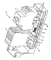
- the switchgear unit 2 comprises a contactor 4 designed as a standard unit as a switching unit for the function of the operational switching. Furthermore, a circuit breaker 6 is also provided as a standard unit for the function of the short-circuit protection.
- the contactor 4 and the power switch 6 are provided for the arrangement on an approximately L-shaped support 8.
- the carrier 8 is usually provided for snapping or pushing on a DIN rail in a cabinet.
- a printed circuit board 10 is integrated, which carries a plurality of electronic components 12 and contacting devices 14.
- a bus electronics is integrated, so that the switching device unit 2 can be connected to a bus system. This is, for example, a signal bus for the transmission of signals and / or a power bus for the power supply of the switching device unit 2.
- the function of the overload protection is realized separately from the circuit breaker 6.
- the function of the overload protection is realized by an electronic overload relay, which has a current transformer 16 in particular for each phase conductor of the power grid.
- some of the components 12 arranged on the printed circuit board 10 are associated with the electronic overload relay.
- the current transformer 16 is designed as a current measuring coil and serves to detect the magnetic field which is generated by the current-carrying phase conductor. From the signals of the current transformer 16, the respective current levels are determined by means of the components 12.
- the current transformers 16 extend into these free spaces.
- two current transformers 16 are shown, which extend into the recess 18 of the circuit breaker 6.
- the current transformer can be distributed over both recesses 18 and the gap 20 or be arranged exclusively in the intermediate space 20 or exclusively in the recess 18 of the contactor 4.
Landscapes
- Breakers (AREA)
- Patch Boards (AREA)
Applications Claiming Priority (3)
| Application Number | Priority Date | Filing Date | Title |
|---|---|---|---|
| DE10119458A DE10119458B4 (de) | 2001-04-20 | 2001-04-20 | Schaltgeräteeinheit für einen Verbraucher, insbesondere Motorstarter |
| DE10119458 | 2001-04-20 | ||
| PCT/DE2002/001282 WO2002086929A1 (de) | 2001-04-20 | 2002-04-08 | Schaltgeräteeinheit für einen verbraucher, insbesondere motorstarter |
Publications (2)
| Publication Number | Publication Date |
|---|---|
| EP1380042A1 EP1380042A1 (de) | 2004-01-14 |
| EP1380042B1 true EP1380042B1 (de) | 2006-06-21 |
Family
ID=7682136
Family Applications (1)
| Application Number | Title | Priority Date | Filing Date |
|---|---|---|---|
| EP02729856A Expired - Fee Related EP1380042B1 (de) | 2001-04-20 | 2002-04-08 | Schaltgeräteeinheit für einen verbraucher, insbesondere motorstarter |
Country Status (6)
| Country | Link |
|---|---|
| US (1) | US7012800B2 (ja) |
| EP (1) | EP1380042B1 (ja) |
| JP (1) | JP2004527993A (ja) |
| CN (1) | CN1258799C (ja) |
| DE (2) | DE10119458B4 (ja) |
| WO (1) | WO2002086929A1 (ja) |
Families Citing this family (20)
| Publication number | Priority date | Publication date | Assignee | Title |
|---|---|---|---|---|
| EP1564845A1 (de) * | 2004-02-16 | 2005-08-17 | Siemens Aktiengesellschaft | Installationsgerät und Installationsgerätegruppe mit Ansteuermodulen |
| EP1564848B1 (de) * | 2004-02-16 | 2013-10-16 | Siemens Aktiengesellschaft | Installationsgerät mit kodierbarer Steckschnittstelle und entsprechendes Zusatzmodul |
| DE102005016545B4 (de) * | 2005-04-08 | 2014-12-04 | Abb Ag | Modulrückwand für ein Schaltanlagenmodul, Schaltanlagenmodul und elektrische Schaltanlage |
| US7612972B2 (en) | 2005-09-30 | 2009-11-03 | Rockwell Automation Technologies, Inc. | Electrical contractor current sensing system and method |
| DE102006059384B4 (de) * | 2006-12-15 | 2013-02-21 | Siemens Aktiengesellschaft | Gerät mit einem Stromwandler zur Erfassung eines durch einen Stromleiter fließenden Stromes sowie Klemmen-/Stromwandler-Modul für ein derartiges Gerät |
| DE102007003329B3 (de) * | 2007-01-17 | 2008-04-10 | Siemens Ag | Kühlanordnung für in einem Gehäuse angeordnete elektrische Komponenten eines Sanftanlaufgerätes, und Sanftanlaufgerät |
| EP2015341B1 (de) * | 2007-07-10 | 2010-01-20 | Siemens Aktiengesellschaft | Gruppenabsicherungsmodul für eine Schaltgeräteanordnung sowie Schaltgeräteanordnung mit einem derartigen Gruppenabsicherungsmodul |
| JP5084779B2 (ja) * | 2008-11-27 | 2012-11-28 | 東京エレクトロン株式会社 | プラグインユニット |
| FR2943453B1 (fr) * | 2009-03-18 | 2011-06-24 | Schneider Toshiba Inverter | Ensemble de commande comportant un variateur de vitesse et un disjoncteur |
| US8456782B2 (en) | 2009-05-08 | 2013-06-04 | Rockwell Automation Technologies, Inc. | Cost effective design for a current transformer with an integrated magnetic actuator |
| EP2249368B1 (en) * | 2009-05-08 | 2018-06-13 | Rockwell Automation Technologies, Inc. | Circuit breaker system |
| US8681466B2 (en) | 2009-05-08 | 2014-03-25 | Rockwell Automation Technologies, Inc. | Magnetic core coupling in a current transformer with integrated magnetic actuator |
| KR101104103B1 (ko) * | 2011-11-08 | 2012-01-12 | 주식회사 비엠티 | 모듈형 안전부스바 |
| CN102683134A (zh) * | 2012-06-06 | 2012-09-19 | 伊发控股集团有限公司 | 控制与保护开关电器 |
| JP6522447B2 (ja) * | 2015-07-02 | 2019-05-29 | 株式会社日立ハイテクノロジーズ | 真空処理装置およびそれに用いる分電ユニット |
| FR3053829B1 (fr) * | 2016-07-08 | 2019-10-25 | Schneider Electric Industries Sas | Module d'interconnexion d'un disjoncteur et d'un contacteur pour un ensemble electrique comportant un capteur de tension |
| FR3053828B1 (fr) * | 2016-07-08 | 2019-10-25 | Schneider Electric Industries Sas | Module d'interconnexion d'un disjoncteur et d'un contacteur pour un ensemble electrique |
| DE102016118051A1 (de) | 2016-09-23 | 2018-03-29 | Eaton Electrical Ip Gmbh & Co. Kg | Motorstarter |
| DE102019116789A1 (de) * | 2019-06-21 | 2020-12-24 | Schneider Electric Industries Sas | Elektronisches Installationsgerät |
| US11515691B2 (en) * | 2020-09-30 | 2022-11-29 | Rockwell Automation Switzerland Gmbh | Modular low voltage power distribution module |
Family Cites Families (12)
| Publication number | Priority date | Publication date | Assignee | Title |
|---|---|---|---|---|
| FR2003575A1 (ja) | 1968-03-09 | 1969-11-07 | Stotz Kontakt Gmbh | |
| DE2904518C2 (de) * | 1979-02-07 | 1981-04-16 | Chemische Werke Hüls AG, 4370 Marl | Verfahren zur Herstellung von reinen α, ω-C↓6↓ bis C↓20↓-Alkenolen |
| US4258343A (en) * | 1979-02-12 | 1981-03-24 | Gould Inc. | Unitized combination starter |
| DE3817528A1 (de) | 1988-05-24 | 1989-12-07 | Licentia Gmbh | Motorstarter mit kurzschlussschutz |
| DE4335965A1 (de) * | 1993-10-21 | 1995-04-27 | Licentia Gmbh | Motorstarter mit integriertem Kurzschlußschutz |
| DE19521001A1 (de) * | 1995-06-08 | 1996-12-19 | Siemens Ag | Kommunikationsfähige Schaltgeräteeinheit |
| US5715129A (en) * | 1995-12-05 | 1998-02-03 | Eaton Corporation | Electronic overload relay having intrinsic power supply operable from power applied to contactor coil |
| FR2761538B1 (fr) * | 1997-04-01 | 1999-05-14 | Schneider Electric Sa | Ensemble de depart-moteur |
| DE19748429A1 (de) * | 1997-11-03 | 1999-05-06 | Siemens Ag | Kommunikationsfähige Schaltgeräteeinheit |
| DE19748531A1 (de) * | 1997-11-03 | 1999-05-06 | Siemens Ag | Aufbausystem für Verbraucherabzweige mit stehender Verdrahtung |
| FR2776861B1 (fr) * | 1998-03-27 | 2000-05-19 | Schneider Electric Sa | Ensemble de depart-moteur |
| DE10023966C1 (de) * | 2000-05-16 | 2001-11-08 | Siemens Ag | Verbraucherabzweig |
-
2001
- 2001-04-20 DE DE10119458A patent/DE10119458B4/de not_active Expired - Fee Related
-
2002
- 2002-04-08 US US10/475,342 patent/US7012800B2/en not_active Expired - Fee Related
- 2002-04-08 JP JP2002584351A patent/JP2004527993A/ja active Pending
- 2002-04-08 DE DE50207299T patent/DE50207299D1/de not_active Expired - Lifetime
- 2002-04-08 EP EP02729856A patent/EP1380042B1/de not_active Expired - Fee Related
- 2002-04-08 WO PCT/DE2002/001282 patent/WO2002086929A1/de active IP Right Grant
- 2002-04-08 CN CNB028085922A patent/CN1258799C/zh not_active Expired - Fee Related
Also Published As
| Publication number | Publication date |
|---|---|
| US20040246661A1 (en) | 2004-12-09 |
| DE10119458B4 (de) | 2004-08-19 |
| CN1528006A (zh) | 2004-09-08 |
| US7012800B2 (en) | 2006-03-14 |
| DE10119458A1 (de) | 2002-11-21 |
| WO2002086929A1 (de) | 2002-10-31 |
| EP1380042A1 (de) | 2004-01-14 |
| JP2004527993A (ja) | 2004-09-09 |
| DE50207299D1 (de) | 2006-08-03 |
| CN1258799C (zh) | 2006-06-07 |
Similar Documents
| Publication | Publication Date | Title |
|---|---|---|
| EP1380042B1 (de) | Schaltgeräteeinheit für einen verbraucher, insbesondere motorstarter | |
| EP2020014B1 (de) | Schalteinrichtung | |
| EP2619595B1 (de) | Messsystem zur überwachung mindestens einer phase eines systems | |
| EP0750382B1 (de) | Stromerfassungsgerät zur Anbringung an einem stromdurchflossenen Leiter | |
| DE19739780B4 (de) | Drehstrommotor | |
| EP1917672A1 (de) | Verbindungssystem mit einem elektromagnetischem schaltgerät, insbesondere schütz, und einem stecker | |
| EP3726560A1 (de) | Kompakt-schutzschaltgerät | |
| WO2001088939A1 (de) | Verbraucherabzweig | |
| EP0779640A2 (de) | Busfähiger Verstärkerbaustein für Antriebsanordnungen elektromagnetischer Schaltgeräte | |
| EP1203442A1 (de) | Kombination eines schützes mit einem sanftanlasser | |
| DE102008018256B4 (de) | Steuermodul mit Anschlusseinrichtungen zum Anschluss an Anschlussklemmen eines Verbraucherabzweiges sowie Verbraucherabzweig | |
| EP0889569B1 (de) | Installationsschaltereinheit | |
| EP1721375B1 (de) | Schutzgerät für einen verbraucherabzweig | |
| EP1570505B1 (de) | Niederspannungs-leistungsschalter | |
| EP0859395A2 (de) | Niederspannungs-Leistungsschalter mit Wahlweise einbaubarem Messwandler | |
| DE60007557T2 (de) | Fehlerstromschutzschalter | |
| DE19706961C2 (de) | Zusatzeinrichtung zur Meldung des Schaltzustandes oder einer Auslösung eines Niederspannungsschaltgerätes | |
| DE102007019021A1 (de) | Leistungsschütz, insbesondere Vakuumschütz | |
| DE102020200993A1 (de) | Fernantrieb, Anordnung mit einem Fernantrieb sowie Verfahren | |
| AT406431B (de) | Einrichtung zur analyse von in einer elektrischen anlage auftretenden erdfehlerströmen und von dieser angesteuertes schaltgerät | |
| EP4274041A1 (de) | Modulares isolierstoffgehäuse und mehrpoliges modulares reiheneinbaugerät | |
| EP4213175A1 (de) | Niederspannungs-schutzschaltgerät mit einer leiterplatte und einem spannungsabgriff und montageverfahren | |
| WO1999054980A1 (de) | Entstörmodul | |
| DE19546268A1 (de) | Busfähiger Verstärkerbaustein für Antriebsanordnungen elektromagnetischer Schaltgeräte | |
| EP4080539A1 (de) | Schutzschalter mit überlastschutz |
Legal Events
| Date | Code | Title | Description |
|---|---|---|---|
| PUAI | Public reference made under article 153(3) epc to a published international application that has entered the european phase |
Free format text: ORIGINAL CODE: 0009012 |
|
| 17P | Request for examination filed |
Effective date: 20030905 |
|
| AK | Designated contracting states |
Kind code of ref document: A1 Designated state(s): AT BE CH CY DE DK ES FI FR GB GR IE IT LI LU MC NL PT SE TR |
|
| 17Q | First examination report despatched |
Effective date: 20040712 |
|
| GRAP | Despatch of communication of intention to grant a patent |
Free format text: ORIGINAL CODE: EPIDOSNIGR1 |
|
| GRAS | Grant fee paid |
Free format text: ORIGINAL CODE: EPIDOSNIGR3 |
|
| GRAA | (expected) grant |
Free format text: ORIGINAL CODE: 0009210 |
|
| AK | Designated contracting states |
Kind code of ref document: B1 Designated state(s): DE FR IT |
|
| PG25 | Lapsed in a contracting state [announced via postgrant information from national office to epo] |
Ref country code: IT Free format text: LAPSE BECAUSE OF FAILURE TO SUBMIT A TRANSLATION OF THE DESCRIPTION OR TO PAY THE FEE WITHIN THE PRESCRIBED TIME-LIMIT;WARNING: LAPSES OF ITALIAN PATENTS WITH EFFECTIVE DATE BEFORE 2007 MAY HAVE OCCURRED AT ANY TIME BEFORE 2007. THE CORRECT EFFECTIVE DATE MAY BE DIFFERENT FROM THE ONE RECORDED. Effective date: 20060621 |
|
| REF | Corresponds to: |
Ref document number: 50207299 Country of ref document: DE Date of ref document: 20060803 Kind code of ref document: P |
|
| ET | Fr: translation filed | ||
| PLBE | No opposition filed within time limit |
Free format text: ORIGINAL CODE: 0009261 |
|
| STAA | Information on the status of an ep patent application or granted ep patent |
Free format text: STATUS: NO OPPOSITION FILED WITHIN TIME LIMIT |
|
| 26N | No opposition filed |
Effective date: 20070322 |
|
| REG | Reference to a national code |
Ref country code: FR Ref legal event code: PLFP Year of fee payment: 15 |
|
| REG | Reference to a national code |
Ref country code: FR Ref legal event code: PLFP Year of fee payment: 16 |
|
| PGFP | Annual fee paid to national office [announced via postgrant information from national office to epo] |
Ref country code: DE Payment date: 20170619 Year of fee payment: 16 Ref country code: FR Payment date: 20170425 Year of fee payment: 16 |
|
| PGFP | Annual fee paid to national office [announced via postgrant information from national office to epo] |
Ref country code: IT Payment date: 20170426 Year of fee payment: 16 |
|
| REG | Reference to a national code |
Ref country code: DE Ref legal event code: R119 Ref document number: 50207299 Country of ref document: DE |
|
| PG25 | Lapsed in a contracting state [announced via postgrant information from national office to epo] |
Ref country code: DE Free format text: LAPSE BECAUSE OF NON-PAYMENT OF DUE FEES Effective date: 20181101 |
|
| PG25 | Lapsed in a contracting state [announced via postgrant information from national office to epo] |
Ref country code: FR Free format text: LAPSE BECAUSE OF NON-PAYMENT OF DUE FEES Effective date: 20180430 Ref country code: IT Free format text: LAPSE BECAUSE OF NON-PAYMENT OF DUE FEES Effective date: 20180408 |