EP1380042B1 - Switchgear unit for a consumer, especially a motor starter - Google Patents
Switchgear unit for a consumer, especially a motor starter Download PDFInfo
- Publication number
- EP1380042B1 EP1380042B1 EP02729856A EP02729856A EP1380042B1 EP 1380042 B1 EP1380042 B1 EP 1380042B1 EP 02729856 A EP02729856 A EP 02729856A EP 02729856 A EP02729856 A EP 02729856A EP 1380042 B1 EP1380042 B1 EP 1380042B1
- Authority
- EP
- European Patent Office
- Prior art keywords
- unit
- circuit breaker
- switchgear unit
- overload relay
- protection
- Prior art date
- Legal status (The legal status is an assumption and is not a legal conclusion. Google has not performed a legal analysis and makes no representation as to the accuracy of the status listed.)
- Expired - Fee Related
Links
Images
Classifications
-
- H—ELECTRICITY
- H01—ELECTRIC ELEMENTS
- H01H—ELECTRIC SWITCHES; RELAYS; SELECTORS; EMERGENCY PROTECTIVE DEVICES
- H01H89/00—Combinations of two or more different basic types of electric switches, relays, selectors and emergency protective devices, not covered by any single one of the other main groups of this subclass
- H01H89/06—Combination of a manual reset circuit with a contactor, i.e. the same circuit controlled by both a protective and a remote control device
-
- H—ELECTRICITY
- H01—ELECTRIC ELEMENTS
- H01H—ELECTRIC SWITCHES; RELAYS; SELECTORS; EMERGENCY PROTECTIVE DEVICES
- H01H2300/00—Orthogonal indexing scheme relating to electric switches, relays, selectors or emergency protective devices covered by H01H
- H01H2300/03—Application domotique, e.g. for house automation, bus connected switches, sensors, loads or intelligent wiring
-
- H—ELECTRICITY
- H01—ELECTRIC ELEMENTS
- H01H—ELECTRIC SWITCHES; RELAYS; SELECTORS; EMERGENCY PROTECTIVE DEVICES
- H01H71/00—Details of the protective switches or relays covered by groups H01H73/00 - H01H83/00
- H01H71/10—Operating or release mechanisms
- H01H71/12—Automatic release mechanisms with or without manual release
- H01H71/123—Automatic release mechanisms with or without manual release using a solid-state trip unit
-
- Y—GENERAL TAGGING OF NEW TECHNOLOGICAL DEVELOPMENTS; GENERAL TAGGING OF CROSS-SECTIONAL TECHNOLOGIES SPANNING OVER SEVERAL SECTIONS OF THE IPC; TECHNICAL SUBJECTS COVERED BY FORMER USPC CROSS-REFERENCE ART COLLECTIONS [XRACs] AND DIGESTS
- Y02—TECHNOLOGIES OR APPLICATIONS FOR MITIGATION OR ADAPTATION AGAINST CLIMATE CHANGE
- Y02B—CLIMATE CHANGE MITIGATION TECHNOLOGIES RELATED TO BUILDINGS, e.g. HOUSING, HOUSE APPLIANCES OR RELATED END-USER APPLICATIONS
- Y02B90/00—Enabling technologies or technologies with a potential or indirect contribution to GHG emissions mitigation
- Y02B90/20—Smart grids as enabling technology in buildings sector
-
- Y—GENERAL TAGGING OF NEW TECHNOLOGICAL DEVELOPMENTS; GENERAL TAGGING OF CROSS-SECTIONAL TECHNOLOGIES SPANNING OVER SEVERAL SECTIONS OF THE IPC; TECHNICAL SUBJECTS COVERED BY FORMER USPC CROSS-REFERENCE ART COLLECTIONS [XRACs] AND DIGESTS
- Y04—INFORMATION OR COMMUNICATION TECHNOLOGIES HAVING AN IMPACT ON OTHER TECHNOLOGY AREAS
- Y04S—SYSTEMS INTEGRATING TECHNOLOGIES RELATED TO POWER NETWORK OPERATION, COMMUNICATION OR INFORMATION TECHNOLOGIES FOR IMPROVING THE ELECTRICAL POWER GENERATION, TRANSMISSION, DISTRIBUTION, MANAGEMENT OR USAGE, i.e. SMART GRIDS
- Y04S20/00—Management or operation of end-user stationary applications or the last stages of power distribution; Controlling, monitoring or operating thereof
- Y04S20/14—Protecting elements, switches, relays or circuit breakers
Definitions
- the invention relates to a switching device unit for a consumer, in particular a motor starter, with a switching unit for a proper operation of the consumer and with the functions short-circuit protection and overload protection.
- the switchgear unit is generally referred to as a load feeder and usually arranged in a cabinet on a standard DIN rail next to other load branches.
- the arranged in a cabinet load feeders are put together in a modular design to meet the respective requirements can.
- load feeders are provided in particular in industrial plant technology for controlling and switching high currents and voltages.
- a three-phase motor is driven with the switching device unit.
- the switchgear unit is referred to in this case as a motor starter.
- the switching device unit of a motor starter usually has three functions to protect the motor.
- the first function relates to the proper operation of the engine and is by its own standard unit, usually a so-called contactor, realized.
- the contactor is designed for the repeated operational switching on and off of high currents.
- the functions short-circuit protection and overload protection are integrated in a standard unit called a circuit breaker in a switchgear unit.
- the circuit breaker disconnects the load from the mains in the event of a short circuit and also when too high a current occurs.
- the two standard units are on one common carrier arranged side by side and form the switching device unit.
- a motor starter with integrated short-circuit protection can be seen, in which one behind the other a circuit breaker, an electronic trip unit and a contactor are arranged.
- the electronic trip unit is integrated together with the circuit breaker in a common housing.
- the trip unit includes a trigger, which ensures thermal overload protection of the motor.
- a contactor is provided with a short-circuit release provided as an attachment and with a mounting piece which contains a thermal overcurrent release.
- a switching device unit which includes a contactor and a circuit breaker each as separate units. These units are arranged on an intermediate carrier, in which a printed circuit board is integrated with an electronics. About this electronics, it is possible to control the scarf unit via a bus system.
- two bus systems are provided, namely a data bus for signal exchange and an energy bus for power supply.
- an electronic circuit is alternatively proposed, however, which is less suitable or very complicated and expensive compared to the electromechanically designed units contactor and circuit breaker for the switching of very high currents.
- the object of the invention is to provide a simple as possible and inexpensive switchgear unit.
- a switchgear unit in particular for a motor starter, with the radio tion-appropriate switching, short-circuit protection and overload protection provided that each of these functions is implemented in a separate functional unit.
- Operational switching is provided by a switching unit, in particular a contactor, the short-circuit protection function of a circuit breaker and the overload protection function of an overload protection formed separately from the circuit breaker to ensure safe, the circuit breaker must be designed specifically for the switching current provided in each case.
- Switching current is understood to mean that current for which the switchgear unit is designed. This means that, for example, for the switching current range between 0 and 25 A, about twenty differently designed different circuit breakers are required. This leads to a considerable cost and requires great care in the selection of the appropriate circuit breaker.
- the function overload protection no longer needs to be integrated in the circuit breaker and this can be designed primarily for the short-circuit protection function.
- the circuit breaker is thereby significantly simpler in construction and thus cheaper and can also be used over a wide current range.
- the function of the overload protection implemented in the overload relay is also comparatively simple due to the decoupling of the short-circuit protection.
- the overload relay is designed as an electronic overload relay, which in particular has a current transformer.
- This current transformer is arranged in the manner of a current measuring coil around a conductor to be monitored and detects the magnetic field generated by the current-carrying conductor.
- An evaluation electronics connected to the current transformer determines the current flowing through the conductor. Due to this principle, the electronic overload relay can be used for a very wide current range. The determination of the current level at which the overload relay is to be triggered is made via the electronics and can be set almost as desired.
- the Switching unit and the circuit breaker are preferably designed as standard components, which are arranged to form a free space on a support. At least one component of the overload relay extends into this free space.
- Such standard units usually have on their underside for attachment to a DIN rail on a recess which forms a space in which the component preferably engages.
- a gap is usually arranged between the contactor and the circuit breaker, which also advantageously serves as a free space for the arrangement of a component of the overload relay.
- the current transformer extends into the free space, since this takes up the largest space due to the design as a coil.
- a separate current transformer is provided for each phase of the power grid. These are thus arranged, for example, distributed in the two recesses or in the intermediate space.
- the component extending into the clearances is disposed on the support on which the contactor and the circuit breaker are also mounted.
- the components of the overload relay are arranged on a printed circuit board held by the carrier.
- the circuit board simultaneously carries a bus electronics, so the switchgear unit is designed for connection to a bus system.
- the switchgear unit is designed for connection to a bus system.
- space requirements are minimized and kept low production costs in a particularly efficient manner.
- the circuit board used in modern switchgear units today usually for the bus electronics only needs to be extended by a few electronic functionalities. Due to the high level of automation in printed circuit board production, this requires only a small additional effort. This is offset by significant savings, since on the one hand the circuit breaker without the function overload protection can be simplified and can be used by default for a wide current range.
- the integration of the electronic overload relay on the printed circuit board with the electrical transformers extending into the free spaces achieves a very small construction volume, which additionally keeps the costs for installing the switchgear unit low.
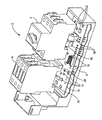
- the switchgear unit 2 comprises a contactor 4 designed as a standard unit as a switching unit for the function of the operational switching. Furthermore, a circuit breaker 6 is also provided as a standard unit for the function of the short-circuit protection.
- the contactor 4 and the power switch 6 are provided for the arrangement on an approximately L-shaped support 8.
- the carrier 8 is usually provided for snapping or pushing on a DIN rail in a cabinet.
- a printed circuit board 10 is integrated, which carries a plurality of electronic components 12 and contacting devices 14.
- a bus electronics is integrated, so that the switching device unit 2 can be connected to a bus system. This is, for example, a signal bus for the transmission of signals and / or a power bus for the power supply of the switching device unit 2.
- the function of the overload protection is realized separately from the circuit breaker 6.
- the function of the overload protection is realized by an electronic overload relay, which has a current transformer 16 in particular for each phase conductor of the power grid.
- some of the components 12 arranged on the printed circuit board 10 are associated with the electronic overload relay.
- the current transformer 16 is designed as a current measuring coil and serves to detect the magnetic field which is generated by the current-carrying phase conductor. From the signals of the current transformer 16, the respective current levels are determined by means of the components 12.
- the current transformers 16 extend into these free spaces.
- two current transformers 16 are shown, which extend into the recess 18 of the circuit breaker 6.
- the current transformer can be distributed over both recesses 18 and the gap 20 or be arranged exclusively in the intermediate space 20 or exclusively in the recess 18 of the contactor 4.
Abstract
Description
Die Erfindung betrifft eine Schaltgeräteeinheit für einen Verbraucher, insbesondere einen Motorstarter, mit einer Schalteinheit für ein betriebsgemäßes Schalten des Verbrauchers und mit den Funktionen Kurzschlussschutz und Überlastschutz.The invention relates to a switching device unit for a consumer, in particular a motor starter, with a switching unit for a proper operation of the consumer and with the functions short-circuit protection and overload protection.
Die Schaltgeräteeinheit wird allgemein auch als Verbraucherabzweig bezeichnet und üblicherweise in einem Schaltschrank auf einer genormten Hutschiene neben weiteren Verbraucherabzweigen angeordnet. Die in einem Schaltschrank angeordneten Verbraucherabzweige sind in einer modularen Bauweise zusammengestellt, um den jeweiligen Anforderungen entsprechen zu können. Derartige Verbraucherabzweige sind insbesondere in der industriellen Anlagentechnik zum Steuern und Schalten von hohen Strömen und Spannungen vorgesehen. Insbesondere wird mit der Schaltgeräteeinheit ein Drehstrommotor angesteuert. Die Schaltgeräteeinheit wird in diesem Fall auch als Motorstarter bezeichnet.The switchgear unit is generally referred to as a load feeder and usually arranged in a cabinet on a standard DIN rail next to other load branches. The arranged in a cabinet load feeders are put together in a modular design to meet the respective requirements can. Such load feeders are provided in particular in industrial plant technology for controlling and switching high currents and voltages. In particular, a three-phase motor is driven with the switching device unit. The switchgear unit is referred to in this case as a motor starter.
Die Schaltgeräteeinheit eines Motorstarters weist zum Schutz des Motors in der Regel drei Funktionen auf. Die erste Funktion betrifft das betriebsgemäße Schalten des Motors und ist durch eine eigene Standardbaueinheit, üblicherweise ein sogenanntes Schütz, verwirklicht. Das Schütz ist für das wiederholte betriebsgemäße Ein- und Ausschalten von hohen Strömen ausgebildet. Weiterhin sind in einer Schaltgeräteeinheit die Funktionen Kurzschlussschutz und Überlastschutz in einer als Leistungsschalter bezeichneten Standardbaueinheit integriert. Der Leistungsschalter trennt den Verbraucher vom Netz bei Auftreten eines Kurzschlusses und auch bei Auftreten eines zu hohen Stroms. Die beiden Standardbaueinheiten sind auf einem gemeinsamen Träger nebeneinander angeordnet und bilden die Schaltgeräteeinheit.The switching device unit of a motor starter usually has three functions to protect the motor. The first function relates to the proper operation of the engine and is by its own standard unit, usually a so-called contactor, realized. The contactor is designed for the repeated operational switching on and off of high currents. Furthermore, the functions short-circuit protection and overload protection are integrated in a standard unit called a circuit breaker in a switchgear unit. The circuit breaker disconnects the load from the mains in the event of a short circuit and also when too high a current occurs. The two standard units are on one common carrier arranged side by side and form the switching device unit.
Aus der DE 43 35 965 ist ein Motorstarter mit integriertem Kurzschlussschutz zu entnehmen, bei dem hintereinander ein Leistungsschalter, eine elektronische Auslöseeinheit sowie ein Schütz angeordnet sind. Die elektronische Auslöseeinheit ist zusammen mit dem Leistungsschalter in einem gemeinsamen Gehäuse integriert. Die Auslöseeinheit umfasst hierbei einen Auslöser, der den thermischen Überlastschutz des Motors gewährleistet.From DE 43 35 965 a motor starter with integrated short-circuit protection can be seen, in which one behind the other a circuit breaker, an electronic trip unit and a contactor are arranged. The electronic trip unit is integrated together with the circuit breaker in a common housing. The trip unit includes a trigger, which ensures thermal overload protection of the motor.
Aus der FR 2 003 575 ist ein Schütz mit einem als Anbauteil vorgesehenen Kurzschlussauslöser und mit einem Anbaustück versehen, das einen thermischen Überstromauslöser enthält.From FR 2 003 575 a contactor is provided with a short-circuit release provided as an attachment and with a mounting piece which contains a thermal overcurrent release.
Aus der WO 99/23737 ist eine Schaltgeräteeinheit bekannt, die einen Schütz und einen Leistungsschalter jeweils als separate Baueinheiten beinhaltet. Diese Baueinheiten sind auf einem Zwischenträger angeordnet, in dem eine Leiterplatte mit einer Elektronik integriert ist. Über diese Elektronik besteht die Mögiichkeit, die Schal-tgeräteeinheit über ein Bussystem anzusteuern. Hierbei sind insbesondere zwei Bussysteme vorgesehen, nämlich ein Datenbus zum Signalaustausch und ein Energiebus zur Energieversorgung. Anstelle der standardgemäßen Baueinheiten Schütz und Leistungsschalter wird alternativ eine elektronische Schaltung vorgeschlagen, die jedoch im Vergleich zu den elektromechanisch ausgebildeten Baueinheiten Schütz und Leistungsschalter für das Schalten von sehr hohen Strömen weniger geeignet oder sehr aufwendig und teuer ist.From WO 99/23737 a switching device unit is known which includes a contactor and a circuit breaker each as separate units. These units are arranged on an intermediate carrier, in which a printed circuit board is integrated with an electronics. About this electronics, it is possible to control the scarf unit via a bus system. In particular, two bus systems are provided, namely a data bus for signal exchange and an energy bus for power supply. Instead of the standard units contactor and circuit breaker, an electronic circuit is alternatively proposed, however, which is less suitable or very complicated and expensive compared to the electromechanically designed units contactor and circuit breaker for the switching of very high currents.
Aufgabe der Erfindung ist es, eine möglichst einfach aufgebaute und kostengünstige Schaltgeräteeinheit anzugeben.The object of the invention is to provide a simple as possible and inexpensive switchgear unit.
Die Aufgabe wird gemäß der Erfindung gelöst durch die Merkmale des Patentanspruchs 1. Danach ist für eine Schaltgeräteeinheit, insbesondere für einen Motorstarter, mit den Funk tionen betriebsgemäßes Schalten, Kurzschlussschutz und Überlastschutz vorgesehen, dass jede dieser Funktionen in einer separaten Funktionseinheit verwirklicht ist. Das betriebsgemäße Schalten wird dabei von einer Schalteinheit, insbesondere Schütz, die Funktion Kurzschlussschutz von einem Leistungsschalter und die Funktion Überlastschutz von einem getrennt vom Leistungsschalter ausgebildeten Überlastschutz sicher zu gewährleisten, muss der Leistungsschalter spezifisch für den jeweils vorgesehenen Schaltstrom ausgelegt werden. Unter Schaltstrom wird hierbei derjenige Strom verstanden, für den die Schaltgeräteeinheit ausgelegt ist. Dies bedeutet, dass beispielsweise für den Schaltstrombereich zwischen 0 und 25 A etwa zwanzig unterschiedlich ausgelegte verschiedene Leistungsschalter erforderlich sind. Dies führt zu einem erheblichen Kostenaufwand und bedarf einer hohen Sorgfalt bei der Auswahl des geeigneten Leistungsschalters.The object is achieved according to the invention by the features of claim 1. Thereafter, for a switchgear unit, in particular for a motor starter, with the radio tion-appropriate switching, short-circuit protection and overload protection provided that each of these functions is implemented in a separate functional unit. Operational switching is provided by a switching unit, in particular a contactor, the short-circuit protection function of a circuit breaker and the overload protection function of an overload protection formed separately from the circuit breaker to ensure safe, the circuit breaker must be designed specifically for the switching current provided in each case. Switching current is understood to mean that current for which the switchgear unit is designed. This means that, for example, for the switching current range between 0 and 25 A, about twenty differently designed different circuit breakers are required. This leads to a considerable cost and requires great care in the selection of the appropriate circuit breaker.
Erfindungsgemäß ist aufgrund der Trennung der Funktion Kurzschlussschutz und Überlastschutz eine deutliche Vereinfachung erreicht. Insbesondere braucht die Funktion Überlastschutz nicht mehr im Leistungsschalter integriert zu werden und dieser kann in erster Linie für die Funktion Kurzschlussschutz ausgelegt sein. Der Leistungsschalter wird dadurch deutlich einfacher im Aufbau und damit kostengünstiger und kann zudem über einen weiten Strombereich eingesetzt werden. Auch die im Überlastrelais verwirklichte Funktion des Überlastschutzes ist aufgrund deren Entkopplung vom Kurzschlussschutz vergleichsweise einfach auszulegen.According to the invention, a significant simplification is achieved due to the separation of the function short-circuit protection and overload protection. In particular, the function overload protection no longer needs to be integrated in the circuit breaker and this can be designed primarily for the short-circuit protection function. The circuit breaker is thereby significantly simpler in construction and thus cheaper and can also be used over a wide current range. The function of the overload protection implemented in the overload relay is also comparatively simple due to the decoupling of the short-circuit protection.
Bevorzugt ist das Überlastrelais als elektronisches Überlastrelais ausgebildet, welches insbesondere einen Stromwandler aufweist. Dieser Stromwandler ist nach Art einer Strommessspule um einen zu überwachenden Leiter angeordnet und erfasst das vom stromdurchflossenen Leiter erzeugte magnetische Feld. Eine an den Stromwandler angeschlossene Auswerteelektronik ermittelt hieraus den durch den Leiter fließenden Strom. Aufgrund dieses Prinzips ist das elektronische Überlastrelais für einen sehr weiten Strombereich einsetzbar. Die Bestimmung, ab welcher Stromhöhe das Überlastrelais auslösen soll, erfolgt über die Elektronik und kann nahezu beliebig eingestellt werden.Preferably, the overload relay is designed as an electronic overload relay, which in particular has a current transformer. This current transformer is arranged in the manner of a current measuring coil around a conductor to be monitored and detects the magnetic field generated by the current-carrying conductor. An evaluation electronics connected to the current transformer determines the current flowing through the conductor. Due to this principle, the electronic overload relay can be used for a very wide current range. The determination of the current level at which the overload relay is to be triggered is made via the electronics and can be set almost as desired.
Um einen möglichst kostengünstigen und möglichst kompakten Aufbau der Schaltgeräteeinheit zu ermöglichen, sind die Schalteinheit und der Leistungsschalter vorzugsweise als Standardbauteile ausgelegt, die unter Ausbildung eines Freiraums auf einem Träger angeordnet sind. In diesen Freiraum reicht zumindest ein Bauteil des Überlastrelais hinein. Durch diese Maßnahme lässt sich der erforderliche Bauraum für die Schaltgeräteeinheit gering halten, was zu einem geringen Platzbedarf im Schaltschrank und zu geringen Installationskosten führt.In order to enable the most cost-effective and compact as possible construction of the switching device unit, are the Switching unit and the circuit breaker are preferably designed as standard components, which are arranged to form a free space on a support. At least one component of the overload relay extends into this free space. By this measure, the required space for the switchgear unit can be kept low, resulting in a small footprint in the cabinet and low installation costs.
Für die kostengünstige Ausgestaltung ist die Verwendung von Standardbaueinheiten für die Schalteinheit (Schütz) und den Leistungsschalter von besonderem Vorteil. Derartige Standardbaueinheiten weisen üblicherweise an ihrer Unterseite für die Befestigung auf einer Hutschiene eine Aussparung auf, die einen Freiraum bildet, in den das Bauteil vorzugsweise eingreift. Zudem ist zwischen dem Schütz und dem Leistungsschalter üblicherweise ein Zwischenraum angeordnet, der ebenfalls vorteilhafterweise als Freiraum für die Anordnung eines Bauteils des Überlastrelais dient.For the cost-effective design of the use of standard units for the switching unit (contactor) and the circuit breaker is particularly advantageous. Such standard units usually have on their underside for attachment to a DIN rail on a recess which forms a space in which the component preferably engages. In addition, a gap is usually arranged between the contactor and the circuit breaker, which also advantageously serves as a free space for the arrangement of a component of the overload relay.
Zweckdienlicherweise reicht dabei insbesondere der Stromwandler in den Freiraum hinein, da dieser aufgrund der Ausbildung als Spule den größten Bauraum in Anspruch nimmt. Im Überlastrelais ist für jede Phase des Stromnetzes ein eigener Stromwandler vorgesehen. Diese werden also beispielsweise verteilt in den beiden Aussparungen oder im Zwischenraum angeordnet.Conveniently, in particular, the current transformer extends into the free space, since this takes up the largest space due to the design as a coil. In the overload relay, a separate current transformer is provided for each phase of the power grid. These are thus arranged, for example, distributed in the two recesses or in the intermediate space.
Zweckdienlicherweise ist für eine kompakte Anordnung das Bauteil, das in die Freiräume hineinreicht, auf dem Träger angeordnet, auf dem auch das Schütz und der Leistungsschalter befestigt sind.Conveniently, for a compact arrangement, the component extending into the clearances is disposed on the support on which the contactor and the circuit breaker are also mounted.
In einer besonders zweckdienlichen Ausgestaltung ist vorgesehen, dass die Bauteile des Überlastrelais auf einer vom Träger gehaltenen Leiterplatte angeordnet sind. Vorzugsweise trägt die Leiterplatte gleichzeitig eine Buselektronik, so dass die Schaltgeräteeinheit zum Anschluss an ein Bussystem ausgebildet ist. Mit der Integration des elektronischen Überlastrelais auf der Leiterplatte werden in besonders effizienter Weise der Platzbedarf minimiert und die Herstellungskosten gering gehalten. Denn die bei modernen Schaltgeräteeinheiten heute bereits üblicherweise für die Buselektronik verwendete Leiterplatte braucht lediglich um einige wenige elektronische Funktionalitäten erweitert werden. Aufgrund des hohen Automatisierungsgrads in der Leiterplattenherstellung erfordert dies einen nur geringen zusätzlichen Aufwand. Dem stehen erhebliche Einsparungen gegenüber, da einerseits der Leistungsschalter ohne die Funktion Überlastschutz vereinfacht ausgebildet sein und standardmäßig für einen weiten Strombereich herangezogen werden kann. Gleichzeitig wird andererseits durch die Integration des elektronischen Überlastrelais auf der Leiterplatte mit den in die Freiräume hineinreichenden Stromwandlern ein sehr geringes Bauvolumen erreicht, das zusätzlich die Kosten für die Installation der Schaltgeräteeinheit niedrig hält.In a particularly expedient embodiment, it is provided that the components of the overload relay are arranged on a printed circuit board held by the carrier. Preferably, the circuit board simultaneously carries a bus electronics, so the switchgear unit is designed for connection to a bus system. With the integration of the electronic overload relay on the circuit board space requirements are minimized and kept low production costs in a particularly efficient manner. Because the circuit board used in modern switchgear units today usually for the bus electronics only needs to be extended by a few electronic functionalities. Due to the high level of automation in printed circuit board production, this requires only a small additional effort. This is offset by significant savings, since on the one hand the circuit breaker without the function overload protection can be simplified and can be used by default for a wide current range. At the same time, on the other hand, the integration of the electronic overload relay on the printed circuit board with the electrical transformers extending into the free spaces achieves a very small construction volume, which additionally keeps the costs for installing the switchgear unit low.
Ein Ausführungsbeispiel der Erfindung wird im Folgenden anhand der einzigen Figur der Zeichnung näher erläutert. Diese zeigt in einer stark vereinfachten schematischen und perspektivischen Darstellung eine Schaltgeräteeinheit.An embodiment of the invention will be explained in more detail below with reference to the single figure of the drawing. This shows a simplified schematic and perspective view of a switching device unit.
Die Schaltgeräteeinheit 2 umfasst ein als Standardbaueinheit ausgebildetes Schütz 4 als Schalteinheit für die Funktion des betriebsgemäßen Schaltens. Weiterhin ist ebenfalls als Standardbaueinheit für die Funktion des Kurzschlussschutzes ein Leistungsschalter 6 vorgesehen. Das Schütz 4 und der Leistungschalter 6 sind für die Anordnung auf einem in etwa L-förmig ausgebildeten Träger 8 vorgesehen. Der Träger 8 ist üblicherweise zum Aufschnappen oder Aufschieben auf einer Hutschiene in einem Schaltschrank vorgesehen.The switchgear unit 2 comprises a contactor 4 designed as a standard unit as a switching unit for the function of the operational switching. Furthermore, a circuit breaker 6 is also provided as a standard unit for the function of the short-circuit protection. The contactor 4 and the power switch 6 are provided for the arrangement on an approximately L-shaped support 8. The carrier 8 is usually provided for snapping or pushing on a DIN rail in a cabinet.
Im Boden des Trägers 8 ist eine Leiterplatte 10 integriert, die eine Mehrzahl von elektronischen Bauelementen 12 sowie Kontaktierungseinrichtungen 14 trägt. Auf der Leiterplatte 10 ist insbesondere eine Buselektronik integriert, so dass die Schaltgeräteeinheit 2 an einem Bussystem angeschlossen werden kann. Dies ist beispielsweise ein Signalbus zur Übermittlung von Signalen und/oder ein Energiebus zur Energieversorgung der Schaltgeräteeinheit 2.In the bottom of the carrier 8, a
Erfindungsgemäß ist nunmehr vorgesehen, dass die Funktion des Überlastschutzes getrennt vom Leistungsschalter 6 verwirklicht ist. Hierzu ist die Funktion des Überlastschutzes durch ein elektronisches Überlastrelais verwirklicht, das insbesondere für jeden Phasenleiter des Stromnetzes einen Stromwandler 16 aufweist. Zum elektronischen Überlastrelais zugehörig sind darüber hinaus einige der auf der Leiterplatte 10 angeordneten Bauelemente 12. Der Stromwandler 16 ist als Strommessspule ausgebildet und dient zur Erfassung des Magnetfeldes, das vom stromdurchflossenen Phasenleiter erzeugt wird. Aus den Signalen der Stromwandler 16 werden mittels der Bauelemente 12 die jeweiligen Stromhöhen ermittelt.According to the invention it is now provided that the function of the overload protection is realized separately from the circuit breaker 6. For this purpose, the function of the overload protection is realized by an electronic overload relay, which has a
Aufgrund der Verwendung von Standardbaueinheiten für das Schütz 4 und den Leistungsschalter 6 haben diese an ihrer Unterseite jeweils eine Aussparung 18 für eine Anordnung auf einer Hutschiene. Bei der Anordnung des Schützes 4 und des Leistungsschalters 6 auf dem Träger 8 ist konstruktionsbedingt zwischen diesen Baueinheiten ein Zwischenraum 20 ausgebildet. Die Aussparungen 18 sowie der Zwischenraum 20 bilden konstruktionsbedingte Freiräume.Due to the use of standard units for the contactor 4 and the circuit breaker 6, these each have on their underside a
Um diese vorhandenen Freiräume sinnvoll auszunutzen, reichen die Stromwandler 16 in diese Freiräume hinein. Im Ausführungsbeispiel sind zwei Stromwandler 16 dargestellt, die in die Aussparung 18 des Leistungsschalters 6 hineinreichen. Alternativ hierzu können die Stromwandler auch über beide Aussparungen 18 und den Zwischenraum 20 verteilt angeordnet sein oder ausschließlich im Zwischenraum 20 oder ausschließlich in der Aussparung 18 des Schützes 4 angeordnet sein.To make good use of these existing open spaces, the
Aufgrund der Ausnutzung der konstruktionsbedingt bestehenden Freiräume ist der Platzbedarf für die Schaltgeräteeinheit 2 insgesamt sehr gering gehalten. Dadurch wird ein kompaktes Bauvolumen erreicht und der Platzbedarf im Schaltschrank und damit die Installationskosten sind gering gehalten. Zudem ist eine Vereinfachung des Leistungsschalters durch die Integration der Funktion des Überlastschutzes in einer vom Leistungsschalter 6 getrennten Einheit, dem elektronischen Überlastrelais, ermöglicht.Due to the utilization of the design-related existing spaces of the space required for the switching device unit 2 is kept very low overall. As a result, a compact volume is achieved and the space required in the cabinet and thus the installation costs are kept low. In addition, a simplification of the circuit breaker by the integration of the function of the overload protection in a separate from the circuit breaker 6 unit, the electronic overload relay is possible.
Claims (6)
- Switchgear unit (2) for a load, in particular a motor starter, having a switching unit (4) for switching the load during operation, and having the functions of short-circuit protection and overload protection, the function of short-circuit protection being integrated in a circuit breaker (6), and the function of overload protection being integrated in a separate functional unit in an electronic overload relay (12, 16) which is separate from the circuit breaker (6), and the switching unit (4) and the circuit breaker (6) being in the form of standard components, each having a free space underneath, which is provided for mounting them on a top-hat rail, and at least one component (16) of the electronic overload relay (12, 16) extending into the free space.
- Switchgear unit (2) according to Claim 1, characterized in that the circuit breaker (6) and the switching unit (4) are arranged next to one another so as to form an interspace (20) into which the component (16) or a further component (16) extends.
- Switchgear unit (2) according to either of Claims 1 and 2, characterized in that the overload relay (12, 16) has a current transformer (16) which extends into the free space (18, 20).
- Switchgear unit (2) according to one of Claims 1 to 3, characterized in that the component (16) of the overload relay (12, 16) is arranged on the carrier (8).
- Switchgear unit (2) according to one of Claims 1 to 4, characterized in that the components (12, 16) of the overload relay are arranged on a printed circuit board (10) on the carrier (8).
- Switchgear unit (2) according to Claim 5, characterized in that the printed circuit board (10) is fitted with an electronic bus system (12).
Applications Claiming Priority (3)
| Application Number | Priority Date | Filing Date | Title |
|---|---|---|---|
| DE10119458 | 2001-04-20 | ||
| DE10119458A DE10119458B4 (en) | 2001-04-20 | 2001-04-20 | Switchgear unit for a consumer, especially a motor starter |
| PCT/DE2002/001282 WO2002086929A1 (en) | 2001-04-20 | 2002-04-08 | Switchgear unit for a consumer, especially a motor starter |
Publications (2)
| Publication Number | Publication Date |
|---|---|
| EP1380042A1 EP1380042A1 (en) | 2004-01-14 |
| EP1380042B1 true EP1380042B1 (en) | 2006-06-21 |
Family
ID=7682136
Family Applications (1)
| Application Number | Title | Priority Date | Filing Date |
|---|---|---|---|
| EP02729856A Expired - Fee Related EP1380042B1 (en) | 2001-04-20 | 2002-04-08 | Switchgear unit for a consumer, especially a motor starter |
Country Status (6)
| Country | Link |
|---|---|
| US (1) | US7012800B2 (en) |
| EP (1) | EP1380042B1 (en) |
| JP (1) | JP2004527993A (en) |
| CN (1) | CN1258799C (en) |
| DE (2) | DE10119458B4 (en) |
| WO (1) | WO2002086929A1 (en) |
Families Citing this family (20)
| Publication number | Priority date | Publication date | Assignee | Title |
|---|---|---|---|---|
| EP1564848B1 (en) * | 2004-02-16 | 2013-10-16 | Siemens Aktiengesellschaft | Installation device with codable plug-in interface and corresponding additional module |
| EP1564845A1 (en) * | 2004-02-16 | 2005-08-17 | Siemens Aktiengesellschaft | Installation device and installation assembly with control modules |
| DE102005016545B4 (en) * | 2005-04-08 | 2014-12-04 | Abb Ag | Module rear panel for a switchgear module, switchgear module and electrical switchgear |
| US7612972B2 (en) | 2005-09-30 | 2009-11-03 | Rockwell Automation Technologies, Inc. | Electrical contractor current sensing system and method |
| DE102006059384B4 (en) * | 2006-12-15 | 2013-02-21 | Siemens Aktiengesellschaft | Device with a current transformer for detecting a current flowing through a current conductor and terminal / current transformer module for such a device |
| DE102007003329B3 (en) * | 2007-01-17 | 2008-04-10 | Siemens Ag | Cooling arrangement for use in housing for holding electrical components of gentle starting device, has blower diagonally installed in opening formed on housing wall, in which rotation axis of blower is inclined with respect to housing wall |
| ES2336710T3 (en) * | 2007-07-10 | 2010-04-15 | Siemens Aktiengesellschaft | GROUP PROTECTION MODULE FOR A CONFIGURATION OF OPERATING DEVICES AS WELL AS CONFIGURATION OF OPERATING DEVICES WITH A SUCH GROUP PROTECTION MODULE. |
| JP5084779B2 (en) * | 2008-11-27 | 2012-11-28 | 東京エレクトロン株式会社 | Plug-in unit |
| FR2943453B1 (en) * | 2009-03-18 | 2011-06-24 | Schneider Toshiba Inverter | CONTROL ARRANGEMENT COMPRISING A SPEED DRIVE AND A CIRCUIT BREAKER |
| US8456782B2 (en) | 2009-05-08 | 2013-06-04 | Rockwell Automation Technologies, Inc. | Cost effective design for a current transformer with an integrated magnetic actuator |
| US8681466B2 (en) | 2009-05-08 | 2014-03-25 | Rockwell Automation Technologies, Inc. | Magnetic core coupling in a current transformer with integrated magnetic actuator |
| EP2249368B1 (en) * | 2009-05-08 | 2018-06-13 | Rockwell Automation Technologies, Inc. | Circuit breaker system |
| KR101104103B1 (en) * | 2011-11-08 | 2012-01-12 | 주식회사 비엠티 | Module type safty bus bar |
| CN102683134A (en) * | 2012-06-06 | 2012-09-19 | 伊发控股集团有限公司 | Control and protection switching electric apparatus |
| JP6522447B2 (en) * | 2015-07-02 | 2019-05-29 | 株式会社日立ハイテクノロジーズ | Vacuum processing apparatus and power distribution unit used therefor |
| FR3053828B1 (en) * | 2016-07-08 | 2019-10-25 | Schneider Electric Industries Sas | INTERCONNECTION MODULE OF A CIRCUIT BREAKER AND A CONTACTOR FOR AN ELECTRICAL ASSEMBLY |
| FR3053829B1 (en) | 2016-07-08 | 2019-10-25 | Schneider Electric Industries Sas | INTERCONNECTION MODULE OF A CIRCUIT BREAKER AND A CONTACTOR FOR AN ELECTRICAL ASSEMBLY COMPRISING A VOLTAGE SENSOR |
| DE102016118051A1 (en) | 2016-09-23 | 2018-03-29 | Eaton Electrical Ip Gmbh & Co. Kg | motor starters |
| DE102019116789A1 (en) * | 2019-06-21 | 2020-12-24 | Schneider Electric Industries Sas | Electronic installation device |
| US11515691B2 (en) * | 2020-09-30 | 2022-11-29 | Rockwell Automation Switzerland Gmbh | Modular low voltage power distribution module |
Family Cites Families (12)
| Publication number | Priority date | Publication date | Assignee | Title |
|---|---|---|---|---|
| FR2003575A1 (en) | 1968-03-09 | 1969-11-07 | Stotz Kontakt Gmbh | |
| DE2904518C2 (en) * | 1979-02-07 | 1981-04-16 | Chemische Werke Hüls AG, 4370 Marl | Process for the preparation of pure?,? -C? 6? to C? 20? -alkenols |
| US4258343A (en) * | 1979-02-12 | 1981-03-24 | Gould Inc. | Unitized combination starter |
| DE3817528A1 (en) | 1988-05-24 | 1989-12-07 | Licentia Gmbh | MOTOR STARTER WITH SHORT CIRCUIT PROTECTION |
| DE4335965A1 (en) * | 1993-10-21 | 1995-04-27 | Licentia Gmbh | Motor starter (engine starter) having integrated short-circuit protection |
| DE19521001A1 (en) * | 1995-06-08 | 1996-12-19 | Siemens Ag | Switchgear unit capable of communication |
| US5715129A (en) * | 1995-12-05 | 1998-02-03 | Eaton Corporation | Electronic overload relay having intrinsic power supply operable from power applied to contactor coil |
| FR2761538B1 (en) * | 1997-04-01 | 1999-05-14 | Schneider Electric Sa | STARTER ASSEMBLY |
| DE19748429A1 (en) * | 1997-11-03 | 1999-05-06 | Siemens Ag | Switchgear unit capable of communication |
| DE19748531A1 (en) * | 1997-11-03 | 1999-05-06 | Siemens Ag | Assembly system for load feeders with permanent wiring |
| FR2776861B1 (en) * | 1998-03-27 | 2000-05-19 | Schneider Electric Sa | STARTER ASSEMBLY |
| DE10023966C1 (en) * | 2000-05-16 | 2001-11-08 | Siemens Ag | Electrical load circuit has coupling element between fuse and protection device provided with load current line and electrical or electronic monitoring circuit |
-
2001
- 2001-04-20 DE DE10119458A patent/DE10119458B4/en not_active Expired - Fee Related
-
2002
- 2002-04-08 JP JP2002584351A patent/JP2004527993A/en active Pending
- 2002-04-08 DE DE50207299T patent/DE50207299D1/en not_active Expired - Lifetime
- 2002-04-08 US US10/475,342 patent/US7012800B2/en not_active Expired - Fee Related
- 2002-04-08 CN CNB028085922A patent/CN1258799C/en not_active Expired - Fee Related
- 2002-04-08 EP EP02729856A patent/EP1380042B1/en not_active Expired - Fee Related
- 2002-04-08 WO PCT/DE2002/001282 patent/WO2002086929A1/en active IP Right Grant
Also Published As
| Publication number | Publication date |
|---|---|
| US7012800B2 (en) | 2006-03-14 |
| DE10119458B4 (en) | 2004-08-19 |
| WO2002086929A1 (en) | 2002-10-31 |
| JP2004527993A (en) | 2004-09-09 |
| CN1528006A (en) | 2004-09-08 |
| EP1380042A1 (en) | 2004-01-14 |
| CN1258799C (en) | 2006-06-07 |
| US20040246661A1 (en) | 2004-12-09 |
| DE50207299D1 (en) | 2006-08-03 |
| DE10119458A1 (en) | 2002-11-21 |
Similar Documents
| Publication | Publication Date | Title |
|---|---|---|
| EP1380042B1 (en) | Switchgear unit for a consumer, especially a motor starter | |
| EP2020014B1 (en) | Switching device | |
| EP2619595B1 (en) | Measurement system for monitoring at least one phase of a system | |
| EP0750382B1 (en) | Current detecting device for mounting on a current-carrying conductor | |
| DE19739780B4 (en) | Three-phase motor | |
| EP1917672A1 (en) | Connecting system comprising an electromagnetic switchgear, especially contactor, and a connector | |
| WO2003017303A1 (en) | Switching device comprising a uniform control tile | |
| DE10023966C1 (en) | Electrical load circuit has coupling element between fuse and protection device provided with load current line and electrical or electronic monitoring circuit | |
| EP3726560A1 (en) | Compact protective switching device | |
| EP0779640A2 (en) | Amplifier module with bus interface, for control arrangement of switching devices | |
| EP1203442A1 (en) | Combined contactor/soft starter | |
| DE102008018256B4 (en) | Control module with connection devices for connection to connection terminals of a load feeder and load feeder | |
| EP0889569B1 (en) | Installation switchgear unit | |
| EP1721375B1 (en) | Protective device for a consumer branch | |
| EP1570505B1 (en) | Low-voltage circuit breaker | |
| EP0859395A2 (en) | Low voltage circuit breaker with optionally mounted measuring transducer | |
| DE60007557T2 (en) | FAULT CIRCUIT BREAKER | |
| DE19706961C2 (en) | Additional device for reporting the switching status or triggering a low-voltage switchgear | |
| DE102007019021A1 (en) | Vacuum contactor used e.g. as motor starter, incorporates all components associated with switching point control and motor protection in front head end of unit | |
| DE102020200993A1 (en) | Remote operator, arrangement with a remote operator and method | |
| AT406431B (en) | DEVICE FOR ANALYZING EARTH FAULT CURRENTS APPLICABLE IN AN ELECTRICAL SYSTEM AND BY THIS CONTROLLED SWITCHGEAR | |
| EP4274041A1 (en) | Modular insulating material housing and multipole modular series installation device | |
| EP4213175A1 (en) | Low voltage circuit breaker with voltage tap and pcb card and method of assembly | |
| WO1999054980A1 (en) | Interference suppression module | |
| DE19546268A1 (en) | Bus-compatible amplifier for drive of electromagnetic switchgear |
Legal Events
| Date | Code | Title | Description |
|---|---|---|---|
| PUAI | Public reference made under article 153(3) epc to a published international application that has entered the european phase |
Free format text: ORIGINAL CODE: 0009012 |
|
| 17P | Request for examination filed |
Effective date: 20030905 |
|
| AK | Designated contracting states |
Kind code of ref document: A1 Designated state(s): AT BE CH CY DE DK ES FI FR GB GR IE IT LI LU MC NL PT SE TR |
|
| 17Q | First examination report despatched |
Effective date: 20040712 |
|
| GRAP | Despatch of communication of intention to grant a patent |
Free format text: ORIGINAL CODE: EPIDOSNIGR1 |
|
| GRAS | Grant fee paid |
Free format text: ORIGINAL CODE: EPIDOSNIGR3 |
|
| GRAA | (expected) grant |
Free format text: ORIGINAL CODE: 0009210 |
|
| AK | Designated contracting states |
Kind code of ref document: B1 Designated state(s): DE FR IT |
|
| PG25 | Lapsed in a contracting state [announced via postgrant information from national office to epo] |
Ref country code: IT Free format text: LAPSE BECAUSE OF FAILURE TO SUBMIT A TRANSLATION OF THE DESCRIPTION OR TO PAY THE FEE WITHIN THE PRESCRIBED TIME-LIMIT;WARNING: LAPSES OF ITALIAN PATENTS WITH EFFECTIVE DATE BEFORE 2007 MAY HAVE OCCURRED AT ANY TIME BEFORE 2007. THE CORRECT EFFECTIVE DATE MAY BE DIFFERENT FROM THE ONE RECORDED. Effective date: 20060621 |
|
| REF | Corresponds to: |
Ref document number: 50207299 Country of ref document: DE Date of ref document: 20060803 Kind code of ref document: P |
|
| ET | Fr: translation filed | ||
| PLBE | No opposition filed within time limit |
Free format text: ORIGINAL CODE: 0009261 |
|
| STAA | Information on the status of an ep patent application or granted ep patent |
Free format text: STATUS: NO OPPOSITION FILED WITHIN TIME LIMIT |
|
| 26N | No opposition filed |
Effective date: 20070322 |
|
| REG | Reference to a national code |
Ref country code: FR Ref legal event code: PLFP Year of fee payment: 15 |
|
| REG | Reference to a national code |
Ref country code: FR Ref legal event code: PLFP Year of fee payment: 16 |
|
| PGFP | Annual fee paid to national office [announced via postgrant information from national office to epo] |
Ref country code: DE Payment date: 20170619 Year of fee payment: 16 Ref country code: FR Payment date: 20170425 Year of fee payment: 16 |
|
| PGFP | Annual fee paid to national office [announced via postgrant information from national office to epo] |
Ref country code: IT Payment date: 20170426 Year of fee payment: 16 |
|
| REG | Reference to a national code |
Ref country code: DE Ref legal event code: R119 Ref document number: 50207299 Country of ref document: DE |
|
| PG25 | Lapsed in a contracting state [announced via postgrant information from national office to epo] |
Ref country code: DE Free format text: LAPSE BECAUSE OF NON-PAYMENT OF DUE FEES Effective date: 20181101 |
|
| PG25 | Lapsed in a contracting state [announced via postgrant information from national office to epo] |
Ref country code: FR Free format text: LAPSE BECAUSE OF NON-PAYMENT OF DUE FEES Effective date: 20180430 Ref country code: IT Free format text: LAPSE BECAUSE OF NON-PAYMENT OF DUE FEES Effective date: 20180408 |