EP1379110A1 - Device for operating a high pressure discharge lamp - Google Patents
Device for operating a high pressure discharge lamp Download PDFInfo
- Publication number
- EP1379110A1 EP1379110A1 EP03014115A EP03014115A EP1379110A1 EP 1379110 A1 EP1379110 A1 EP 1379110A1 EP 03014115 A EP03014115 A EP 03014115A EP 03014115 A EP03014115 A EP 03014115A EP 1379110 A1 EP1379110 A1 EP 1379110A1
- Authority
- EP
- European Patent Office
- Prior art keywords
- discharge lamp
- inductance
- dead time
- current
- high pressure
- Prior art date
- Legal status (The legal status is an assumption and is not a legal conclusion. Google has not performed a legal analysis and makes no representation as to the accuracy of the status listed.)
- Withdrawn
Links
Images


Classifications
-
- H—ELECTRICITY
- H05—ELECTRIC TECHNIQUES NOT OTHERWISE PROVIDED FOR
- H05B—ELECTRIC HEATING; ELECTRIC LIGHT SOURCES NOT OTHERWISE PROVIDED FOR; CIRCUIT ARRANGEMENTS FOR ELECTRIC LIGHT SOURCES, IN GENERAL
- H05B41/00—Circuit arrangements or apparatus for igniting or operating discharge lamps
- H05B41/14—Circuit arrangements
- H05B41/26—Circuit arrangements in which the lamp is fed by power derived from dc by means of a converter, e.g. by high-voltage dc
- H05B41/28—Circuit arrangements in which the lamp is fed by power derived from dc by means of a converter, e.g. by high-voltage dc using static converters
- H05B41/288—Circuit arrangements in which the lamp is fed by power derived from dc by means of a converter, e.g. by high-voltage dc using static converters with semiconductor devices and specially adapted for lamps without preheating electrodes, e.g. for high-intensity discharge lamps, high-pressure mercury or sodium lamps or low-pressure sodium lamps
- H05B41/292—Arrangements for protecting lamps or circuits against abnormal operating conditions
- H05B41/2928—Arrangements for protecting lamps or circuits against abnormal operating conditions for protecting the lamp against abnormal operating conditions
Definitions
- the invention relates to a device for operating a high pressure discharge lamp which is used for a liquid crystal projector and the like.
- a circuit as shown, for example, in Figure 5 is known as a lighting circuit for operating a high pressure discharge lamp with rectangular waves using an electronic circuit.
- a lighting circuit is formed from a full bridge circuit 2 which is formed of a switching device Q1, a DC source, switching devices Q2 to Q5, diodes D2 to D5, and an ignition coil 4.
- the lighting circuit shown in Figure 5 alternately turns on the switching devices Q2, Q5 and the switching devices Q3, Q4 of the full bridge circuit 2 by supplying a voltage and a current from the direct current source to the full bridge system 2.
- a high pressure discharge lamp 3 is supplied with an AC voltage with rectangular waves and is operated in this way.
- the ignition coil 4 applies a high voltage pulse to the lamp 3, by which the lamp is started.
- the dead time Td a time is taken which is called the dead time Td and in which the switching devices Q2 to Q5 of the full bridge circuit 2 are all switched off in order to prevent a cross current of the full bridge circuit 2 and to prevent damage of the switching devices Q2 to Q5 and the switching device Q1 for controlling the wattage 2.
- the cross current of the bridge circuit is limited to less than or equal to a certain value and by which damage to the components is prevented.
- the dead time is chosen in general.
- the oscillating current which flows in the high pressure discharge lamp has a frequency of 16 kHz and a period of roughly 63 ⁇ s. In this way, a change of the waveform, overshoot and undershoot occur more often.
- a primary object of the present invention is to prevent lamp extinction during the dead time in a device for operating a high pressure discharge lamp using an inverter circuit of a full bridge system in which a dead time is taken, and in which, furthermore, switching devices are driven to prevent lamp extinction during the dead time, to reduce the delays of the rising time and the falling time of the rectangular waves which have been output by the inverter circuit by the effects of the inductance L, of the capacitor C and the like, and to prevent formation of the phenomenon of instantaneous darkening of the radiant light.
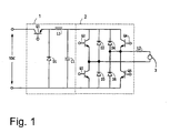
- Figure 1 shows a schematic of the first embodiment of the arrangement of a device in accordance with the invention for operating a high pressure discharge lamp
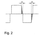
- Figure 2 is a plot of the current which flows during the dead time in a discharge lamp
- Figure 3 is a schematic of the second embodiment of the arrangement of a device in accordance with the invention for operating a high pressure discharge lamp
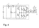
- Figure 4 is a schematic of the third embodiment of the arrangement of a device in accordance with the invention for operating a high pressure discharge lamp
- Figure 5 shows a schematic of one example of the arrangement of a known device for operating a discharge lamp.
- FIG. 1 shows the first embodiment of the arrangement of a device in accordance with the invention for operating a high pressure discharge lamp in which a DC voltage is supplied to a voltage reduction chopper circuit 1, and a high pressure discharge lamp 3 (hereinafter called a discharge lamp 3) is connected to the output side of the voltage reduction chopper circuit 1 via an invertor circuit of a full bridge system 2 (hereinafter called a full bridge circuit 2) which converts the DC voltage into an AC voltage with rectangular waves and supplies it to an inductance L2 which is series connected to the discharge lamp 3.
- a full bridge circuit 2 which converts the DC voltage into an AC voltage with rectangular waves and supplies it to an inductance L2 which is series connected to the discharge lamp 3.
- an ignition coil device is series-connected to the above described discharge lamp 3 in order to apply a high voltage pulse to the discharge lamp 3 when the lamp starts.
- the ignition coil device is not shown in Figure 1.
- the above described discharge lamp 3 is, for example, an ultra-high pressure discharge lamp of the short arc type which, as was described above, is used as the light source of a projector device of the projection type or the like.
- the discharge lamp described below can be used:
- the voltage reduction chopper circuit 1 is comprised of a switching device Q1, a diode D1, an inductance L1 and a smoothing capacitor C1.
- a control circuit (not shown) controls the ON/OFF ratio of the switching device Q1 and controls the current or wattage which is supplied to the discharge lamp 3 via the full bridge circuit 2.
- the full bridge circuit 2 is comprised of switching devices Q2 to Q5 which are connected in a bridge-like manner and which are formed of transistors, like FETs or the like, and of diodes D2, D5 which are connected antiparallel to these switching devices Q2 to Q5.
- the switching devices Q2 to Q5 are driven by a driver circuit (not shown), the discharge lamp is supplied with an alternating current with rectangular waves, and the discharge lamp 3 is operated.
- the frequency of the output alternating rectangular waves which are supplied to the discharge lamp 3 is in the range from 60 Hz to 1000 Hz, for example, 200 Hz.
- the above described dead time is normally in the range from 0.5 ⁇ s to 10 ⁇ s.
- a dead time of, for example, about 1 ⁇ s is selected.
- inductance element inductance element which is series-connected to the discharge lamp 3.
- FIG 2 schematically shows the current which flows during the above described dead time in the discharge lamp.
- Td indicates the dead time in which the energy stored in the inductance L2, with the above described loop, current is allowed to flow, as is shown using the broken lines in Figure 2.
- the amount of energy stored in the inductance L2 must be at least equal to the area of the regions which are shown cross-hatched in Figure 2.
- the energy stored in the inductance L2 is determined by the relationship: 1/2 x LL x IL 2 Td is the above described dead time (seconds), and LL is the size of the inductance L2 (H).
- VL (V) is the magnitude of the above described voltage with rectangular waves (the voltage which is applied to the discharge lamp is called the luminous voltage)
- IL (A) is the current flowing in the discharge lamp 3.
- the energy of the above described cross-hatched regions is 1/2 x W x Td.
- the value of the inductance L2 is in the range from 20 ⁇ H to 600 pH, for example, roughly 300 pH.
- the value of the inductance L2 can be chosen such that the sum of the value of the inductive reactance of the inductance L2 and the value of the inductive reactance of the ignition coil device has the above described value.
- the energy stored in the inductance L2 flows via the smoothing capacitor C1 with the above described loop and is charged in the smoothing capacitor C1. It is therefore desirable for the value of the smoothing capacitor C1 to be fixed at greater than or equal to 0.1 ⁇ F, preferably in the range from 0.2 ⁇ F to 1 ⁇ F, in order to suppress the voltage increase of the smoothing capacitor C1.
- the inductance L2 and the discharge lamp 3 are series-connected, and the value of the inductance L2 is chosen such that LL ⁇ VL/IL x Td. In this way, during the dead time, by the energy stored in the inductance L2 current can be allowed to flow in the discharge lamp 3 and extinction of the discharge lamp 3 can be prevented.
- the value of the inductance L2 is also roughly 20 ⁇ H to 600 pH, as was described above. Since it is not necessary, as in the above described known example (Japanese patent specification HEI 6-101388, U.S. Patent 4,734,624) to use an inductance L and a capacitor C with a high capacitance the rising and falling of the alternating rectangular waves which are output by the full bridge circuit can be made steep. The above described disadvantage of momentary darkening of the discharge lamp never occurs.
- FIG. 3 shows a second embodiment of the invention.
- the inductance of the ignition coil transformer of the ignition coil device which is series-connected to the discharge lamp 3 is used as an inductance which stores the energy which is used for current to flow during the dead time in the discharge lamp 3.
- an ignition coil transformer TrI of the ignition coil device 4 is series-connected to the discharge lamp 3. Furthermore, a bypass capacitor Cp1 for bridging the high voltage pulse produced by the ignition coil device 4 is connected parallel to the discharge lamp 3 and to the series connection of the ignition coil transformer TrI.
- the value of the inductance of the ignition coil transformer TrI is chosen to be a value which meets condition LL ⁇ VL/IL x Td.
- the operation of the circuit in this embodiment is identical to that in the first embodiment.
- the switching devices Q2 to Q5 of the full bridge circuit 2 are driven by a driver circuit (not shown), the discharge lamp 3 is supplied with an alternating current with rectangular waves and the discharge lamp 3 is operated.
- the value of the inductance of the ignition coil transformer TrI is 20 ⁇ H to 600 pH, as was described in the first embodiment. Therefore, the rise and fall of the alternating rectangular waves which are output to the full bridge circuit can be made steep. The above described disadvantage of instantaneous darkening of the discharge lamp never occurs.
- bypass capacitor Cp1 Since it is sufficient for the above described bypass capacitor Cp1 to work in such a way that it bridges the high voltage pulse produced by the ignition coil device 4, its capacitance value can be at most equal to 4000 pF, preferably roughly 1000 pF to 2000 pF.
- Figure 4 shows a third embodiment of the invention.
- this embodiment on the output side of the full bridge circuit 2, there is a reactance with common mode L3. In this way, damage to the electronic parts, like the full bridge circuit and the like, by the high voltage pulse of the ignition coil device is prevented.
- FIG 4 shows the same parts as in Figure 3 with the same reference numbers as in Figure 3.
- the inductance of the ignition coil transformer 4a of the ignition coil device is used as an inductance which stores the energy which is used for current to flow during the dead time in the discharge lamp 3.
- the inductive reactance value of the ignition coil transformer 4a is chosen to be a value which meets condition LL ⁇ VL/IL x Td.
- the reactance with common mode L3 which blocks passage of the high voltage pulse of the ignition coil device, and the bypass capacitors Cp1 and Cp2 for bridging this high voltage pulse are connected to the output side of the full bridge circuit 2.
- the operation of the circuit in this embodiment is identical to that in the second embodiment.
- the switching devices Q2 to Q5 of the full bridge circuit 2 are driven by a driver circuit which is not shown in the drawings, the discharge lamp 3 is supplied with an alternating current with rectangular waves, and thus the discharge lamp 3 is operated.
- bypass capacitors Cp1 and Cp2 have a relatively small capacitance, as in the third embodiment, the effect on the rising and falling of the rectangular AC voltage is low. The disadvantage of instantaneous darkening of the discharge lamp never occurs.
- the device in accordance with the invention for operating a high pressure discharge lamp which is used as the light source of a projector of the projection type, it is possible to improve the image quality of the projector.
Applications Claiming Priority (2)
| Application Number | Priority Date | Filing Date | Title |
|---|---|---|---|
| JP2002193501A JP2004039390A (ja) | 2002-07-02 | 2002-07-02 | 高圧放電ランプ点灯装置 |
| JP2002193501 | 2002-07-02 |
Publications (1)
| Publication Number | Publication Date |
|---|---|
| EP1379110A1 true EP1379110A1 (en) | 2004-01-07 |
Family
ID=29720253
Family Applications (1)
| Application Number | Title | Priority Date | Filing Date |
|---|---|---|---|
| EP03014115A Withdrawn EP1379110A1 (en) | 2002-07-02 | 2003-06-23 | Device for operating a high pressure discharge lamp |
Country Status (4)
| Country | Link |
|---|---|
| US (1) | US6815910B2 (ja) |
| EP (1) | EP1379110A1 (ja) |
| JP (1) | JP2004039390A (ja) |
| CN (1) | CN1476285A (ja) |
Families Citing this family (11)
| Publication number | Priority date | Publication date | Assignee | Title |
|---|---|---|---|---|
| WO2002031967A2 (en) | 2000-10-10 | 2002-04-18 | California Institute Of Technology | Distributed circular geometry power amplifier architecture |
| US6856199B2 (en) * | 2000-10-10 | 2005-02-15 | California Institute Of Technology | Reconfigurable distributed active transformers |
| TWI326967B (en) * | 2002-03-11 | 2010-07-01 | California Inst Of Techn | Differential amplifier |
| WO2005032219A1 (en) * | 2003-09-26 | 2005-04-07 | Vicious Power Pty Ltd | Arc lamp improvements |
| DE102005023171A1 (de) * | 2004-05-28 | 2005-12-22 | Harison Toshiba Lighting Corp. | Lichtvorrichtung für Entladungslampen |
| WO2006051540A2 (en) * | 2004-11-10 | 2006-05-18 | Alexander Mostovoy | A method and device for transforming and regulating a voltage signal |
| EP1897418A2 (en) * | 2005-06-21 | 2008-03-12 | Koninklijke Philips Electronics N.V. | Method for driving an inverter of a gas discharge supply circuit |
| JP4710754B2 (ja) * | 2006-02-13 | 2011-06-29 | ウシオ電機株式会社 | 放電ランプ点灯装置 |
| US7710197B2 (en) | 2007-07-11 | 2010-05-04 | Axiom Microdevices, Inc. | Low offset envelope detector and method of use |
| US10482004B2 (en) * | 2015-10-16 | 2019-11-19 | Successfactors, Inc. | Test data framework |
| CN110383167B (zh) * | 2017-02-27 | 2022-08-23 | Hoya株式会社 | 掩模坯料、转印用掩模的制造方法、以及半导体器件的制造方法 |
Citations (4)
| Publication number | Priority date | Publication date | Assignee | Title |
|---|---|---|---|---|
| US4734624A (en) * | 1985-07-25 | 1988-03-29 | Matsushita Electric Works, Ltd. | Discharge lamp driving circuit |
| US5434474A (en) * | 1993-04-12 | 1995-07-18 | Mitsubishi Denki Kabushiki Kaisha | Lighting apparatus for discharge lamp |
| US5514935A (en) * | 1993-01-07 | 1996-05-07 | Koito Manufacturing Co., Ltd. | Lighting circuit for vehicular discharge lamp |
| US5565743A (en) * | 1994-08-30 | 1996-10-15 | Koito Manufacturing Co., Ltd. | Lighting circuit for discharge lamp |
Family Cites Families (5)
| Publication number | Priority date | Publication date | Assignee | Title |
|---|---|---|---|---|
| GB2172451B (en) * | 1985-02-07 | 1989-06-14 | El Co Villamos Keszulekek Es S | Circuit system for igniting and lighting a high-pressure discharge lamp particulary a sodium vapour lamp |
| EP0314077B1 (en) * | 1987-10-27 | 1994-01-26 | Matsushita Electric Works, Ltd. | Discharge lamp driving circuit |
| DE4437453A1 (de) * | 1994-10-19 | 1996-04-25 | Patent Treuhand Ges Fuer Elektrische Gluehlampen Mbh | Verfahren zum Betrieb einer Entladungslampe und Schaltungsanordnung zum Betrieb einer Entladungslampe |
| EP0858724B1 (en) * | 1996-09-05 | 2003-03-12 | Koninklijke Philips Electronics N.V. | Circuit arrangement |
| BR9913860A (pt) * | 1998-09-18 | 2001-06-12 | Knobel Lichttech | Organização de circuito para operação de lâmpadas de descarga gasosa |
-
2002
- 2002-07-02 JP JP2002193501A patent/JP2004039390A/ja active Pending
-
2003
- 2003-06-23 EP EP03014115A patent/EP1379110A1/en not_active Withdrawn
- 2003-06-25 US US10/602,917 patent/US6815910B2/en not_active Expired - Lifetime
- 2003-07-02 CN CNA031481388A patent/CN1476285A/zh active Pending
Patent Citations (4)
| Publication number | Priority date | Publication date | Assignee | Title |
|---|---|---|---|---|
| US4734624A (en) * | 1985-07-25 | 1988-03-29 | Matsushita Electric Works, Ltd. | Discharge lamp driving circuit |
| US5514935A (en) * | 1993-01-07 | 1996-05-07 | Koito Manufacturing Co., Ltd. | Lighting circuit for vehicular discharge lamp |
| US5434474A (en) * | 1993-04-12 | 1995-07-18 | Mitsubishi Denki Kabushiki Kaisha | Lighting apparatus for discharge lamp |
| US5565743A (en) * | 1994-08-30 | 1996-10-15 | Koito Manufacturing Co., Ltd. | Lighting circuit for discharge lamp |
Also Published As
| Publication number | Publication date |
|---|---|
| JP2004039390A (ja) | 2004-02-05 |
| CN1476285A (zh) | 2004-02-18 |
| US20040004449A1 (en) | 2004-01-08 |
| US6815910B2 (en) | 2004-11-09 |
Similar Documents
| Publication | Publication Date | Title |
|---|---|---|
| KR100671524B1 (ko) | 고휘도 방전 램프용 조도조절 가능한 전자 안정기 | |
| EP1379112B1 (en) | Device for operating a high pressure discharge lamp | |
| EP0910229A2 (en) | Cold-cathode tube lighting circuit with protection circuit for piezoelectric transformer | |
| US6815910B2 (en) | Device for operating a high pressure discharge lamp | |
| JPH07230884A (ja) | 高圧放電灯点灯装置 | |
| US7242153B2 (en) | Pulse width modulation inverter circuit and control method thereof | |
| US6570347B2 (en) | Gas-discharge lamp having brightness control | |
| EP1464209B1 (en) | Electronic circuit, and method of operating a high-pressure lamp | |
| US6876158B2 (en) | Electronic ballast with full bridge circuit | |
| US20100052561A1 (en) | Method for driving an inverter of a gas discharge supply circuit | |
| JPH09237684A (ja) | インバータ回路 | |
| JP3541644B2 (ja) | バックライト制御装置 | |
| US5945787A (en) | Power control of an AC-operated high-pressure gas discharge lamp, particularly for motor vehicles | |
| JP4239356B2 (ja) | 放電灯点灯装置 | |
| KR940001188B1 (ko) | 고압 방전관용 전자식 안정화 장치 | |
| JPH05501477A (ja) | 蛍光管を加熱し始動させる回路 | |
| JP2009517826A (ja) | ガス放電ランプの操作システム及び方法、並びに当該システムの使用方法 | |
| KR100711812B1 (ko) | Hid용 무접점 전자제어 고압제어 안정기 | |
| JP3571126B2 (ja) | 放電灯点灯装置 | |
| JP4008373B2 (ja) | 放電灯点灯装置 | |
| JP5547907B2 (ja) | 放電灯点灯装置及びそれを用いた車載用前照灯点灯装置 | |
| JP4608804B2 (ja) | 無電極放電灯点灯装置 | |
| JPH1075576A (ja) | 圧電トランスの制御回路 | |
| JP2006120502A (ja) | 高圧放電灯点灯装置 | |
| JP2007087821A (ja) | 高圧放電ランプ点灯装置及び照明装置 |
Legal Events
| Date | Code | Title | Description |
|---|---|---|---|
| PUAI | Public reference made under article 153(3) epc to a published international application that has entered the european phase |
Free format text: ORIGINAL CODE: 0009012 |
|
| 17P | Request for examination filed |
Effective date: 20031002 |
|
| AK | Designated contracting states |
Kind code of ref document: A1 Designated state(s): AT BE BG CH CY CZ DE DK EE ES FI FR GB GR HU IE IT LI LU MC NL PT RO SE SI SK TR |
|
| AX | Request for extension of the european patent |
Extension state: AL LT LV MK |
|
| AKX | Designation fees paid |
Designated state(s): DE GB NL |
|
| 17Q | First examination report despatched |
Effective date: 20050727 |
|
| STAA | Information on the status of an ep patent application or granted ep patent |
Free format text: STATUS: THE APPLICATION IS DEEMED TO BE WITHDRAWN |
|
| 18D | Application deemed to be withdrawn |
Effective date: 20081028 |