EP1378621A1 - Mécanisme d'embrayage pour la commande d'une serrure, et porte le comportant - Google Patents
Mécanisme d'embrayage pour la commande d'une serrure, et porte le comportant Download PDFInfo
- Publication number
- EP1378621A1 EP1378621A1 EP03291599A EP03291599A EP1378621A1 EP 1378621 A1 EP1378621 A1 EP 1378621A1 EP 03291599 A EP03291599 A EP 03291599A EP 03291599 A EP03291599 A EP 03291599A EP 1378621 A1 EP1378621 A1 EP 1378621A1
- Authority
- EP
- European Patent Office
- Prior art keywords
- hub
- external
- rotation
- key
- lock
- Prior art date
- Legal status (The legal status is an assumption and is not a legal conclusion. Google has not performed a legal analysis and makes no representation as to the accuracy of the status listed.)
- Granted
Links
- 230000007246 mechanism Effects 0.000 title claims abstract description 47
- 238000006073 displacement reaction Methods 0.000 claims abstract description 27
- 238000013475 authorization Methods 0.000 claims description 28
- 230000000903 blocking effect Effects 0.000 claims description 20
- 210000000056 organ Anatomy 0.000 description 4
- 230000009471 action Effects 0.000 description 2
- 240000008042 Zea mays Species 0.000 description 1
- 230000008859 change Effects 0.000 description 1
- 230000000694 effects Effects 0.000 description 1
Images


Classifications
-
- E—FIXED CONSTRUCTIONS
- E05—LOCKS; KEYS; WINDOW OR DOOR FITTINGS; SAFES
- E05B—LOCKS; ACCESSORIES THEREFOR; HANDCUFFS
- E05B47/00—Operating or controlling locks or other fastening devices by electric or magnetic means
- E05B47/06—Controlling mechanically-operated bolts by electro-magnetically-operated detents
- E05B47/0676—Controlling mechanically-operated bolts by electro-magnetically-operated detents by disconnecting the handle
- E05B47/0684—Controlling mechanically-operated bolts by electro-magnetically-operated detents by disconnecting the handle radially
- E05B47/0692—Controlling mechanically-operated bolts by electro-magnetically-operated detents by disconnecting the handle radially with a rectilinearly moveable coupling element
-
- E—FIXED CONSTRUCTIONS
- E05—LOCKS; KEYS; WINDOW OR DOOR FITTINGS; SAFES
- E05B—LOCKS; ACCESSORIES THEREFOR; HANDCUFFS
- E05B63/00—Locks or fastenings with special structural characteristics
- E05B63/16—Locks or fastenings with special structural characteristics with the handles on opposite sides moving independently
Definitions
- the present invention relates to a clutch mechanism intended for controlling a lock, more specifically intended to secure the internal and external handles of ordering a lock.
- Such a clutch mechanism is particularly useful in cooperation with a movement authorization mechanism of a control member or handle by composition of a code, and the invention is described in this application.
- the doors are often fitted with a lock which has a key system to lock the door.
- a lock which has a key system to lock the door.
- anyone can enter the room served by the door. So we already have produced devices for composing a code intended for allow or prohibit the opening of a door, for example at the entrance of a building.
- the exterior handle of the lock is generally blocked when the device dialing a code prohibits opening the door.
- the dialing device of a code we sometimes incorporated a limiting device efforts allowing the rotation of the external handle, but without control of the lock.
- control devices lock associated with code dialing devices only work in one direction, that is, it is necessary to produce two different locks for the command to the right or to the left, or at least to invert elements of the lock depending on whether the order must be performed left or right.
- the subject of the invention is a clutch mechanism intended to ensure the connection between a composition device a code and a lock, which can be used even with locks with three locking points, without change depending on whether the command is on the right or on the left, and with devices composing a type code electric as well as mechanical.
- the invention relates to a mechanism clutch for controlling a lock, acting between an inner hub and an outer hub which can turn each one separately, around a common axis, one operating angle of a lock from a position of rest, the internal hub can still control the lock associated by rotation of the operating angle, then the external hub cannot control the associated lock when secured to the internal hub by the clutch mechanism, each hub being returned to its rest position by an elastic return device hub;
- the mechanism comprises a key driven in rotation by a first of the hubs internal and external and which, within an angular range of authorization of the outer hub, starting at the rest position of the external hub and of amplitude less than the angle of maneuver, is movable in translation relative to the first hubs between a keying position in which it transmits the rotation from the outer hub to the inner hub in part of the operating range, and a position of free rotation in which it does not transmit the rotation of the outer hub to the inner hub, a device elastic to return the key to its position keying, and a locking member which, when
- the angular range of authorization is less than half of the lock operating range.
- the operating range is around 45 ° and the authorization range of around 15 °.
- the external hub controls the displacement in translation of a displacement member in direction perpendicular to the common axis.
- the displacement member is connected to the blocking member by a limiter of effort so that the displacement organ, which is always moved by the rotation of the outer hub, does not cause the displacement of the blocking member only when it is not held in the locked position.
- the displacement member is moved by the external hub by cooperation of a cam member of the external hub with a surface of the displacement member.
- the key is movable along an axis perpendicular to the common axis of rotation.
- the key in its free rotation position, is entirely contained in the external volume delimited by the first of the inner and outer hubs and is only visible on the side of the blocking member.
- the external hub has a cylindrical guide cavity
- the internal hub has a projecting cylinder guided in rotation in the cavity of the outer hub around the common axis and having at its periphery, on the side opposite to the blocking member, a recess of circumferential dimension corresponding approximately to the angular range of increased authorization of the dimension of the key in the direction of this dimension circumferentially.
- the blocking is an organ of a controlled authorization mechanism by a code.
- the authorization mechanism controlled by code is a mechanism that includes a flat slide movable in translation in one direction and having lateral notches, stops each having a groove and movable in direction perpendicular to the slide flat between a slide release position in which the slide is free to move in the stop groove and a blocking position in which part of the stop other than his throat prevents the moving the slide, and accessible pushers from outside the mechanism and intended to control each a judgment, and the authorization mechanism body controlled by a code is the slide whose direction of translational movement is perpendicular to the axis common.
- the hub external and the internal hub on the side of cooperation with the key, have symmetry with respect to a plane containing the common axis and the key in the position of hub rest.
- the blocking member is at key contact on both sides of the vertical plane of symmetry.
- the invention also relates to a door provided with a lock with three locking points, the control of which by rotating a handle in the first direction causes the opening of the lock, and the control by rotation of a handle in the opposite direction causes the lock to minus two of the three locking points.
- the lock is associated with an authorization mechanism controlled by a code to which it is connected by a mechanism clutch according to the previous paragraphs.
- FIG. 1 shows in exploded schematic form and simplified the main elements of a mechanism clutch according to the invention.
- An internal hub 10 cooperates with an external hub 12 via a key 14 the position of which can be determined by a blocking 16, belonging to a composition control device a code, which can be moved by a body of displacement 18 controlled by the external hub 12 and connected to the blocking member 16 by a force limiter schematically represented by spring 20.
- the internal hub 10 which has a rod 22, which can be a lock control square, is intended to directly control a door lock.
- the inner hub 10 has a cylindrical projection delimiting a space 26.
- the projection 24 actually has the shape of two arcs of circle centered on the axis of rotation of the inner hub 10. This axis of rotation is common for the internal hubs 10 and external 12.
- the cylindrical projection 24 can rotate freely at the interior of a cylinder 28 which delimits a cylindrical cavity 30 guide in the hub 12.
- the axes of the cylinder 28 and the cavity 30 are merged with the common axis of rotation of the two hubs 10 and 12.
- the outer hub 12 can be associated with a handle by a rod 34 which can be a classic square.
- the cylindrical projection 28 has a diametrical groove 32 intended to accommodate the key 14.
- the key 14 has two grooves 40, 42 (which can form only one groove continuous) in which are intended to turn the two parts in an arc of the projection 24 when the key is held in the outer hub 10 in a central position.
- the parts in an arc of the projection 24 do not cannot pass through grooves 40 and 42 so that a rotation of the outer hub 12 causes the hub to rotate internal 10.
- the external hub 12 has cams 36 which, when the hub 12 rotates, displaces a member 18 of displacement which, via a limiter effort, can move the locking member 16 itself.
- the blocking member 16 is normally in a sufficiently low position to maintain the key 14 in its centered position in which the hub external and the internal hub can rotate freely one compared to each other.
- the blocking member 16 can be moved away from the key (upwards on the figure 1) under the action of the force exerted by the intermediary of the displacement member 18, the key can be decenter and secure the two hubs.
- the two parts in an arc of the projection 24 are separated by an angular space corresponding to a range angular authorization increased by the width of the key 14.
- the external hub 12 begins to turn under the action of a force applied to a handle, its cam 36 causes an uplift of the organ 18. If the member 16 is blocked, the key 14 cannot be move, so that when the rotation of the outer hub 12 continues, the parts in an arc of the projection 24 are housed in the grooves 40 and 42 of the key, if although the key can rotate freely relative to the internal hub 10. It is therefore not driven and the associated door lock is not ordered.
- the key 14 which is always recalled upwards by a spring (not shown in Figure 1) goes up, so that the parts in arc of the projection 24 come up against the key 14 instead of entering the grooves 40, 42.
- the key 14 therefore secures the two hubs 10 in rotation and 12, and the continued rotation of the hub 12 causes the rotational drive of the internal hub 10.
- range angular of authorization there is a first range angular rotation of the outer hub, called “range angular of authorization "in which the blocking member 16 can be moved aside and the key 14 can then move in the angular space cleared between the arcuate parts of protrusion circle 24.
- range angular of authorization which can be of the order of 15 °
- the hub 12 can drive the hub internal 10, with an angular offset between the two which corresponds to this angular range of authorization. It is necessary therefore that the residual rotation of the operating member 12 allows sufficient rotation of the inner hub 10 to order the associated lock.
- the total range of operation of the external hub 12 is for example 45 °
- the internal hub 10 is driven by 30 °, sufficient value normally for controlling the associated lock. if it is preferable that the operating angle of the lock associated be larger, of course, the angle of maneuver of the outer hub 12 is increased by the same amount.
- Figure 2 is a section of a device made according to the principle illustrated in figure 1.
- Figures 3A to 3C show the operation of a such mechanism in the authorization range.
- the displacement 18 is in abutment against the cams 36 of the hub external and the blocking member 16 is practically in abutment against the key 14 in the central position.
- the displacement 18 is lifted by a cam 36, but it does not drive the blocking member 16 since it is held in position by the authorization mechanism. In Consequently, the key keeps its central position.
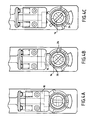
- Figures 4A to 4C show the relative positions when the outer handle is turned 45 °.
- the figure 4A corresponds to FIG. 3A.
- Figure 4B indicates that the greater displacement of the displacement member 18 by the cam 36 of the external hub has still not caused any displacement of the locking member 16. Consequently, the cam 14 is rotated by the external hub without drive the internal hub.
- the code dialing device allows the movement of the locking member
- the key 14 which has moved towards the exterior as shown in Figure 3C, is in contact with the side of the part in an arc of the projection 24, and it therefore drives the internal hub 10 when the hub external 12 is rotated.
- Cam 36 in moving organ 18, also causes displacement of the blocking member 16 which thus allows the opening of the associated lock.
- FIGS. 3B, 3C, 4B and 4C are symmetrical about a vertical plane and give strictly the same effect in both directions. The same device can therefore be used for control by right or left maneuver. This characteristic is particularly important in the case of three-way locks locking points.
- the one-way rotation of the lock control rod causes the bolt to be controlled, and the rotation in the other sense causes the locking of the different points of locking.
- the authorization mechanism for the control of the lock works both in one direction and in the other. It is therefore possible either to prohibit simultaneously the control of the lock and the locking of the different points, either to authorize them simultaneously
- the blocking member is a slide of a device authorization to maneuver by dialing a code
- the blocking member can be of any type, not only controlled mechanically but also electrically.
Landscapes
- Engineering & Computer Science (AREA)
- Structural Engineering (AREA)
- Lock And Its Accessories (AREA)
Abstract
Description
Claims (10)
- Mécanisme d'embrayage destiné à la commande d'une serrure, agissant entre un moyeu interne (10) et un moyeu externe (12) qui peuvent tourner chacun séparément, autour d'un axe commun, d'un angle de manoeuvre d'une serrure depuis une position de repos,
le moyeu interne (10) pouvant toujours commander la serrure associée par rotation de l'angle de manoeuvre, alors que le moyeu externe (12) ne peut commander la serrure associée que lorsqu'il est solidarisé au moyeu interne (10) par le mécanisme d'embrayage,
chaque moyeu étant rappelé vers sa position de repos par un dispositif élastique de rappel de moyeu,
caractérisé en ce qu'il comprend
une clavette (14) entraínée en rotation par un premier des moyeux interne et externe (10, 12) et qui, dans une plage angulaire d'autorisation du moyeu externe (12), commençant à la position de repos du moyeu externe (12) et d'amplitude inférieure à l'angle de manoeuvre, est mobile en translation par rapport au premier des moyeux (10, 12) entre une position de clavetage dans laquelle elle transmet la rotation du moyeu externe (12) au moyeu interne (10) dans une partie de la plage de manoeuvre, et une position de rotation libre dans laquelle elle ne transmet pas la rotation du moyeu externe (12) au moyeu interne (10),
un dispositif élastique de rappel de la clavette (14) vers sa position de clavetage, et
un organe (16) de blocage qui, lorsqu'il est maintenu dans une position de blocage, interdit le déplacement en translation de la clavette (14) par rapport au premier des moyeux interne et externe (10, 12), dans la plage angulaire d'autorisation du moyeu externe (12). - Mécanisme selon la revendication 1, caractérisé en ce que le moyeu externe (12) commande le déplacement en translation d'un organe (18) de déplacement en direction perpendiculaire à l'axe commun.
- Mécanisme selon la revendication 2, caractérisé en ce que l'organe de déplacement est raccordé à l'organe de blocage par un limiteur d'effort afin que l'organe de déplacement, qui est toujours déplacé par la rotation du moyeu externe (12), ne provoque le déplacement de l'organe de blocage que lorsque celui-ci n'est pas maintenu en position de blocage.
- Mécanisme selon la revendication 3, caractérisé en ce que l'organe de déplacement est déplacé par le moyeu externe (12) par coopération d'un organe de came (36) du moyeu externe (12) avec une surface de l'organe de déplacement.
- Mécanisme selon l'une quelconque des revendications précédentes, caractérisé en ce que dans sa position de rotation libre, la clavette (14) est entièrement contenue dans le volume extérieur délimité par le premier des moyeux interne et externe (10, 12) et n'est apparente que du côté de l'organe de blocage.
- Mécanisme selon la revendication 5, caractérisé en ce que le moyeu externe (12) possède une cavité cylindrique (30) de guidage, le moyeu interne (10) possède un cylindre en saillie (24) guidé en rotation dans la cavité du moyeu externe (12) autour de l'axe commun et ayant à sa périphérie, du côté opposé à l'organe de blocage, un évidement de dimension circonférentielle correspondant approximativement à la plage angulaire d'autorisation augmentée de la dimension de la clavette (14) dans la direction de cette dimension circonférentielle.
- Mécanisme selon l'une quelconque des revendications précédentes, caractérisé en ce que l'organe de blocage est un organe d'un mécanisme d'autorisation commandé par un code.
- Mécanisme selon la revendication 7, dans lequel le mécanisme d'autorisation commandé par un code est un mécanisme qui comprend un coulisseau plat mobile en translation dans une direction et ayant des encoches latérales, des arrêts ayant chacun une gorge et mobiles en direction perpendiculaire au coulisseau plat entre une position de libération de coulisseau dans laquelle le coulisseau est libre de se déplacer dans la gorge de l'arrêt et une position de blocage dans laquelle une partie de l'arrêt autre que sa gorge empêche le déplacement du coulisseau, et des poussoirs accessibles depuis l'extérieur du mécanisme et destinés à commander chacun un arrêt, caractérisé en ce que ledit organe de mécanisme d'autorisation commandé par un code est le coulisseau dont la direction de déplacement en translation est perpendiculaire à l'axe commun.
- Mécanisme selon l'une quelconque des revendications précédentes, caractérisé en ce que le moyeu externe (12) et le moyeu interne (10), du côté de coopération avec la clavette (14), présentent une symétrie par rapport à un plan contenant l'axe commun et la clavette (14) dans la position de repos des moyeux.
- Porte munie d'une serrure à trois points de verrouillage, dont la commande par rotation d'une poignée dans un premier sens provoque l'ouverture de la serrure, et la commande par rotation d'une poignée dans le sens opposé provoque le verrouillage d'au moins deux des trois points de verrouillage, caractérisée en ce que la serrure est associée à un mécanisme d'autorisation commandé par un code auquel elle est raccordée par un mécanisme d'embrayage selon l'une quelconque des revendications précédentes.
Applications Claiming Priority (2)
| Application Number | Priority Date | Filing Date | Title |
|---|---|---|---|
| FR0208220A FR2841583B1 (fr) | 2002-07-01 | 2002-07-01 | Mecanisme d'embrayage pour la commande d'une serrure, et porte le comportant |
| FR0208220 | 2002-07-01 |
Publications (3)
| Publication Number | Publication Date |
|---|---|
| EP1378621A1 true EP1378621A1 (fr) | 2004-01-07 |
| EP1378621A8 EP1378621A8 (fr) | 2004-08-11 |
| EP1378621B1 EP1378621B1 (fr) | 2006-07-26 |
Family
ID=29720066
Family Applications (1)
| Application Number | Title | Priority Date | Filing Date |
|---|---|---|---|
| EP20030291599 Expired - Lifetime EP1378621B1 (fr) | 2002-07-01 | 2003-06-27 | Mécanisme d'embrayage pour la commande d'une serrure, et porte le comportant |
Country Status (4)
| Country | Link |
|---|---|
| EP (1) | EP1378621B1 (fr) |
| DE (1) | DE60306996T2 (fr) |
| ES (1) | ES2269945T3 (fr) |
| FR (1) | FR2841583B1 (fr) |
Cited By (2)
| Publication number | Priority date | Publication date | Assignee | Title |
|---|---|---|---|---|
| CN108343324A (zh) * | 2018-04-18 | 2018-07-31 | 李祥龙 | 一种用于智能锁的力偶矩模式离合机构及其锁芯组件 |
| WO2019071307A1 (fr) * | 2017-10-10 | 2019-04-18 | Assa Abloy Australia Pty Limited | Ensemble serrure électronique |
Families Citing this family (1)
| Publication number | Priority date | Publication date | Assignee | Title |
|---|---|---|---|---|
| GB2448527A (en) * | 2007-04-18 | 2008-10-22 | Pbt | Electronically controlled clutch arrangement for a locking mechanism comprising cams, actuator and sliding member |
Citations (5)
| Publication number | Priority date | Publication date | Assignee | Title |
|---|---|---|---|---|
| EP0438008A1 (fr) * | 1990-01-19 | 1991-07-24 | FERCO INTERNATIONAL Usine de Ferrures de BÀ¢timent Société à responsabilité limitée | Crémone-serrure pour porte, fenêtre ou analogue |
| DE19607765A1 (de) * | 1996-03-01 | 1999-08-12 | Messerschmitt Systems Gmbh | Vorrichtung zum Betätigen eines Schlosses, insbesondere eines über eine Kontrolleinrichtung zu sichernden Schlosses |
| EP1030011A1 (fr) * | 1999-02-18 | 2000-08-23 | Etablissements Decayeux | Dispositif d'embrayage d'une béquille extérieure de serrure avec son pêne mobile |
| EP1098053A2 (fr) * | 1999-11-03 | 2001-05-09 | Kaba Gege GmbH | Mandrin fendu |
| EP1113130A1 (fr) * | 1999-12-31 | 2001-07-04 | Escudos Kala Internacional S.L. | Dispositif d' embrayage pour verrous électroniques |
-
2002
- 2002-07-01 FR FR0208220A patent/FR2841583B1/fr not_active Expired - Fee Related
-
2003
- 2003-06-27 DE DE2003606996 patent/DE60306996T2/de not_active Expired - Lifetime
- 2003-06-27 EP EP20030291599 patent/EP1378621B1/fr not_active Expired - Lifetime
- 2003-06-27 ES ES03291599T patent/ES2269945T3/es not_active Expired - Lifetime
Patent Citations (5)
| Publication number | Priority date | Publication date | Assignee | Title |
|---|---|---|---|---|
| EP0438008A1 (fr) * | 1990-01-19 | 1991-07-24 | FERCO INTERNATIONAL Usine de Ferrures de BÀ¢timent Société à responsabilité limitée | Crémone-serrure pour porte, fenêtre ou analogue |
| DE19607765A1 (de) * | 1996-03-01 | 1999-08-12 | Messerschmitt Systems Gmbh | Vorrichtung zum Betätigen eines Schlosses, insbesondere eines über eine Kontrolleinrichtung zu sichernden Schlosses |
| EP1030011A1 (fr) * | 1999-02-18 | 2000-08-23 | Etablissements Decayeux | Dispositif d'embrayage d'une béquille extérieure de serrure avec son pêne mobile |
| EP1098053A2 (fr) * | 1999-11-03 | 2001-05-09 | Kaba Gege GmbH | Mandrin fendu |
| EP1113130A1 (fr) * | 1999-12-31 | 2001-07-04 | Escudos Kala Internacional S.L. | Dispositif d' embrayage pour verrous électroniques |
Cited By (3)
| Publication number | Priority date | Publication date | Assignee | Title |
|---|---|---|---|---|
| WO2019071307A1 (fr) * | 2017-10-10 | 2019-04-18 | Assa Abloy Australia Pty Limited | Ensemble serrure électronique |
| AU2018347006B2 (en) * | 2017-10-10 | 2024-11-07 | Assa Abloy Australia Pty Limited | Electronic lockset |
| CN108343324A (zh) * | 2018-04-18 | 2018-07-31 | 李祥龙 | 一种用于智能锁的力偶矩模式离合机构及其锁芯组件 |
Also Published As
| Publication number | Publication date |
|---|---|
| EP1378621B1 (fr) | 2006-07-26 |
| DE60306996T2 (de) | 2007-02-22 |
| EP1378621A8 (fr) | 2004-08-11 |
| DE60306996D1 (de) | 2006-09-07 |
| FR2841583A1 (fr) | 2004-01-02 |
| ES2269945T3 (es) | 2007-04-01 |
| FR2841583B1 (fr) | 2004-12-10 |
Similar Documents
| Publication | Publication Date | Title |
|---|---|---|
| EP0896118A1 (fr) | Serrure de porte de vehicule automobile a condamnation electrique | |
| WO2005106908A1 (fr) | Bouton rotatif pour circuit electrique | |
| EP1378621B1 (fr) | Mécanisme d'embrayage pour la commande d'une serrure, et porte le comportant | |
| FR2860261A1 (fr) | Dispositif de fermeture d'une ouverture et vehicule automobile correspondant | |
| EP1004730B1 (fr) | Serrure pour portière avant ou arrière de véhicule automobile | |
| FR2726312A1 (fr) | Dispositif d'accouplement debrayable de deux tiges coaxiales associees a des poignees d'actionnement d'une serrure | |
| EP0626494B1 (fr) | Dispositif de commande pour le verrouillage automatique d'un ouvrant de fenêtre ou analogue | |
| WO2004033832A2 (fr) | Dispositif de commande d'ouverture d'ouvrants de vehicule automobile | |
| EP0894921B1 (fr) | Dispositif de fermeture, en particulier serrure avec pene demi-tour, a encastrer dans un battant de porte-fenêtre ou analogue. | |
| EP0204605B1 (fr) | Dispositif de fixation d'un élément de serrure sur une porte de véhicule | |
| EP1041221A1 (fr) | Poignée d'ouvrant de véhicule automobile monté pivotant autour de deux axes distincts | |
| FR2697566A1 (fr) | Serrure à pêne basculant. | |
| EP0894928B1 (fr) | Dispositif de fermeture, en particulier serrure à encastrer dans un battant de porte-fenêtre ou analogue | |
| FR2789427A1 (fr) | Poignee de vehicule automobile | |
| EP0940529A1 (fr) | Cylindre de sûreté à barillet double | |
| EP4050182B1 (fr) | Dispositif de commande d'un mécanisme de verrouillage/déverrouillage d'un ouvrant | |
| WO2019077219A1 (fr) | Vehicule comprenant un dispositif de verrouillage d'ouvrant integrant la commande d'ouverture dudit ouvrant | |
| EP4321713B1 (fr) | Dispositif de verrouillage pour ouvrant d'un véhicule | |
| FR2815067A1 (fr) | Cylindre de surete a barillet prioritaire | |
| EP0880155B1 (fr) | Serrure electrique commandée par un interrupteur susceptible d'être inhibe | |
| WO1996000339A1 (fr) | Dispositif de positionnement a distance d'un mecanisme a trois positions | |
| FR2666054A1 (fr) | Dispositif pour limiter le nombre de tours de l'arbre d'une commande rotative pour toits ouvrants de vehicules automobiles. | |
| EP1619073B1 (fr) | Dispositif de bras articulé à plusieurs mouvements notamment pour l'aide à la manutention | |
| FR2801623A1 (fr) | Ouvrant de vehicule automobile avec serrure a condamnation/decondamnation electrique apte a s'ouvrir a retardement | |
| EP0869236B1 (fr) | Cylindre de sûrete manoeuvrable d'un côté quand une clef est en place de l'autre côté |
Legal Events
| Date | Code | Title | Description |
|---|---|---|---|
| PUAI | Public reference made under article 153(3) epc to a published international application that has entered the european phase |
Free format text: ORIGINAL CODE: 0009012 |
|
| AK | Designated contracting states |
Kind code of ref document: A1 Designated state(s): AT BE BG CH CY CZ DE DK EE ES FI FR GB GR HU IE IT LI LU MC NL PT RO SE SI SK TR |
|
| AX | Request for extension of the european patent |
Extension state: AL LT LV MK |
|
| 17P | Request for examination filed |
Effective date: 20040519 |
|
| AKX | Designation fees paid |
Designated state(s): DE ES GB IT |
|
| GRAP | Despatch of communication of intention to grant a patent |
Free format text: ORIGINAL CODE: EPIDOSNIGR1 |
|
| GRAS | Grant fee paid |
Free format text: ORIGINAL CODE: EPIDOSNIGR3 |
|
| GRAA | (expected) grant |
Free format text: ORIGINAL CODE: 0009210 |
|
| AK | Designated contracting states |
Kind code of ref document: B1 Designated state(s): DE ES GB IT |
|
| PG25 | Lapsed in a contracting state [announced via postgrant information from national office to epo] |
Ref country code: IT Free format text: LAPSE BECAUSE OF FAILURE TO SUBMIT A TRANSLATION OF THE DESCRIPTION OR TO PAY THE FEE WITHIN THE PRESCRIBED TIME-LIMIT;WARNING: LAPSES OF ITALIAN PATENTS WITH EFFECTIVE DATE BEFORE 2007 MAY HAVE OCCURRED AT ANY TIME BEFORE 2007. THE CORRECT EFFECTIVE DATE MAY BE DIFFERENT FROM THE ONE RECORDED. Effective date: 20060726 |
|
| REG | Reference to a national code |
Ref country code: GB Ref legal event code: FG4D Free format text: NOT ENGLISH |
|
| REF | Corresponds to: |
Ref document number: 60306996 Country of ref document: DE Date of ref document: 20060907 Kind code of ref document: P |
|
| GBT | Gb: translation of ep patent filed (gb section 77(6)(a)/1977) |
Effective date: 20061004 |
|
| REG | Reference to a national code |
Ref country code: ES Ref legal event code: FG2A Ref document number: 2269945 Country of ref document: ES Kind code of ref document: T3 |
|
| PLBE | No opposition filed within time limit |
Free format text: ORIGINAL CODE: 0009261 |
|
| STAA | Information on the status of an ep patent application or granted ep patent |
Free format text: STATUS: NO OPPOSITION FILED WITHIN TIME LIMIT |
|
| 26N | No opposition filed |
Effective date: 20070427 |
|
| PGFP | Annual fee paid to national office [announced via postgrant information from national office to epo] |
Ref country code: ES Payment date: 20110628 Year of fee payment: 9 |
|
| PGFP | Annual fee paid to national office [announced via postgrant information from national office to epo] |
Ref country code: GB Payment date: 20110628 Year of fee payment: 9 |
|
| PGFP | Annual fee paid to national office [announced via postgrant information from national office to epo] |
Ref country code: IT Payment date: 20110623 Year of fee payment: 9 |
|
| PGFP | Annual fee paid to national office [announced via postgrant information from national office to epo] |
Ref country code: DE Payment date: 20110629 Year of fee payment: 9 |
|
| GBPC | Gb: european patent ceased through non-payment of renewal fee |
Effective date: 20120627 |
|
| PG25 | Lapsed in a contracting state [announced via postgrant information from national office to epo] |
Ref country code: IT Free format text: LAPSE BECAUSE OF NON-PAYMENT OF DUE FEES Effective date: 20120627 |
|
| PG25 | Lapsed in a contracting state [announced via postgrant information from national office to epo] |
Ref country code: DE Free format text: LAPSE BECAUSE OF NON-PAYMENT OF DUE FEES Effective date: 20130101 Ref country code: GB Free format text: LAPSE BECAUSE OF NON-PAYMENT OF DUE FEES Effective date: 20120627 |
|
| REG | Reference to a national code |
Ref country code: DE Ref legal event code: R119 Ref document number: 60306996 Country of ref document: DE Effective date: 20130101 |
|
| REG | Reference to a national code |
Ref country code: ES Ref legal event code: FD2A Effective date: 20131023 |
|
| PG25 | Lapsed in a contracting state [announced via postgrant information from national office to epo] |
Ref country code: ES Free format text: LAPSE BECAUSE OF NON-PAYMENT OF DUE FEES Effective date: 20120628 |