EP1378395A1 - A monitoring system for monitoring a dead zone related to a front pillar of a vehicle - Google Patents
A monitoring system for monitoring a dead zone related to a front pillar of a vehicle Download PDFInfo
- Publication number
- EP1378395A1 EP1378395A1 EP02021045A EP02021045A EP1378395A1 EP 1378395 A1 EP1378395 A1 EP 1378395A1 EP 02021045 A EP02021045 A EP 02021045A EP 02021045 A EP02021045 A EP 02021045A EP 1378395 A1 EP1378395 A1 EP 1378395A1
- Authority
- EP
- European Patent Office
- Prior art keywords
- dead zone
- vehicle
- front pillar
- monitoring system
- driver
- Prior art date
- Legal status (The legal status is an assumption and is not a legal conclusion. Google has not performed a legal analysis and makes no representation as to the accuracy of the status listed.)
- Granted
Links
- 238000012544 monitoring process Methods 0.000 title claims abstract description 29
- 230000003287 optical effect Effects 0.000 claims abstract description 16
- 230000001131 transforming effect Effects 0.000 claims abstract description 3
- 230000001105 regulatory effect Effects 0.000 claims description 4
- 238000000034 method Methods 0.000 description 2
- 230000004075 alteration Effects 0.000 description 1
- 230000002708 enhancing effect Effects 0.000 description 1
- 239000004973 liquid crystal related substance Substances 0.000 description 1
- 230000003014 reinforcing effect Effects 0.000 description 1
- 238000006467 substitution reaction Methods 0.000 description 1
- 230000016776 visual perception Effects 0.000 description 1
Images




Classifications
-
- B—PERFORMING OPERATIONS; TRANSPORTING
- B60—VEHICLES IN GENERAL
- B60R—VEHICLES, VEHICLE FITTINGS, OR VEHICLE PARTS, NOT OTHERWISE PROVIDED FOR
- B60R1/00—Optical viewing arrangements; Real-time viewing arrangements for drivers or passengers using optical image capturing systems, e.g. cameras or video systems specially adapted for use in or on vehicles
- B60R1/20—Real-time viewing arrangements for drivers or passengers using optical image capturing systems, e.g. cameras or video systems specially adapted for use in or on vehicles
- B60R1/22—Real-time viewing arrangements for drivers or passengers using optical image capturing systems, e.g. cameras or video systems specially adapted for use in or on vehicles for viewing an area outside the vehicle, e.g. the exterior of the vehicle
- B60R1/23—Real-time viewing arrangements for drivers or passengers using optical image capturing systems, e.g. cameras or video systems specially adapted for use in or on vehicles for viewing an area outside the vehicle, e.g. the exterior of the vehicle with a predetermined field of view
- B60R1/25—Real-time viewing arrangements for drivers or passengers using optical image capturing systems, e.g. cameras or video systems specially adapted for use in or on vehicles for viewing an area outside the vehicle, e.g. the exterior of the vehicle with a predetermined field of view to the sides of the vehicle
-
- B—PERFORMING OPERATIONS; TRANSPORTING
- B60—VEHICLES IN GENERAL
- B60R—VEHICLES, VEHICLE FITTINGS, OR VEHICLE PARTS, NOT OTHERWISE PROVIDED FOR
- B60R1/00—Optical viewing arrangements; Real-time viewing arrangements for drivers or passengers using optical image capturing systems, e.g. cameras or video systems specially adapted for use in or on vehicles
- B60R1/02—Rear-view mirror arrangements
- B60R1/08—Rear-view mirror arrangements involving special optical features, e.g. avoiding blind spots, e.g. convex mirrors; Side-by-side associations of rear-view and other mirrors
-
- B—PERFORMING OPERATIONS; TRANSPORTING
- B60—VEHICLES IN GENERAL
- B60R—VEHICLES, VEHICLE FITTINGS, OR VEHICLE PARTS, NOT OTHERWISE PROVIDED FOR
- B60R2300/00—Details of viewing arrangements using cameras and displays, specially adapted for use in a vehicle
- B60R2300/20—Details of viewing arrangements using cameras and displays, specially adapted for use in a vehicle characterised by the type of display used
- B60R2300/202—Details of viewing arrangements using cameras and displays, specially adapted for use in a vehicle characterised by the type of display used displaying a blind spot scene on the vehicle part responsible for the blind spot
-
- B—PERFORMING OPERATIONS; TRANSPORTING
- B60—VEHICLES IN GENERAL
- B60R—VEHICLES, VEHICLE FITTINGS, OR VEHICLE PARTS, NOT OTHERWISE PROVIDED FOR
- B60R2300/00—Details of viewing arrangements using cameras and displays, specially adapted for use in a vehicle
- B60R2300/30—Details of viewing arrangements using cameras and displays, specially adapted for use in a vehicle characterised by the type of image processing
- B60R2300/301—Details of viewing arrangements using cameras and displays, specially adapted for use in a vehicle characterised by the type of image processing combining image information with other obstacle sensor information, e.g. using RADAR/LIDAR/SONAR sensors for estimating risk of collision
-
- B—PERFORMING OPERATIONS; TRANSPORTING
- B60—VEHICLES IN GENERAL
- B60R—VEHICLES, VEHICLE FITTINGS, OR VEHICLE PARTS, NOT OTHERWISE PROVIDED FOR
- B60R2300/00—Details of viewing arrangements using cameras and displays, specially adapted for use in a vehicle
- B60R2300/80—Details of viewing arrangements using cameras and displays, specially adapted for use in a vehicle characterised by the intended use of the viewing arrangement
- B60R2300/8093—Details of viewing arrangements using cameras and displays, specially adapted for use in a vehicle characterised by the intended use of the viewing arrangement for obstacle warning
Definitions
- the present invention relates to a monitoring system for monitoring a dead zone of a vehicle. More specifically, the invention relates to monitoring system of a vehicle for monitoring the dead zone related to a front pillar to improve a driving view.
- a vehicle such as an automobile includes a body forming an outer appearance of the vehicle, an engine disposed in the body for generating a power, and a chassis for transmitting the power to a number of power devices and for operating a number of driving devices.
- the body comprises a floor panel forming a bottom of the vehicle, a frame for reinforcing strength of the body, a plurality of the pillar forming side portion of the body, a roof panel formed on the body, and a plurality of doors.
- a driver In driving the vehicle, a driver usually gets a front view field through a front window of the vehicle, a rear view field through a room mirror and a side-rear view field through a plurality of side mirrors. Furthermore, the driver can get a side view field through door windows of the vehicle.
- a front pillar of the vehicle can obstruct the front view field or side-front view field of the driver as shown in FIG. 1.
- FIG. 1 is a schematic perspective view of a front pillar of the conventional vehicle.
- FIG. 2 is a partial sectional view of a dead zone caused by the front pillar as shown in FIG. 1.
- the front pillar 4 of the vehicle so called an A-pillar, obstructs the front view field of the driver since the front pillar is disposed between the front window 1 and a front door window 3. That is, the front pillar 4 can diagonally shut off the driver's eyes along front-cornered lines, and more particularly, when the vehicle gets turned to the left, the front pillar 4 inevitably makes a dead zone along a moving direction of the vehicle. Therefore, the driver cannot do careful driving to say nothing of feeling oppressed for shutting off the view field.
- the traffic regulations limit a range of an obstructing angle corresponding to a width of the front pillar for the protection of passengers in overturning
- the current trend of emphasizing passenger's safety renders a width, a thickness and a position of the front pillar be more important element of the vehicle.
- the front pillar of the vehicle obstructs the view field of the driver, and simultaneously enhances passenger's safety in driving. Therefore, the front pillar requires to be manufactured in such a structure that the front view field and the passenger safety in overturning are simultaneously satisfied.
- the supplementary mirror comprising a convex mirror not only makes a sense of distance dull and blunt for the convexity, but also spoils an appearance of the vehicle, which endangers vehicle security on the contrary to our expectation.
- the driver gets confused at image information on the supplementary mirror since the supplementary mirror gives information on the dead zone with being installed off from the dead zone.
- a range or magnitude of a dead angle requires to be accurately measured so as to remove the dead zone actually caused by the front pillar, to avoid being confused at image information, and to improve the front view field of the driver along a moving direction of the vehicle.
- the present invention has been made to solve the aforementioned problem, and accordingly it is an object of the present invention to provide a dead zone monitoring system for monitoring the dead zone of a vehicle comprising: a photographing device disposed on the front pillar for photographing a dead zone of a driver caused by the front pillar of the vehicle; an image controller connected with the photographing device for analyzing, transforming and processing an information image that is photographed by the photographing device; and a display device connected with the image controller by using a imaginary signal cable for displaying the information image provided from the image controller.
- the dead zone caused by the front pillar of the vehicle is completely monitored to be capable of doing a careful driving, and simultaneously enhancing the passenger safety in overturning of the vehicle.
- a first embodiment of the dead zone monitoring system for monitoring the dead zone caused by a front pillar P of a vehicle includes a photographing device 10, which is disposed outside the front pillar P for photographing driving conditions along front view or side-front view.
- the photographing device 10 includes a camera 12, and preferably the camera is a subminiature camera. Particularly, the camera 12 is moveably installed to a guide 14 for adjusting a height and a position thereof.
- the photographing device 10 is connected with an image controller 20 by using a cable 12.
- the image controller 20 can analyze, transform and process the information image that is photographed by the photographing device and actually shown on a display device successively described.
- An image controller is connected with a display device 30 by using an imaginary signal cable 22.
- a monitor 32 is more proper to the display device 30.
- a liquid crystal display device is more preferable to the display device 30.
- the monitor 32 includes an up-down regulator 34 for regulating a position thereof according to a driver's height or an altitude of a driver's seat. Therefore, the monitor can be installed to a position suitable for respective driver, so that the driver can monitor the dead zone caused by the front pillar with comfort and stability.
- the photographing device 10 can selectively includes a distance sensor 16.
- the distance sensor 16 can detect an obstacle in the dead zone and give warning signal and imagine information on the obstacle to the driver not to mention monitoring of the dead zone caused by the front pillar P.
- FIG. 5 is structural view showing a dead zone monitoring system according to a second embodiment of the present invention.
- the second embodiment of the dead zone monitoring system includes a photographing device 40, which is disposed outside the front pillar P for photographing driving conditions along front view or side-front view.
- the photographing device 40 includes an optical lens 42.
- An optical cable 50 is connected with the photographing device 40.
- the optical cable 50 can transmit an image that is photographed through the optical lens 42 and optically condensed.
- the optical cable 50 is preferably disposed under the vehicle for an outward appearance of the vehicle.
- a display device 60 is connected with the optical cable 50.
- the display device 60 preferably includes an optical monitor 62 which can optically display an image at a height of driver's eye through reverse order of photographing.
- the dead zone monitoring system according to an embodiment of the present invention is operated as follows.
- the photographing device 10 is installed outside the front pillar P, and a cable C, the image controller 20, and the display device 30 are installed inside the front pillar P.
- the display device 30 is connected with the photographing device 10 by using the imaginary signal cable 22.
- the photographing device 10 photographs image information through the camera 12, and the image controller 20 analyzes, transforms, and processes the image information.
- the image information is displayed on the monitor 32 of the display device 30 through the imaginary signal cable 22. Accordingly, the driver can observe the dead zone caused by the front pillar P of the vehicle by using the monitor 32 to thereby carefully and safely drive.
- the display device and the lens can be regulated to have a proper height suitable for respective drivers of diverse physical conditions.
- the distance sensor 16 When the distance sensor 16 is selectively installed to the photographing device 10, the distance sensor 16 can detect an obstacle in the dead zone and give warning signal and imagine information on the obstacle to the driver not to mention monitoring of the dead zone caused by the front pillar P.
- the photographing device 40 disposed outside the front pillar P for photographing driving conditions along front view or side-front view includes the optical lens 42
- the photographing device 40 is operated as the same way as described in the above passage.
- the image information is displayed on the optical monitor 62 of the display device 60 through the optical cable 50.
- the dead zone monitoring system can completely monitor the dead zone caused by the front pillar of the vehicle and display an image information on the dead zone just in front of the driver's eyes, so that the driving view field is fully improved and security of driving is enhanced.
- the front pillar can be free from size restriction since the dead zone caused by the front pillar is removed by the monitoring system regardless of the front pillar size. Therefore, the front pillar can be formed to have a sufficient strength with escaping from the size restriction, so that security of the vehicle can be enhanced and the front pillar can be formed to give an aesthetic impression in the sense of sight.
Landscapes
- Engineering & Computer Science (AREA)
- Multimedia (AREA)
- Mechanical Engineering (AREA)
- Closed-Circuit Television Systems (AREA)
- Fittings On The Vehicle Exterior For Carrying Loads, And Devices For Holding Or Mounting Articles (AREA)
Abstract
Description
- The present invention relates to a monitoring system for monitoring a dead zone of a vehicle. More specifically, the invention relates to monitoring system of a vehicle for monitoring the dead zone related to a front pillar to improve a driving view.
- Generally, a vehicle such as an automobile includes a body forming an outer appearance of the vehicle, an engine disposed in the body for generating a power, and a chassis for transmitting the power to a number of power devices and for operating a number of driving devices. The body comprises a floor panel forming a bottom of the vehicle, a frame for reinforcing strength of the body, a plurality of the pillar forming side portion of the body, a roof panel formed on the body, and a plurality of doors.
- In driving the vehicle, a driver usually gets a front view field through a front window of the vehicle, a rear view field through a room mirror and a side-rear view field through a plurality of side mirrors. Furthermore, the driver can get a side view field through door windows of the vehicle.
- However, a front pillar of the vehicle can obstruct the front view field or side-front view field of the driver as shown in FIG. 1.
- FIG. 1 is a schematic perspective view of a front pillar of the conventional vehicle. FIG. 2 is a partial sectional view of a dead zone caused by the front pillar as shown in FIG. 1.
- Referring to FIGS. 1 to 2, the
front pillar 4 of the vehicle, so called an A-pillar, obstructs the front view field of the driver since the front pillar is disposed between thefront window 1 and afront door window 3. That is, thefront pillar 4 can diagonally shut off the driver's eyes along front-cornered lines, and more particularly, when the vehicle gets turned to the left, thefront pillar 4 inevitably makes a dead zone along a moving direction of the vehicle. Therefore, the driver cannot do careful driving to say nothing of feeling oppressed for shutting off the view field. - However, the traffic regulations limit a range of an obstructing angle corresponding to a width of the front pillar for the protection of passengers in overturning In addition, the current trend of emphasizing passenger's safety renders a width, a thickness and a position of the front pillar be more important element of the vehicle. Namely, the front pillar of the vehicle obstructs the view field of the driver, and simultaneously enhances passenger's safety in driving. Therefore, the front pillar requires to be manufactured in such a structure that the front view field and the passenger safety in overturning are simultaneously satisfied.
- Disclosed is a plurality of supplementary mirror adhered or installed on the vehicle for removing or reducing the dead zone related to the front pillar of the vehicle. However, the supplementary mirror comprising a convex mirror not only makes a sense of distance dull and blunt for the convexity, but also spoils an appearance of the vehicle, which endangers vehicle security on the contrary to our expectation. Furthermore, the driver gets confused at image information on the supplementary mirror since the supplementary mirror gives information on the dead zone with being installed off from the dead zone.
- Consequently, a range or magnitude of a dead angle requires to be accurately measured so as to remove the dead zone actually caused by the front pillar, to avoid being confused at image information, and to improve the front view field of the driver along a moving direction of the vehicle.
- The present invention has been made to solve the aforementioned problem, and accordingly it is an object of the present invention to provide a dead zone monitoring system for monitoring the dead zone of a vehicle comprising: a photographing device disposed on the front pillar for photographing a dead zone of a driver caused by the front pillar of the vehicle; an image controller connected with the photographing device for analyzing, transforming and processing an information image that is photographed by the photographing device; and a display device connected with the image controller by using a imaginary signal cable for displaying the information image provided from the image controller.
- According to the present invention, the dead zone caused by the front pillar of the vehicle is completely monitored to be capable of doing a careful driving, and simultaneously enhancing the passenger safety in overturning of the vehicle.
- The above and other objects and advantages of the present invention will become readily apparent by reference to the following detailed description when considered in conjunction with the accompanying drawings wherein:
- FIG. 1 is a schematic perspective view of a front pillar of the conventional vehicle;
- FIG. 2 is a partial sectional view of a dead zone caused by the front pillar as shown in FIG. 1;
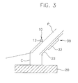
- FIG. 3 is a structural view showing a dead zone monitoring system according to a first embodiment of the present invention;
- FIG. 4A is a front view showing a guide in which a camera of the monitoring system as shown in FIG. 3 is installed;
- FIG. 4B is a front view showing a up-down regulating device on which a display device is installed; and
- FIG. 5 is structural view showing a dead zone monitoring system according to a second embodiment of the present invention.
-
- Hereinafter, the present invention will be described in detail with reference to the accompanying drawings.
- Referring to FIGS. 3, 4A, and 4B, a first embodiment of the dead zone monitoring system for monitoring the dead zone caused by a front pillar P of a vehicle includes a
photographing device 10, which is disposed outside the front pillar P for photographing driving conditions along front view or side-front view. - The photographing
device 10 includes acamera 12, and preferably the camera is a subminiature camera. Particularly, thecamera 12 is moveably installed to aguide 14 for adjusting a height and a position thereof. - The photographing
device 10 is connected with animage controller 20 by using acable 12. Theimage controller 20 can analyze, transform and process the information image that is photographed by the photographing device and actually shown on a display device successively described. - An image controller is connected with a
display device 30 by using animaginary signal cable 22. Though a great variety of thedisplay device 30 is known, amonitor 32 is more proper to thedisplay device 30. Particularly, a liquid crystal display device is more preferable to thedisplay device 30. Preferably, themonitor 32 includes an up-down regulator 34 for regulating a position thereof according to a driver's height or an altitude of a driver's seat. Therefore, the monitor can be installed to a position suitable for respective driver, so that the driver can monitor the dead zone caused by the front pillar with comfort and stability. - The photographing
device 10 can selectively includes adistance sensor 16. Thedistance sensor 16 can detect an obstacle in the dead zone and give warning signal and imagine information on the obstacle to the driver not to mention monitoring of the dead zone caused by the front pillar P. - FIG. 5 is structural view showing a dead zone monitoring system according to a second embodiment of the present invention.
- Referring to FIG. 5, the second embodiment of the dead zone monitoring system includes a
photographing device 40, which is disposed outside the front pillar P for photographing driving conditions along front view or side-front view. The photographingdevice 40 includes anoptical lens 42. Anoptical cable 50 is connected with thephotographing device 40. Theoptical cable 50 can transmit an image that is photographed through theoptical lens 42 and optically condensed. Theoptical cable 50 is preferably disposed under the vehicle for an outward appearance of the vehicle. - A
display device 60 is connected with theoptical cable 50. Thedisplay device 60 preferably includes anoptical monitor 62 which can optically display an image at a height of driver's eye through reverse order of photographing. - The dead zone monitoring system according to an embodiment of the present invention is operated as follows.
- At first, the
photographing device 10 is installed outside the front pillar P, and a cable C, theimage controller 20, and thedisplay device 30 are installed inside the front pillar P. Thedisplay device 30 is connected with thephotographing device 10 by using theimaginary signal cable 22. - The photographing
device 10 photographs image information through thecamera 12, and theimage controller 20 analyzes, transforms, and processes the image information. At last, the image information is displayed on themonitor 32 of thedisplay device 30 through theimaginary signal cable 22. Accordingly, the driver can observe the dead zone caused by the front pillar P of the vehicle by using themonitor 32 to thereby carefully and safely drive. At that time, the display device and the lens can be regulated to have a proper height suitable for respective drivers of diverse physical conditions. - When the
distance sensor 16 is selectively installed to the photographingdevice 10, thedistance sensor 16 can detect an obstacle in the dead zone and give warning signal and imagine information on the obstacle to the driver not to mention monitoring of the dead zone caused by the front pillar P. - Furthermore, when the photographing
device 40 disposed outside the front pillar P for photographing driving conditions along front view or side-front view includes theoptical lens 42, the photographingdevice 40 is operated as the same way as described in the above passage. As a result, the image information is displayed on theoptical monitor 62 of thedisplay device 60 through theoptical cable 50. - According to a preferred embodiment of the present invention, the dead zone monitoring system can completely monitor the dead zone caused by the front pillar of the vehicle and display an image information on the dead zone just in front of the driver's eyes, so that the driving view field is fully improved and security of driving is enhanced. Furthermore, the front pillar can be free from size restriction since the dead zone caused by the front pillar is removed by the monitoring system regardless of the front pillar size. Therefore, the front pillar can be formed to have a sufficient strength with escaping from the size restriction, so that security of the vehicle can be enhanced and the front pillar can be formed to give an aesthetic impression in the sense of sight.
- Although the present invention has been described in detail above, various changes, substitutions and alterations can be made thereto without departing from the true spirit and scope of the invention as defined by the appended claims.
Claims (4)
- A dead zone monitoring system for monitoring the dead zone of a vehicle comprising:a photographing device disposed on the front pillar for photographing a dead zone of a driver caused by the front pillar of the vehicle;an image controller connected with the photographing device for analyzing, transforming and processing an information image that is photographed by the photographing device; anda display device connected with the image controller by using a imaginary signal cable for displaying the information image provided from the image controller.
- The dead zone monitoring system as claimed in claim 1, wherein the display device includes a monitor, and a regulator for regulating a position of the monitor according to a driver's height or an altitude of a driver's seat.
- The dead zone monitoring system as claimed in claim 1, wherein the photographing device includes an optical lens, the imaginary signal cable is an optical cable, and the display device is an optical monitor.
- The dead zone monitoring system as in one of claims 1 to 3, wherein the photographing device includes a distance sensor, the distance sensor detecting an obstacle in the dead zone and warning the driver of existence of the obstacle.
Applications Claiming Priority (2)
| Application Number | Priority Date | Filing Date | Title |
|---|---|---|---|
| KR1020020037858A KR20040003216A (en) | 2002-07-02 | 2002-07-02 | A system for monitoring driving-dead space related to a front piller of vehicle |
| KR2002037858 | 2002-07-02 |
Publications (2)
| Publication Number | Publication Date |
|---|---|
| EP1378395A1 true EP1378395A1 (en) | 2004-01-07 |
| EP1378395B1 EP1378395B1 (en) | 2006-05-17 |
Family
ID=36571444
Family Applications (1)
| Application Number | Title | Priority Date | Filing Date |
|---|---|---|---|
| EP02021045A Expired - Lifetime EP1378395B1 (en) | 2002-07-02 | 2002-09-20 | A monitoring system for monitoring a dead zone related to a front pillar of a vehicle |
Country Status (5)
| Country | Link |
|---|---|
| US (1) | US20040004541A1 (en) |
| EP (1) | EP1378395B1 (en) |
| JP (1) | JP2004034957A (en) |
| KR (1) | KR20040003216A (en) |
| DE (1) | DE60211501T2 (en) |
Cited By (12)
| Publication number | Priority date | Publication date | Assignee | Title |
|---|---|---|---|---|
| GB2408874A (en) * | 2003-12-03 | 2005-06-08 | Ford Global Tech Llc | Reduction of blind-spots using in-vehicle displays |
| WO2006027563A1 (en) * | 2004-09-06 | 2006-03-16 | Mch Technology Limited | View enhancing system for a vehicle |
| DE102005006648A1 (en) * | 2005-02-14 | 2006-08-24 | Yang, Wen-Cheng, Yilan City | Visual watching device for car, has display, connected to camera, to show image taken by lens of camera to driver |
| EP1878618A3 (en) * | 2006-07-12 | 2008-12-31 | Aisin AW Co., Ltd. | Driving support method and apparatus |
| CN100490530C (en) * | 2005-10-07 | 2009-05-20 | 日产自动车株式会社 | Blind spot image display apparatus and method thereof for vehicle |
| DE102008059269A1 (en) | 2008-11-27 | 2010-06-02 | Josef Kirchler | Method for improving circumferential visibility in passenger car, involves producing image of angle area of environment, indicating produced image on image indicator system, and extracting and bringing section of camera image |
| CN101207802B (en) * | 2006-12-20 | 2011-11-02 | 爱信艾达株式会社 | Driving support method and driving support apparatus |
| CN107406042A (en) * | 2015-03-25 | 2017-11-28 | 河西工业株式会社 | Vehicle interior parts |
| CN111391755A (en) * | 2020-03-10 | 2020-07-10 | 京东方科技集团股份有限公司 | Display method, device and system of blind area image |
| US10967791B2 (en) | 2014-12-12 | 2021-04-06 | Serge B. HOYDA | System and process for viewing in blind spots |
| US11124116B2 (en) | 2014-12-12 | 2021-09-21 | Serge B. HOYDA | System and process for viewing in blind spots |
| US11518309B2 (en) | 2014-12-12 | 2022-12-06 | Serge Hoyda LLC | System and process for viewing in blind spots |
Families Citing this family (90)
| Publication number | Priority date | Publication date | Assignee | Title |
|---|---|---|---|---|
| US5910854A (en) | 1993-02-26 | 1999-06-08 | Donnelly Corporation | Electrochromic polymeric solid films, manufacturing electrochromic devices using such solid films, and processes for making such solid films and devices |
| US5668663A (en) | 1994-05-05 | 1997-09-16 | Donnelly Corporation | Electrochromic mirrors and devices |
| US6891563B2 (en) * | 1996-05-22 | 2005-05-10 | Donnelly Corporation | Vehicular vision system |
| US6172613B1 (en) * | 1998-02-18 | 2001-01-09 | Donnelly Corporation | Rearview mirror assembly incorporating vehicle information display |
| US6326613B1 (en) | 1998-01-07 | 2001-12-04 | Donnelly Corporation | Vehicle interior mirror assembly adapted for containing a rain sensor |
| US6124886A (en) | 1997-08-25 | 2000-09-26 | Donnelly Corporation | Modular rearview mirror assembly |
| US8294975B2 (en) | 1997-08-25 | 2012-10-23 | Donnelly Corporation | Automotive rearview mirror assembly |
| US6445287B1 (en) | 2000-02-28 | 2002-09-03 | Donnelly Corporation | Tire inflation assistance monitoring system |
| US8288711B2 (en) | 1998-01-07 | 2012-10-16 | Donnelly Corporation | Interior rearview mirror system with forwardly-viewing camera and a control |
| US6690268B2 (en) * | 2000-03-02 | 2004-02-10 | Donnelly Corporation | Video mirror systems incorporating an accessory module |
| US6693517B2 (en) | 2000-04-21 | 2004-02-17 | Donnelly Corporation | Vehicle mirror assembly communicating wirelessly with vehicle accessories and occupants |
| US6477464B2 (en) | 2000-03-09 | 2002-11-05 | Donnelly Corporation | Complete mirror-based global-positioning system (GPS) navigation solution |
| US6329925B1 (en) * | 1999-11-24 | 2001-12-11 | Donnelly Corporation | Rearview mirror assembly with added feature modular display |
| US7370983B2 (en) | 2000-03-02 | 2008-05-13 | Donnelly Corporation | Interior mirror assembly with display |
| US7167796B2 (en) | 2000-03-09 | 2007-01-23 | Donnelly Corporation | Vehicle navigation system for use with a telematics system |
| US7255451B2 (en) | 2002-09-20 | 2007-08-14 | Donnelly Corporation | Electro-optic mirror cell |
| EP1363810B1 (en) | 2001-01-23 | 2007-05-30 | Donnelly Corporation | Improved vehicular lighting system |
| US7581859B2 (en) | 2005-09-14 | 2009-09-01 | Donnelly Corp. | Display device for exterior rearview mirror |
| US6918674B2 (en) | 2002-05-03 | 2005-07-19 | Donnelly Corporation | Vehicle rearview mirror system |
| US7329013B2 (en) * | 2002-06-06 | 2008-02-12 | Donnelly Corporation | Interior rearview mirror system with compass |
| WO2003105099A1 (en) | 2002-06-06 | 2003-12-18 | Donnelly Corporation | Interior rearview mirror system with compass |
| AU2003278863A1 (en) | 2002-09-20 | 2004-04-08 | Donnelly Corporation | Mirror reflective element assembly |
| US7310177B2 (en) | 2002-09-20 | 2007-12-18 | Donnelly Corporation | Electro-optic reflective element assembly |
| US7289037B2 (en) | 2003-05-19 | 2007-10-30 | Donnelly Corporation | Mirror assembly for vehicle |
| US7446924B2 (en) * | 2003-10-02 | 2008-11-04 | Donnelly Corporation | Mirror reflective element assembly including electronic component |
| US7308341B2 (en) | 2003-10-14 | 2007-12-11 | Donnelly Corporation | Vehicle communication system |
| JP4973829B2 (en) | 2004-07-23 | 2012-07-11 | 上村工業株式会社 | Electro copper plating bath and electro copper plating method |
| TW200619067A (en) * | 2004-12-06 | 2006-06-16 | Arbl Co Ltd | Device for transparency equivalent A-pillar equivalent transparency of vehicle |
| JP2006213267A (en) * | 2005-02-07 | 2006-08-17 | Wen-Cheng Yang | Monitoring device for monitoring dead angle of front pillar of automobile |
| US20060176368A1 (en) * | 2005-02-07 | 2006-08-10 | Wen-Cheng Yang | Visual watching device for an automobile for detecting the dead angle caused by a front post |
| ATE517368T1 (en) | 2005-05-16 | 2011-08-15 | Donnelly Corp | VEHICLE MIRROR ARRANGEMENT WITH CHARACTER ON THE REFLECTIVE PART |
| JP2007124609A (en) | 2005-09-28 | 2007-05-17 | Nissan Motor Co Ltd | Vehicle surrounding image providing device |
| US8179435B2 (en) | 2005-09-28 | 2012-05-15 | Nissan Motor Co., Ltd. | Vehicle surroundings image providing system and method |
| EP1949666B1 (en) * | 2005-11-01 | 2013-07-17 | Magna Mirrors of America, Inc. | Interior rearview mirror with display |
| EP1991905B1 (en) | 2006-03-09 | 2011-05-11 | Gentex Corporation | Vehicle rearview assembly including a high intensity display |
| JP4936060B2 (en) * | 2007-07-10 | 2012-05-23 | 株式会社デンソー | Vehicle travel support device |
| KR100877887B1 (en) | 2007-10-10 | 2009-01-12 | 한국과학기술원 | Vision module for securing field of view of vehicle, windshield and method of securing field of view using the same |
| DE102008012646A1 (en) * | 2008-03-05 | 2009-09-10 | Carl Zeiss Microimaging Gmbh | Scene observing arrangement for use in agricultural commercial vehicle e.g. tractor, classifies covered partial area, information related to scene and/or information related to influence of scene for observer of screen |
| US8154418B2 (en) | 2008-03-31 | 2012-04-10 | Magna Mirrors Of America, Inc. | Interior rearview mirror system |
| JP5045812B2 (en) | 2008-06-24 | 2012-10-10 | トヨタ自動車株式会社 | Blind spot display device and driving support device |
| US9487144B2 (en) * | 2008-10-16 | 2016-11-08 | Magna Mirrors Of America, Inc. | Interior mirror assembly with display |
| KR101040291B1 (en) * | 2009-03-12 | 2011-06-10 | 알트론 주식회사 | Lightning prevention method and device in mobile communication system |
| KR200452660Y1 (en) * | 2009-05-27 | 2011-03-14 | 민경훈 | Blind Spot Mirror |
| KR101223406B1 (en) * | 2010-07-15 | 2013-01-16 | 고려대학교 산학협력단 | Display unit mounted on an interior of a vehicle to display outside view and method for controlling the unit |
| DE102011010624B4 (en) * | 2011-02-08 | 2014-10-16 | Mekra Lang Gmbh & Co. Kg | Display device for fields of view of a commercial vehicle |
| DE102011011048B9 (en) | 2011-02-11 | 2021-10-07 | Mekra Lang Gmbh & Co. Kg | Monitoring of the close range around a commercial vehicle |
| JP2012051563A (en) * | 2011-08-29 | 2012-03-15 | Fujio Miyazaki | Safety confirmation device |
| US8879139B2 (en) | 2012-04-24 | 2014-11-04 | Gentex Corporation | Display mirror assembly |
| DE102012015398B3 (en) | 2012-08-03 | 2013-10-24 | Mekra Lang Gmbh & Co. Kg | Mirror replacement system for a vehicle |
| DE102013002111B4 (en) | 2013-02-08 | 2021-11-18 | Mekra Lang Gmbh & Co. Kg | Vision system for vehicles, in particular commercial vehicles |
| US9598018B2 (en) | 2013-03-15 | 2017-03-21 | Gentex Corporation | Display mirror assembly |
| TW201438940A (en) * | 2013-04-11 | 2014-10-16 | Compal Electronics Inc | Image display method and image display system |
| AU2014326772B2 (en) | 2013-09-24 | 2017-07-20 | Gentex Corporation | Display mirror assembly |
| KR101491946B1 (en) * | 2014-01-10 | 2015-02-09 | 유성호 | Car pillar and car comprising the same |
| US9511715B2 (en) | 2014-01-31 | 2016-12-06 | Gentex Corporation | Backlighting assembly for display for reducing cross-hatching |
| US10705332B2 (en) | 2014-03-21 | 2020-07-07 | Gentex Corporation | Tri-modal display mirror assembly |
| US9834146B2 (en) | 2014-04-01 | 2017-12-05 | Gentex Corporation | Automatic display mirror assembly |
| US9694751B2 (en) | 2014-09-19 | 2017-07-04 | Gentex Corporation | Rearview assembly |
| WO2016073848A1 (en) | 2014-11-07 | 2016-05-12 | Gentex Corporation | Full display mirror actuator |
| KR101977685B1 (en) | 2014-11-13 | 2019-05-13 | 젠텍스 코포레이션 | Rearview mirror system with a display |
| KR101997815B1 (en) | 2014-12-03 | 2019-07-08 | 젠텍스 코포레이션 | Display mirror assembly |
| USD746744S1 (en) | 2014-12-05 | 2016-01-05 | Gentex Corporation | Rearview device |
| US9744907B2 (en) | 2014-12-29 | 2017-08-29 | Gentex Corporation | Vehicle vision system having adjustable displayed field of view |
| US9720278B2 (en) | 2015-01-22 | 2017-08-01 | Gentex Corporation | Low cost optical film stack |
| KR200477941Y1 (en) * | 2015-02-09 | 2015-08-13 | 조익준 | View guarantee system for vehicle |
| JP6202028B2 (en) * | 2015-03-24 | 2017-09-27 | トヨタ自動車株式会社 | Arrangement structure of surrounding information detection sensor and autonomous driving vehicle |
| US10144424B2 (en) * | 2015-04-09 | 2018-12-04 | Toyota Jidosha Kabushiki Kaisha | Arrangement structure for vicinity information detection sensor |
| JP2018513810A (en) | 2015-04-20 | 2018-05-31 | ジェンテックス コーポレイション | Rear view assembly with decoration |
| WO2016187215A1 (en) | 2015-05-18 | 2016-11-24 | Gentex Corporation | Full display rearview device |
| KR102135427B1 (en) | 2015-06-22 | 2020-07-17 | 젠텍스 코포레이션 | Systems and methods for processing streamed video images to correct flicker of amplitude-modulated light |
| USD798207S1 (en) | 2015-10-30 | 2017-09-26 | Gentex Corporation | Rearview mirror assembly |
| WO2017075420A1 (en) | 2015-10-30 | 2017-05-04 | Gentex Corporation | Toggle paddle |
| US9994156B2 (en) | 2015-10-30 | 2018-06-12 | Gentex Corporation | Rearview device |
| USD797627S1 (en) | 2015-10-30 | 2017-09-19 | Gentex Corporation | Rearview mirror device |
| USD800618S1 (en) | 2015-11-02 | 2017-10-24 | Gentex Corporation | Toggle paddle for a rear view device |
| USD845851S1 (en) | 2016-03-31 | 2019-04-16 | Gentex Corporation | Rearview device |
| USD817238S1 (en) | 2016-04-29 | 2018-05-08 | Gentex Corporation | Rearview device |
| US10025138B2 (en) | 2016-06-06 | 2018-07-17 | Gentex Corporation | Illuminating display with light gathering structure |
| CN107776488A (en) * | 2016-08-24 | 2018-03-09 | 京东方科技集团股份有限公司 | Automobile using auxiliary display system, display methods and automobile |
| DE102016221434B4 (en) | 2016-11-01 | 2020-01-16 | Continental Automotive Gmbh | Monitor of a camera monitor system |
| US9959767B1 (en) * | 2016-11-03 | 2018-05-01 | GM Global Technology Operations LLC | Method and apparatus for warning of objects |
| USD809984S1 (en) | 2016-12-07 | 2018-02-13 | Gentex Corporation | Rearview assembly |
| USD854473S1 (en) | 2016-12-16 | 2019-07-23 | Gentex Corporation | Rearview assembly |
| US20180191966A1 (en) | 2016-12-30 | 2018-07-05 | Gentex Corporation | Full display mirror with on-demand spotter view |
| US10735638B2 (en) | 2017-03-17 | 2020-08-04 | Gentex Corporation | Dual display reverse camera system |
| KR102347689B1 (en) | 2017-04-10 | 2022-01-05 | 현대자동차주식회사 | Apparatus for Displaying the Blind Spot of the Vehicle |
| ES2695757A1 (en) * | 2017-07-06 | 2019-01-10 | Maruri Emilio Placer | Visualization device and procedure to eliminate dead fields of vision in vehicles (Machine-translation by Google Translate, not legally binding) |
| US11391820B2 (en) | 2019-04-26 | 2022-07-19 | Waymo L LC | Mirrors to extend sensor field of view in self-driving vehicles |
| US20220363194A1 (en) * | 2021-05-11 | 2022-11-17 | Magna Electronics Inc. | Vehicular display system with a-pillar display |
| EP4388243A4 (en) | 2021-08-20 | 2024-12-04 | Gentex Corporation | Lighting assembly and illumination system having a lighting assembly |
Citations (4)
| Publication number | Priority date | Publication date | Assignee | Title |
|---|---|---|---|---|
| DE3900667A1 (en) * | 1989-01-09 | 1990-07-12 | Fahri Kirsever | Periscope for a motor vehicle |
| EP1024057A2 (en) * | 1999-01-26 | 2000-08-02 | Mazda Motor Corporation | Display apparatus on a vehicle |
| DE10037129A1 (en) * | 1999-09-13 | 2001-04-26 | Volkswagen Ag | Parking or maneuvering assistance device for motor vehicle uses several cameras arranged on outside of vehicle |
| EP1285814A1 (en) * | 2001-08-21 | 2003-02-26 | Ford Global Technologies, Inc., A subsidiary of Ford Motor Company | Monitoring device for vehicles |
Family Cites Families (8)
| Publication number | Priority date | Publication date | Assignee | Title |
|---|---|---|---|---|
| US4933691A (en) * | 1989-01-09 | 1990-06-12 | Leslie Dennis R | Surveillance camera support |
| JPH06166380A (en) * | 1992-12-01 | 1994-06-14 | Saburo Osawa | Front pillar structure of automobile |
| US6498620B2 (en) * | 1993-02-26 | 2002-12-24 | Donnelly Corporation | Vision system for a vehicle including an image capture device and a display system having a long focal length |
| US5670935A (en) * | 1993-02-26 | 1997-09-23 | Donnelly Corporation | Rearview vision system for vehicle including panoramic view |
| US5883739A (en) * | 1993-10-04 | 1999-03-16 | Honda Giken Kogyo Kabushiki Kaisha | Information display device for vehicle |
| JP3431678B2 (en) * | 1994-02-14 | 2003-07-28 | 三菱自動車工業株式会社 | Ambient situation display device for vehicles |
| JPH11115546A (en) * | 1997-10-17 | 1999-04-27 | Harness Syst Tech Res Ltd | Display device for vehicles |
| JP2001026283A (en) * | 1999-07-12 | 2001-01-30 | Hiroyuki Nishimuta | Transparent front pillar of automobile |
-
2002
- 2002-07-02 KR KR1020020037858A patent/KR20040003216A/en not_active Ceased
- 2002-08-27 JP JP2002247180A patent/JP2004034957A/en active Pending
- 2002-09-20 DE DE60211501T patent/DE60211501T2/en not_active Expired - Fee Related
- 2002-09-20 EP EP02021045A patent/EP1378395B1/en not_active Expired - Lifetime
-
2003
- 2003-02-28 US US10/378,055 patent/US20040004541A1/en not_active Abandoned
Patent Citations (4)
| Publication number | Priority date | Publication date | Assignee | Title |
|---|---|---|---|---|
| DE3900667A1 (en) * | 1989-01-09 | 1990-07-12 | Fahri Kirsever | Periscope for a motor vehicle |
| EP1024057A2 (en) * | 1999-01-26 | 2000-08-02 | Mazda Motor Corporation | Display apparatus on a vehicle |
| DE10037129A1 (en) * | 1999-09-13 | 2001-04-26 | Volkswagen Ag | Parking or maneuvering assistance device for motor vehicle uses several cameras arranged on outside of vehicle |
| EP1285814A1 (en) * | 2001-08-21 | 2003-02-26 | Ford Global Technologies, Inc., A subsidiary of Ford Motor Company | Monitoring device for vehicles |
Cited By (16)
| Publication number | Priority date | Publication date | Assignee | Title |
|---|---|---|---|---|
| GB2408874A (en) * | 2003-12-03 | 2005-06-08 | Ford Global Tech Llc | Reduction of blind-spots using in-vehicle displays |
| WO2006027563A1 (en) * | 2004-09-06 | 2006-03-16 | Mch Technology Limited | View enhancing system for a vehicle |
| DE102005006648A1 (en) * | 2005-02-14 | 2006-08-24 | Yang, Wen-Cheng, Yilan City | Visual watching device for car, has display, connected to camera, to show image taken by lens of camera to driver |
| CN100490530C (en) * | 2005-10-07 | 2009-05-20 | 日产自动车株式会社 | Blind spot image display apparatus and method thereof for vehicle |
| EP1878618A3 (en) * | 2006-07-12 | 2008-12-31 | Aisin AW Co., Ltd. | Driving support method and apparatus |
| CN101106703B (en) * | 2006-07-12 | 2011-06-22 | 爱信艾达株式会社 | Driving support method and apparatus |
| CN101207802B (en) * | 2006-12-20 | 2011-11-02 | 爱信艾达株式会社 | Driving support method and driving support apparatus |
| DE102008059269A1 (en) | 2008-11-27 | 2010-06-02 | Josef Kirchler | Method for improving circumferential visibility in passenger car, involves producing image of angle area of environment, indicating produced image on image indicator system, and extracting and bringing section of camera image |
| US10967791B2 (en) | 2014-12-12 | 2021-04-06 | Serge B. HOYDA | System and process for viewing in blind spots |
| US11124116B2 (en) | 2014-12-12 | 2021-09-21 | Serge B. HOYDA | System and process for viewing in blind spots |
| US11518309B2 (en) | 2014-12-12 | 2022-12-06 | Serge Hoyda LLC | System and process for viewing in blind spots |
| US10279735B2 (en) | 2015-03-25 | 2019-05-07 | Kasai Kogyo Co., Ltd. | Vehicle interior component |
| CN107406042B (en) * | 2015-03-25 | 2019-10-25 | 河西工业株式会社 | Vehicle interior parts |
| CN107406042A (en) * | 2015-03-25 | 2017-11-28 | 河西工业株式会社 | Vehicle interior parts |
| CN111391755A (en) * | 2020-03-10 | 2020-07-10 | 京东方科技集团股份有限公司 | Display method, device and system of blind area image |
| CN111391755B (en) * | 2020-03-10 | 2021-10-12 | 京东方科技集团股份有限公司 | Display method, device and system of blind area image |
Also Published As
| Publication number | Publication date |
|---|---|
| DE60211501D1 (en) | 2006-06-22 |
| DE60211501T2 (en) | 2007-05-03 |
| US20040004541A1 (en) | 2004-01-08 |
| KR20040003216A (en) | 2004-01-13 |
| JP2004034957A (en) | 2004-02-05 |
| EP1378395B1 (en) | 2006-05-17 |
Similar Documents
| Publication | Publication Date | Title |
|---|---|---|
| EP1378395B1 (en) | A monitoring system for monitoring a dead zone related to a front pillar of a vehicle | |
| CN108621923B (en) | Display system for vehicle and control method for display system for vehicle | |
| JP3800172B2 (en) | Vehicle periphery monitoring device | |
| JP3431678B2 (en) | Ambient situation display device for vehicles | |
| US20160200254A1 (en) | Method and System for Preventing Blind Spots | |
| CN109641523A (en) | Method for controlling a display device of a motor vehicle and a motor vehicle with a display device | |
| CN113448096B (en) | Display device for vehicle | |
| CN112849158A (en) | Image display method, vehicle-mounted display system and automobile | |
| JP2018182646A (en) | Image display device | |
| US10836311B2 (en) | Information-presenting device | |
| CN112009368A (en) | 360-degree panoramic image ultrasonic radar control system and method for fuel cell hydrogen energy automobile | |
| KR101866042B1 (en) | Backward driving assistant system | |
| JP2005204132A (en) | Driving assistance device | |
| CN106291928A (en) | The method of the projection arrangement of the projection arrangement of motor vehicles and operation motor vehicles | |
| JP2006137209A (en) | Anti-glare device for vehicle | |
| KR20190062055A (en) | Side front blind area display apparatus for vehicle and the method thereof | |
| CN112532915A (en) | Vehicle exterior monitoring device | |
| JP2007290570A (en) | Vehicle display device | |
| KR102311954B1 (en) | Automotive blind spot video output device | |
| JP2019038372A (en) | Image display device | |
| KR200152945Y1 (en) | Side-mirror using camera and door safety device. | |
| US20210122293A1 (en) | Peripheral information acquisition device and vehicle | |
| CN214874511U (en) | Automobile visual system | |
| US20260061935A1 (en) | Rear seat viewing device for a vehicle and method therefor | |
| US20250346183A1 (en) | Camera monitor system with picture-in-picture feature |
Legal Events
| Date | Code | Title | Description |
|---|---|---|---|
| PUAI | Public reference made under article 153(3) epc to a published international application that has entered the european phase |
Free format text: ORIGINAL CODE: 0009012 |
|
| 17P | Request for examination filed |
Effective date: 20021016 |
|
| AK | Designated contracting states |
Kind code of ref document: A1 Designated state(s): AT BE BG CH CY CZ DE DK EE ES FI FR GB GR IE IT LI LU MC NL PT SE SK TR |
|
| AX | Request for extension of the european patent |
Extension state: AL LT LV MK RO SI |
|
| AKX | Designation fees paid |
Designated state(s): DE FR GB |
|
| 17Q | First examination report despatched |
Effective date: 20050413 |
|
| GRAP | Despatch of communication of intention to grant a patent |
Free format text: ORIGINAL CODE: EPIDOSNIGR1 |
|
| GRAS | Grant fee paid |
Free format text: ORIGINAL CODE: EPIDOSNIGR3 |
|
| GRAA | (expected) grant |
Free format text: ORIGINAL CODE: 0009210 |
|
| AK | Designated contracting states |
Kind code of ref document: B1 Designated state(s): DE FR GB |
|
| REG | Reference to a national code |
Ref country code: GB Ref legal event code: FG4D |
|
| REF | Corresponds to: |
Ref document number: 60211501 Country of ref document: DE Date of ref document: 20060622 Kind code of ref document: P |
|
| PGFP | Annual fee paid to national office [announced via postgrant information from national office to epo] |
Ref country code: FR Payment date: 20060922 Year of fee payment: 5 Ref country code: GB Payment date: 20060922 Year of fee payment: 5 |
|
| PGFP | Annual fee paid to national office [announced via postgrant information from national office to epo] |
Ref country code: DE Payment date: 20061002 Year of fee payment: 5 |
|
| ET | Fr: translation filed | ||
| PLBE | No opposition filed within time limit |
Free format text: ORIGINAL CODE: 0009261 |
|
| STAA | Information on the status of an ep patent application or granted ep patent |
Free format text: STATUS: NO OPPOSITION FILED WITHIN TIME LIMIT |
|
| 26N | No opposition filed |
Effective date: 20070220 |
|
| GBPC | Gb: european patent ceased through non-payment of renewal fee |
Effective date: 20070920 |
|
| PG25 | Lapsed in a contracting state [announced via postgrant information from national office to epo] |
Ref country code: DE Free format text: LAPSE BECAUSE OF NON-PAYMENT OF DUE FEES Effective date: 20080401 |
|
| REG | Reference to a national code |
Ref country code: FR Ref legal event code: ST Effective date: 20080531 |
|
| PG25 | Lapsed in a contracting state [announced via postgrant information from national office to epo] |
Ref country code: FR Free format text: LAPSE BECAUSE OF NON-PAYMENT OF DUE FEES Effective date: 20071001 |
|
| PG25 | Lapsed in a contracting state [announced via postgrant information from national office to epo] |
Ref country code: GB Free format text: LAPSE BECAUSE OF NON-PAYMENT OF DUE FEES Effective date: 20070920 |