EP1376417A1 - Method and system for emulating a circuit under test associated with a test environment - Google Patents
Method and system for emulating a circuit under test associated with a test environment Download PDFInfo
- Publication number
- EP1376417A1 EP1376417A1 EP03291452A EP03291452A EP1376417A1 EP 1376417 A1 EP1376417 A1 EP 1376417A1 EP 03291452 A EP03291452 A EP 03291452A EP 03291452 A EP03291452 A EP 03291452A EP 1376417 A1 EP1376417 A1 EP 1376417A1
- Authority
- EP
- European Patent Office
- Prior art keywords
- reconfigurable
- circuit
- test
- hardware
- under test
- Prior art date
- Legal status (The legal status is an assumption and is not a legal conclusion. Google has not performed a legal analysis and makes no representation as to the accuracy of the status listed.)
- Granted
Links
Images


Classifications
-
- G—PHYSICS
- G01—MEASURING; TESTING
- G01R—MEASURING ELECTRIC VARIABLES; MEASURING MAGNETIC VARIABLES
- G01R31/00—Arrangements for testing electric properties; Arrangements for locating electric faults; Arrangements for electrical testing characterised by what is being tested not provided for elsewhere
- G01R31/28—Testing of electronic circuits, e.g. by signal tracer
- G01R31/317—Testing of digital circuits
- G01R31/3181—Functional testing
- G01R31/3183—Generation of test inputs, e.g. test vectors, patterns or sequences
- G01R31/318314—Tools, e.g. program interfaces, test suite, test bench, simulation hardware, test compiler, test program languages
-
- G—PHYSICS
- G01—MEASURING; TESTING
- G01R—MEASURING ELECTRIC VARIABLES; MEASURING MAGNETIC VARIABLES
- G01R31/00—Arrangements for testing electric properties; Arrangements for locating electric faults; Arrangements for electrical testing characterised by what is being tested not provided for elsewhere
- G01R31/28—Testing of electronic circuits, e.g. by signal tracer
- G01R31/317—Testing of digital circuits
- G01R31/3181—Functional testing
- G01R31/3183—Generation of test inputs, e.g. test vectors, patterns or sequences
- G01R31/318342—Generation of test inputs, e.g. test vectors, patterns or sequences by preliminary fault modelling, e.g. analysis, simulation
- G01R31/318357—Simulation
-
- G—PHYSICS
- G06—COMPUTING; CALCULATING OR COUNTING
- G06F—ELECTRIC DIGITAL DATA PROCESSING
- G06F11/00—Error detection; Error correction; Monitoring
- G06F11/22—Detection or location of defective computer hardware by testing during standby operation or during idle time, e.g. start-up testing
- G06F11/26—Functional testing
- G06F11/261—Functional testing by simulating additional hardware, e.g. fault simulation
-
- G—PHYSICS
- G06—COMPUTING; CALCULATING OR COUNTING
- G06F—ELECTRIC DIGITAL DATA PROCESSING
- G06F30/00—Computer-aided design [CAD]
- G06F30/30—Circuit design
- G06F30/32—Circuit design at the digital level
- G06F30/33—Design verification, e.g. functional simulation or model checking
- G06F30/3308—Design verification, e.g. functional simulation or model checking using simulation
- G06F30/331—Design verification, e.g. functional simulation or model checking using simulation with hardware acceleration, e.g. by using field programmable gate array [FPGA] or emulation
Definitions
- the invention relates to the field of electronic design computer assisted (CAD) and more particularly that of functional verification of integrated circuits and more usually electronic systems.
- CAD computer assisted
- the invention applies in particular to the implementation of a test environment of a circuit which one seeks to validate the functioning (and called “circuit under test") and which is emulated entirely or partly by a reconfigurable hardware system.
- reconfigurable hardware systems generally encompass both emulation systems (or “emulators”) and systems prototyping. Subsequently, the term “emulator” will be used to designate a “reconfigurable hardware system”, and therefore we will include under this term, prototyping systems.
- Reconfigurable hardware systems consist of one or more of several cards on which circuits are found Field Programmable Gate Array (FPGA) reconfigurable custom reconfigurable circuits, which are connected between them according to fixed or reconfigurable means.
- the cards constituting the reconfigurable hardware system can be plugged in one or more racks.
- An interface ensures the communication of the reconfigurable hardware system with a control computer (or host computer).
- the first hardware systems reconfigurable of this type were reduced to their simplest expression, that is to say a single reconfigurable circuit mounted on a card and which proposed a single mode of validation, namely emulation in-circuit.
- the circuit test environment consists of the target system to eventually receive the circuit under test, cables and connectors that allow the target system to communicate with the reconfigurable circuit placed on another circuit board.
- the circuits reconfigurable are generally slower than custom-made circuits one seeks to achieve and validate, it might be necessary to slow down the speed of the target system so that the reconfigurable circuit works correctly.
- test environment has characteristics different in terms of performance, ease of implementation and and flexibility of use. From the point of view of performance, a general rule is that the gain is maximum vis-à-vis of a software simulation when the test environment is made directly by material.
- This material can be the system target (in-circuit emulation mode) or an implementation of the test environment by the reconfigurable hardware system (test-vector based stimulation or hardware model of embedded stimulation). Nevertheless, this approach is not always possible, in particular because the description of a model hardware of a test environment can be very difficult to achieve and maintain. Circuit designers often prefer model their test environment at a level of abstraction to the times higher and different from the one used to describe their circuit under test.
- a current trend is to stimulate the circuit under test by software looking for a performance gain similar to that obtained by a reconfigurable system in a mode where it is stimulated only by material. This approach is particularly interesting when the target system has not yet finalized, when the test environment is likely to change importantly during the validation of the circuit under test or finally when looking to debug the circuit under test at a level of higher abstraction.
- This interface has been specifically defined for support a type of communication between a software model and the circuit under test called transactional.
- a transaction can be defined as a specific sequence of transition on a set signals during a given period.
- the part of the test environment that is embedded in the reconfigurable hardware system and the circuit under test are both implanted by the same resources configurable. This results in a very strong dependence between the test environment and the circuit under test. As a result, change in the test environment (for example a transactor) may lead to a recompilation of the circuit under test while it did not change. Conversely, a modification in the circuit under test may involve recompiling the test environment while this one has not changed.
- the material used is material generic that is not necessarily suitable for the implementation of a test environment, whether in terms of speed or density. Indeed, the structure of a test environment is very specific. Some of these blocks must operate at significant frequencies difficult to obtain and secure with a hardware system generic reconfigurable. The emulation of the material part of the test environment by a generic emulator can finally have a negative impact on the overall performance of the system emulation.
- reconfigurable circuits can indeed cover the needs of developers of intellectual property blocks, specific circuits (ASIC), and by definition of circuit-based circuits reconfigurable (FPGA).
- ASIC intellectual property blocks
- FPGA circuit-based circuits reconfigurable
- the invention aims to provide a solution to these problems.
- the aim of the invention is to define a new architecture of simulation / emulation platform taking into account the evolution of the complexity of test environments, performance requirements and the evolution of reconfigurable circuit technology.
- the invention aims to allow the description complex mixed hardware and software test environments while offering performance and integration in line with market demand.
- the simulation / emulation platform according to the invention is thus based on an approach where we separate the reconfigurable system emulating the circuit under test, from that emulating the hardware part of its test environment.
- This approach is particularly applicable well in case the reconfigurable hardware system emulating the circuit under test is based on a single reconfigurable circuit, but it can be easily extended to cases of more reconfigurable hardware systems complex.
- each material part can be for example realized by means of a reconfigurable circuit of the FPGA type.
- the first generation phase and the second phase of generation can be performed in parallel or sequentially and in the latter case the order does not matter. Indeed, we can perform the first generation phase before or after the second generation phase.
- the first generation phase involves the production of a logic circuit consisting of a network of logical gates representative of the test environment as well as compilation guidelines.
- the first generation phase also includes a compilation of this logical circuit in the light of those directives, so as to obtain the first configuration file.
- the test environment includes a set of pilots and monitors.
- the production of the said logic circuit then involves the formation of material blocks under the logical gate network form, these hardware blocks representing software driver / monitor interfaces, driver interfaces / monitors for hardware stimulation and emulated hardware stimulation drivers / monitors.
- the production of logic circuit also involves forming an interface block enabling the aforementioned hardware blocks to communicate with the emulator of the circuit under test.
- the production of the circuit logic uses as input parameter a description of the assignment of the logic inputs and outputs of the circuit under test to the pins of the emulator.
- the production of the logic circuit uses as input parameter a description of interface of the circuit under test and outputs a description of the assignment of the logic inputs / outputs of the circuit under test to the emulator pins, this output description being then a constraint parameter for the second generation phase.
- the subject of the invention is also an emulation system, intended to emulate a circuit under test associated with an environment of test.
- the system includes a reconfigurable hardware test bench capable of emulating at least part of the test environment, this test bench being connected between a host computer and a hardware emulator reconfigurable separate from the test bench and able to emulate at least part of the circuit under test.
- the system also comprises first means of generation able to generate a first configuration file of the test environment, and second generation means suitable to generate a second configuration file of at least a part circuit under test.
- the test bench reconfigurable comprises a so-called fixed part and at least one circuit reconfigurable able to realize the emulated part of the environment test.
- a fixed part is understood as being a part not varying according to the test environment by opposition to a reconfigurable part that is configured to the case by case depending on the test environment.
- the fixed part could be realized by fixed circuits (not reconfigurable), or possibly by reconfigurable circuits but with fixed circuitry.
- the fixed part comprises at least one control circuit and an interface circuit with the host computer.
- the reconfigurable circuit realizing the emulated part of the test environment is otherwise able to include at least software driver / monitor interfaces that are capable of to establish a communication with at least one software process run on a host computer, as well as drivers / monitors from material stimulation emulated.
- the fixed part may also include pilots / instructors additional actual equipment.
- the reconfigurable circuit realizing the emulated part of the test environment is then able to include in in addition to interfaces with these real hardware drivers / monitors additional.
- the fixed part may also comprise a circuit interface with a target device, so as to be able to perform a in-circuit emulation.
- the fixed part can also come in the form of a single circuit which then integrates the control circuit, the interface circuit with the host computer and the interface circuit with the target device.
- interface circuit with the target device can also be realized in the reconfigurable circuits or circuits realizing the emulated part of the test environment, which limits the number of circuits to cross to communicate the circuit under test with its target device.
- test bench and the emulator can be realized on a electronic card external to the host computer and connected to the card mother of it through an interface card.
- test bench can be realized on a first electronic card external to the host computer and connected to the card mother of it through an interface card while the emulator can be performed on one or more other external cards at the host computer connected to said first external card.
- test bench and the emulator can be realized on an internal electronic card incorporated into the host computer.
- the interface circuit with a possible device target can be realized on an electronic card external to the computer host and able to be connected to said internal electronic card.
- the invention also relates to an electronic card, intended to be connected to the motherboard of a host computer, featuring a reconfigurable hardware test bench capable of emulating at least part of a test environment associated with a circuit under test, and a reconfigurable hardware emulator distinct from the test, connected to the reconfigurable test bench and capable of emulating least part of the circuit under test.
- the reconfigurable test bench may comprise a so-called fixed and at least one reconfigurable circuit capable of realizing the part emulated from the test environment.
- a circuit under test can be modeled by a description behavioral at different levels of abstraction.
- the behaviour of the circuit can thus be described by a software model (for example a C or C ++ program) and / or a hardware model expressed at Behavioral Transfer, Register Transfer (RTL) or as a network of doors.
- a hardware model can be simulated by software specialized called hardware description simulator or else it can be emulated by a reconfigurable hardware system. In the second case, the emulated model corresponds directly to a material realization.
- the invention relates to circuits under test of which at least one part or all of the description is emulated by a system reconfigurable hardware.
- this one can be defined as representing all the means implemented by the designer of integrated circuits to validate his circuit.
- the the inputs / outputs of the circuit under test are stimulated and observed by the test environment. Stimulation can be produced in a way random or taking into account the structural features and functionalities of the circuit under test. Observation generally integrates an analysis of the response of the circuit under test with possibly a comparison with the expected answer. This expected answer is determined according to the basic specifications of the circuit to be tested.
- the test environment can be defined through a complex software / hardware package. It can be defined by a combination of software and / or hardware models. These models stimulate and observe the circuit under test and we will call later pilots / instructors.
- the material models of the test environment can also be simulated or emulated. This being, part of the test environment can also be performed by real material.
- a reconfigurable hardware system can correspond to a single reconfigurable circuit or any circuit arrangement Reconfigurable.
- a reconfigurable circuit may be of the FPGA type, such marketed by the XILINX or ALTERA companies, or Custom circuit having reconfigurability properties.
- the reference SEM designates a system emulation according to the invention.
- This system includes an emulator of the EML circuit under test and a set ENVT realized in test environment for this same circuit under test.
- a reconfigurable test bench BTR is the piece Central to the test environment. It allows the emulator of the circuit under test to communicate with an OH host computer (be it a personal computer, a workstation or a server) and with a possible target device (or system) to receive the circuit under test (in the case of an in-circuit emulation).
- the reconfigurable test bench BTR communicates with the host computer OH through a fast bus such as a bus PCI, AGP or a fast interface such as ethernet, SCSI.
- a fast bus such as a bus PCI, AGP or a fast interface such as ethernet, SCSI.
- the reconfigurable test bench BTR and the emulator EML are arranged on an internal card CINT embedded in the host computer and connected to the CMR motherboard of this host computer.
- an internal card can be a PCI card standard format, or an AGP card.
- the reconfigurable test bench BTR comprises a central portion CR comprising, as will be seen in more detail below, at least one control circuit and at least one reconfigurable circuit, a clock generator GH, and static and / or dynamic memory circuits CMM.
- the clock generator produces a basic system clock useful for the operation of the reconfigurable test bench and possibly the emulator when the clocks do not come of the target system.
- the source of the generator can be a quartz or the clock coming from the bus interface of the host computer.
- Static and / or dynamic memories can store some useful information during an emulation.
- IFSC IFSC external interface circuit
- an external card CXT connected to the internal card CINT, this interface circuit providing the interface between the central portion CR of the reconfigurable test bench and SYC target system.
- the central part CR of the reconfigurable test bench comprises here, as illustrated in FIG. 4, a control circuit CCTL, a reconfigurable interface circuit with the CRFG emulator and a circuit CIBS bus interface.
- the CIBS bus interface circuit ensures the communication of the internal CINT card with the host computer bus. This interface can be achieved using a specialized circuit of commerce such than those marketed by PLX.
- the circuit connection reconfigurable interface with the CRFG emulator at the circuit CIBS bus interface provides minimal latency in the communication between the host computer processor and the circuit under test.
- the control circuit performs the fixed functions of the test bench reconfigurable. Its content is therefore defined independently of circuit under test and the test environment used. It can include nevertheless some programmable parts.
- the reconfigurable interface circuit with the CRFG emulator serves to realize the interface of the reconfigurable test bench with the emulator of the circuit under test EML.
- This circuit CRFG also realizes the hardware parts of the test environment that will be defined by the user. The content of this circuit depends on the environment used test and its interface with the circuit under test.
- CMM memory circuits include circuit circuits CMMS static memory, for example of the SRAM or SSRAM type, as well as the dynamic memory circuits, for example of type SDRAM.
- Dynamic memories can be implanted with separate memory components or using memory modules. The memory components have the advantage of facilitating the phase of placement routing on the map while the bars add more than flexibility in the further evolution of the product.
- the hardware architecture of the reconfigurable test bench has the advantage of proposing a decoupling between the actual core of the reconfigurable test bench realizing critical functions at the speed of operation and its interface with the emulator of the circuit under test requiring more reconfigurability. This gives better control critical parts at the operating speed level and allows to avoid compiling the control circuit when the environment of test changes.
- the solution that consists in using only one circuit reconfigurable to realize both the control circuit and interface with the emulator of the circuit under test presents the advantages of simplified design and lower cost.
- control circuit realizes the basic functions of the reconfigurable test bench. These functions are independent of the test environment of the circuit to be emulated.
- the control circuit is initialized at the start of the card and this independently of the circuits under test which will be emulated later.
- the reconfigurable test bench includes an internal bus called communication bus, spreading both on the control circuit and the reconfigurable interface circuit (s) CRFG.
- the communication bus is not completely controlled by the host computer, even if it is directly or indirectly the origin of many transactions. So, at any time, any block equipment connected to the bus may seek to communicate with another block without the initiator of this transaction being necessarily the host computer.
- Access to the communication bus is managed by a block ABG global arbitration scheme in the control circuit (FIG. 5) and by a local arbitration block in each interface circuit of the emulator.
- a block of the control circuit can therefore communicate with a block of the reconfigurable interface circuit in a transparent manner, that is to say as if it were part of the control circuit.
- Many arbitration mechanisms can be used to determine which block material will take hold at some point. For example, a arbitration mechanism may be to rotate priorities each cycle of the communication bus so that an access request the bus always ends up being served.
- the control circuit also includes the control part of a hardware logical analyzer AL.
- This block consists of one or several programmable logic controllers whose state evolves according to the predefined or programmable triggers produced by the circuit reconfigurable interface of the CRFG emulator, as well as a set counters and internal flags.
- This hardware block allows control a simulation sequence and make the most of the trace memories that we make based on the memories static or dynamic connected to the control circuit.
- the analyzer logic thus formed takes up the general characteristics of a conventional logic analyzer except that it has the properties reconfigurations of the reconfigurable interface circuit to achieve a hardware trace monitor and triggers.
- a clock controller CHL is synchronized by a clock basic system (or primary clock) that can also serve advantageously, to clock the communication bus of the test bench reconfigurable.
- the clock controller produces groups of secondary clock signals, corresponding to the clocks of the circuit under test and to the clocks of the various pilots / instructors and pilot / monitor interfaces found in the circuit (s) reconfigurable interface with the emulator.
- the clock controller CHL can also receive clocks from the system as input target when the circuit under test is fully synchronized or for partly by external clocks.
- the clock controller includes several generators independent signals providing secondary clocks.
- the secondary clocks produced by a generator are interrelated according to determined frequency and phase ratios.
- Each generator can communicate with different hardware blocks of the bench reconfigurable test to determine the progress of the clocks which it must provide to the circuit under test and to drivers / monitors. So a software driver can for example slow down a clock produced by a generator so that it adapts to its pacing rate, or a hardware trace driver can inhibit some secondary clocks from some generators for a certain period of time to perform a data transfer from the trace memory to the host computer.
- a BC block of combination of control signals centralizes control signals coming from or going to the different hardware blocks involved in the control of the clocks.
- SDRAM dynamic memory CSD controller enables to read or write the dynamic memories connected to the circuit of CCTL control from host computer or circuit reconfigurable interface CRFG.
- a controller CSR SRAM static memory allows you to read or write static memories connected to the control circuit CCTL from the host computer or CRFG reconfigurable interface circuit.
- these memories are used to sample the data from the interface bus with the CRFG reconfigurable interface emulator.
- These memories can also be used for other purposes such as memorizing different configurations of the circuit under test emulator, keep test vectors or software applications executed by a hardware model of a complete system.
- the control circuit CCTL also includes an interface JTAG compliant IFG test kit for fast access to the map resources from the host computer and this, without go through an external cable. Such an interface can be used from a classic way to perform production tests by checking in particular the quality of the connections between the different components of the map. This interface also serves, when starting the card, for identify the reconfigurable circuits used on the platform.
- the CCTL control block also features an interface IFCF configuration and replay, which allows you to configure or reread the configuration of the various reconfigurable circuits of the emulation system.
- a CIS in-situ controller allows the implementation of in-circuit emulation by booting the IFSC external interface circuit and controlling the communication between the emulated circuit under test and the target system.
- control circuit CCTL includes interfaces I / F to different components external to the control circuit.
- this one is modeled as a set of PLi and MNi drivers / monitors interacting with the circuit under test DUT.
- PLi drivers are used to boost the circuit under test while MNi monitors are used to observe, that is, to analyze the response of the circuit under test.
- the drivers / monitors are user-defined at different levels of abstraction (material description, programs, %) and correspond to software or hardware models.
- the goal is to accelerate only the circuit under test but also the biggest part of the test environment.
- FIG. 7a schematically illustrates the general structure of the reconfigurable test bench BTR where the different pilots / instructors and interface of pilots / monitors of the environment test.
- the fixed part of the reconfigurable test bench performs interfacing functions with the host computer and the system target and that it also realizes the functions of a logic analyzer.
- variable part that is to say, reconfigurable, realizes the part hardware emulated from the test environment that we can see as a set of hardware blocks interfacing with the circuit under test to stimulate and observe it. These hardware blocks communicate by elsewhere through different buses with the OH host computer the system SYC target and the actual additional hardware resources of the fixed part of the BTR reconfigurable test bench.
- the associated hardware blocks mobilize only material resources emulated or real and they do not do not necessarily communicate with the host computer when they stimulate and observe the circuit under test.
- FIG. 7b illustrates the contents of the reconfigurable circuit interface CRFG.
- This reconfigurable interface circuit includes pre-defined hardware blocks (or system modules) such as bus interfaces connected to the CCTL control circuit or the local ABL arbitration block and it also has hardware blocks variables that are generated based on the drivers / monitors used in the test environment.
- the internal communication bus of the test bench reconfigurable is extended in the reconfigurable interface circuit CRFG.
- Some hardware blocks of the reconfigurable interface circuit CRFGs such as software / driver interfaces and block calculating hardware triggers can thus access in a way transparent to the internal communication bus.
- An arbitration block local ABL determines access to the communication bus based on requests from the hardware blocks that are connected to it.
- a hardware triggers calculation block integrates both programmable triggers making simple comparisons between one or more signals of the interface bus with the emulator and a logical state given, and triggers generated at compile time in according to the needs in terms of logical analysis. It can be by example of a comparison between two vectorized signals of the bus interface with the emulator.
- This trigger calculation block material can be considered as the hardware block of a monitor hardware of the circuit under test, even if this monitor does not appear explicitly in the original test environment.
- a CSC block of combination of the control signals centralises the control signals coming from or going to different blocks materials involved in the control of clocks and communicated with block BC of the control circuit CCTL.
- the reconfigurable interface circuit CRFG then comprises the hardware blocks corresponding to the pilot / monitor interfaces and pilots / instructors needed to stimulate and observe the circuit under test.
- these hardware blocks are connected fully or for part of the interface bus with the emulator.
- the interface bus with the emulator can also be used to convey signals between blocks hardware, which allows the debugging of pilots / instructors emulated hardware or transponders (pilot / monitor interfaces transaction level software) by re-using the same means of debugging only those of the circuit under test.
- Figure 8 shows a general mode of implementation of the emulation method according to the invention.
- a first file is generated FCH1 configuration to configure the test bench reconfigurable, and more precisely the CRFG reconfigurable circuit.
- the generation step 800 of the logic circuit will also provide a database of references for the simulation, which will enable the software to know how to initialize the test bench reconfigurable and how to communicate with the test bench reconfigurable to boost / observe the circuit under test and finally retrieve some results from the simulation.
- the GenFW generator therefore loads fixed netlists corresponding to pilots / instructors qualified as “static” or netlists generated on the fly (or dynamically) by modules software and corresponding to qualified pilots / instructors of "Dynamic".
- Static driver / monitor netlists and modules software invoked by GenFW to produce the netlists of Dynamic drivers / monitors are provided with GenFW, or are developed by the user or by a third party.
- the GenFW generator also builds the hardware block to combine some control signals and the hardware block corresponding to the hardware triggers. He finally assembles all hardware blocks provided or generated to produce the logic circuit in the form of a network of doors that will serve as a basis for the reconfiguration of the reconfigurable test bench and more particularly reconfigurable CRFG interface circuit.
- the reference database for the simulation contains different files produced by both the software modules of generation of drivers / monitors netlist and GenFW generator.
- the generation of the logic circuit is also in charge of performing the assignment of input-output of the circuit under test to the pins of the emulator of circuit under test.
- the generation of the logic circuit then uses input parameter a description of the interface of the circuit under test, which can come for example in the form of a netlist representing the entire circuit under test or simply the interface of the model of highest level.
- Assigning the I / O of the circuit under test to the pins of the emulators can be made in a random or in a more deterministic way by applying heuristics to obtain a more optimal assignments.
- the generation of the logic circuit outputs instructions from compilation for the circuit under test through scripts of compilation and description of the input / output assignment logic of the circuit under test at the pins of the emulator, this output description being otherwise a constraint parameter for the compilation of the circuit under test on the emulator.
- GenFW generation means will be designated by their reference GenFW, and the circuit under test will be designated by its reference DUT.
- the compilation of the DUT by the XILINX compilation software provides a file extension ".pad", assignment of the inputs and outputs of the DUT to the pins of the reconfigurable emulation circuit.
- This file contains the list of its inputs-outputs, with their direction and the physical pin of the reconfigurable circuit (FPGA) on which they are assigned. Taking this information into account allows GenFW to correctly place the input-output of the reconfigurable test bench by generating an assignment of I / O of the logic circuit for the reconfigurable circuit interface CRFG. This assignment is produced in the form an ".ucf" extension file, describing the constraints for the Xilinx compilation software.
- the structure of the test environment is described by a ".dve" extension file, listing the drivers / monitors instantiated in the test environment and the definition of the hardware triggers. For each driver / monitor, this file describes the connection to the DUT and possibly to other drivers / monitors (this also including the hardware triggers calculation block) according to a syntax similar to the Verilog language. It also contains the various parameters ('defparam' directives) which allow to configure each driver / monitor and to define on which clocks a driver / monitor synchronizes.
- 'defparam' directives which allow to configure each driver / monitor and to define on which clocks a driver / monitor synchronizes.
- a circuit is stimulated by an emulated hardware driver whose model name is 'randomModel'.
- the file ".dve” indicates under which name the driver model must be instantiated in the logical circuit ('randgen') and how the driver is connected to circuit under test. So the 'clk' connector of the driver is connected to the clock 'c1k0' of the circuit under test, and the connector 'val' is connected to the vectorized input 'din' of this same circuit under test.
- Trigger 'trigger0' is defined as an OR function on the signals 'din [0]' and 'din [1]', so that 'trigger0' is active when one of the two signals 'din [0]' or 'din [1]' is active.
- test environment could as well be described by a material description in a language such as VHDL or Verilog.
- the ".dve" file can be itself automatically generated by the GenFW program in based on the description of the interface of the circuit under test.
- GenFW supports instantiation of drivers / monitors hardware or software directly supplied with the system of emulation according to the invention, but also of pilots / instructors developed by the user or by third parties.
- a typical case of driver / monitor developed by the user corresponds to the driver / monitor hardware emulated. The user simply provides an EDIF netlist of its pilot / monitor, which will be instantiated by GenFW in the reconfigurable CRFG interface circuit.
- a case typical driver / monitor developed by third parties transactors.
- the software driver / monitor interface transactional can come either directly in the form of a netlist EDIF, either can be generated by a software module according to certain parameters defined in the ".dve" file.
- GenFW must so be able to invoke such a software module with its good parameters and be able to retrieve the resulting netlist EDIF for insert it into the CRFG reconfigurable interface circuit.
- GenFW makes it possible to implement a generic approach where each driver / monitor hardware block is handled in a way indifferent, regardless of its characteristics, of whom the designs and how it is produced.
- Some drivers / monitors are provided with the emulation system according to the invention but others can be developed by the user or a third party.
- Each driver / monitor is linked to a directory that contains information necessary for the eventual generation and the use of the hardware block to be inserted into the circuit reconfigurable interface CRFG.
- This directory contains in particular an ".install" extension file that indicates the type driver / monitor (static / dynamic) and the method of production of the netlist in the case of a pilot / monitor dynamic.
- the file ".install” indicates the name of the netlist file EDIF to load in genFW, in this case 'dlx _ rom.edif'.
- a dynamic driver / monitor is built by a software module capable of generating the EDIF netlist to be inserted in the CRFG reconfigurable interface circuit.
- the software module corresponds to a script file, an executable program, one or more files describing a hardware model to be synthesized, or a dynamically loadable library in GenFW.
- the software module must have an entry point so that GenFW can invoke the generation of the netlist of the driver / monitor hardware block with some generation parameters.
- this generation function is called by GenFW by providing as parameters all the information relating to an instantiation of the driver / monitor as described in the ".dve” file.
- An example ".install" file for a dynamic driver / monitor is given below:
- the software module is described as a library dynamic ('genCCosim.so') to which GenFW will bind dynamically.
- the entry point of the software module is the function 'genCCosimNetlist' which is called by GenFW with a particular prototype.
- This prototype has as a parameter the structure of data representing the instantiation of the pilot / monitor in the ".dve" (instance name, DUT connections, directives 'Defparam ).
- the function provides a netlist to GenFW that takes care of instantiate it in the netlist of reconfigurable interface circuit CRFG.
- the software module (through the function 'genCCosimNetlist') can also provide information from complete the database of references for the simulation.
- the cosimulation driver / monitor generator C produces a C (or C ++) file that contains the data structures and functions needed by the user to stimulate, from a C (or C ++) application, the signals from the DUT that he connected to the pilot / cosimulation monitor (Explicit connections in the ".dve” extension file).
- GenFW finally produces a netlist in EDIF format for the logic circuit, which serves as a basis for configuring the reconfigurable CRFG interface circuit.
- This netlist includes the description and realizes interconnection of the different hardware blocks of drivers / monitors and system modules.
- GenFW also produces a ".ucf" extension file to express the input-output placement constraints of the logic circuit on the CRFG reconfigurable interface circuit.
- This file intended for the Xilinx compilation software, contains also time constraints (in particular for the blocks interface of the reconfigurable circuit CRFG with the circuit of CCTL control).
- GenFW also generates the file containing the list hardware blocks introduced in the netlist of the logic circuit realized by the reconfigurable interface circuit CRFG and requiring an interaction (initialization or communication) with the software.
- Figure 10 schematically illustrates the architecture of a hardware block corresponding to an interface of driver / software monitor.
- the architecture of software driver / monitor interfaces and connection semantics take up some principles of the SCE-MI standard, but this one has been adapted to be able to establish communication with the software at bit / signal level.
- the hardware block of a driver / monitor interface software contains a CTIF module that communicates on one side with the DUT (depending on the connections that have been explicitly described in file ".dve") and on the other side with the communication bus the reconfigurable test bench through particular cells called "ports" of communication.
- Fig. 11 illustrates an example of a hardware block for a static software driver / monitor interface 'dlx _ rom'.
- the software driver / monitor 'dlx _ rom' is used to stimulate the DUT (in this case a DLX processor) by software simulating the operation of a read-only memory (ROM) containing the DLX program.
- ROM read-only memory
- the first line 'defparam' of the file ".dve” means that the clock generated by the generator 'ZceiClockPort' is called also 'DLX_CLK'.
- the second line 'defparam' means that this clock 'DLX_CLK' is retro-controlled by the driver / monitor software 'dlx_rom' which indicates that the circuit under test will operate at a frequency determined by the pacing speed of the driver / monitor.
- the following example illustrates the case of a dynamic software driver / monitor with ports of varying size.
- the DUT circuit to emulate with the emulation system according to the invention is a 4-bit counter described in verilog language.
- the user must then implement a tool for logical synthesis (for example the one known under the name leonardo of the company MENTOR GRAPHICS) to transform the VERILOG description of the counter in a netlist EDIF.
- the netlist EDIF obtained will be called 'counter_4bits.edf' in the sequel of the example.
- test environment has only one driver / monitor corresponding to a program in C / C ++ made by the user.
- This file means that the user of the emulation system according to the invention wants to control the signal value 'rst' of delivery to zero of the DUT, as well as the advancement of the clock 'clk' in his C / C ++ program.
- the 'counter_4bits.ucf' file produced by GenFW contains the constraints of placement of the inputs / outputs of the DUT on the reconfigurable circuit pins forming the EML emulator, which is for example an FPGA circuit designated in the following under the term FPGA DUT.
- reconfigurable circuit CRFG is referred to as FPGA FP.
- the UCF format used is a proprietary format of XILINX.
- AP15, AL16, ..., AH18 are names of FPGA DUT pins, conforming to the XILINX nomenclature.
- GenFW chose FPGA DUT pins that are connected to the reconfigurable test bench BTR (so that the bench BTR test can control the inputs / outputs of the DUT).
- pin AH18 used for input 'clk' is a pin of the FPGA DUT clock: GenFW decided to place 'clk' on one of the FPGA DUT clock networks from the instantiation of the 'zceiClockPort' in the file 'Counter_4bits.dve.
- the FPGA DUT is a VIRTEX-E circuit 1600 to housing 1156 pins; the names of the pins chosen by GenFW are compatible with this type of FPGA. Use another FPGA model would likely have resulted in a different choice of pins.
- the file 'fp_firmware.edf' is the EDIF netlist of FPGA FP of reconfigurable test bench. It contains the instance 'stimul' of the costimulation pilot / monitor C 'C_COSIM' according to what has been described previously.
- the file 'fp_firmware.ucf' contains the compilation constraints of the netlist of the CRFG reconfigurable circuit by the XILINX compilation software. As the extract below shows, the constraints describe the placement of the input-output signals of the logic circuit CCL on the FPGA FP pins, but also time constraints such as the minimum frequency required for the system clock. the reconfigurable test bench.
- the FPGA FP is a VIRTEX-E circuit 1600 to 900 pin housing; the names of the pins chosen by GenFW are compatible with this type of FPGA. Use another FPGA model would likely result in a different choice of pins.
- the file 'fp_firmware.xref' is intended for the interface with the software. It indicates the resources inserted into the reconfigurable test bench allowing control of the emulation system by the program running on the host computer.
- FIG. 12a To describe a MRCH clock feedback means. Indeed while the circuit under test and some pilots / monitors (usually from hardware type) can operate at high frequencies (10MHz for example), other pilots / monitors (usually software type) can not only not work such frequencies in continuous mode but moreover can not to stimulate / observe the circuit under test at a constant frequency and pre-determined.
- two pilot interfaces software P1 and P2 operating on average respectively at 10kHz and 500kHz were represented, as well as a monitor emulated material MI that can reach a maximum frequency of 12 MHz operation.
- the MRCH means consisting of doors logic receive the clock signal driverClock issued by the clock divider DH clocked by the basic clock signal systemClock.
- the division factor is determined so that that the clock frequency driverClock can not exceed the maximum operating frequency of the circuit under test emulated and hardware drivers / monitors.
- the MRCH means also receive two signals waiting w1 and w2 issued by the two pilots P1 and P2, and deliver to the two software drivers their respective clock signals ckp1, ckp2, and the hardware monitor Ml and the circuit emulator under EML test the ckEML clock signal.
- Figure 12b shows a table describing the behavior outputs of the MRCH block according to its inputs.
- the waiting signal w1 is at 1 (active)
- the signals ckp2 and ckEML are stopped, but the ckpl clock still remains active (this can be the direct or split driverClock clock).
- the waiting signal w2 is at 1 (active)
- the signals ckpl and ckEML are stopped, but the ckp2 clock still remains active (this can be the direct or split driverClock clock).
- the number of signals can be reduced clocks used in the test environment by using activation signals on the driverClock clock, since when secondary clocks are active, they all derive clock driverClock.
- the signal generator clocks MRCH synchronized by the basic system clock divided, delivers different secondary clock signals synchronizing the emulator of the circuit under test and some at least hardware resources of the test bench.
- the means of clock feedback are then able in response to at least a waiting signal emitted by one of the material means of the bank of test clocked by a first secondary clock signal, to inhibit temporarily some of the other secondary clock signals different frequencies from that of the first clock signal secondary.
Landscapes
- Engineering & Computer Science (AREA)
- Computer Hardware Design (AREA)
- General Engineering & Computer Science (AREA)
- Physics & Mathematics (AREA)
- General Physics & Mathematics (AREA)
- Theoretical Computer Science (AREA)
- Evolutionary Computation (AREA)
- Geometry (AREA)
- Quality & Reliability (AREA)
- Test And Diagnosis Of Digital Computers (AREA)
- Tests Of Electronic Circuits (AREA)
Abstract
Description
L'invention concerne le domaine de la conception électronique assistée par ordinateur (CAO électronique) et plus particulièrement celui de la vérification fonctionnelle de circuits intégrés et plus généralement de systèmes électroniques.The invention relates to the field of electronic design computer assisted (CAD) and more particularly that of functional verification of integrated circuits and more usually electronic systems.
L'invention s'applique notamment à la mise en oeuvre d'un environnement de test d'un circuit dont on cherche à valider le fonctionnement (et appelé « circuit sous test ») et qui est émulé entièrement ou pour partie par un système matériel reconfigurable.The invention applies in particular to the implementation of a test environment of a circuit which one seeks to validate the functioning (and called "circuit under test") and which is emulated entirely or partly by a reconfigurable hardware system.
Ces systèmes matériels reconfigurables englobent généralement à la fois les systèmes d'émulation (ou « émulateurs ») et les systèmes de prototypage. Par la suite, on utilisera le terme « émulateur » pour désigner un « système matériel reconfigurable », et donc on inclura sous ce vocable les systèmes de prototypages.These reconfigurable hardware systems generally encompass both emulation systems (or "emulators") and systems prototyping. Subsequently, the term "emulator" will be used to designate a "reconfigurable hardware system", and therefore we will include under this term, prototyping systems.
Les systèmes matériels reconfigurables sont constitués d'une ou de plusieurs cartes sur lesquelles on retrouve des circuits reconfigurables de type FPGA (Field Programmable Gate Array) ou des circuits reconfigurables à façon (custom), et qui sont connectés entre eux selon des moyens fixes ou reconfigurables. Les cartes constituant le système matériel reconfigurable peuvent être enfichées dans un ou plusieurs racks. Une interface assure la communication du système matériel reconfigurable avec un ordinateur de contrôle (ou ordinateur hôte). Historiquement, les premiers systèmes matériels reconfigurables de ce type étaient réduits à leur plus simple expression, c'est-à-dire un seul circuit reconfigurable monté sur une carte et qui proposait un seul mode de validation, à savoir l'émulation in-circuit.Reconfigurable hardware systems consist of one or more of several cards on which circuits are found Field Programmable Gate Array (FPGA) reconfigurable custom reconfigurable circuits, which are connected between them according to fixed or reconfigurable means. The cards constituting the reconfigurable hardware system can be plugged in one or more racks. An interface ensures the communication of the reconfigurable hardware system with a control computer (or host computer). Historically, the first hardware systems reconfigurable of this type were reduced to their simplest expression, that is to say a single reconfigurable circuit mounted on a card and which proposed a single mode of validation, namely emulation in-circuit.
Dans ce cas, l'environnement de test du circuit est constitué du système cible devant à terme recevoir le circuit sous test, de câbles et de connecteurs permettant au système cible de communiquer avec le circuit reconfigurable placé sur un autre circuit imprimé. Les circuits reconfigurables étant en général plus lents que les circuits à façon que l'on cherche à réaliser et à valider, il pouvait être nécessaire de ralentir la vitesse du système cible pour que le circuit reconfigurable fonctionne correctement.In this case, the circuit test environment consists of the target system to eventually receive the circuit under test, cables and connectors that allow the target system to communicate with the reconfigurable circuit placed on another circuit board. The circuits reconfigurable are generally slower than custom-made circuits one seeks to achieve and validate, it might be necessary to slow down the speed of the target system so that the reconfigurable circuit works correctly.
Les systèmes matériels reconfigurables ont ensuite évolué pour proposer à la fois plus de capacité et plus de fonctionnalité. Au niveau des fonctionnalités, plusieurs alternatives d'environnement de test ont ainsi été proposées :
- environnement de test à base de vecteurs de test embarqués dans le système reconfigurable : les vecteurs de test peuvent être stockés dans une ou plusieurs mémoires du système reconfigurable et un comparateur logique est mis en oeuvre pour comparer les sorties du circuit sous test avec les sorties attendues,
- environnement de test constitué d'un modèle matériel synthétisable embarqué dans le système reconfigurable : l'environnement de test peut être décrit par un modèle matériel que l'on peut émuler et donc implanter directement dans le système reconfigurable,
- environnement de test constitué d'un modèle matériel simulé sur l'ordinateur hôte : l'environnement de test peut être décrit par un modèle matériel que l'on va simuler (il n'est pas synthétisable) sur l'ordinateur hôte. Un lien entre l'ordinateur hôte et le système reconfigurable permet d'assurer la communication entre l'environnement de test simulé et le circuit sous test émulé.
- test environment based on test vectors embedded in the reconfigurable system: the test vectors can be stored in one or more memories of the reconfigurable system and a logic comparator is implemented to compare the outputs of the circuit under test with the expected outputs ,
- test environment consisting of a synthesizable hardware model embedded in the reconfigurable system: the test environment can be described by a hardware model that can be emulated and thus directly implanted in the reconfigurable system,
- test environment consisting of a simulated hardware model on the host computer: the test environment can be described by a hardware model that can be simulated (it can not be synthesized) on the host computer. A link between the host computer and the reconfigurable system provides communication between the simulated test environment and the emulated test circuit.
Chaque environnement de test présente des caractéristiques différentes au niveau de la performance, de la facilité de mise en oeuvre et de la souplesse d'utilisation. Du point de vue des performances, une règle générale veut que le gain est maximal vis-à-vis d'une simulation par logiciel lorsque l'environnement de test est réalisé directement par du matériel. Ce matériel peut être le système cible (mode d'émulation in-circuit) ou une implantation de l'environnement de test par le système matériel reconfigurable (stimulation à base de vecteurs de test ou modèle matériel de stimulation embarquée). Néanmoins, cette approche n'est pas toujours envisageable, en particulier parce que la description d'un modèle matériel d'un environnement de test peut s'avérer très difficile à réaliser et à maintenir. Les concepteurs de circuit préfèrent souvent modéliser leur environnement de test à un niveau d'abstraction à la fois plus élevé et différent de celui utilisé pour décrire leur circuit sous test.Each test environment has characteristics different in terms of performance, ease of implementation and and flexibility of use. From the point of view of performance, a general rule is that the gain is maximum vis-à-vis of a software simulation when the test environment is made directly by material. This material can be the system target (in-circuit emulation mode) or an implementation of the test environment by the reconfigurable hardware system (test-vector based stimulation or hardware model of embedded stimulation). Nevertheless, this approach is not always possible, in particular because the description of a model hardware of a test environment can be very difficult to achieve and maintain. Circuit designers often prefer model their test environment at a level of abstraction to the times higher and different from the one used to describe their circuit under test.
Une tendance actuelle consiste à vouloir stimuler le circuit sous test par du logiciel en recherchant un gain de performance similaire à celui obtenu par un système reconfigurable dans un mode où il est stimulé uniquement par matériel. Cette approche est particulièrement intéressante lorsque le système cible n'a pas encore été finalisé, lorsque l'environnement de test est susceptible de changer de façon importante pendant la validation du circuit sous test ou enfin lorsque l'on recherche à déboger le circuit sous test à un niveau d'abstraction plus élevé.A current trend is to stimulate the circuit under test by software looking for a performance gain similar to that obtained by a reconfigurable system in a mode where it is stimulated only by material. This approach is particularly interesting when the target system has not yet finalized, when the test environment is likely to change importantly during the validation of the circuit under test or finally when looking to debug the circuit under test at a level of higher abstraction.
Récemment, un consortium (appelé "Standard Co-Emulation API Consortium) a été créé dont l'objectif est de définir une interface normalisée pour des systèmes matériels reconfigurables permettant de valider un circuit sous test à partir d'un programme écrit en langage C ou en langage C++. Cette interface fournit plusieurs canaux de communication qui permettent à des modèles logiciels de l'environnement de test de communiquer avec le circuit sous test émulé.Recently, a consortium (called "Standard Co-Emulation API Consortium) was created which aims to define an interface standardized for reconfigurable hardware systems validate a circuit under test from a program written in C language or in C ++ language. This interface provides several channels of communication that allow software models to the test environment to communicate with the circuit under test emulated.
Cette interface a été plus particulièrement définie pour supporter un type de communication entre un modèle logiciel et le circuit sous test appelé transactionnel. Une transaction peut être définie comme une séquence spécifique de transition sur un ensemble de signaux pendant une période donnée.This interface has been specifically defined for support a type of communication between a software model and the circuit under test called transactional. A transaction can be defined as a specific sequence of transition on a set signals during a given period.
Dans ce mode de stimulation et d'observation, plusieurs blocs matériels sont ajoutés à la périphérie du circuit sous test pour traduire les données transactionnelles provenant du modèle logiciel en données de type bit/signal compatibles avec l'interface réelle du circuit sous test et vice-versa. Ces blocs matériels, appelés aussi transacteurs sont réalisés par le système matériel reconfigurable.In this mode of stimulation and observation, several blocks hardware is added to the periphery of the circuit under test to translate transactional data from the software model into data of bit / signal type compatible with the actual interface of the circuit under test and vice versa. These hardware blocks, also called transactors are made by the reconfigurable hardware system.
Ce mode se traduit par une augmentation importante de la logique utilisée dans le système matériel reconfigurable pour réaliser tout ou partie de l'environnement de test. Ces besoins en ressources logiques supplémentaires sont aussi accompagnés par des besoins accrus en performance. Les blocs matériels assurant la traduction de données au niveau transactionnel vers le niveau bit/signal peuvent ainsi devenir le goulot d'étranglement au niveau des performances puisqu'ils peuvent intégrer des mécanismes complexes de traduction nécessitant plusieurs cycles d'horloge.This mode results in a significant increase in logic used in the reconfigurable hardware system to achieve all or part of the test environment. These resource needs additional logics are also accompanied by needs increased in performance. The material blocks ensuring the translation of data at the transactional level to the bit / signal level can to become the performance bottleneck since they can integrate complex translation mechanisms requiring several clock cycles.
Il est donc nécessaire de prendre en compte les caractéristiques de ces nouveaux environnements de test dans la définition des futures architectures de système matériel reconfigurable, ceci incluant à la fois les systèmes d'émulation et les systèmes de prototypage.It is therefore necessary to take into account the characteristics of these new test environments in the definition of futures reconfigurable hardware system architectures, including both emulation systems and prototyping systems.
Actuellement, la partie de l'environnement de test qui est embarquée dans le système matériel reconfigurable et le circuit sous test sont tous les deux implantés par les mêmes ressources configurables. Il en résulte par conséquent une très forte dépendance entre l'environnement de test et le circuit sous test. De ce fait, une modification dans l'environnement de test (par exemple un transacteur) pourra entraíner une recompilation du circuit sous test alors que celui-ci n'a pas changé. Inversement, une modification dans le circuit sous test pourra impliquer une recompilation de l'environnement de test alors que celui-ci n'a pas changé.Currently, the part of the test environment that is embedded in the reconfigurable hardware system and the circuit under test are both implanted by the same resources configurable. This results in a very strong dependence between the test environment and the circuit under test. As a result, change in the test environment (for example a transactor) may lead to a recompilation of the circuit under test while it did not change. Conversely, a modification in the circuit under test may involve recompiling the test environment while this one has not changed.
Par ailleurs, actuellement, le matériel utilisé est du matériel générique qui n'est pas forcément adapté pour l'implantation d'un environnement de test, que ce soit en termes de vitesse ou de densité. En effet, la structure d'un environnement de test est très spécifique. Certains de ces blocs doivent fonctionner à des fréquences importantes difficiles à obtenir et à garantir avec un système matériel reconfigurable générique. L'émulation de la partie matérielle de l'environnement de test par un émulateur générique peut finalement avoir un impact négatif sur les performances globales du système d'émulation.Moreover, at present, the material used is material generic that is not necessarily suitable for the implementation of a test environment, whether in terms of speed or density. Indeed, the structure of a test environment is very specific. Some of these blocks must operate at significant frequencies difficult to obtain and secure with a hardware system generic reconfigurable. The emulation of the material part of the test environment by a generic emulator can finally have a negative impact on the overall performance of the system emulation.
La généricité des systèmes matériels reconfigurables se traduit donc par une sous-utilisation des ressources matérielles, un manque de performance et des temps de compilation plus longs.The genericity of reconfigurable hardware systems is reflected therefore by underutilization of material resources, a lack of performance and longer compilation times.
De plus, les systèmes matériels reconfigurables actuels sont très limités en ce qui concerne leur capacité à mélanger plusieurs modes de stimulation. Il est ainsi impossible de mettre en oeuvre des environnements de test hétérogènes incluant différents types de modélisation, différents niveaux de communication, voire différents moyens de simulation.In addition, the current hardware reconfigurable systems are very limited in their ability to mix several stimulation modes. It is thus impossible to implement heterogeneous test environments including different types of modeling, different levels of communication, even different simulation means.
Par ailleurs, l'évolution des circuits reconfigurables va vers une intégration de plus en plus poussée de sorte qu'un seul circuit reconfigurable pourra être suffisant pour émuler un circuit de taille importante (de l'ordre du million de portes) dans un avenir très proche. Un tel circuit reconfigurable pourra en effet couvrir les besoins des concepteurs de blocs de propriété intellectuelle, de circuits spécifiques (ASIC), et par définition de circuits implantés sur circuits reconfigurables (FPGA). En définissant un système matériel reconfigurable basé sur un seul circuit reconfigurable, on s'affranchit des problèmes très complexes inhérents à la compilation pour des systèmes avec plusieurs circuits reconfigurables, tels que le partitionnement, la gestion des bus et des horloges. Le système peut alors s'appuyer directement sur la chaíne de compilation du fournisseur de circuit reconfigurable, ce qui limite les efforts de développement et offre une solution standard facile à déployer et à supporter.Moreover, the evolution of reconfigurable circuits is moving towards a integration of more and more thrust so that a single circuit reconfigurable may be enough to emulate a circuit size important (of the order of a million doors) in the very near future. Such a reconfigurable circuit can indeed cover the needs of developers of intellectual property blocks, specific circuits (ASIC), and by definition of circuit-based circuits reconfigurable (FPGA). By defining a hardware system reconfigurable based on a single reconfigurable circuit, it frees itself very complex problems inherent in the compilation for systems with several reconfigurable circuits, such as the partitioning, management of buses and clocks. The system can then rely directly on the compilation chain of the reconfigurable circuit provider, which limits the efforts of development and offers a standard solution that is easy to deploy and support.
L'invention vise à apporter une solution à ces problèmes.The invention aims to provide a solution to these problems.
L'invention a pour but de définir une nouvelle architecture de plate-forme de simulation/émulation tenant compte de l'évolution de la complexité des environnements de test, des besoins en performance et de l'évolution de la technologie des circuits reconfigurables.The aim of the invention is to define a new architecture of simulation / emulation platform taking into account the evolution of the complexity of test environments, performance requirements and the evolution of reconfigurable circuit technology.
L'invention a pour but de permettre la description d'environnements de test mixtes (matériel et logiciel) très complexes tout en offrant des performances et une intégration en adéquation avec la demande du marché.The invention aims to allow the description complex mixed hardware and software test environments while offering performance and integration in line with market demand.
La plate-forme de simulation/émulation selon l'invention est ainsi basée sur une approche où l'on sépare le système reconfigurable émulant le circuit sous test, de celui émulant la partie matérielle de son environnement de test. Cette approche s'applique particulièrement bien au cas où le système matériel reconfigurable émulant le circuit sous test est basé sur un seul circuit reconfigurable, mais elle peut être facilement étendue aux cas de systèmes matériels reconfigurables plus complexes.The simulation / emulation platform according to the invention is thus based on an approach where we separate the reconfigurable system emulating the circuit under test, from that emulating the hardware part of its test environment. This approach is particularly applicable well in case the reconfigurable hardware system emulating the circuit under test is based on a single reconfigurable circuit, but it can be easily extended to cases of more reconfigurable hardware systems complex.
L'invention propose donc un procédé d'émulation d'un circuit
sous test associé à un environnement de test, ce procédé comportant
Ainsi, chaque partie matérielle peut être par exemple réalisée au moyen d'un circuit reconfigurable du type FPGA.Thus, each material part can be for example realized by means of a reconfigurable circuit of the FPGA type.
La première phase de génération et la deuxième phase de génération peuvent être effectuées en parallèle ou bien séquentiellement et, dans ce dernier cas, l'ordre importe peu. En effet, on peut effectuer la première phase de génération avant ou après la deuxième phase de génération.The first generation phase and the second phase of generation can be performed in parallel or sequentially and in the latter case the order does not matter. Indeed, we can perform the first generation phase before or after the second generation phase.
Selon un mode de mise en oeuvre de l'invention, la première phase de génération comporte la production d'un circuit logique constitué d'un réseau de portes logiques représentatives de l'environnement de test ainsi que des directives de compilation. La première phase de génération comporte également une compilation de ce circuit logique compte tenu desdites directives, de façon à obtenir le premier fichier de configuration.According to one embodiment of the invention, the first generation phase involves the production of a logic circuit consisting of a network of logical gates representative of the test environment as well as compilation guidelines. The first generation phase also includes a compilation of this logical circuit in the light of those directives, so as to obtain the first configuration file.
Selon un mode de mise en oeuvre, l'environnement de test comporte un ensemble de pilotes et de moniteurs. La production dudit circuit logique comporte alors la formation de blocs matériels sous la forme de réseau de portes logiques, ces blocs matériels représentant des interfaces de pilotes/moniteurs de stimulation logicielle, des interfaces de pilotes/moniteurs de stimulation matérielle et des pilotes/moniteurs de stimulation matérielle émulée. La production du circuit logique comporte également la formation d'un bloc d'interface permettant aux blocs matériels cités précédemment de communiquer avec l'émulateur du circuit sous test.According to one embodiment, the test environment includes a set of pilots and monitors. The production of the said logic circuit then involves the formation of material blocks under the logical gate network form, these hardware blocks representing software driver / monitor interfaces, driver interfaces / monitors for hardware stimulation and emulated hardware stimulation drivers / monitors. The production of logic circuit also involves forming an interface block enabling the aforementioned hardware blocks to communicate with the emulator of the circuit under test.
Lorsque la première phase de génération (génération du fichier de configuration du banc de test) est effectuée après la deuxième phase de génération (configuration de l'émulateur), la production du circuit logique utilise comme paramètre d'entrée une description de l'assignation des entrées et sorties logiques du circuit sous test aux broches de l'émulateur.When the first generation phase (file generation configuration of the test bench) is carried out after the second phase of generation (configuration of the emulator), the production of the circuit logic uses as input parameter a description of the assignment of the logic inputs and outputs of the circuit under test to the pins of the emulator.
Par contre, lorsque la deuxième phase de génération est effectuée après la première phase de génération, la production du circuit logique utilise comme paramètre d'entrée une description de l'interface du circuit sous test et fournit en sortie une description de l'assignation des entrées/sorties logiques du circuit sous test aux broches de l'émulateur, cette description de sortie étant alors un paramètre de contrainte pour la deuxième phase de génération.On the other hand, when the second generation phase is after the first generation phase, the production of the logic circuit uses as input parameter a description of interface of the circuit under test and outputs a description of the assignment of the logic inputs / outputs of the circuit under test to the emulator pins, this output description being then a constraint parameter for the second generation phase.
En d'autres termes, produire la configuration du banc de test reconfigurable avant l'émulateur impose plus de contraintes au compilateur du circuit sous test, mais est plus simple pour l'utilisateur.In other words, produce the configuration of the test bench reconfigurable before the emulator imposes more constraints on compiler of the circuit under test, but is simpler for the user.
Par contre, débuter par la génération de la configuration de l'émulateur du circuit sous test offre plus de densité puisque la compilation du circuit sous test n'est pas contrainte par une assignation a priori de ses entrées-sorties aux broches de l'émulateur qui le réalise.On the other hand, start with the generation of the configuration of the circuit under test emulator offers more density since the compilation of the circuit under test is not constrained by a a priori assignment of its inputs-outputs to the emulator pins who realizes it.
A partir du moment où une première génération a été faite pour la configuration du circuit sous test et celle du banc de test reconfigurable, il est avantageux de ré-utiliser l'assignation des entrées-sorties ainsi déterminée pour les générations suivantes, ce qui évite la re-compilation de l'environnement de test lorsque seul le circuit sous test a changé et vice-versa.From the moment a first generation was made to the configuration of the circuit under test and that of the test bench reconfigurable, it is advantageous to re-use the assignment of input-output so determined for subsequent generations, which avoids re-compiling the test environment when only the circuit under test has changed and vice versa.
L'invention a également pour objet un système d'émulation, destiné à émuler un circuit sous test associé à un environnement de test.The subject of the invention is also an emulation system, intended to emulate a circuit under test associated with an environment of test.
Selon une caractéristique générale de l'invention, le système comporte un banc de test matériel reconfigurable capable d'émuler une partie au moins de l'environnement de test, ce banc de test étant connecté entre un ordinateur hôte et un émulateur matériel reconfigurable distinct du banc de test et capable d'émuler au moins une partie du circuit sous test.According to a general characteristic of the invention, the system includes a reconfigurable hardware test bench capable of emulating at least part of the test environment, this test bench being connected between a host computer and a hardware emulator reconfigurable separate from the test bench and able to emulate at least part of the circuit under test.
Le système comporte par ailleurs des premiers moyens de génération aptes à générer un premier fichier de configuration de l'environnement de test, et des deuxièmes moyens de génération aptes à générer un deuxième fichier de configuration d'au moins une partie du circuit sous test.The system also comprises first means of generation able to generate a first configuration file of the test environment, and second generation means suitable to generate a second configuration file of at least a part circuit under test.
Selon un mode de réalisation de l'invention, le banc de test reconfigurable comporte une partie dite fixe et au moins un circuit reconfigurable capable de réaliser la partie émulée de l'environnement de test.According to one embodiment of the invention, the test bench reconfigurable comprises a so-called fixed part and at least one circuit reconfigurable able to realize the emulated part of the environment test.
Au sens de l'invention, une partie fixe s'entend comme étant une partie ne variant pas en fonction de l'environnement de test par opposition à une partie reconfigurable qui est configurée au cas par cas en fonction de l'environnement de test. Ainsi, la partie fixe pourrait être réalisée par des circuits figés (non reconfigurables), ou éventuellement par des circuits reconfigurables mais à circuiterie fixe.Within the meaning of the invention, a fixed part is understood as being a part not varying according to the test environment by opposition to a reconfigurable part that is configured to the case by case depending on the test environment. Thus, the fixed part could be realized by fixed circuits (not reconfigurable), or possibly by reconfigurable circuits but with fixed circuitry.
Selon un mode de réalisation de l'invention, la partie fixe comporte au moins un circuit de contrôle et un circuit d'interface avec l'ordinateur hôte. Le circuit reconfigurable réalisant la partie émulée de l'environnement de test est par ailleurs apte à comporter au moins des interfaces de pilotes/moniteurs de stimulation logicielle capables d'établir une communication avec au moins un processus logiciel exécuté sur ordinateur hôte, ainsi que des pilotes/moniteurs de stimulation matérielle émulée.According to one embodiment of the invention, the fixed part comprises at least one control circuit and an interface circuit with the host computer. The reconfigurable circuit realizing the emulated part of the test environment is otherwise able to include at least software driver / monitor interfaces that are capable of to establish a communication with at least one software process run on a host computer, as well as drivers / monitors from material stimulation emulated.
La partie fixe peut comporter en outre des pilotes/moniteurs matériels réels supplémentaires. Le circuit reconfigurable réalisant la partie émulée de l'environnement de test est alors apte à comporter en outre des interfaces avec ces pilotes/moniteurs matériels réels supplémentaires.The fixed part may also include pilots / instructors additional actual equipment. The reconfigurable circuit realizing the emulated part of the test environment is then able to include in in addition to interfaces with these real hardware drivers / monitors additional.
La partie fixe peut également comporter en outre un circuit d'interface avec un dispositif cible, de façon à pouvoir réaliser une émulation in-circuit.The fixed part may also comprise a circuit interface with a target device, so as to be able to perform a in-circuit emulation.
La partie fixe peut aussi venir sous la forme d'un seul circuit qui intègre alors le circuit de contrôle, le circuit d'interface avec l'ordinateur hôte et le circuit d'interface avec le dispositif cible.The fixed part can also come in the form of a single circuit which then integrates the control circuit, the interface circuit with the host computer and the interface circuit with the target device.
A noter aussi que le circuit d'interface avec le dispositif cible peut aussi être réalisé dans le ou les circuits reconfigurables réalisant la partie émulée de l'environnement de test, ce qui permet de limiter le nombre de circuit à traverser pour faire communiquer le circuit sous test avec son dispositif cible.Also note that the interface circuit with the target device can also be realized in the reconfigurable circuits or circuits realizing the emulated part of the test environment, which limits the number of circuits to cross to communicate the circuit under test with its target device.
Le banc de test et l'émulateur peuvent être réalisés sur une carte électronique externe à l'ordinateur hôte et connecté à la carte mère de celui-ci à travers une carte d'interface.The test bench and the emulator can be realized on a electronic card external to the host computer and connected to the card mother of it through an interface card.
En variante, le banc de test peut être réalisé sur une première carte électronique externe à l'ordinateur hôte et connectée à la carte mère de celui-ci à travers une carte d'interface tandis que l'émulateur peut être réalisé sur une ou plusieurs autres cartes externes à l'ordinateur hôte connecté sur ladite première carte externe.Alternatively, the test bench can be realized on a first electronic card external to the host computer and connected to the card mother of it through an interface card while the emulator can be performed on one or more other external cards at the host computer connected to said first external card.
En variante, le banc de test et l'émulateur peuvent être réalisés sur une carte électronique interne incorporée dans l'ordinateur hôte. Alternatively, the test bench and the emulator can be realized on an internal electronic card incorporated into the host computer.
Dans ce cas, le circuit d'interface avec un éventuel dispositif cible peut être réalisé sur une carte électronique externe à l'ordinateur hôte et apte à être connecté sur ladite carte électronique interne.In this case, the interface circuit with a possible device target can be realized on an electronic card external to the computer host and able to be connected to said internal electronic card.
L'invention a également pour objet une carte électronique, destinée à être connectée à la carte mère d'un ordinateur hôte, comportant un banc de test matériel reconfigurable capable d'émuler une partie au moins d'un environnement de test associé à un circuit sous test, et un émulateur matériel reconfigurable distinct du banc de test, connecté au banc de test reconfigurable et capable d'émuler au moins une partie du circuit sous test.The invention also relates to an electronic card, intended to be connected to the motherboard of a host computer, featuring a reconfigurable hardware test bench capable of emulating at least part of a test environment associated with a circuit under test, and a reconfigurable hardware emulator distinct from the test, connected to the reconfigurable test bench and capable of emulating least part of the circuit under test.
Le banc de test reconfigurable peut comporter une partie dite fixe et au moins un circuit reconfigurable capable de réaliser la partie émulée de l'environnement de test.The reconfigurable test bench may comprise a so-called fixed and at least one reconfigurable circuit capable of realizing the part emulated from the test environment.
D'autres avantages et caractéristiques de l'invention apparaítront à l'examen de la description détaillée de mode de mise en oeuvre et de réalisation, nullement limitative, et des dessins annexés sur lesquels :
- la figure 1 illustre schématiquement un mode de réalisation d'un système d'émulation selon l'invention,
- la figure 2 illustre un mode de réalisation du système d'émulation selon l'invention lorsque le banc de test reconfigurable et l'émulateur sont intégrés dans l'ordinateur hôte,
- la figure 3 illustre plus en détail, mais toujours de façon schématique, une architecture générale d'un banc de test reconfigurable selon l'invention,
- la figure 4 illustre plus en détail une partie de la figure 3,
- la figure 5 illustre schématiquement un mode de réalisation d'un circuit de contrôle d'un banc de test reconfigurable
- la figure 6 illustre schématiquement un exemple d'environnement de test pour un circuit sous test,
- la figure 7a illustre schématiquement une autre représentation d'un banc de test reconfigurable selon l'invention,
- la figure 7b illustre schématiquement un mode de réalisation d'un circuit reconfigurable d'interface d'un banc de test reconfigurable
- la figure 8 représente schématiquement un mode de mise en oeuvre d'un procédé d'émulation selon l'invention,
- la figure 9a illustre plus en détail un flot général de génération de la configuration d'un banc de test reconfigurable dans le cas où le circuit sous test a déjà été compilé sur son émulateur,
- La figure 9b illustre plus en détail un flot général de génération de la configuration d'un banc de test reconfigurable dans le cas où le circuit sous test n'a pas encore été compilé sur son émulateur,
- les figures 10 et 11 illustrent une représentation de modules pilotes,
- la figure 12a illustre schématiquement un mode de réalisation de moyens de rétrocontrôle d'horloge selon l'invention, et
- La figure 12b illustre sous la forme d'une table le comportement de la circuiterie de rétro-contrôle mise en oeuvre pour la figure 12a.
- FIG. 1 diagrammatically illustrates an embodiment of an emulation system according to the invention,
- FIG. 2 illustrates an embodiment of the emulation system according to the invention when the reconfigurable test bench and the emulator are integrated in the host computer,
- FIG. 3 illustrates in more detail, but always schematically, a general architecture of a reconfigurable test bench according to the invention,
- FIG. 4 illustrates in more detail a part of FIG.
- FIG. 5 schematically illustrates an embodiment of a control circuit of a reconfigurable test bench.
- FIG. 6 schematically illustrates an example of a test environment for a circuit under test,
- FIG. 7a schematically illustrates another representation of a reconfigurable test bench according to the invention,
- FIG. 7b schematically illustrates an embodiment of a reconfigurable interface circuit of a reconfigurable test bench.
- FIG. 8 schematically represents an embodiment of an emulation method according to the invention,
- FIG. 9a illustrates in greater detail a general generation flow of the configuration of a reconfigurable test bench in the case where the circuit under test has already been compiled on its emulator,
- FIG. 9b illustrates in greater detail a general generation flow of the configuration of a reconfigurable test bench in the case where the circuit under test has not yet been compiled on its emulator,
- FIGS. 10 and 11 illustrate a representation of pilot modules,
- FIG. 12a schematically illustrates an embodiment of clock feedback means according to the invention, and
- FIG. 12b illustrates in the form of a table the behavior of the feedback control circuitry implemented for FIG. 12a.
Un circuit sous test peut être modélisé par une description comportementale à différents niveaux d'abstraction. Le comportement du circuit peut ainsi être décrit par un modèle logiciel (par exemple un programme C ou C++) et/ou un modèle matériel exprimé au niveau comportemental, transfert de registres (RTL) ou encore comme un réseau de portes. Un modèle matériel peut être simulé par un logiciel spécialisé appelé simulateur de description matérielle ou bien il peut être émulé par un système matériel reconfigurable. Dans le second cas, le modèle émulé correspond directement à une réalisation matérielle.A circuit under test can be modeled by a description behavioral at different levels of abstraction. The behaviour of the circuit can thus be described by a software model (for example a C or C ++ program) and / or a hardware model expressed at Behavioral Transfer, Register Transfer (RTL) or as a network of doors. A hardware model can be simulated by software specialized called hardware description simulator or else it can be emulated by a reconfigurable hardware system. In the second case, the emulated model corresponds directly to a material realization.
L'invention concerne des circuits sous test dont au moins une partie ou la totalité de la description est émulée par un système matériel reconfigurable. The invention relates to circuits under test of which at least one part or all of the description is emulated by a system reconfigurable hardware.
Dans la suite du texte, on s'intéressera uniquement au cas où le circuit sous test est complètement émulé par un système matériel reconfigurable, même s'il est évident que cette invention peut être facilement appliquée au cas où seule une partie du circuit sous test est émulée par un système matériel reconfigurable, l'autre partie pouvant venir sous la forme d'un modèle logiciel, exécuté (par exemple un simulateur de processeur au niveau jeu d'instruction), ou un modèle matériel simulé. On considérera alors que la partie émulée devient le circuit sous test et que l'autre partie devient son environnement de test.In the rest of the text, we will focus only on the case where the circuit under test is completely emulated by a hardware system reconfigurable, although it is obvious that this invention can be easily applied in case only part of the circuit under test is emulated by a reconfigurable hardware system, the other part being able to coming in the form of a software model, executed (for example a processor simulator at instructional level), or a model simulated equipment. We will then consider that the emulated part becomes the circuit under test and that the other part becomes its environment of test.
En ce qui concerne l'environnement de test, celui-ci peut être défini comme représentant tous les moyens mis en oeuvre par le concepteur de circuits intégrés pour valider son circuit. Les entrées/sorties du circuit sous test sont stimulées et observées par l'environnement de test. La stimulation peut être produite d'une façon aléatoire ou en tenant compte des caractéristiques structurelles et fonctionnelles du circuit sous test. L'observation intègre en général une analyse de la réponse du circuit sous test avec éventuellement une comparaison avec la réponse attendue. Cette réponse attendue est déterminée en fonction des spécifications de base du circuit à tester.As far as the test environment is concerned, this one can be defined as representing all the means implemented by the designer of integrated circuits to validate his circuit. The the inputs / outputs of the circuit under test are stimulated and observed by the test environment. Stimulation can be produced in a way random or taking into account the structural features and functionalities of the circuit under test. Observation generally integrates an analysis of the response of the circuit under test with possibly a comparison with the expected answer. This expected answer is determined according to the basic specifications of the circuit to be tested.
Comme le circuit sous test, l'environnement de test peut être défini à travers un ensemble logiciel/matériel complexe. Il peut ainsi être défini par une combinaison de modèles logiciels et/ou matériels. Ces modèles viennent stimuler et observer le circuit sous test et on les appellera par la suite des pilotes/moniteurs. Les modèles matériels de l'environnement de test peuvent aussi être simulés ou émulés. Ceci étant, une partie de l'environnement de test peut aussi être réalisée par du véritable matériel.As the circuit under test, the test environment can be defined through a complex software / hardware package. It can be defined by a combination of software and / or hardware models. These models stimulate and observe the circuit under test and we will call later pilots / instructors. The material models of the test environment can also be simulated or emulated. This being, part of the test environment can also be performed by real material.
Un système matériel reconfigurable peut correspondre à un seul circuit reconfigurable ou à n'importe quel arrangement de circuits reconfigurables. Un circuit reconfigurable peut être de type FPGA, tels que ceux commercialisés par les sociétés XILINX ou ALTERA, ou un circuit à façon (custom) ayant des propriétés de reconfigurabilité. A reconfigurable hardware system can correspond to a single reconfigurable circuit or any circuit arrangement Reconfigurable. A reconfigurable circuit may be of the FPGA type, such marketed by the XILINX or ALTERA companies, or Custom circuit having reconfigurability properties.
Sur la figure 1, la référence SEM désigne un système d'émulation selon l'invention.In FIG. 1, the reference SEM designates a system emulation according to the invention.
Ce système inclut un émulateur du circuit sous test EML et un ensemble ENVT réalisé en environnement de test pour ce même circuit sous test. Un banc de test reconfigurable BTR constitue la pièce centrale de l'environnement de test. Il permet à l'émulateur du circuit sous test de communiquer avec un ordinateur hôte OH (qu'il s'agisse d'un ordinateur personnel, d'une station de travail ou d'un serveur) et avec un éventuel dispositif (ou système) cible qui doit recevoir le circuit sous test (dans le cas d'une émulation in-circuit).This system includes an emulator of the EML circuit under test and a set ENVT realized in test environment for this same circuit under test. A reconfigurable test bench BTR is the piece Central to the test environment. It allows the emulator of the circuit under test to communicate with an OH host computer (be it a personal computer, a workstation or a server) and with a possible target device (or system) to receive the circuit under test (in the case of an in-circuit emulation).
Le banc de test reconfigurable BTR communique avec l'ordinateur hôte OH à travers un bus rapide tel qu'un bus PCI, AGP ou une interface rapide tels que éthernet, SCSI.The reconfigurable test bench BTR communicates with the host computer OH through a fast bus such as a bus PCI, AGP or a fast interface such as ethernet, SCSI.
Sur la figure 2, le banc de test reconfigurable BTR et l'émulateur EML sont disposés sur une carte électronique interne CINT incorporée à l'ordinateur hôte et connectée à la carte mère CMR de cet ordinateur hôte. Une telle carte interne peut être une carte PCI au format standard, ou une carte AGP. L'intégration du banc de test reconfigurable et de l'émulateur d'un ordinateur hôte permet d'obtenir de meilleures performances pour la communication entre l'émulateur et l'unité centrale de l'ordinateur. Ceci est d'autant plus intéressant lorsque l'environnement de test est exécuté, interprété ou simulé sur l'ordinateur hôte.In FIG. 2, the reconfigurable test bench BTR and the emulator EML are arranged on an internal card CINT embedded in the host computer and connected to the CMR motherboard of this host computer. Such an internal card can be a PCI card standard format, or an AGP card. The integration of the test bench reconfigurable and the emulator of a host computer provides better performance for communication between the emulator and the central unit of the computer. This is all the more interesting when the test environment is run, interpreted or simulated on the host computer.
Ceci étant, plusieurs cartes peuvent aussi être utilisées pour implanter le banc de test reconfigurable et l'émulateur de sorte que la capacité de ces deux éléments soit augmentée. Il devient alors nécessaire de définir un moyen de communication entre ces deux éléments, permettant dans la mesure du possible de ne pas détériorer les performances globales du système.However, several cards can also be used to implement the reconfigurable test bench and the emulator so that the capacity of these two elements be increased. It then becomes necessary to define a means of communication between these two elements, allowing as far as possible not to deteriorate the overall performance of the system.
Comme illustré sur la figure 3, le banc de test reconfigurable
BTR comporte
une partie centrale CR comportant, comme on le verra plus en
détails ci-après, au moins un circuit de contrôle et au moins un circuit
reconfigurable,
un générateur d'horloge GH, et
des circuits de mémoire statique et/ou dynamique CMM.As illustrated in FIG. 3, the reconfigurable test bench BTR comprises
a central portion CR comprising, as will be seen in more detail below, at least one control circuit and at least one reconfigurable circuit,
a clock generator GH, and
static and / or dynamic memory circuits CMM.
Le générateur d'horloge produit une horloge système de base utile au fonctionnement du banc de test reconfigurable et éventuellement de l'émulateur lorsque les horloges ne proviennent pas du système cible. La source du générateur peut être un quartz ou bien l'horloge provenant de l'interface bus de l'ordinateur hôte.The clock generator produces a basic system clock useful for the operation of the reconfigurable test bench and possibly the emulator when the clocks do not come of the target system. The source of the generator can be a quartz or the clock coming from the bus interface of the host computer.
Les mémoires statiques et/ou dynamiques permettent de stocker certaines informations utiles lors d'une émulation.Static and / or dynamic memories can store some useful information during an emulation.
Il est également prévu un circuit d'interface externe IFSC, disposé sur une carte externe CXT connectée à la carte interne CINT, ce circuit d'interface réalisant l'interface entre la partie centrale CR du banc de test reconfigurable et le système cible SYC.There is also an IFSC external interface circuit, arranged on an external card CXT connected to the internal card CINT, this interface circuit providing the interface between the central portion CR of the reconfigurable test bench and SYC target system.
La partie centrale CR du banc de test reconfigurable comporte ici, comme illustré sur la figure 4, un circuit de contrôle CCTL, un circuit reconfigurable d'interface avec l'émulateur CRFG et un circuit interface bus CIBS.The central part CR of the reconfigurable test bench comprises here, as illustrated in FIG. 4, a control circuit CCTL, a reconfigurable interface circuit with the CRFG emulator and a circuit CIBS bus interface.
Le circuit d'interface bus CIBS assure la communication de la carte interne CINT avec le bus de l'ordinateur hôte. Cette interface peut être réalisée en utilisant un circuit spécialisé du commerce tels que ceux commercialisés par la société PLX. La connexion du circuit reconfigurable d'interface avec l'émulateur CRFG au circuit d'interface bus CIBS permet d'obtenir une latence minimale dans la communication entre le processeur de l'ordinateur hôte et le circuit sous test. On peut alors utiliser un schéma de connexion avec un bus tri-points (comme indiqué sur la figure 4) ou avec un bus bi-points et un pont entre le circuit reconfigurable d'interface avec l'émulateur CFRG et le circuit de contrôle CCTL. A noter que dans ce dernier cas, il peut être avantageux d'intégrer la fonction d'interface avec le bus de l'ordinateur hôte dans le circuit de contrôle CCTL. Si ce dernier est réalisé par un circuit reconfigurable de type Xilinx, on pourra par exemple utiliser une macro d'interface PCI proposée par ce même fabriquant de circuits reconfigurables. The CIBS bus interface circuit ensures the communication of the internal CINT card with the host computer bus. This interface can be achieved using a specialized circuit of commerce such than those marketed by PLX. The circuit connection reconfigurable interface with the CRFG emulator at the circuit CIBS bus interface provides minimal latency in the communication between the host computer processor and the circuit under test. We can then use a connection diagram with a bus tri-points (as shown in Figure 4) or with a bi-point bus and a bridge between the reconfigurable interface circuit with the emulator CFRG and the CCTL control circuit. Note that in the latter case, it may be advantageous to integrate the interface function with the bus of the host computer in the CCTL control circuit. If the latter is realized by a reconfigurable circuit of Xilinx type, we will be able to example use a PCI interface macro proposed by this same manufacturer of reconfigurable circuits.
Le circuit de contrôle réalise les fonctions fixes du banc de test reconfigurable. Son contenu est donc défini indépendamment du circuit sous test et de l'environnement de test utilisé. Il peut comporter néanmoins certaines parties programmables.The control circuit performs the fixed functions of the test bench reconfigurable. Its content is therefore defined independently of circuit under test and the test environment used. It can include nevertheless some programmable parts.
Le circuit reconfigurable d'interface avec l'émulateur CRFG sert à réaliser l'interface du banc de test reconfigurable avec l'émulateur du circuit sous test EML. Ce circuit CRFG réalise aussi les parties matérielles de l'environnement de test qui seront définies par l'utilisateur. Le contenu de ce circuit dépend donc de l'environnement de test utilisé et de son interface avec le circuit sous test.The reconfigurable interface circuit with the CRFG emulator serves to realize the interface of the reconfigurable test bench with the emulator of the circuit under test EML. This circuit CRFG also realizes the hardware parts of the test environment that will be defined by the user. The content of this circuit depends on the environment used test and its interface with the circuit under test.
Les circuits de mémoire CMM comportent des circuits de mémoire statique CMMS, par exemple du type SRAM ou SSRAM, ainsi que les circuits de mémoire dynamique, par exemple de type SDRAM. Les mémoires dynamiques peuvent être implantées avec des composants mémoire séparés ou en utilisant des barrettes mémoire. Les composants mémoire présentent l'avantage de faciliter la phase de placement routage sur la carte alors que les barrettes ajoutent plus de souplesse en ce qui concerne l'évolution ultérieure du produit.CMM memory circuits include circuit circuits CMMS static memory, for example of the SRAM or SSRAM type, as well as the dynamic memory circuits, for example of type SDRAM. Dynamic memories can be implanted with separate memory components or using memory modules. The memory components have the advantage of facilitating the phase of placement routing on the map while the bars add more than flexibility in the further evolution of the product.
L'architecture matérielle du banc de test reconfigurable, tel qu'illustrée sur la figure 4, présente l'avantage de proposer un découplage entre le coeur proprement dit du banc de test reconfigurable réalisant les fonctions critiques au niveau de la vitesse de fonctionnement et son interface avec l'émulateur du circuit sous test nécessitant plus de reconfigurabilité. Ceci donne un meilleur contrôle des parties critiques au niveau vitesse de fonctionnement et permet d'éviter de compiler le circuit de contrôle lorsque l'environnement de test change. La solution qui consisterait à n'utiliser qu'un seul circuit reconfigurable pour réaliser à la fois le circuit de contrôle et l'interface avec l'émulateur du circuit sous test présente cependant les avantages d'une conception simplifiée et d'un coût moindre.The hardware architecture of the reconfigurable test bench, such illustrated in FIG. 4, has the advantage of proposing a decoupling between the actual core of the reconfigurable test bench realizing critical functions at the speed of operation and its interface with the emulator of the circuit under test requiring more reconfigurability. This gives better control critical parts at the operating speed level and allows to avoid compiling the control circuit when the environment of test changes. The solution that consists in using only one circuit reconfigurable to realize both the control circuit and interface with the emulator of the circuit under test, however, presents the advantages of simplified design and lower cost.
Alors que l'on a représenté ici un seul circuit reconfigurable d'interface CRFG, il serait également possible d'en prévoir plusieurs, par exemple deux, reliés au même circuit de contrôle. Whereas we have shown here a single reconfigurable circuit interface, it would also be possible to provide several, for example two, connected to the same control circuit.
Comme indiqué précédemment, le circuit de contrôle réalise les fonctions de base du banc de test reconfigurable. Ces fonctions sont indépendantes de l'environnement de test du circuit à émuler. Le circuit de contrôle est initialisé au démarrage de la carte et ceci indépendamment des circuits sous test qui seront par la suite émulés.As indicated previously, the control circuit realizes the basic functions of the reconfigurable test bench. These functions are independent of the test environment of the circuit to be emulated. The control circuit is initialized at the start of the card and this independently of the circuits under test which will be emulated later.
Le banc de test reconfigurable comprend un bus interne principal appelé bus de communication, se répartissant à la fois sur le circuit de contrôle et le ou les circuits reconfigurables d'interface CRFG. Le bus de communication n'est pas complètement contrôlé par l'ordinateur hôte, même si celui-ci est directement ou indirectement à l'origine de nombreuses transactions. Ainsi, à tout moment, tout bloc matériel connecté au bus peut chercher à communiquer avec un autre bloc sans que l'initiateur de cette transaction soit forcément l'ordinateur hôte.The reconfigurable test bench includes an internal bus called communication bus, spreading both on the control circuit and the reconfigurable interface circuit (s) CRFG. The communication bus is not completely controlled by the host computer, even if it is directly or indirectly the origin of many transactions. So, at any time, any block equipment connected to the bus may seek to communicate with another block without the initiator of this transaction being necessarily the host computer.
Les accès au bus de communication sont gérés par un bloc d'arbitrage global ABG dans le circuit de contrôle (figure 5) et par un bloc d'arbitrage local dans chaque circuit d'interface de l'émulateur. Un bloc du circuit de contrôle peut donc communiquer avec un bloc du circuit reconfigurable d'interface d'une façon transparente, c'est-à-dire comme si ce dernier faisait partie du circuit de contrôle. Plusieurs mécanismes d'arbitrage peuvent être utilisés pour déterminer quel bloc matériel va prendre la main à un moment donné. A titre d'exemple, un mécanisme d'arbitrage peut consister à faire tourner les priorités à chaque cycle du bus de communication de sorte qu'une requête d'accès au bus finisse toujours par être servie.Access to the communication bus is managed by a block ABG global arbitration scheme in the control circuit (FIG. 5) and by a local arbitration block in each interface circuit of the emulator. A block of the control circuit can therefore communicate with a block of the reconfigurable interface circuit in a transparent manner, that is to say as if it were part of the control circuit. Many arbitration mechanisms can be used to determine which block material will take hold at some point. For example, a arbitration mechanism may be to rotate priorities each cycle of the communication bus so that an access request the bus always ends up being served.
Le circuit de contrôle comporte également la partie contrôle d'un analyseur logique matériel AL. Ce bloc est constitué d'un ou de plusieurs automates programmables dont l'état évolue en fonction des déclencheurs prédéfinis ou programmables produits par le circuit reconfigurable d'interface de l'émulateur CRFG, ainsi qu'un ensemble de compteurs et de drapeaux internes. Ce bloc matériel permet de contrôler une séquence de simulation et d'exploiter au mieux les mémoires de trace que l'on réalise en s'appuyant sur les mémoires statiques ou dynamiques connectées au circuit de contrôle. L'analyseur logique ainsi formé reprend les caractéristiques générales d'un analyseur logique classique à ceci près qu'il bénéficie des propriétés des reconfigurations du circuit reconfigurable d'interface pour réaliser un moniteur matériel de trace et les déclencheurs.The control circuit also includes the control part of a hardware logical analyzer AL. This block consists of one or several programmable logic controllers whose state evolves according to the predefined or programmable triggers produced by the circuit reconfigurable interface of the CRFG emulator, as well as a set counters and internal flags. This hardware block allows control a simulation sequence and make the most of the trace memories that we make based on the memories static or dynamic connected to the control circuit. The analyzer logic thus formed takes up the general characteristics of a conventional logic analyzer except that it has the properties reconfigurations of the reconfigurable interface circuit to achieve a hardware trace monitor and triggers.
Un contrôleur d'horloges CHL est synchronisé par une horloge système de base (ou horloge primaire) qui peut aussi servir avantageusement à cadencer le bus de communication du banc de test reconfigurable. Le contrôleur d'horloges produit des groupes de signaux d'horloges dítes secondaires, correspondant aux horloges du circuit sous test et aux horloges des différents pilotes/moniteurs et des interfaces de pilotes/moniteurs que l'on retrouve dans le ou les circuits reconfigurable d'interface avec l'émulateur. Le contrôleur d'horloges CHL peut aussi recevoir en entrée des horloges provenant du système cible lorsque le circuit sous test est synchronisé entièrement ou pour partie par des horloges externes.A clock controller CHL is synchronized by a clock basic system (or primary clock) that can also serve advantageously, to clock the communication bus of the test bench reconfigurable. The clock controller produces groups of secondary clock signals, corresponding to the clocks of the circuit under test and to the clocks of the various pilots / instructors and pilot / monitor interfaces found in the circuit (s) reconfigurable interface with the emulator. The clock controller CHL can also receive clocks from the system as input target when the circuit under test is fully synchronized or for partly by external clocks.
Le contrôleur d'horloge inclut plusieurs générateurs indépendants fournissant les signaux d'horloges secondaires. Les horloges secondaires produites par un générateur sont liées entre elles selon des rapports de fréquence et de phase déterminés. Chaque générateur peut communiquer avec différents blocs matériels du banc de test reconfigurable pour déterminer l'avancement des horloges secondaires qu'il doit fournir au circuit sous test et aux pilotes/moniteurs. Ainsi un pilote logiciel peut par exemple ralentir une horloge produite par un générateur pour que celle-ci s'adapte à son rythme de stimulation, ou un pilote matériel de trace peut inhiber certaines horloges secondaires provenant de certains générateurs pendant un certain laps de temps pour réaliser un transfert des données de la mémoire de trace vers l'ordinateur hôte. Un bloc BC de combinaison des signaux de contrôle centralise les signaux de contrôle provenant ou allant vers les différents blocs matériels intervenant dans le contrôle des horloges.The clock controller includes several generators independent signals providing secondary clocks. The secondary clocks produced by a generator are interrelated according to determined frequency and phase ratios. Each generator can communicate with different hardware blocks of the bench reconfigurable test to determine the progress of the clocks which it must provide to the circuit under test and to drivers / monitors. So a software driver can for example slow down a clock produced by a generator so that it adapts to its pacing rate, or a hardware trace driver can inhibit some secondary clocks from some generators for a certain period of time to perform a data transfer from the trace memory to the host computer. A BC block of combination of control signals centralizes control signals coming from or going to the different hardware blocks involved in the control of the clocks.
Un contrôleur CSD des mémoires dynamiques SDRAM permet de lire ou d'écrire les mémoires dynamiques connectées au circuit de contrôle CCTL à partir de l'ordinateur hôte ou du circuit reconfigurable d'interface CRFG. D'une façon analogue, un contrôleur CSR des mémoires statiques SRAM permet de lire ou d'écrire les mémoires statiques connectées au circuit de contrôle CCTL à partir de l'ordinateur hôte ou du circuit reconfigurable d'interface CRFG. Pendant une simulation, ces mémoires sont utilisées pour échantillonner les données provenant du bus d'interface avec l'émulateur du circuit reconfigurable d'interface CRFG. Ces mémoires peuvent aussi être utilisées pour d'autres usages tels que mémoriser différentes configurations de l'émulateur du circuit sous test, conserver des vecteurs de test ou encore des applications logicielles exécutées par un modèle matériel d'un système complet.SDRAM dynamic memory CSD controller enables to read or write the dynamic memories connected to the circuit of CCTL control from host computer or circuit reconfigurable interface CRFG. In a similar way, a controller CSR SRAM static memory allows you to read or write static memories connected to the control circuit CCTL from the host computer or CRFG reconfigurable interface circuit. During a simulation, these memories are used to sample the data from the interface bus with the CRFG reconfigurable interface emulator. These memories can also be used for other purposes such as memorizing different configurations of the circuit under test emulator, keep test vectors or software applications executed by a hardware model of a complete system.
Le circuit de contrôle CCTL comporte également une interface de test IFG, conforme à la norme JTAG, permettant un accès rapide aux ressources de la carte à partir de l'ordinateur hôte et ceci, sans passer par un câble externe. Une telle interface peut être utilisée d'une manière classique pour réaliser des tests de production en vérifiant en particulier la qualité des connexions entre les différents composants de la carte. Cette interface sert aussi, lors du démarrage de la carte, pour identifier les circuits reconfigurables utilisés sur la plate-forme. Le bloc de contrôle CCTL comporte également une interface de configuration et de relecture IFCF, qui permet de configurer ou de relire la configuration des différents circuits reconfigurables du système d'émulation.The control circuit CCTL also includes an interface JTAG compliant IFG test kit for fast access to the map resources from the host computer and this, without go through an external cable. Such an interface can be used from a classic way to perform production tests by checking in particular the quality of the connections between the different components of the map. This interface also serves, when starting the card, for identify the reconfigurable circuits used on the platform. The CCTL control block also features an interface IFCF configuration and replay, which allows you to configure or reread the configuration of the various reconfigurable circuits of the emulation system.
Un contrôleur in-situ CIS permet la mise en oeuvre de l'émulation in-circuit en initialisant le circuit d'interface externe IFSC et en contrôlant la communication entre le circuit sous test émulé et le système cible.A CIS in-situ controller allows the implementation of in-circuit emulation by booting the IFSC external interface circuit and controlling the communication between the emulated circuit under test and the target system.
Enfin, le circuit de contrôle CCTL comporte des interfaces I/F vers différents composants externes au circuit de contrôle.Finally, the control circuit CCTL includes interfaces I / F to different components external to the control circuit.
En ce qui concerne l'environnement de test, comme le montre la figure 6, celui-ci est modélisé comme un ensemble de pilotes/moniteurs PLi et MNi interagissant avec le circuit sous test DUT. Les pilotes PLi servent à stimuler le circuit sous test tandis que les moniteurs MNi servent à observer, c'est-à-dire à analyser la réponse du circuit sous test.With regard to the test environment, as shown in figure 6, this one is modeled as a set of PLi and MNi drivers / monitors interacting with the circuit under test DUT. PLi drivers are used to boost the circuit under test while MNi monitors are used to observe, that is, to analyze the response of the circuit under test.
Les pilotes/moniteurs sont définis par l'utilisateur à des niveaux d'abstraction différents (description matérielle, programmes,...) et correspondent à des modèles logiciels ou matériels.The drivers / monitors are user-defined at different levels of abstraction (material description, programs, ...) and correspond to software or hardware models.
Dans le monde de l'émulation, l'objectif est d'accélérer non seulement le circuit sous test mais aussi la plus grande partie de l'environnement de test.In the world of emulation, the goal is to accelerate only the circuit under test but also the biggest part of the test environment.
Dans le cas du système d'émulation selon l'invention, on distingue alors les pilotes/moniteurs stimulant le circuit sous test à partir du logiciel, appelés pilotes/moniteurs logiciels, de ceux pouvant être émulés ou réalisés par du matériel réel, appelés pilotes/moniteurs matériel. La figure 7a illustre schématiquement la structure générale du banc de test reconfigurable BTR où l'on a illustré les différents pilotes/moniteurs et interface de pilotes/moniteurs de l'environnement de test.In the case of the emulation system according to the invention, distinguishes the drivers / monitors stimulating the circuit under test to from the software, called software drivers / monitors, from those be emulated or made by real equipment, called pilots / instructors equipment. Figure 7a schematically illustrates the general structure of the reconfigurable test bench BTR where the different pilots / instructors and interface of pilots / monitors of the environment test.
On rappelle ici que la partie fixe du banc de test reconfigurable réalise les fonctions d'interfaçage avec l'ordinateur hôte et le système cible et qu'elle réalise aussi les.fonctions d'un analyseur logique.It is recalled here that the fixed part of the reconfigurable test bench performs interfacing functions with the host computer and the system target and that it also realizes the functions of a logic analyzer.
La partie variable, c'est-à-dire reconfigurable, réalise la partie matérielle émulée de l'environnement de test que l'on peut voir comme un ensemble de blocs matériels s'interfaçant avec le circuit sous test pour le stimuler et l'observer. Ces blocs matériels communiquent par ailleurs à travers différents bus avec l'ordinateur hôte OH, le système cible SYC et les ressources matérielles réelles supplémentaires de la partie fixe du banc de test reconfigurable BTR.The variable part, that is to say, reconfigurable, realizes the part hardware emulated from the test environment that we can see as a set of hardware blocks interfacing with the circuit under test to stimulate and observe it. These hardware blocks communicate by elsewhere through different buses with the OH host computer the system SYC target and the actual additional hardware resources of the fixed part of the BTR reconfigurable test bench.
Il existe trois types de blocs matériels :
- Interface de pilotes/moniteurs logiciels : il s'agit des interfaces de pilotes/moniteurs de stimulation logicielle établissant une communication avec un processus logiciel exécuté sur l'ordinateur hôte ;
- Pilotes/moniteurs matériels émulés : il s'agit de pilotes/moniteurs de stimulation matérielle qui sont directement émulées dans le banc de test reconfigurable.
- Interfaces de pilotes/moniteurs matériels réels: il s'agit des interfaces de pilotes/moniteurs de stimulation matérielle réelle établissant une communication avec des ressources matérielles du banc de test reconfigurable, ou avec un système externe, tel que le système cible
- Software Driver / Monitor Interface: These are the software driver / monitor pager interfaces that communicate with a software process running on the host computer;
- Emulated hardware drivers / monitors: These are hardware stimulation drivers / monitors that are directly emulated in the reconfigurable test bench.
- Real Hardware Driver / Monitor Interfaces: These are actual hardware-based driver / monitor interfaces that establish communication with hardware resources of the reconfigurable test bench, or with an external system, such as the target system.
Dans les deux derniers cas, les blocs matériels associés ne mobilisent que des ressources matérielles émulées ou réelles et ils ne communiquent pas nécessairement avec l'ordinateur hôte quand ils stimulent et observent le circuit sous test.In the last two cases, the associated hardware blocks mobilize only material resources emulated or real and they do not do not necessarily communicate with the host computer when they stimulate and observe the circuit under test.
La figure 7b illustre le contenu du circuit reconfigurable d'interface CRFG. Ce circuit reconfigurable d'interface comporte des blocs matériels pré-définis (ou modules système) telles que les interfaces des bus connectés au circuit de contrôle CCTL ou encore le bloc d'arbitrage local ABL et il comporte aussi des blocs matériels variables qui sont générés en fonction des pilotes/moniteurs utilisés dans l'environnement de test.Figure 7b illustrates the contents of the reconfigurable circuit interface CRFG. This reconfigurable interface circuit includes pre-defined hardware blocks (or system modules) such as bus interfaces connected to the CCTL control circuit or the local ABL arbitration block and it also has hardware blocks variables that are generated based on the drivers / monitors used in the test environment.
Le bus de communication interne du banc de test reconfigurable est étendu dans le circuit reconfigurable d'interface CRFG. Certains blocs matériels du circuit reconfigurable d'interface CRFG tels que les interfaces de pilotes/moniteurs logiciels et le bloc de calcul des déclencheurs matériels peuvent ainsi accéder d'une façon transparente au bus de communication interne. Un bloc d'arbitrage local ABL détermine les accès au bus de communication en fonction des requêtes des blocs matériels qui lui sont connectés.The internal communication bus of the test bench reconfigurable is extended in the reconfigurable interface circuit CRFG. Some hardware blocks of the reconfigurable interface circuit CRFGs such as software / driver interfaces and block calculating hardware triggers can thus access in a way transparent to the internal communication bus. An arbitration block local ABL determines access to the communication bus based on requests from the hardware blocks that are connected to it.
Un bloc de calcul des déclencheurs matériels intègre à la fois des déclencheurs programmables réalisant des comparaisons simples entre un ou plusieurs signaux du bus d'interface avec l'émulateur et un état logique donné, et des déclencheurs générés à la compilation en fonction des besoins en terme d'analyse logique. Il peut s'agir par exemple d'une comparaison entre deux signaux vectorisés du bus d'interface avec l'émulateur. Ce bloc de calcul des déclencheurs matériels peut être considéré comme le bloc matériel d'un moniteur matériel du circuit sous test, même si ce moniteur n'apparaít pas explicitement dans l'environnement de test d'origine. Un bloc CSC de combinaison des signaux de contrôle centralise les signaux de contrôle provenant ou allant vers les différents blocs matériels intervenant dans le contrôle des horloges et communiqué avec le bloc BC du circuit de contrôle CCTL.A hardware triggers calculation block integrates both programmable triggers making simple comparisons between one or more signals of the interface bus with the emulator and a logical state given, and triggers generated at compile time in according to the needs in terms of logical analysis. It can be by example of a comparison between two vectorized signals of the bus interface with the emulator. This trigger calculation block material can be considered as the hardware block of a monitor hardware of the circuit under test, even if this monitor does not appear explicitly in the original test environment. A CSC block of combination of the control signals centralises the control signals coming from or going to different blocks materials involved in the control of clocks and communicated with block BC of the control circuit CCTL.
Le circuit reconfigurable d'interface CRFG comporte ensuite les blocs matériels correspondant aux interfaces de pilotes/moniteurs et les pilotes/moniteurs nécessaires à la stimulation et l'observation du circuit sous test. Comme pour le bloc matériel de calcul des déclencheurs, ces blocs matériels sont connectés entièrement ou pour partie au bus d'interface avec l'émulateur. Le bus d'interface avec l'émulateur peut aussi servir à véhiculer des signaux entre les blocs matériels, ce qui permet ainsi le déboguage des pilotes/moniteurs matériel émulés ou des transacteurs (interfaces de pilotes/moniteurs logiciels de niveau transactionnel) en ré-utilisant les même moyens de déboguage que ceux du circuit sous test.The reconfigurable interface circuit CRFG then comprises the hardware blocks corresponding to the pilot / monitor interfaces and pilots / instructors needed to stimulate and observe the circuit under test. As for the hardware block for calculating triggers, these hardware blocks are connected fully or for part of the interface bus with the emulator. The interface bus with the emulator can also be used to convey signals between blocks hardware, which allows the debugging of pilots / instructors emulated hardware or transponders (pilot / monitor interfaces transaction level software) by re-using the same means of debugging only those of the circuit under test.
La figure 8 montre un mode général de mise en oeuvre du procédé d'émulation selon l'invention.Figure 8 shows a general mode of implementation of the emulation method according to the invention.
A partir d'une description de l'environnement de test ENVT,
on génère dans une première phase de génération 80 un premier fichier
de configuration FCH1 destiné à configurer le banc de test
reconfigurable, et plus précisément le circuit reconfigurable CRFG.From a description of the ENVT test environment,
in a
A partir d'une description du circuit sous test DUT, on génère
dans une deuxième phase de génération 81, un deuxième fichier de
configuration FCH2 destiné à configurer l'émulateur EML du circuit
sous test.From a description of the circuit under test DUT, one generates
in a
Ces deux phases de génération peuvent être effectuées séquentiellement, selon un ordre quelconque, ou bien en parallèle.These two generation phases can be performed sequentially, in any order, or in parallel.
La figure 9a montre le flot général de génération de la configuration du banc de test reconfigurable dans le cas où le circuit sous test a déjà été compilé sur son émulateur. La génération de cette configuration est scindée en deux étapes distinctes :
la génération 800 d'un circuit logique CCL constitué d'un réseau de portes logiques (ou netlist) représentatives de l'environnement de test, ainsi que des directives de compilation, etune compilation 801 de ce circuit logique CCL compte tenu desdites directives, de façon à obtenir le fichier de configuration FCH1 qui va permettre de configurer le banc de test reconfigurable.
-
generation 800 of a logic circuit CCL consisting of a network of logic gates (or netlist) representative of the test environment, as well as compilation directives, and - a
compilation 801 of this logic circuit CCL in view of said directives, so as to obtain the configuration file FCH1 which will allow to configure the reconfigurable test bench.
L'étape de génération 800 du circuit logique va également
fournir une base de données de références pour la simulation, qui va
permettre au logiciel de savoir comment initialiser le banc de test
reconfigurable et comment communiquer avec le banc de test
reconfigurable pour stimuler/observer le circuit sous test et finalement
récupérer certains résultats de la simulation.The
Le générateur du circuit logique appelé aussi GenFW utilise, lorsque le circuit sous test a déjà été compilé sur son émulateur, les paramètres d'entrée suivants :
- description de l'assignation des entrées/sorties logiques du circuit sous test aux broches de l'émulateur,
- description de la structure de l'environnement de test: il s'agit de la manière dont les pilotes/moniteurs sont connectés au circuit sous test (ceux-ci incluant aussi les horloges), avec d'éventuels paramètres définissant les conditions d'utilisation de ces pilotes/moniteurs, et par ailleurs la définition des déclencheurs pré-définis,
- des netlists de pilotes/moniteurs statiques : il s'agit des pilotes/moniteurs dont le bloc matériel à inclure dans le circuit reconfigurable d'interface CRFG, est fourni directement sous la forme d'un réseau de portes,
- des constructeurs de netlists de pilotes/moniteurs dynamiques : il s'agit des pilotes/moniteurs dont le bloc matériel à inclure dans le circuit reconfigurable d'interface CRFG, est produit sous la forme d'un réseau de portes par un module logiciel appelé dynamiquement par le générateur GenFW
- des modules système : ce sont les blocs matériels pré-définis nécessaires à l'intégration des blocs matériels des pilotes/moniteurs dans le banc de test reconfigurable.
- description of the assignment of the logic I / O of the circuit under test to the emulator pins,
- description of the test environment structure: this is the way in which the drivers / monitors are connected to the circuit under test (these also including the clocks), with possible parameters defining the conditions of use of these pilots / monitors, and also the definition of the pre-defined triggers,
- static pilot / monitor netlists: these are the drivers / monitors whose hardware block to be included in the CRFG reconfigurable interface circuit, is provided directly in the form of a gate network,
- constructors of dynamic driver / monitor netlists: these are the drivers / monitors whose hardware block to be included in the reconfigurable interface circuit CRFG, is produced in the form of a gate network by a software module dynamically called by the generator GenFW
- system modules: these are the pre-defined hardware blocks needed to integrate the hardware blocks of the drivers / monitors into the reconfigurable test bench.
Pour ce qui concerne les blocs matériels relatifs aux pilotes/moniteurs, le générateur GenFW charge donc des netlists fixes correspondant à des pilotes/moniteurs qualifiés de « statiques » ou des netlists générées à la volée (ou dynamiquement) par des modules logiciels et correspondant à des pilotes/moniteurs qualifiés de « dynamiques ».As regards the physical blocks relating to drivers / monitors, the GenFW generator therefore loads fixed netlists corresponding to pilots / instructors qualified as "static" or netlists generated on the fly (or dynamically) by modules software and corresponding to qualified pilots / instructors of "Dynamic".
Les netlists des pilotes/moniteurs statiques et les modules logiciels invoqués par GenFW pour produire les netlists des pilotes/moniteurs dynamiques sont fournis avec GenFW, ou sont développés par l'utilisateur ou par un tiers.Static driver / monitor netlists and modules software invoked by GenFW to produce the netlists of Dynamic drivers / monitors are provided with GenFW, or are developed by the user or by a third party.
Le générateur GenFW construit aussi le bloc matériel permettant de combiner certains signaux de contrôle et le bloc matériel correspondant aux déclencheurs matériels. Il assemble enfin tous les blocs matériels fournis ou générés pour produire le circuit logique sous la forme d'un réseau de portes qui va servir de base à la reconfiguration du banc de test reconfigurable et plus particulièrement du circuit reconfigurable d'interface CRFG.The GenFW generator also builds the hardware block to combine some control signals and the hardware block corresponding to the hardware triggers. He finally assembles all hardware blocks provided or generated to produce the logic circuit in the form of a network of doors that will serve as a basis for the reconfiguration of the reconfigurable test bench and more particularly reconfigurable CRFG interface circuit.
Le générateur GenFW fournit toutes les entrées nécessaires au logiciel de compilation du circuit logique pour produire le fichier binaire de configuration FCH1 du circuit reconfigurable CRFG. Les fichiers générés sont les suivants:
- la netlist décrivant le circuit logique,
- des directives de compilation du circuit logique, c'est à
dire :
- des scripts automatisant la compilation du circuit logique et des contraintes temporelles et/ou de placement pour assurer le fonctionnement, du circuit logique à une fréquence élevée
- une assignation des entrées/sorties du circuit logique aux broches du circuit reconfigurable d'interface CRFG
- une base de donnée de référence nécessaire à la simulation permettant au logiciel de communiquer d'une manière générale avec le banc de test reconfigurable
- the netlist describing the logic circuit,
- logical circuit compilation instructions, ie:
- scripts automating the compilation of the logic circuit and time and / or placement constraints to ensure the operation of the logic circuit at a high frequency
- an assignment of the inputs / outputs of the logic circuit to the pins of the reconfigurable interface circuit CRFG
- a reference database necessary for the simulation allowing the software to communicate in a general way with the reconfigurable test bench
La base de données de référence pour la simulation contient différents fichiers produits à la fois par les modules logiciels de génération de netlist de pilotes/moniteurs et le générateur GenFW.The reference database for the simulation contains different files produced by both the software modules of generation of drivers / monitors netlist and GenFW generator.
Il est également possible de compiler le banc de test reconfigurable avant de compiler le circuit sous test.It is also possible to compile the test bench reconfigurable before compiling the circuit under test.
Dans ce cas qui est illustré par la figure 9b, la génération du circuit logique est aussi en charge d'effectuer l'assignation des entrées-sorties du circuit sous test aux broches de l'émulateur du circuit sous test. La génération du circuit logique utilise alors comme paramètre d'entrée une description de l'interface du circuit sous test, qui peut venir par exemple sous la forme d'une netlist représentant la totalité du circuit sous test ou simplement l'interface du modèle de plus haut niveau. L'assignation des entrées-sorties du circuit sous test aux broches de l'émulateurs peut être faite d'une manière aléatoire ou d'une façon plus déterministe en appliquant des heuristiques permettant d'obtenir une assignations plus optimales. De plus, la génération du circuit logique fournit en sortie des directives de compilation pour le circuit sous test à travers des scripts de compilation et une description de l'assignation des entrées/sorties logiques du circuit sous test aux broches de l'émulateur, cette description de sortie étant par ailleurs un paramètre de contrainte pour la compilation du circuit sous test sur l'émulateur.In this case illustrated in Figure 9b, the generation of the logic circuit is also in charge of performing the assignment of input-output of the circuit under test to the pins of the emulator of circuit under test. The generation of the logic circuit then uses input parameter a description of the interface of the circuit under test, which can come for example in the form of a netlist representing the entire circuit under test or simply the interface of the model of highest level. Assigning the I / O of the circuit under test to the pins of the emulators can be made in a random or in a more deterministic way by applying heuristics to obtain a more optimal assignments. In addition, the generation of the logic circuit outputs instructions from compilation for the circuit under test through scripts of compilation and description of the input / output assignment logic of the circuit under test at the pins of the emulator, this output description being otherwise a constraint parameter for the compilation of the circuit under test on the emulator.
On va maintenant décrire plus en détails la fonctionnalité des moyens de génération genFW du circuit logique dans le cas où le circuit reconfigurable d'interface CRFG et l'émulateur du circuit sous test sont basés sur un circuit reconfigurable du type FPGA de la société XILINX. Dans ce cas, l'étape de compilation s'effectue à l'aide d'un logiciel de compilation, appelé aussi outil de placement & routage, tel que le logiciel ISE 4.2 commercialisé par la société XILINX. Dans la suite du texte et à des fins de simplification, les moyens de génération GenFW seront désignés par leur référence GenFW, et le circuit sous test sera désigné par sa référence DUT.We will now describe in more detail the functionality of the generating means genFW logic circuit in the case where the reconfigurable interface CRFG circuit and the circuit emulator under test are based on a reconfigurable circuit of the FPGA type of the XILINX company. In this case, the compilation step is done using a compilation software, also called placement tool & routing, such as ISE 4.2 software marketed by the company XILINX. In the rest of the text, and for simplification purposes, GenFW generation means will be designated by their reference GenFW, and the circuit under test will be designated by its reference DUT.
En se référant à nouveau à la figure 9a, la compilation du DUT par le logiciel de compilation XILINX fournit un fichier d'extension « .pad », d'assignation des entrées-sorties du DUT aux broches du circuit reconfigurable d'émulation. Ce fichier contient la liste de ses entrées-sorties, avec leur direction et la broche physique du circuit reconfigurable (FPGA) sur laquelle elles sont assignées. La prise en compte de ces informations permet à GenFW de placer correctement les entrées-sorties du banc de test reconfigurable en générant une assignation des entrées-sorties du circuit logique pour le circuit reconfigurable d'interface CRFG. Cette assignation est produite sous la forme d'un fichier d'extension « .ucf », décrivant les contraintes pour le logiciel de compilation Xilinx.Referring again to Figure 9a, the compilation of the DUT by the XILINX compilation software provides a file extension ".pad", assignment of the inputs and outputs of the DUT to the pins of the reconfigurable emulation circuit. This file contains the list of its inputs-outputs, with their direction and the physical pin of the reconfigurable circuit (FPGA) on which they are assigned. Taking this information into account allows GenFW to correctly place the input-output of the reconfigurable test bench by generating an assignment of I / O of the logic circuit for the reconfigurable circuit interface CRFG. This assignment is produced in the form an ".ucf" extension file, describing the constraints for the Xilinx compilation software.
La structure de l'environnement de test est décrite par un
fichier d'extension « .dve », donnant la liste des pilotes/moniteurs
instanciés dans l'environnement de test et la définition des
déclencheurs matériels. Pour chaque pilote/moniteur, ce fichier
décrit la connexion au DUT et éventuellement à d'autres
pilotes/moniteurs (ceci incluant aussi le bloc de calcul des
déclencheurs matériels) selon une syntaxe proche du langage
Verilog. Il contient aussi les différents paramètres (directives
'defparam') qui permettent de configurer chaque pilote/moniteur
et de définir sur quelles horloges un pilote/moniteur se
synchronise. Un exemple est donné ci-dessous :

Un circuit est stimulé par un pilote matériel émulé dont le nom de modèle est 'randomModel'. Le fichier « .dve» indique sous quel nom le modèle du pilote doit être instancié dans le circuit logique ('randgen') et comment le pilote est connecté au circuit sous test. Ainsi le connecteur 'clk' du pilote est connecté à l'horloge 'c1k0' du circuit sous test, et le connecteur 'val' est connecté à l'entrée vectorisé 'din' de ce même circuit sous test. Le déclencheur 'trigger0' est défini comme étant une fonction OU sur les signaux 'din[0]' et 'din[1]', de sorte que 'trigger0' est actif lorsque l'un des deux signaux 'din[0]' ou 'din[1]' est actif.A circuit is stimulated by an emulated hardware driver whose model name is 'randomModel'. The file ".dve" indicates under which name the driver model must be instantiated in the logical circuit ('randgen') and how the driver is connected to circuit under test. So the 'clk' connector of the driver is connected to the clock 'c1k0' of the circuit under test, and the connector 'val' is connected to the vectorized input 'din' of this same circuit under test. Trigger 'trigger0' is defined as an OR function on the signals 'din [0]' and 'din [1]', so that 'trigger0' is active when one of the two signals 'din [0]' or 'din [1]' is active.
Il est à noter que la structure de l'environnement de test pourrait tout aussi bien être décrite par une description matérielle dans un langage tel que VHDL ou Verilog. De plus dans certains cas (environnement de test monolithique, c'est à dire constitué d'un seul pilote/moniteur stimulant/observant toutes les entrées/sorties du circuit sous test), le fichier « .dve» peut être lui-même généré automatiquement par le programme GenFW en s'appuyant sur la description de l'interface du circuit sous test.It should be noted that the structure of the test environment could as well be described by a material description in a language such as VHDL or Verilog. Moreover in some case (monolithic test environment, ie constituted a single driver / monitor stimulating / observing all input / output of the circuit under test), the ".dve" file can be itself automatically generated by the GenFW program in based on the description of the interface of the circuit under test.
GenFW supporte l'instanciation de pilotes/moniteurs matériels ou logiciels directement fournis avec le système d'émulation selon l'invention, mais aussi de pilotes/moniteurs développés par l'utilisateur ou par des tiers. Un cas typique de pilote/moniteur développé par l'utilisateur correspond au pilote/moniteur matériel émulé. L'utilisateur fournit simplement une netlist EDIF de son pilote/moniteur, qui sera instancié par GenFW dans le circuit reconfigurable d'interface CRFG. Un cas typique de pilote/moniteur développé par des tiers concerne les transacteurs. Dans ce cas, l'interface de pilote/moniteur logiciel transactionnel peut venir soit directement sous la forme d'une netlist EDIF, soit peut être générée par un module logiciel selon certains paramètres définis dans le fichier « .dve ». GenFW doit donc pouvoir invoquer un tel module logiciel avec ses bons paramètres et pouvoir récupérer la netlist EDIF résultante pour l'insérer dans le circuit reconfigurable d'interface CRFG. GenFW supports instantiation of drivers / monitors hardware or software directly supplied with the system of emulation according to the invention, but also of pilots / instructors developed by the user or by third parties. A typical case of driver / monitor developed by the user corresponds to the driver / monitor hardware emulated. The user simply provides an EDIF netlist of its pilot / monitor, which will be instantiated by GenFW in the reconfigurable CRFG interface circuit. A case typical driver / monitor developed by third parties transactors. In this case, the software driver / monitor interface transactional can come either directly in the form of a netlist EDIF, either can be generated by a software module according to certain parameters defined in the ".dve" file. GenFW must so be able to invoke such a software module with its good parameters and be able to retrieve the resulting netlist EDIF for insert it into the CRFG reconfigurable interface circuit.
GenFW permet de mettre en oeuvre une approche générique où chaque bloc matériel de pilote/moniteur est traité d'une façon indifférente, indépendamment de ses caractéristiques, de qui le conçoit et de la façon dont il est produit. Certains pilotes/moniteurs sont fournis avec le système d'émulation selon l'invention, mais d'autres peuvent être développés par l'utilisateur ou un tiers.GenFW makes it possible to implement a generic approach where each driver / monitor hardware block is handled in a way indifferent, regardless of its characteristics, of whom the designs and how it is produced. Some drivers / monitors are provided with the emulation system according to the invention but others can be developed by the user or a third party.
Chaque pilote/moniteur est lié à un répertoire qui contient les informations nécessaires à la génération éventuelle et à l'utilisation du bloc matériel à insérer dans le circuit reconfigurable d'interface CRFG. Ce répertoire contient en particulier un fichier d'extension « .install » qui indique le type du pilote/moniteur (statique/dynamique) et la méthode de production de la netlist dans le cas d'un pilote/moniteur dynamique.Each driver / monitor is linked to a directory that contains information necessary for the eventual generation and the use of the hardware block to be inserted into the circuit reconfigurable interface CRFG. This directory contains in particular an ".install" extension file that indicates the type driver / monitor (static / dynamic) and the method of production of the netlist in the case of a pilot / monitor dynamic.
Dans le cas d'un pilote/moniteur statique, le fichier d'extension « .install » spécifie simplement le nom de la netlist EDIF à charger par GenFW.In the case of a static driver / monitor, the file extension ".install" simply specifies the name of the netlist EDIF to be loaded by GenFW.
Un exemple de fichier « .install » est donné ci-dessous
pour un pilote/moniteur statique de nom DLXJR.OM :

Dans cet exemple, le fichier « .install » indique le nom du fichier de netlist EDIF à charger dans genFW, en l'occurrence 'dlx_rom.edif''.In this example, the file ".install" indicates the name of the netlist file EDIF to load in genFW, in this case 'dlx _ rom.edif'.
Un pilote/moniteur dynamique est construit par un module
logiciel capable de générer la netlist EDIF à insérer dans le circuit
reconfigurable d'interface CRFG. Le module logiciel correspond à
un fichier script, un programme exécutable, un ou plusieurs
fichiers décrivant un modèle matériel à synthétiser, ou enfin une
bibliothèque chargeable dynamiquement dans GenFW. Le module
logiciel doit comporter un point d'entrée de sorte que GenFW
puisse invoquer la génération de la netlist du bloc matériel du
pilote/moniteur avec certains paramètres de génération. Dans le
cas d'une bibliothèque dynamique, cette fonction de génération
est appelée par GenFW en lui fournissant en paramètres toutes les
informations relatives à une instanciation du pilote/moniteur
telles que décrites dans le fichier ".dve". Un exemple de fichier
« .install » pour un pilote/moniteur dynamique, est donné ci-dessous
:

Le module logiciel est décrit comme étant une bibliothèque dynamique ('genCCosim.so') à laquelle GenFW va se lier dynamiquement. Le point d'entrée du module logiciel est la fonction 'genCCosimNetlist' qui est appelée par GenFW avec un prototype particulier.The software module is described as a library dynamic ('genCCosim.so') to which GenFW will bind dynamically. The entry point of the software module is the function 'genCCosimNetlist' which is called by GenFW with a particular prototype.
Ce prototype comporte comme paramètre la structure de données représentant l'instanciation du pilote/moniteur dans le ".dve" (nom d'instance, connexions au DUT, directives 'defparam'...).This prototype has as a parameter the structure of data representing the instantiation of the pilot / monitor in the ".dve" (instance name, DUT connections, directives 'Defparam ...).
La fonction fournit une netlist à GenFW qui se charge de l'instancier dans la netlist du circuit reconfigurable d'interface CRFG.The function provides a netlist to GenFW that takes care of instantiate it in the netlist of reconfigurable interface circuit CRFG.
A noter que le module logiciel (à travers la fonction 'genCCosimNetlist') peut aussi fournir des informations venant compléter la base de données de références pour la simulation.Note that the software module (through the function 'genCCosimNetlist') can also provide information from complete the database of references for the simulation.
Ainsi, le générateur de pilote/moniteur de cosimulation C (genCCosim.so) produit un fichier C (ou C++) qui contient les structures de données et les fonctions nécessaires à l'utilisateur pour stimuler, à partir d'une application C (ou C++), les signaux du DUT qu'il a relié au pilote/moniteur de cosimulation (connexions explicitées dans le fichier d'extension ".dve").Thus, the cosimulation driver / monitor generator C (genCCosim.so) produces a C (or C ++) file that contains the data structures and functions needed by the user to stimulate, from a C (or C ++) application, the signals from the DUT that he connected to the pilot / cosimulation monitor (Explicit connections in the ".dve" extension file).
GenFW produit finalement une netlist au format EDIF pour le circuit logique, qui sert de base pour la configuration du circuit reconfigurable d'interface CRFG.GenFW finally produces a netlist in EDIF format for the logic circuit, which serves as a basis for configuring the reconfigurable CRFG interface circuit.
Cette netlist inclut la description et réalise l'interconnexion des différents blocs matériels des pilotes/moniteurs et des modules systèmes.This netlist includes the description and realizes interconnection of the different hardware blocks of drivers / monitors and system modules.
GenFW produit également un fichier d'extension « .ucf » pour exprimer les contraintes de placement des entrées-sorties du circuit logique sur le circuit reconfigurable d'interface CRFG. Ce fichier, destiné au logiciel de compilation Xilinx, contient aussi des contraintes temporelles (notamment pour les blocs d'interface du circuit reconfigurable CRFG avec le circuit de contrôle CCTL).GenFW also produces a ".ucf" extension file to express the input-output placement constraints of the logic circuit on the CRFG reconfigurable interface circuit. This file, intended for the Xilinx compilation software, contains also time constraints (in particular for the blocks interface of the reconfigurable circuit CRFG with the circuit of CCTL control).
Au niveau de la base de données de références pour la simulation, GenFW génère également le fichier contenant la liste des blocs matériels introduits dans la netlist du circuit logique réalisé par le circuit reconfigurable d'interface CRFG et nécessitant une interaction (initialisation ou communication) avec le logiciel.At the level of the database of references for the simulation, GenFW also generates the file containing the list hardware blocks introduced in the netlist of the logic circuit realized by the reconfigurable interface circuit CRFG and requiring an interaction (initialization or communication) with the software.
Ce fichier contient notamment :
- la liste des horloges utilisées par le circuit sous test et les pilotes/moniteurs de l'environnement de test
- la liste des pilotes/moniteurs ayant un accès au bus de communication du banc de test reconfigurable. L'accès au bus est mis en oeuvre par un ou plusieurs ports de communication (en émission et réception) présents dans la netlist du bloc matériel de chaque pilote/moniteur.
- the list of clocks used by the circuit under test and the drivers / monitors of the test environment
- the list of drivers / monitors having access to the communication bus of the reconfigurable test bench. Access to the bus is implemented by one or more communication ports (transmit and receive) present in the netlist of the hardware block of each driver / monitor.
La figure 10 illustre schématiquement l'architecture d'un bloc matériel correspondant à une interface de pilote/moniteur logiciel. Figure 10 schematically illustrates the architecture of a hardware block corresponding to an interface of driver / software monitor.
L'architecture des interfaces de pilotes/moniteurs logiciels et la sémantique de connexion reprennent certains principes de la norme SCE-MI, mais celle-ci a été adaptée pour pouvoir aussi établir une communication avec le logiciel au niveau bit/signal.The architecture of software driver / monitor interfaces and connection semantics take up some principles of the SCE-MI standard, but this one has been adapted to be able to establish communication with the software at bit / signal level.
Le bloc matériel d'une interface de pilote/moniteur logiciel contient un module CTIF qui communique d'un coté avec le DUT (selon les connexions qui ont été décrites explicitement dans le fichier « .dve ») et de l'autre coté avec le bus de communication du banc de test reconfigurable à travers des cellules particulières appelées « ports » de communication.The hardware block of a driver / monitor interface software contains a CTIF module that communicates on one side with the DUT (depending on the connections that have been explicitly described in file ".dve") and on the other side with the communication bus the reconfigurable test bench through particular cells called "ports" of communication.
Ces ports de communication qui sont instanciés dans la netlist du bloc matériel de l'interface du pilote/moniteur logiciel, peuvent être de trois types différents :
- ZceiMessageInPort : permet l'envoi de messages depuis le logiciel vers le module CTIF
- ZceiMessageOutPort : permet l'envoi de messages depuis le module CTIF vers le logiciel,
- ZceiClockControl : permet de contrôler l'avancement de l'horloge appliquée au DUT (appelé aussi mécanisme de « rétro-contrôle ») et qui est aussi associée au pilote/moniteur.
- ZceiMessageInPort: allows sending messages from the software to the CTIF module
- ZceiMessageOutPort: allows sending messages from the CTIF module to the software,
- ZceiClockControl: to control the progress of the clock applied to the DUT (also called "back-control" mechanism) and which is also associated with the driver / monitor.
Le rôle de GenFW est donc, une fois lue ou construite la netlist du bloc matériel de l'interface du pilote/moniteur logiciel:
- de relier les connecteurs de la netlist aux signaux internes du circuit logique, et en particulier au bus de d'interface avec l'émulateur de sorte que la netlist soit finalement relié aux connecteurs du circuit sous test conformément aux indications du fichier d'extension ".dve"
- de remplacer les boites noires ZceiMessageInPort et ZceiMessageOutPort par des modules connectés au bus de communication du circuit reconfigurable CRFG, lui même étant une extension locale du bus de communication du circuit de contrôle CCTL, et donc permettant l'échange de données avec le logiciel
- de remplacer les boites noires ZceiClockControl par de la logique connectée à des ports externes du circuit reconfigurable CRFG;
- to connect the connectors of the netlist to the internal signals of the logic circuit, and in particular to the interface bus with the emulator so that the netlist is finally connected to the connectors of the circuit under test according to the indications of the extension file " .dve "
- to replace the black boxes ZceiMessageInPort and ZceiMessageOutPort by modules connected to the communication bus of the reconfigurable circuit CRFG, itself being a local extension of the communication bus of the control circuit CCTL, and thus allowing the exchange of data with the software
- replace the ZceiClockControl black boxes with logic connected to external ports of the CRFG reconfigurable circuit;
La figure 11 illustre un exemple de bloc matériel pour une interface de pilote/moniteur logiciel statique 'dlx_rom'.Fig. 11 illustrates an example of a hardware block for a static software driver / monitor interface 'dlx _ rom'.
Le pilote/moniteur logiciel 'dlx_rom' sert à stimuler le DUT (en l'occurrence un processeur DLX) en simulant par logiciel le fonctionnement d'une mémoire morte (ROM) contenant le programme du DLX.The software driver / monitor 'dlx _ rom' is used to stimulate the DUT (in this case a DLX processor) by software simulating the operation of a read-only memory (ROM) containing the DLX program.
Les connecteurs du bloc matériel 'dlx_rom' sont :
- dlx_rom_data : vecteur de 32 sorties qui fournit au DLX les données lues dans la mémoire.
- dlx_rom_addr : vecteur de 32 entrées qui génère l'adresse mémoire que veut lire le DLX.
- dlx_rom_cen : une entrée dont la fonction est la sélection de la mémoire par le DLX.
- dlx_rom_data: vector of 32 outputs that provides the DLX with the data read from the memory.
- dlx_rom_addr: 32-input vector that generates the memory address that the DLX wants to read.
- dlx_rom_cen: an entry whose function is the selection of memory by the DLX.
La mise en oeuvre du pilote/moniteur dlx_rom demande
son instanciation dans le fichier ".dve", selon la forme suivante :

Ces lignes du fichier ".dve" signifient (pour GenFW) :
- qu'il faut créer une instance nommée 'rom_program' du modèle 'dlx_rom' dans le circuit logique
- que le vecteur de connecteurs 'd1x_rom_data' de l'instance 'rom_program' doit être connecté aux signaux d'entrées 'rom_data[31]' à 'rom_data[0]' du DUT, qui sont accessibles par le bus d'interface avec l'émulateur.
- que le vecteur de connecteurs 'd1x_rom_addr' de l'instance 'rom_program' doit être connecté aux signaux de sortie 'rom_addr[31]' à 'rom_addr[0]' du DUT qui sont accessibles par le bus d'interface avec l'émulateur.
- que le connecteur 'd1x_rom_cen' de l'instance 'rom_program' doit être connecté au signal de sortie 'rom_cen' du DUT qui est accessible par le bus d'interface avec l'émulateur.
- you have to create an instance named 'rom_program' of the model 'dlx_rom' in the logical circuit
- that the connector vector 'd1x_rom_data' of the instance 'rom_program' must be connected to the input signals 'rom_data [31]' to 'rom_data [0]' of the DUT, which are accessible via the interface bus with the emulator.
- that the connector vector 'd1x_rom_addr' of the instance 'rom_program' must be connected to the output signals 'rom_addr [31]' to 'rom_addr [0]' of the DUT which are accessible via the interface bus with the emulator .
- that the connector 'd1x_rom_cen' of the instance 'rom_program' must be connected to the output signal 'rom_cen' of the DUT which is accessible by the interface bus with the emulator.
La première ligne 'defparam' du fichier ".dve" signifie que l'horloge générée par le générateur 'ZceiClockPort' s'appelle aussi 'DLX_CLK'. La deuxième ligne 'defparam' signifie que cette horloge 'DLX_CLK' est retro-contrôlée par le pilote/moniteur logiciel 'dlx_rom' ce qui indique que le circuit sous test va fonctionner à une fréquence déterminée selon la vitesse de stimulation du pilote/moniteur.The first line 'defparam' of the file ".dve" means that the clock generated by the generator 'ZceiClockPort' is called also 'DLX_CLK'. The second line 'defparam' means that this clock 'DLX_CLK' is retro-controlled by the driver / monitor software 'dlx_rom' which indicates that the circuit under test will operate at a frequency determined by the pacing speed of the driver / monitor.
L'exemple suivant illustre le cas d'un pilote/moniteur
logiciel dynamique dont les ports sont d'une taille variable.
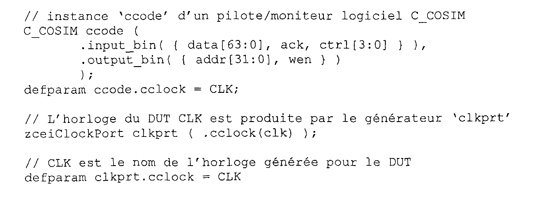

Dans ce fichier d'extension « .dve », les connecteurs 'input_bin' et 'output_bin' du pilote/moniteur C_COSIM n'ont pas de dimension prédéfinie. genFW adapte leur taille en fonction du nombre de signaux qu'il doit connecter.In this ".dve" extension file, the connectors 'input_bin' and 'output_bin' of the C_COSIM driver / monitor did not no predefined dimension. genFW adjusts their size according to the number of signals it needs to connect.
On va maintenant décrire un autre exemple d'utilisation de GenFW.We will now describe another example of the use of GenFW.
Dans cet exemple le circuit DUT à émuler avec le système
d'émulation selon l'invention est un compteur 4 bits décrit en
langage verilog.

L'utilisateur doit alors mettre en oeuvre un outil de synthèse logique (par exemple celui connu sous la dénomination leonardo de la société MENTOR GRAPHICS) pour transformer la description VERILOG du compteur en une netlist EDIF. La netlist EDIF obtenue s'appellera 'counter_4bits.edf' dans la suite de l'exemple.The user must then implement a tool for logical synthesis (for example the one known under the name leonardo of the company MENTOR GRAPHICS) to transform the VERILOG description of the counter in a netlist EDIF. The netlist EDIF obtained will be called 'counter_4bits.edf' in the sequel of the example.
La netlist EDIF 'counter_4bits.edf' sert de point d'entrée décrivant le DUT à la chaíne de compilation XILINX.EDIF netlist 'counter_4bits.edf' serves as a point of entry describing the DUT to the XILINX compilation chain.
Dans cet exemple, l'environnement de test ne comporte
qu'un pilote/moniteur logiciel correspondant à un programme en
C/C++ fait par l'utilisateur.
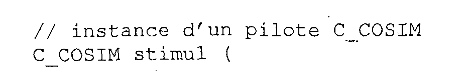

Ce fichier, nommé par exemple 'counter_4bits.dve', signifie que l'utilisateur du système d'émulation selon l'invention veut contrôler la valeur de signal 'rst' de remise à zéro du DUT, ainsi que l'avancement de l'horloge 'clk' dans son programme C/C++.This file, named for example 'counter_4bits.dve', means that the user of the emulation system according to the invention wants to control the signal value 'rst' of delivery to zero of the DUT, as well as the advancement of the clock 'clk' in his C / C ++ program.
Il veut également lire la valeur du signal 'data[3:0]' produite par le DUT dans son programme.He also wants to read the value of the signal 'data [3: 0]' produced by the DUT in its program.
Dans la suite on présente l'utilisation de GenFW sans compilation préalable du DUT avec le logiciel de compilation XILINX.In the following we present the use of GenFW without preliminary compilation of the DUT with the compilation software XILINX.
L'utilisateur peut appeler GenFW avec la commande :
![]()
![]()
Les fichiers d'entrée de genFW sont :
- 'counter_4bits.edf' : la netlist EDIF du DUT,
- 'counter_4bits.dve' : la structure de l'environnement de test.
- 'counter_4bits.edf': the EDIF netlist of the DUT,
- 'counter_4bits.dve': the structure of the test environment.
Les fichiers de sortie sont :
- 'fp_firmware.edf' : la netlist du circuit logique CCL (contenu du circuit reconfigurable CRFG),
- 'fp_firmware.ucf' : les contraintes de placement des entrées-sorties du circuit reconfigurable CRFG,
- 'fp_firmware.xref' : données pour le logiciel de simulation,
- 'counter_4bits.ucf' : les contraintes de placement des entrées-sorties du circuit reconfigurable formant l'émulateur EML,
- 'stimul.c' : fichier C pour la mise en oeuvre du pilote/moniteur de cosimulation dans le programme C/C++ de l'utilisateur.
- 'fp_firmware.edf': the netlist of the CCL logic circuit (content of the CRFG reconfigurable circuit),
- 'fp_firmware.ucf': the input / output placement constraints of the CRFG reconfigurable circuit,
- 'fp_firmware.xref': data for the simulation software,
- 'counter_4bits.ucf': the input / output placement constraints of the reconfigurable circuit forming the EML emulator,
- 'stimul.c': C file for the implementation of the cosimulation driver / monitor in the C / C ++ program of the user.
Le fichier 'counter_4bits.ucf' produit par GenFW contient les contraintes de placement des entrées/sorties du DUT sur les broches du circuit reconfigurable formant l'émulateur EML, qui est par exemple un circuit FPGA désigné dans la suite sous le vocable FPGA DUT.The 'counter_4bits.ucf' file produced by GenFW contains the constraints of placement of the inputs / outputs of the DUT on the reconfigurable circuit pins forming the EML emulator, which is for example an FPGA circuit designated in the following under the term FPGA DUT.
De même dans la suite le circuit reconfigurable CRFG est désigné sous le vocable FPGA FP.Similarly in the following the reconfigurable circuit CRFG is referred to as FPGA FP.
Le format UCF utilisé est un format propriétaire de
XILINX.

Dans ce fichier, AP15, AL16, ..., AH18 sont des noms de broches du FPGA DUT, conformes à la nomenclature de XILINX.In this file, AP15, AL16, ..., AH18 are names of FPGA DUT pins, conforming to the XILINX nomenclature.
GenFW choisi des broches du FPGA DUT qui sont connectées aux banc de test reconfigurable BTR (afin que le banc de test BTR puisse contrôler les entrées/sorties du DUT). De plus, la broche AH18 utilisée pour l'entrée 'clk' est une broche d'horloge du FPGA DUT : GenFW a décidé de placer 'clk' sur l'un des réseaux d'horloges du FPGA DUT à partir de l'instanciation du 'zceiClockPort' dans le fichier 'counter_4bits.dve'.GenFW chose FPGA DUT pins that are connected to the reconfigurable test bench BTR (so that the bench BTR test can control the inputs / outputs of the DUT). Moreover, pin AH18 used for input 'clk' is a pin of the FPGA DUT clock: GenFW decided to place 'clk' on one of the FPGA DUT clock networks from the instantiation of the 'zceiClockPort' in the file 'Counter_4bits.dve.
Dans cet exemple, le FPGA DUT est un circuit VIRTEX-E 1600 à boítier 1156 broches ; les noms des broches choisies par GenFW sont compatibles avec ce type de FPGA. L'utilisation d'un autre modèle de FPGA aurait vraisemblablement abouti à un choix différent des broches. In this example, the FPGA DUT is a VIRTEX-E circuit 1600 to housing 1156 pins; the names of the pins chosen by GenFW are compatible with this type of FPGA. Use another FPGA model would likely have resulted in a different choice of pins.
Le fichier 'fp_firmware.edf' est la netlist EDIF du FPGA FP du banc de test reconfigurable. Elle contient l'instance 'stimul' du pilote/moniteur de cosimulation C 'C_COSIM' conformément à ce qui a été décrit précédemment.The file 'fp_firmware.edf' is the EDIF netlist of FPGA FP of reconfigurable test bench. It contains the instance 'stimul' of the costimulation pilot / monitor C 'C_COSIM' according to what has been described previously.
Le fichier 'fp_firmware.ucf' contient les contraintes de
compilation de la netlist du circuit reconfigurable CRFG par le
logiciel de compilation XILINX. Comme l'indique l'extrait ci-dessous,
les contraintes décrivent le placement des signaux d'entrées-sorties du
circuit logique CCL sur les broches du FPGA FP, mais aussi des
contraintes temporelles telles que la fréquence minimale requise pour
l'horloge système du banc de test reconfigurable.

Dans l'extrait présenté ci-dessus, GenFW a choisi les broches F1, G3, L10, E4 et H7 pour le placement des signaux d'entrées-sorties 'data(3)' ... 'rst' qui doivent être reliés aux signaux de même nom du DUT parce que :
- la broche 'F1' du FPGA FP et reliée à la broche 'AP15' du FPGA DUT
- la broche 'G3' du FPGA FP et reliée à la broche 'AL16' du FPGA DUT
- la broche 'L10' du FPGA FP et reliée à la broche 'AE14' du FPGA DUT
- la broche 'E4' du FPGA FP et reliée à la broche 'AN16' du FPGA DUT
- la broche 'H7' du FPGA FP et reliée à la broche 'AF16' du FPGA DUT.
- the 'F1' pin of the FPGA FP and connected to the 'AP15' pin of the FPGA DUT
- the 'G3' pin of the FPGA FP and connected to the 'AL16' pin of the FPGA DUT
- the 'L10' pin of the FPGA FP and connected to the 'AE14' pin of the FPGA DUT
- the FPGA FP 'E4' pin and connected to the 'AN16' pin of the FPGA DUT
- the 'H7' pin of the FPGA FP and connected to the 'AF16' pin of the FPGA DUT.
Dans cet exemple, le FPGA FP est un circuit VIRTEX-E 1600 à boítier 900 broches ; les noms des broches choisies par GenFW sont compatibles avec ce type de FPGA. L'utilisation d'un autre modèle de FPGA aurait vraisemblablement aboutit à un choix différent des broches.In this example, the FPGA FP is a VIRTEX-E circuit 1600 to 900 pin housing; the names of the pins chosen by GenFW are compatible with this type of FPGA. Use another FPGA model would likely result in a different choice of pins.
Le fichier 'fp_firmware.xref' est destiné à l'interface avec
le logiciel. Il indique les ressources insérées dans le banc de test
reconfigurable permettant le contrôle du système d'émulation par
le programme exécuté sur l'ordinateur hôte.

Ce fichier indique que le banc de test reconfigurable généré par genFW contient 2 ports de communication reliant l'interface du pilote/moniteur logiciel 'stimul' au bus de communication du banc de test reconfigurable .
- port 0 (déclaration $PortSpec_0) : port 'rxp' du pilote/moniteur 'stimul' instancié dans le fichier ".dve"
- port 1 (déclaration $PortSpec_1) : port 'txp' du pilote/moniteur 'stimul' instancié dans le fichier ".dve"
- port 0 (declaration $ PortSpec_0): port 'rxp' of the driver / monitor 'stimul' instantiated in the file ".dve"
- port 1 (declaration $ PortSpec_1): port 'txp' of the driver / monitor 'stimul' instantiated in the file ".dve"
Il indique également que le générateur d'horloge numéro 0
est utilisé pour produire l'horloge du DUT référencée sous le nom
'CLK_ID'.It also indicates that the
On se réfère maintenant à la figure 12a pour décrire un moyen de rétrocontrôle d'horloge MRCH. En effet alors que le circuit sous test et certains pilotes/moniteurs (généralement de type matériel) peuvent fonctionner à des fréquences élevées (10MHz par exemple), d'autres pilotes/moniteurs (généralement de type logiciel) ne peuvent non seulement pas fonctionner à de telles fréquences en mode continu, mais de plus ne peuvent pas stimuler/observer le circuit sous test à une fréquence constante et pré-déterminée. Sur la figure 12a, deux interfaces de pilotes logiciels P1 et P2 fonctionnant en moyenne respectivement à 10kHz et à 500kHz ont été représentées, de même qu'un moniteur matériel émulé Ml pouvant atteindre une fréquence maximale de fonctionnement de 12 MHz.Reference is now made to Figure 12a to describe a MRCH clock feedback means. Indeed while the circuit under test and some pilots / monitors (usually from hardware type) can operate at high frequencies (10MHz for example), other pilots / monitors (usually software type) can not only not work such frequencies in continuous mode but moreover can not to stimulate / observe the circuit under test at a constant frequency and pre-determined. In Figure 12a, two pilot interfaces software P1 and P2 operating on average respectively at 10kHz and 500kHz were represented, as well as a monitor emulated material MI that can reach a maximum frequency of 12 MHz operation.
Il convient donc de prévoir une horloge à « fréquence variable »,c'est à dire qui puisse s'adapter au mieux aux possibilités des pilotes/moniteurs impliqués dans l'environnement de test.It is therefore necessary to provide a clock with "frequency variable, that is to say who can best adapt to possibilities of pilots / instructors involved in the environment test.
Dans l'exemple de la figure 12a, on s'intéresse aux moyens de rétro-contrôles mis en oeuvre pour produire les horloges secondaires synchronisant l'émulateur du circuit sous test et certains pilotes/moniteurs de l'environnement de test. . Dans le cadre du banc de test reconfigurable, ces moyens de rétro-contrôle sont mis en oeuvre par un des générateurs du contrôleur d'horloge CHL du circuit de contrôle CCTL.In the example of Figure 12a, we are interested in the means retro-controls implemented to produce the clocks secondary synchronizing the emulator of the circuit under test and some drivers / monitors from the test environment. . In the framework of the reconfigurable test bench, these means of retro-control are implemented by one of the generators of the clock controller CHL control circuit CCTL.
Plus précisément, les moyens MRCH, composés de portes logiques reçoivent le signal d'horloge driverClock délivré par le diviseur d'horloge DH cadencé par le signal d'horloge de base systemClock. Le facteur de division est déterminé de façon à ce que la fréquence de l'horloge driverClock ne puisse pas dépasser la fréquence maximale de fonctionnement du circuit sous test émulé et des pilotes/moniteurs matériels.More precisely, the MRCH means, consisting of doors logic receive the clock signal driverClock issued by the clock divider DH clocked by the basic clock signal systemClock. The division factor is determined so that that the clock frequency driverClock can not exceed the maximum operating frequency of the circuit under test emulated and hardware drivers / monitors.
Les moyens MRCH reçoivent également deux signaux d'attente w1 et w2 émis par les deux pilotes P1 et P2, et délivrent aux deux pilotes logiciels leurs signaux d'horloge respectifs ckp1, ckp2, et au moniteur matériel Ml et à l'émulateur du circuit sous test EML le signal d'horloge ckEML.The MRCH means also receive two signals waiting w1 and w2 issued by the two pilots P1 and P2, and deliver to the two software drivers their respective clock signals ckp1, ckp2, and the hardware monitor Ml and the circuit emulator under EML test the ckEML clock signal.
La figure 12b montre une table décrivant le comportement des sorties du bloc MRCH en fonction de ses entrées.Figure 12b shows a table describing the behavior outputs of the MRCH block according to its inputs.
Quand le signal d'attente w1 est à 1 (actif), les signaux ckp2 et ckEML sont arrêtés, mais l'horloge ckpl reste encore active (il peut s'agir de l'horloge driverClock directe ou divisée). When the waiting signal w1 is at 1 (active), the signals ckp2 and ckEML are stopped, but the ckpl clock still remains active (this can be the direct or split driverClock clock).
Quand le signal d'attente w2 est à 1 (actif), les signaux ckpl et ckEML sont arrêtés, mais l'horloge ckp2 reste encore active (il peut s'agir de l'horloge driverClock directe ou divisée).When the waiting signal w2 is at 1 (active), the signals ckpl and ckEML are stopped, but the ckp2 clock still remains active (this can be the direct or split driverClock clock).
Lorsque les deux signaux w1 et w2 sont simultanément à 0 (inactifs), toutes les horloges sont actives.When the two signals w1 and w2 are simultaneously 0 (inactive), all clocks are active.
Lorsque les deux signaux w1 et w2 sont simultanément à 1 (actifs), seule l'horloge ckEML est arrêtée.When the two signals w1 and w2 are simultaneously at 1 (active), only the ckEML clock is stopped.
Il est à noter que l'on peut diminuer le nombre de signaux d'horloges utilisées dans l'environnement de test en utilisant des signaux d'activation sur l'horloge driverClock, étant donné que lorsque les horloges secondaires sont actives, elles dérivent toutes de l'horloge driverClock.It should be noted that the number of signals can be reduced clocks used in the test environment by using activation signals on the driverClock clock, since when secondary clocks are active, they all derive clock driverClock.
Ainsi plus généralement le générateur de signaux d'horloges MRCH, synchronisé par l'horloge système de base divisée, délivre différents signaux d'horloge secondaires synchronisant l'émulateur du circuit sous test et certains au moins des moyens matériels du banc de test. Les moyens de rétrocontrôle d'horloge sont alors capables en réponse à au moins un signal d'attente émis par l'un des moyens matériels du banc de test cadencé par un premier signal d'horloge secondaire, d'inhiber temporairement certains des autres signaux d'horloge secondaires de fréquences différentes de celle du premier signal d'horloge secondaire.So more generally the signal generator clocks MRCH, synchronized by the basic system clock divided, delivers different secondary clock signals synchronizing the emulator of the circuit under test and some at least hardware resources of the test bench. The means of clock feedback are then able in response to at least a waiting signal emitted by one of the material means of the bank of test clocked by a first secondary clock signal, to inhibit temporarily some of the other secondary clock signals different frequencies from that of the first clock signal secondary.
Claims (25)
Applications Claiming Priority (2)
| Application Number | Priority Date | Filing Date | Title |
|---|---|---|---|
| FR0207949A FR2841668B1 (en) | 2002-06-26 | 2002-06-26 | METHOD AND SYSTEM FOR EMULATING A TEST CIRCUIT ASSOCIATED WITH A TEST ENVIRONMENT |
| FR0207949 | 2002-06-26 |
Publications (2)
| Publication Number | Publication Date |
|---|---|
| EP1376417A1 true EP1376417A1 (en) | 2004-01-02 |
| EP1376417B1 EP1376417B1 (en) | 2016-09-07 |
Family
ID=29717108
Family Applications (1)
| Application Number | Title | Priority Date | Filing Date |
|---|---|---|---|
| EP03291452.5A Expired - Lifetime EP1376417B1 (en) | 2002-06-26 | 2003-06-16 | Method and system for emulating a circuit under test associated with a test environment |
Country Status (3)
| Country | Link |
|---|---|
| US (2) | US20040111252A1 (en) |
| EP (1) | EP1376417B1 (en) |
| FR (1) | FR2841668B1 (en) |
Cited By (4)
| Publication number | Priority date | Publication date | Assignee | Title |
|---|---|---|---|---|
| EP1600865A1 (en) * | 2004-05-28 | 2005-11-30 | Quickturn Design Systems, Inc. | Dynamic programming of trigger conditions in hardware emulation systems |
| CN101963933A (en) * | 2010-09-29 | 2011-02-02 | 清华大学 | Static instrument matching method adapting to multi-communication protocols in instrument test |
| CN101517391B (en) * | 2006-09-27 | 2011-08-10 | Ifp公司 | System for supervising engine test beds which is independent of the type of engine test bed |
| CN115659885A (en) * | 2022-12-29 | 2023-01-31 | 摩尔线程智能科技(北京)有限责任公司 | System and method for simulation test |
Families Citing this family (34)
| Publication number | Priority date | Publication date | Assignee | Title |
|---|---|---|---|---|
| US7072818B1 (en) | 1999-11-30 | 2006-07-04 | Synplicity, Inc. | Method and system for debugging an electronic system |
| US7065481B2 (en) * | 1999-11-30 | 2006-06-20 | Synplicity, Inc. | Method and system for debugging an electronic system using instrumentation circuitry and a logic analyzer |
| US7222315B2 (en) * | 2000-11-28 | 2007-05-22 | Synplicity, Inc. | Hardware-based HDL code coverage and design analysis |
| US7827510B1 (en) | 2002-06-07 | 2010-11-02 | Synopsys, Inc. | Enhanced hardware debugging with embedded FPGAS in a hardware description language |
| EP1447759A1 (en) * | 2003-02-07 | 2004-08-18 | ARM Limited | Generation of a testbench for a representation of a device |
| US6839242B2 (en) * | 2003-02-13 | 2005-01-04 | Rincon Research Corporation | Reconfigurable circuit modules |
| US7418678B1 (en) * | 2003-12-01 | 2008-08-26 | Jasper Design Automation, Inc. | Managing formal verification complexity of designs with counters |
| US7260798B2 (en) * | 2003-12-29 | 2007-08-21 | Mentor Graphics Corporation | Compilation of remote procedure calls between a timed HDL model on a reconfigurable hardware platform and an untimed model on a sequential computing platform |
| US7257802B2 (en) * | 2003-12-29 | 2007-08-14 | Mentor Graphics Corporation | Method and system for hardware accelerated verification of digital circuit design and its testbench |
| US7305332B1 (en) * | 2004-01-14 | 2007-12-04 | Adaptec, Inc. | System and method for automatic extraction of testing information from a functional specification |
| US8171472B1 (en) * | 2007-08-08 | 2012-05-01 | Sprint Communications Company L.P. | Separation and reuse of versions directory in execution framework installations |
| US7930165B2 (en) * | 2008-02-07 | 2011-04-19 | Accemic Gmbh & Co. Kg | Procedure and device for emulating a programmable unit providing system integrity control |
| CN101996148B (en) * | 2010-09-29 | 2012-07-18 | 清华大学 | Instrument test board configuration method for a plurality of communication protocols |
| TWI450118B (en) * | 2010-11-02 | 2014-08-21 | Global Unichip Corp | Hybrid electronic design system and reconfigurable connection matrix thereof |
| CN104133745A (en) * | 2013-04-30 | 2014-11-05 | 鸿富锦精密工业(深圳)有限公司 | Electronic device with test function, test method and system |
| US9075624B2 (en) * | 2013-06-24 | 2015-07-07 | Xilinx, Inc. | Compilation of system designs |
| US9152520B2 (en) * | 2013-09-26 | 2015-10-06 | Texas Instruments Incorporated | Programmable interface-based validation and debug |
| US9239899B2 (en) | 2014-03-11 | 2016-01-19 | Wipro Limited | System and method for improved transaction based verification of design under test (DUT) to minimize bogus fails |
| ES2864729T3 (en) * | 2014-10-30 | 2021-10-14 | Spherea Test & Services | Bench and software for testing electrical equipment, especially a computer |
| US9773078B2 (en) | 2015-01-22 | 2017-09-26 | Synopsys, Inc. | X-propagation in emulation using efficient memory |
| US9659118B2 (en) | 2015-01-22 | 2017-05-23 | Synopsys, Inc. | X-propagation in emulation |
| CN107250987B (en) * | 2015-01-22 | 2021-01-22 | 美商新思科技有限公司 | X propagation in simulation |
| US9684492B2 (en) | 2015-09-28 | 2017-06-20 | Semmle Limited | Automatic determination of compiler configuration |
| US10185794B2 (en) * | 2015-10-20 | 2019-01-22 | Synopsys, Inc. | Overlaying of clock and data propagation in emulation |
| US10671785B1 (en) * | 2016-12-06 | 2020-06-02 | Xilinx, Inc. | Framework for reusing cores in simulation |
| US10198539B1 (en) * | 2017-03-02 | 2019-02-05 | Cadence Design Systems, Inc. | Systems and methods for dynamic RTL monitors in emulation systems |
| US11194943B2 (en) * | 2017-12-12 | 2021-12-07 | Synopsys, Inc. | FPGA-based hardware emulator system with an inter-FPGA connection switch |
| WO2019167081A1 (en) * | 2018-03-02 | 2019-09-06 | Apasangi Akash | System and method for emulation and simulation of rtl (design under test) using fpga |
| US11080446B2 (en) * | 2019-03-18 | 2021-08-03 | Synopsys, Inc. | Method to regulate clock frequencies of hybrid electronic systems |
| US10990425B2 (en) * | 2019-05-08 | 2021-04-27 | Morgan Stanley Services Group Inc. | Simulated change of immutable objects during execution runtime |
| CN111310313B (en) * | 2020-01-21 | 2023-10-13 | 北京北方华创微电子装备有限公司 | IAP-based simulation method and device and wafer cleaning equipment |
| KR102213842B1 (en) * | 2020-10-20 | 2021-02-08 | 국방과학연구소 | Heterogeneous test equipment for weapon system environment/reliability test, environment test system, and data intermediate apparatus |
| CN116736088B (en) * | 2023-08-11 | 2023-11-17 | 上海类比半导体技术有限公司 | Chip testing method for assisting post-silicon test |
| CN117521583B (en) * | 2023-11-17 | 2024-07-19 | 中科苏州智能计算技术研究院 | Software and hardware joint simulation method and system driven by clock and storage medium |
Citations (1)
| Publication number | Priority date | Publication date | Assignee | Title |
|---|---|---|---|---|
| US6347388B1 (en) * | 1997-06-03 | 2002-02-12 | Verisity Ltd. | Method and apparatus for test generation during circuit design |
Family Cites Families (16)
| Publication number | Priority date | Publication date | Assignee | Title |
|---|---|---|---|---|
| US6389379B1 (en) * | 1997-05-02 | 2002-05-14 | Axis Systems, Inc. | Converification system and method |
| US5960191A (en) * | 1997-05-30 | 1999-09-28 | Quickturn Design Systems, Inc. | Emulation system with time-multiplexed interconnect |
| US6338158B1 (en) * | 1997-10-31 | 2002-01-08 | Vlsi Technology, Inc. | Custom IC hardware modeling using standard ICs for use in IC design validation |
| US6298320B1 (en) * | 1998-02-17 | 2001-10-02 | Applied Microsystems Corporation | System and method for testing an embedded microprocessor system containing physical and/or simulated hardware |
| US6223144B1 (en) * | 1998-03-24 | 2001-04-24 | Advanced Technology Materials, Inc. | Method and apparatus for evaluating software programs for semiconductor circuits |
| US6279146B1 (en) * | 1999-01-06 | 2001-08-21 | Simutech Corporation | Apparatus and method for verifying a multi-component electronic design |
| US6298452B1 (en) * | 1999-02-05 | 2001-10-02 | Hewlett-Packard Company | Hardware test coverage using inter-chip event filtering in multi-chip simulations |
| US6332201B1 (en) * | 1999-03-23 | 2001-12-18 | Hewlett-Packard Company | Test results checking via predictive-reactive emulation |
| US6272451B1 (en) * | 1999-07-16 | 2001-08-07 | Atmel Corporation | Software tool to allow field programmable system level devices |
| US6473726B1 (en) * | 1999-09-24 | 2002-10-29 | Frederic Reblewski | Method and apparatus for concurrent emulation of multiple circuit designs on an emulation system |
| US6611796B1 (en) * | 1999-10-20 | 2003-08-26 | Texas Instruments Incorporated | Method and apparatus for combining memory blocks for in circuit emulation |
| US6678645B1 (en) * | 1999-10-28 | 2004-01-13 | Advantest Corp. | Method and apparatus for SoC design validation |
| US6581191B1 (en) * | 1999-11-30 | 2003-06-17 | Synplicity, Inc. | Hardware debugging in a hardware description language |
| US6587995B1 (en) * | 2000-04-19 | 2003-07-01 | Koninklijke Philips Electronics N.V. | Enhanced programmable core model with integrated graphical debugging functionality |
| US6611936B2 (en) * | 2000-04-28 | 2003-08-26 | Hewlett-Packard Development Company, L.P. | Programmable delay elements for source synchronous link function design verification through simulation |
| GB2381910B (en) * | 2000-05-11 | 2005-03-02 | Quickturn Design Systems Inc | Emulation circuit with a hold time algorithm logic analyzer and shadow memory |
-
2002
- 2002-06-26 FR FR0207949A patent/FR2841668B1/en not_active Expired - Fee Related
-
2003
- 2003-06-16 EP EP03291452.5A patent/EP1376417B1/en not_active Expired - Lifetime
- 2003-06-26 US US10/603,776 patent/US20040111252A1/en not_active Abandoned
-
2009
- 2009-07-22 US US12/507,612 patent/US20100161306A1/en not_active Abandoned
Patent Citations (1)
| Publication number | Priority date | Publication date | Assignee | Title |
|---|---|---|---|---|
| US6347388B1 (en) * | 1997-06-03 | 2002-02-12 | Verisity Ltd. | Method and apparatus for test generation during circuit design |
Non-Patent Citations (2)
| Title |
|---|
| HUTCHINGS B L ET AL: "Unifying simulation and execution in a design environment for FPGA systems", IEEE TRANS. VERY LARGE SCALE INTEGR. (VLSI) SYST. (USA), IEEE TRANSACTIONS ON VERY LARGE SCALE INTEGRATION (VLSI) SYSTEMS, FEB. 2001, IEEE, USA, vol. 9, no. 1, pages 201 - 205, XP002239439, ISSN: 1063-8210 * |
| NEALE R: "Verisity's eCelerator offers test bench synthesis", ELECTRONIC ENGINEERING DESIGN, APRIL 2002, CMP ELECTRONICS GROUP, UK, vol. 74, no. 903, pages 27 - 28, XP008016066, ISSN: 0013-4902 * |
Cited By (6)
| Publication number | Priority date | Publication date | Assignee | Title |
|---|---|---|---|---|
| EP1600865A1 (en) * | 2004-05-28 | 2005-11-30 | Quickturn Design Systems, Inc. | Dynamic programming of trigger conditions in hardware emulation systems |
| US7379861B2 (en) | 2004-05-28 | 2008-05-27 | Quickturn Design Systems, Inc. | Dynamic programming of trigger conditions in hardware emulation systems |
| CN101517391B (en) * | 2006-09-27 | 2011-08-10 | Ifp公司 | System for supervising engine test beds which is independent of the type of engine test bed |
| CN101963933A (en) * | 2010-09-29 | 2011-02-02 | 清华大学 | Static instrument matching method adapting to multi-communication protocols in instrument test |
| CN101963933B (en) * | 2010-09-29 | 2012-11-14 | 清华大学 | Static instrument matching method adapting to multi-communication protocols in instrument test |
| CN115659885A (en) * | 2022-12-29 | 2023-01-31 | 摩尔线程智能科技(北京)有限责任公司 | System and method for simulation test |
Also Published As
| Publication number | Publication date |
|---|---|
| US20040111252A1 (en) | 2004-06-10 |
| FR2841668A1 (en) | 2004-01-02 |
| EP1376417B1 (en) | 2016-09-07 |
| FR2841668B1 (en) | 2006-08-11 |
| US20100161306A1 (en) | 2010-06-24 |
Similar Documents
| Publication | Publication Date | Title |
|---|---|---|
| EP1376417B1 (en) | Method and system for emulating a circuit under test associated with a test environment | |
| JP7053691B2 (en) | Real-time analysis and control for multi-processor systems | |
| US20210081258A1 (en) | Synthesis Path For Transforming Concurrent Programs Into Hardware Deployable on FPGA-Based Cloud Infrastructures | |
| EP0642683B1 (en) | Method and test platforms for the development of an integrated circuit (asic) | |
| EP1387304A1 (en) | Method for functional verification of an integrated circuit model for building a verification platform, emulator equipment and verification platform | |
| CN103324511B (en) | Configure method, programmable device and the machine readable storage medium of programmable device | |
| GB2318664A (en) | Embedded logic analyzer for a programmable logic device | |
| FR2843213A1 (en) | METHOD AND SYSTEM FOR AUTOMATICALLY ESTABLISHING A GLOBAL SIMULATION MODEL OF AN ARCHITECTURE | |
| CN116738901A (en) | Chip verification method and device | |
| JP2731021B2 (en) | ASIC development method, ASIC emulator, integrated circuit design and development method, and single integrated circuit partial development method | |
| FR2916546A1 (en) | METHOD FOR SIMULATING AN ON-BOARD AIRCRAFT ON-BOARD SYSTEM FOR TESTING AN OPERATING SOFTWARE AND DEVICE FOR IMPLEMENTING SAID METHOD | |
| EP0656591B1 (en) | ATE system with integrated bus simulation | |
| EP2956874A2 (en) | Device and method for accelerating the update phase of a simulation kernel | |
| FR3066606A1 (en) | TEST APPARATUS AND METHOD FOR TESTING AN INTEGRATED CIRCUIT | |
| de la Fuente et al. | Building a dynamically reconfigurable system through a high-level development flow | |
| Beserra et al. | Integrating virtual platforms into a heterogeneous MoC-based modeling framework | |
| De La Fuente et al. | Building a dynamically reconfigurable system through a high development flow | |
| Engel | Development of a Read-Out Receiver Card for Fast Processing of Detector Data | |
| CN116451625B (en) | Apparatus and method for joint simulation of RTL and netlist with SDF | |
| de la Fuente et al. | Synthesis of simulation and implementation code for OpenMAX multimedia heterogeneous systems from UML/MARTE models | |
| Tomja | Enhancing Versatility and Efficiency of the CCSDS-123 Compression Algorithm through Dynamic Partial Reconfiguration for the HYPSO Mission | |
| EP1164487A1 (en) | Device for the functional reproduction of a specific intergrated circuit and its usage as an emulation device | |
| US12073155B2 (en) | Method and system for building hardware images from heterogeneous designs for electronic systems | |
| EP1387270B1 (en) | Method and system for automatic recognition of simulation configurations of an integrated circuit | |
| Kritikakis et al. | Enabling dynamic system integration on MAXELER HLS platforms |
Legal Events
| Date | Code | Title | Description |
|---|---|---|---|
| PUAI | Public reference made under article 153(3) epc to a published international application that has entered the european phase |
Free format text: ORIGINAL CODE: 0009012 |
|
| AK | Designated contracting states |
Kind code of ref document: A1 Designated state(s): AT BE BG CH CY CZ DE DK EE ES FI FR GB GR HU IE IT LI LU MC NL PT RO SE SI SK TR |
|
| AX | Request for extension of the european patent |
Extension state: AL LT LV MK |
|
| 17P | Request for examination filed |
Effective date: 20040617 |
|
| AKX | Designation fees paid |
Designated state(s): AT BE BG CH CY CZ DE DK EE ES FI FR GB GR HU IE IT LI LU MC NL PT RO SE SI SK TR |
|
| 17Q | First examination report despatched |
Effective date: 20061229 |
|
| RAP1 | Party data changed (applicant data changed or rights of an application transferred) |
Owner name: SYNOPSYS EMULATION AND VERIFICATION |
|
| REG | Reference to a national code |
Ref country code: DE Ref legal event code: R079 Ref document number: 60349360 Country of ref document: DE Free format text: PREVIOUS MAIN CLASS: G06F0017500000 Ipc: G06F0011260000 |
|
| RIC1 | Information provided on ipc code assigned before grant |
Ipc: G06F 11/26 20060101AFI20160317BHEP Ipc: G06F 17/50 20060101ALI20160317BHEP Ipc: G01R 31/3183 20060101ALI20160317BHEP |
|
| GRAP | Despatch of communication of intention to grant a patent |
Free format text: ORIGINAL CODE: EPIDOSNIGR1 |
|
| INTG | Intention to grant announced |
Effective date: 20160426 |
|
| GRAS | Grant fee paid |
Free format text: ORIGINAL CODE: EPIDOSNIGR3 |
|
| GRAA | (expected) grant |
Free format text: ORIGINAL CODE: 0009210 |
|
| AK | Designated contracting states |
Kind code of ref document: B1 Designated state(s): AT BE BG CH CY CZ DE DK EE ES FI FR GB GR HU IE IT LI LU MC NL PT RO SE SI SK TR |
|
| REG | Reference to a national code |
Ref country code: GB Ref legal event code: FG4D Free format text: NOT ENGLISH |
|
| REG | Reference to a national code |
Ref country code: CH Ref legal event code: EP |
|
| REG | Reference to a national code |
Ref country code: IE Ref legal event code: FG4D Free format text: LANGUAGE OF EP DOCUMENT: FRENCH |
|
| REG | Reference to a national code |
Ref country code: AT Ref legal event code: REF Ref document number: 827422 Country of ref document: AT Kind code of ref document: T Effective date: 20161015 |
|
| REG | Reference to a national code |
Ref country code: DE Ref legal event code: R096 Ref document number: 60349360 Country of ref document: DE |
|
| REG | Reference to a national code |
Ref country code: NL Ref legal event code: MP Effective date: 20160907 |
|
| PG25 | Lapsed in a contracting state [announced via postgrant information from national office to epo] |
Ref country code: FI Free format text: LAPSE BECAUSE OF FAILURE TO SUBMIT A TRANSLATION OF THE DESCRIPTION OR TO PAY THE FEE WITHIN THE PRESCRIBED TIME-LIMIT Effective date: 20160907 |
|
| REG | Reference to a national code |
Ref country code: AT Ref legal event code: MK05 Ref document number: 827422 Country of ref document: AT Kind code of ref document: T Effective date: 20160907 |
|
| PG25 | Lapsed in a contracting state [announced via postgrant information from national office to epo] |
Ref country code: NL Free format text: LAPSE BECAUSE OF FAILURE TO SUBMIT A TRANSLATION OF THE DESCRIPTION OR TO PAY THE FEE WITHIN THE PRESCRIBED TIME-LIMIT Effective date: 20160907 Ref country code: ES Free format text: LAPSE BECAUSE OF FAILURE TO SUBMIT A TRANSLATION OF THE DESCRIPTION OR TO PAY THE FEE WITHIN THE PRESCRIBED TIME-LIMIT Effective date: 20160907 Ref country code: GR Free format text: LAPSE BECAUSE OF FAILURE TO SUBMIT A TRANSLATION OF THE DESCRIPTION OR TO PAY THE FEE WITHIN THE PRESCRIBED TIME-LIMIT Effective date: 20161208 |
|
| PG25 | Lapsed in a contracting state [announced via postgrant information from national office to epo] |
Ref country code: EE Free format text: LAPSE BECAUSE OF FAILURE TO SUBMIT A TRANSLATION OF THE DESCRIPTION OR TO PAY THE FEE WITHIN THE PRESCRIBED TIME-LIMIT Effective date: 20160907 Ref country code: RO Free format text: LAPSE BECAUSE OF FAILURE TO SUBMIT A TRANSLATION OF THE DESCRIPTION OR TO PAY THE FEE WITHIN THE PRESCRIBED TIME-LIMIT Effective date: 20160907 |
|
| PG25 | Lapsed in a contracting state [announced via postgrant information from national office to epo] |
Ref country code: AT Free format text: LAPSE BECAUSE OF FAILURE TO SUBMIT A TRANSLATION OF THE DESCRIPTION OR TO PAY THE FEE WITHIN THE PRESCRIBED TIME-LIMIT Effective date: 20160907 Ref country code: BG Free format text: LAPSE BECAUSE OF FAILURE TO SUBMIT A TRANSLATION OF THE DESCRIPTION OR TO PAY THE FEE WITHIN THE PRESCRIBED TIME-LIMIT Effective date: 20161207 Ref country code: SK Free format text: LAPSE BECAUSE OF FAILURE TO SUBMIT A TRANSLATION OF THE DESCRIPTION OR TO PAY THE FEE WITHIN THE PRESCRIBED TIME-LIMIT Effective date: 20160907 Ref country code: PT Free format text: LAPSE BECAUSE OF FAILURE TO SUBMIT A TRANSLATION OF THE DESCRIPTION OR TO PAY THE FEE WITHIN THE PRESCRIBED TIME-LIMIT Effective date: 20170109 Ref country code: CZ Free format text: LAPSE BECAUSE OF FAILURE TO SUBMIT A TRANSLATION OF THE DESCRIPTION OR TO PAY THE FEE WITHIN THE PRESCRIBED TIME-LIMIT Effective date: 20160907 |
|
| REG | Reference to a national code |
Ref country code: DE Ref legal event code: R097 Ref document number: 60349360 Country of ref document: DE |
|
| PG25 | Lapsed in a contracting state [announced via postgrant information from national office to epo] |
Ref country code: IT Free format text: LAPSE BECAUSE OF FAILURE TO SUBMIT A TRANSLATION OF THE DESCRIPTION OR TO PAY THE FEE WITHIN THE PRESCRIBED TIME-LIMIT Effective date: 20160907 |
|
| PLBE | No opposition filed within time limit |
Free format text: ORIGINAL CODE: 0009261 |
|
| STAA | Information on the status of an ep patent application or granted ep patent |
Free format text: STATUS: NO OPPOSITION FILED WITHIN TIME LIMIT |
|
| PG25 | Lapsed in a contracting state [announced via postgrant information from national office to epo] |
Ref country code: DK Free format text: LAPSE BECAUSE OF FAILURE TO SUBMIT A TRANSLATION OF THE DESCRIPTION OR TO PAY THE FEE WITHIN THE PRESCRIBED TIME-LIMIT Effective date: 20160907 |
|
| 26N | No opposition filed |
Effective date: 20170608 |
|
| PG25 | Lapsed in a contracting state [announced via postgrant information from national office to epo] |
Ref country code: SI Free format text: LAPSE BECAUSE OF FAILURE TO SUBMIT A TRANSLATION OF THE DESCRIPTION OR TO PAY THE FEE WITHIN THE PRESCRIBED TIME-LIMIT Effective date: 20160907 |
|
| PG25 | Lapsed in a contracting state [announced via postgrant information from national office to epo] |
Ref country code: MC Free format text: LAPSE BECAUSE OF FAILURE TO SUBMIT A TRANSLATION OF THE DESCRIPTION OR TO PAY THE FEE WITHIN THE PRESCRIBED TIME-LIMIT Effective date: 20160907 |
|
| REG | Reference to a national code |
Ref country code: CH Ref legal event code: PL |
|
| GBPC | Gb: european patent ceased through non-payment of renewal fee |
Effective date: 20170616 |
|
| REG | Reference to a national code |
Ref country code: IE Ref legal event code: MM4A |
|
| REG | Reference to a national code |
Ref country code: FR Ref legal event code: ST Effective date: 20180228 |
|
| PG25 | Lapsed in a contracting state [announced via postgrant information from national office to epo] |
Ref country code: LI Free format text: LAPSE BECAUSE OF NON-PAYMENT OF DUE FEES Effective date: 20170630 Ref country code: CH Free format text: LAPSE BECAUSE OF NON-PAYMENT OF DUE FEES Effective date: 20170630 Ref country code: GB Free format text: LAPSE BECAUSE OF NON-PAYMENT OF DUE FEES Effective date: 20170616 Ref country code: LU Free format text: LAPSE BECAUSE OF NON-PAYMENT OF DUE FEES Effective date: 20170616 Ref country code: IE Free format text: LAPSE BECAUSE OF NON-PAYMENT OF DUE FEES Effective date: 20170616 |
|
| REG | Reference to a national code |
Ref country code: FR Ref legal event code: PLFP Year of fee payment: 15 |
|
| PG25 | Lapsed in a contracting state [announced via postgrant information from national office to epo] |
Ref country code: FR Free format text: LAPSE BECAUSE OF NON-PAYMENT OF DUE FEES Effective date: 20170630 |
|
| REG | Reference to a national code |
Ref country code: FR Ref legal event code: RN Effective date: 20180511 Ref country code: BE Ref legal event code: MM Effective date: 20170630 |
|
| PG25 | Lapsed in a contracting state [announced via postgrant information from national office to epo] |
Ref country code: BE Free format text: LAPSE BECAUSE OF NON-PAYMENT OF DUE FEES Effective date: 20170630 |
|
| REG | Reference to a national code |
Ref country code: FR Ref legal event code: PLFP Year of fee payment: 16 |
|
| REG | Reference to a national code |
Ref country code: FR Ref legal event code: FC Effective date: 20181009 |
|
| REG | Reference to a national code |
Ref country code: GB Ref legal event code: S28 Free format text: APPLICATION FILED |
|
| REG | Reference to a national code |
Ref country code: GB Ref legal event code: S28 Free format text: RESTORATION ALLOWED Effective date: 20190102 |
|
| PG25 | Lapsed in a contracting state [announced via postgrant information from national office to epo] |
Ref country code: FR Free format text: LAPSE BECAUSE OF NON-PAYMENT OF DUE FEES Effective date: 20170630 |
|
| PGRI | Patent reinstated in contracting state [announced from national office to epo] |
Ref country code: FR Effective date: 20181009 |
|
| PG25 | Lapsed in a contracting state [announced via postgrant information from national office to epo] |
Ref country code: HU Free format text: LAPSE BECAUSE OF FAILURE TO SUBMIT A TRANSLATION OF THE DESCRIPTION OR TO PAY THE FEE WITHIN THE PRESCRIBED TIME-LIMIT; INVALID AB INITIO Effective date: 20030616 |
|
| PG25 | Lapsed in a contracting state [announced via postgrant information from national office to epo] |
Ref country code: SE Free format text: LAPSE BECAUSE OF NON-PAYMENT OF DUE FEES Effective date: 20160907 |
|
| PG25 | Lapsed in a contracting state [announced via postgrant information from national office to epo] |
Ref country code: CY Free format text: LAPSE BECAUSE OF NON-PAYMENT OF DUE FEES Effective date: 20160907 |
|
| PG25 | Lapsed in a contracting state [announced via postgrant information from national office to epo] |
Ref country code: TR Free format text: LAPSE BECAUSE OF FAILURE TO SUBMIT A TRANSLATION OF THE DESCRIPTION OR TO PAY THE FEE WITHIN THE PRESCRIBED TIME-LIMIT Effective date: 20160907 |
|
| PGFP | Annual fee paid to national office [announced via postgrant information from national office to epo] |
Ref country code: GB Payment date: 20220519 Year of fee payment: 20 Ref country code: FR Payment date: 20220519 Year of fee payment: 20 Ref country code: DE Payment date: 20220518 Year of fee payment: 20 |
|
| REG | Reference to a national code |
Ref country code: DE Ref legal event code: R071 Ref document number: 60349360 Country of ref document: DE |
|
| REG | Reference to a national code |
Ref country code: GB Ref legal event code: PE20 Expiry date: 20230615 |
|
| P01 | Opt-out of the competence of the unified patent court (upc) registered |
Effective date: 20230528 |
|
| PG25 | Lapsed in a contracting state [announced via postgrant information from national office to epo] |
Ref country code: GB Free format text: LAPSE BECAUSE OF EXPIRATION OF PROTECTION Effective date: 20230615 |