EP1376286A2 - Vorrichtung und Verfahren zum Überwachen eines ablaufenden Prozesses - Google Patents
Vorrichtung und Verfahren zum Überwachen eines ablaufenden Prozesses Download PDFInfo
- Publication number
- EP1376286A2 EP1376286A2 EP20030012819 EP03012819A EP1376286A2 EP 1376286 A2 EP1376286 A2 EP 1376286A2 EP 20030012819 EP20030012819 EP 20030012819 EP 03012819 A EP03012819 A EP 03012819A EP 1376286 A2 EP1376286 A2 EP 1376286A2
- Authority
- EP
- European Patent Office
- Prior art keywords
- main component
- information
- vector
- measurement
- transformation
- Prior art date
- Legal status (The legal status is an assumption and is not a legal conclusion. Google has not performed a legal analysis and makes no representation as to the accuracy of the status listed.)
- Granted
Links
Images


Classifications
-
- G—PHYSICS
- G05—CONTROLLING; REGULATING
- G05B—CONTROL OR REGULATING SYSTEMS IN GENERAL; FUNCTIONAL ELEMENTS OF SUCH SYSTEMS; MONITORING OR TESTING ARRANGEMENTS FOR SUCH SYSTEMS OR ELEMENTS
- G05B23/00—Testing or monitoring of control systems or parts thereof
- G05B23/02—Electric testing or monitoring
- G05B23/0205—Electric testing or monitoring by means of a monitoring system capable of detecting and responding to faults
- G05B23/0218—Electric testing or monitoring by means of a monitoring system capable of detecting and responding to faults characterised by the fault detection method dealing with either existing or incipient faults
- G05B23/0224—Process history based detection method, e.g. whereby history implies the availability of large amounts of data
- G05B23/024—Quantitative history assessment, e.g. mathematical relationships between available data; Functions therefor; Principal component analysis [PCA]; Partial least square [PLS]; Statistical classifiers, e.g. Bayesian networks, linear regression or correlation analysis; Neural networks
Definitions
- the present invention relates to monitoring of processes.
- sensors are used for process measurement technology Measurement of respective parameters used. These sensors can Conductivity sensors that are a conductivity for example ohmic, using voltammetry or potentiometry measure up. Furthermore, sensors for measuring the optical properties, for example by means of transmitted light, Scattered light, surface reflection measurement or spectroscopy used. Others used in the prior art Sensors include sensors to measure viscosity, the permittivity, for example by detecting the impedance or impedance spectroscopy, a temperature, a Thermal conductivity, heat capacity or chemical Sensors of all kinds. It is usually irrelevant whether the sensors in a conventional way or are constructed using microsystems technology. There is also an installation the sensors are not critical, provided the installation location for measurement relevant properties is suitable.
- the object of the present invention is a Device and method to create a stable Monitoring of ongoing processes.
- This task is accomplished through a method of monitoring a Process according to claim 1 and a device for monitoring a process according to claim 9 solved.
- the present invention is based on the finding that this marks an end to a discontinuous process is that the process parameters no longer change and only due to statistical fluctuations or Cross effects are affected.
- a sensitive observation this saturation process is achieved by a Major component analysis is performed in one single-stage or multi-stage process from the sensor data is calculated. This creates a trajectory of the measurement vectors, which contain all sensor signals after the main component transformation end in a saturation point. According to the invention become consecutive in the main component space Measuring vectors compared to one another Gain indicator size.
- main component measurement vectors When comparing the measurement vectors in the main component space, which are also referred to below as main component measurement vectors different criteria can be applied come.
- the distance two successive main component measurement vectors each used.
- metrics such as a Euclidean metric or a Mahalanobis distance available.
- Direction criterion is called the direction of a difference vector of the main component measurement vectors to be compared in each case serve.
- a selection of the measurement vectors for the Major component analysis can be used, for example every second measurement vector to be used. It is also possible averaging a predetermined number of Perform measurement vectors, so that a main component transformation using only the averages is carried out.
- one or more others Criteria for creating one or more others Indicator sizes are used.
- a criterion can be, for example, the length of time until an end state is achieved.
- the further indicator size can, for example serve to determine a decision whether a further process step is necessary and what type this further process step is.
- a single one of the criteria described above or a combination of the criteria becomes an absolute value and preferably an average absolute value the distance criterion and the direction criterion used to make a determination of whether another Process step is necessary.
- the measurement data of the measurement vectors can be sensor data of one or several known sensors, such as optical, capacitive, amperometric or chemical sensors. Furthermore, the sensor data can also be obtained from a multi-sensor system be won.
- the measurement data of the measurement vectors can be standardized before the main components. Typically, the mean is normalized to 0 and the variance to 1. The normalization can be carried out for the data recorded up to the time of the respective main component transformation or in a fixed manner which is retained for all data recorded during the entire process. Which of the standardizations is used in a process must be decided depending on the case.
- the sensor data can be transient sensor signals, such as a spectrum or a temperature. Furthermore, the sensor data can also include data from a time series measurement.
- An advantage of the present invention is that prior knowledge of the process is not necessary, to extract the main components or features. Further is due to the successive execution of the main component analysis no calibrated main component system necessary. Furthermore, through regular recalculation Problems caused by sensor drifts, unexpected cross influences etc. can arise if these are too far from deviate from the original calibration, avoided.
- the selection of the sensor system can be based either on the Process knowledge or based on formal criteria, such as an impact on the outcome from the first Sub-matrix of the main component transformation (loads) is determinable.
- a multi-stage Main component transformation for the combination of sensor data different dimensions can be used.
- the device 100 comprises a detection device 110, which with a Main component transformer 112 connected is.
- the detection device 110 is designed to detect the Main component transformer 112 information of the process, which can be measurement data, for example, to deliver.
- the measurement information can be one or more Components of a measurement vector are understood, whereby the different components have different dimensions can have. For example, impedance spectroscopy for a measurement vector 35 impedance measurements can be detected at different frequencies, in one Measurement vector also a logarithmic representation of the measurement values can be chosen.
- Detector 110 may be a sensor, such as a sensor for measuring conductivity, optical Properties, a viscosity, a permittivity a temperature, a thermal conductivity, a heat capacity or chemical properties. Furthermore, the Detection device 110 also only an interface or include an input to measurement signals or measurement data of a sensor.
- the main component transformation device 112 is furthermore connected to an evaluation device 114.
- the main component transformation device 112 can for example include a processor in which appropriate principal component transformation techniques can be done so that a main component measurement vector from the measurement vector is generated in a main component space.
- the evaluation device 114 can also be a processor which share a common processor can.
- the operation is as follows the control device 100 explained in more detail by way of example.
- measurement data is recorded, which preferably all relevant and physical Record parameters of the process to be monitored. It is important to ensure that there is a sufficient number relevant sensors or sensor data is available, because the stability of the process depends, among other things, on its relevance and quality of the data is dependent.
- the capture the measuring vectors are at successive intervals, which can be selected depending on the process type, repeated carried out.
- Step 210 performed a major component analysis.
- a main component transformation is a mathematical process in which using the entered Data using multivariate statistics Main components or characteristics are extracted and the input measurement vectors in a main component space be transformed. Further explanations regarding the Basics of the main component transformation can be found for example in EP 1 143 240 A1.
- the main component analysis provides for a monitoring or Tax procedures a suitable means is available to extract the features without a priori Knowledge of the process either at the operating personnel or is implicitly necessary in the algorithms used. It is preferred to calculate the main component transformation uses a nipals algorithm that is a special one quick calculation allowed.
- the principal component analysis we prefer all available up to the calculation time standing measurement vectors are used. However, it can a selection of the measurement vectors is also made, that, for example, only the last n measurement vectors be used. A selection can also go further be taken that certain measurement vectors for the main component analysis are filtered out, for example using only every second measurement vector becomes. This is particularly advantageous if one Reduction of the measurement vectors to accelerate the main component transformation to be carried out. Further can also be a reduction of the measurement vectors by means of formation of mean values can be achieved. As an example here, for example, the calculation of a moving average genannnt.
- the main component transformation is preferably such performed a transformation on the eigenvectors only for the most important main components, whereby the rank of importance according to the variance of the measurement vectors directed.
- the transformation only for the first two main components or the first five Main components are carried out.
- a selection can also be made in the case of the main component transformation used main components performed , for example by adding the first, third and fifth main component is used.
- the detected measurement vectors are respective main component measurement vectors representable in the main component dream.
- the main component transformations can also be a combination of sensor signals of different dimensions include.
- the measurement vectors can each from a spectrum, a conductance, a temperature and an optical absorption.
- a multi-stage main component transformation for use get, in which the main components from the measurement vectors and with components of different dimensions be calculated.
- preprocessing can also be done the measurement data for dimension reduction before the main component transformation respectively.
- a Fourier transform can be used and uses a wavelet transform become.
- the main component transformation is carried out in a continuous manner, such that after a certain elapsed time, or in other words after a certain number of newly acquired measurement vectors, one new major component transformation using the newly acquired measurement vectors is carried out.
- the times each new main component transformations can be predetermined or determined during the course of the process or be modified.
- a batch process typically takes place first a major change in one or several parameters of the process.
- a process is understood with at least one parameter at the end the process no longer changes or only statistically fluctuates.
- a batch process can also include multiple sub-processes that are themselves discontinuous again are.
- a comparison of the main component measurement vectors was carried out and calculates a process indicator size.
- the main component measurement vector calculated immediately before compared and from them a process indicator size calculated.
- a process indicator size calculated.
- several can also be used previously calculated main component measurement vectors for Calculation of the process indicator size can be used.
- the distance criterion is the distance of the compared Main component measurement vectors, i.e. the amount of Difference vector resulting from the difference thereof, determined and used as process indicator size. This can be done using various metrics such as the Euclidean metric or the Mahalanobis Distance. If the process is at the end, so strive for the calculated distances of the main component vectors either zero or another value to. As explained in more detail below, this can be done will be used to make a decision as to whether and what intervention will be made in the process should.
- the direction criterion also offers a suitable means of recognizing the end of the Process.
- the direction criterion is the direction of the respective difference vector of the main component measurement vectors calculated as process indicator size.
- the two Criteria are carried out. For example, this can by means of an average absolute value. It at this point it should be noted that the above criteria represents only a selection that the comparison of the main component measurement vectors for calculating a Process indicator size can serve.
- the main component analysis can be performed on selected calibration processes be carried out so that for evaluation the main component transformation calculated on this calibration is used. Because of the successive However, performing the principal component analysis is a such a calibrated main component system is not necessarily required.
- the process indicator size comprise several components, a first Size, for example, for deciding whether to add another Process step to be performed is relevant while a second component of the process indicator size for the selection of the process step to be carried out is relevant is.
- step 230 a detection of an end the process using the process indicator size carried out.
- the recognition can be, for example, that it is determined whether a predetermined number of process indicator sizes in a predetermined indicator range lies.
- a difference method can also be used here at which successive process indicator sizes to be compared to one another Determine change in process indicator sizes.
- a decision is also made in the process whether an intervention in the process is to be carried out.
- a decision-making process can, for example be that an intervention is made when a predetermined one Number of process indicator sizes in a predetermined one Indicator area lies.
- FIG. 3 shows a course of indicator sizes in one Diagram with a first main component on an x-axis is plotted while a second is on a y-axis Main component is applied.
- the course shown shows a projection of a trajectory of a Main component measurement vector in the plane of these first two Main components.
- a diagram is as follows that explains the time course of the calculated process indicator represents.
- the diagram is on an x-axis plotted the time in minutes while on a y-axis the process indicator size in units of the Mahalanobis distance (arbitrary units) is shown.
- FIGS. 3 and 4 The process represented by FIGS. 3 and 4 is concerned it is a cleaning process with lye, in which by the method according to the invention the change of the covering recognized and the cleaning controlled accordingly should be, as will be explained in more detail below.
- the one plotted in the graph of FIG Process indicator size can be interpreted as a coating indicator.
- the process indicator size was used in this exemplary Example of a Mahalanobis distance between two successive ones Measurement vectors calculated.
- a reference value 400 denotes a threshold value, the one to decide about performing one Process intervention is used. A permanent shortfall this threshold indicates that cleaning is finished.
- the end of the process can be recognized, whereupon appropriate control measures to intervene in the cleaning process can be carried out.
- the structure is as follows for controlling a cleaning process in a pipeline in which the data shown in Figs. 3 and 4 won.
- Fig. 5 shows a sensor in this embodiment an interdigital capacitor, whose impedance depends on a deposit deposited on it. For use comes an impedance spectroscopy that enables to detect a sensor signal.
- the interdigital capacitor 500 has a known structure in which a dielectric substrate 510 a first comb electrode assembly 512 and a second comb electrode arrangement 514 having.
- the interdigital capacitor also has a Protective layer 516 made of SiC, which has a chemical and mechanical Protection for the sensor provides.
- the protective layer 516 defines the active surface of the Sensor.
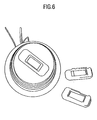
- FIG. 6 also shows how the sensor described in FIG. 5 can be built into an adapter plate to cover the surface recognizable in the pipeline and a corresponding Control of the cleaning process.
Landscapes
- Physics & Mathematics (AREA)
- Engineering & Computer Science (AREA)
- Artificial Intelligence (AREA)
- Evolutionary Computation (AREA)
- Mathematical Physics (AREA)
- General Physics & Mathematics (AREA)
- Automation & Control Theory (AREA)
- Testing Or Calibration Of Command Recording Devices (AREA)
- Testing And Monitoring For Control Systems (AREA)
Abstract
Description
Bei den Sensordaten kann es sich um transiente Sensorsignale, wie beispielsweise ein Spektrum oder eine Temperatur, handeln. Ferner können die Sensordaten auch Daten einer Zeitreihenmessung umfassen.
- Fig. 1
- eine schematische Darstellung eines Auführungsbeispiels einer Steuervorrichtung gemäß der vorliegenden Erfindung;
- Fig. 2
- ein Verfahrensdiagramm zum Darstellen eines Steuerungsablaufs gemäß einem Ausführungsbeispiel der vorliegenden Erfindung;
- Fig. 3
- eine Darstellung einer Trajektorie, die in die Ebene der ersten beiden Hauptkomponenten des Hauptkomponententraums projiziert ist;
- Fig. 4
- ein Schaubild, bei dem ein exemplarischer Verlauf einer berechneten Indikatorgröße gegen die Zeit dargestellt ist;
- Fig. 5
- eine schematische Darstellung eines InterdigitalKondenstor-Sensor zur Belagerkennung, der als ein Sensor zum Liefern von Daten zum Durchführen einer Überwachung eines Reinigungsprozesses verwendbar ist;.
- Fig. 6
- eine Darstellung eines Einbaus eines Sensors zur Belagerkennung in einer Anlage.
Claims (19)
- Verfahren zum Überwachen eines Prozesses mit folgenden Schritten:Wiederholtes Erfassen (200) von zumindest zwei unterschiedlichen Informationen des Prozesses;Durchführen (210) einer Hauptkomponententransformation aufgrund der erfaßten Informationen ohne Verwendung von vor dem Überwachungsverfahren erfaßten Informationen, um einen Hauptkomponenten-Meßvektor in einem Hauptkomponentenraum zu berechnen;Berechnen (220) einer Prozeßindikatorgröße unter Verwendung des berechneten Hauptkomponenten-Meßvektor und einem oder mehreren vorhergehend berechneten Hauptkomponenten-Meßvektoren; undErkennen (230) eines Prozeßendes unter Verwendung der Prozeßindikatorgröße.
- Verfahren nach Anspruch 1, bei dem der Prozeß ein diskontinuierlich ablaufender Prozeß ist.
- Verfahren nach Anspruch 1 oder 2, bei dem der Schritt des wiederholten Erfassens (200) ein Erfassen von zumindest zwei unterschiedlichen Meßdaten des Prozesses aufweist.
- Verfahren nach einem der Ansprüche 1 bis 3, bei dem der Schritt des Durchführens (210) einer Hauptkomponententransformation ferner den Schritt eines Auswählens der erfaßten Informationen umfaßt, um lediglich für die ausgewählten Informationen eine Hauptkomponententransformation durchzuführen.
- Verfahren nach einem der Ansprüche 1 bis 4, bei dem der Schritt des Durchführens (210) einer Hauptkomponententransformation ferner ein Mitteln der erfaßten Informationen zum Erzeugen von Mittelwertinformationen, die bei der Hauptkomponententransformation verwendet werden, umfaßt.
- Verfahren nach einem der Ansprüche 1 bis 5, bei dem der Schritt des Berechnens (220) einer Prozeßindikatorgröße das Berechnen eines Betrags und/oder einer Richtung eines Differenzvektors umfaßt, der aus dem berechneten Hauptkomponenten-Meßvektor und einem vorhergehenden Hauptkomponenten-Meßvektor gebildet wird.
- Verfahren nach einem der Ansprüche 1 bis 6, bei dem in dem Schritt des Erkennens (230) eines Prozeßendes das Ende des Prozesses angezeigt wird, wenn eine vorbestimmte Anzahl von Prozeßindikatorgrößen in einem vorbestimmten Indikatorbereich liegt.
- Verfahren nach einem der Ansprüche 1 bis 7, das ferner den Schritt eines Eingreifens in den ablaufenden Prozeß umfaßt, wenn bei dem Schritt des Erkennens eines Prozeßendes ein Ende des ablaufenden Prozesses erkannt wird.
- Vorrichtung (100) zum Überwachen eines ablaufenden Prozesses mit folgenden Merkmalen:einer Erfassungseinrichtung (110) zum wiederholten Erfassen von zumindest zwei unterschiedlichen Informationen des Prozesses;einer Einrichtung (112) zum Durchführen einer Hauptkomponententransformation aufgrund der erfaßten Informationen, wodurch ein Hauptkomponenten-Meßvektor in einem Hauptkomponententraum berechnet wird; undeiner Auswerteeinrichtung (114) zum Berechnen einer Prozeßindikatorgröße unter Verwendung des berechneten Hauptkomponenten-Meßvektors und einem oder mehreren vorhergehend berechneten Hauptkomponenten-Meßvektoren, wobei die Auswerteeinrichtung (114) ferner ausgebildet ist, um ein Ende des Prozesses unter Verwendung der Prozeßindikatorgröße zu erkennen.
- Vorrichtung (100) nach Anspruch 9, bei der die Erfassungseinrichtung (110) eine oder mehrere Sensoren umfaßt, die aus der Gruppe ausgewählt sind, die einen optischen Sensor, einen kapazitiven Sensor, einen amperometrischen Sensor, einen Temperatursensor und einen chemischen Sensor umfaßt.
- Vorrichtung nach Anspruch 9 oder 10, bei der die Einrichtung (112) zum Durchführen einer Hauptkomponententransformation ferner ausgebildet ist, um aus den erfaßten Informationen des Prozesses eine Auswahl zu treffen, so daß eine Hauptkomponententransformation lediglich für die ausgewählten Informationen des Prozesses durchgeführt wird.
- Vorrichtung (100) nach einem der Ansprüche 9 bis 11, bei der die Einrichtung (112) zum Durchführen einer Hauptkomponententransformation ferner ausgebildet ist, um eine Hauptkomponententransformation unter Verwendung von Mittelwertinformationen durchzuführen, die durch Mittelung der erfaßten Informationen des Prozesses gebildet werden.
- Vorrichtung (100) nach einem der Ansprüche 9 bis 12, bei der die Auswerteeinrichtung ausgebildet ist, um die Prozeßindikatorgröße unter Verwendung eines Abstands des berechneten Hauptkomponenten-Meßvektors von einem vorhergehenden Hauptkomponenten-Meßvektor und/oder einer Richtung eines Differenzvektors aus dem berechneten Vektor und einem vorhergehenden Vektor zu berechnen.
- Vorrichtung (100) nach Anspruch 13, bei dem die Prozeßindikatorgröße aus den Absolutwerten des Abstands und der Richtung des Differenzvektors berechnet wird.
- Vorrichtung (100) nach einem der Ansprüche 9 bis 14, bei der die Erfassungseinrichtung (110) ausgebildet ist, um transiente Meßsignale zu erfassen.
- Vorrichtung (100) nach Anspruch 15, bei der die transienten Meßsignale ein Spektrum oder ein Temperatursignal umfassen.
- Vorrichtung (100) nach einem der Ansprüche 9 bis 16, bei der die Erfassungseinrichtung ausgebildet ist, um Zeitreiheninformationen zu erfassen.
- Vorrichtung (100) nach einem der Ansprüche 9 bis 17, bei der die Erfassungseinrichtung ausgebildet ist, um zumindest zwei unterschiedliche Parameter unterschiedlicher Dimensionalität zu erfassen und wobei die Einrichtung (112) zum Durchführen einer Hauptkomponententransformation ausgebildet ist, um eine mehrstufige Hauptkomponententransformation aufgrund der zumindest zwei unterschiedlichen Parameter unterschiedlicher Dimensionalität durchzuführen.
- Vorrichtung (100) nach einem der Ansprüche 9 bis 18, die ferner eine Steuereinrichtung aufweist, um in den ablaufenden Prozeß einzugreifen, wenn durch die Auswerteeinrichtung ein Ende des Prozesses erkannt wird.
Applications Claiming Priority (2)
| Application Number | Priority Date | Filing Date | Title |
|---|---|---|---|
| DE10228799 | 2002-06-27 | ||
| DE10228799A DE10228799A1 (de) | 2002-06-27 | 2002-06-27 | Vorrichtung und Verfahren zum Überwachen eines ablaufenden Prozesses |
Publications (3)
| Publication Number | Publication Date |
|---|---|
| EP1376286A2 true EP1376286A2 (de) | 2004-01-02 |
| EP1376286A3 EP1376286A3 (de) | 2004-05-12 |
| EP1376286B1 EP1376286B1 (de) | 2006-02-15 |
Family
ID=29716689
Family Applications (1)
| Application Number | Title | Priority Date | Filing Date |
|---|---|---|---|
| EP03012819A Expired - Lifetime EP1376286B1 (de) | 2002-06-27 | 2003-06-05 | Vorrichtung und Verfahren zum Überwachen eines ablaufenden Prozesses |
Country Status (3)
| Country | Link |
|---|---|
| US (1) | US7013237B2 (de) |
| EP (1) | EP1376286B1 (de) |
| DE (2) | DE10228799A1 (de) |
Families Citing this family (3)
| Publication number | Priority date | Publication date | Assignee | Title |
|---|---|---|---|---|
| EP2002013A4 (de) | 2006-04-04 | 2010-05-05 | Labonnet Ltd | Beurteilung der reaktionskinetik-kompatibilität zwischen polymerasekettenreaktionen |
| JP5007964B2 (ja) * | 2010-05-13 | 2012-08-22 | 横河電機株式会社 | 化学センサの校正装置 |
| WO2018084853A1 (en) * | 2016-11-04 | 2018-05-11 | Halliburton Energy Services, Inc. | Universal downhole fluid analyzer with generic inputs |
Family Cites Families (10)
| Publication number | Priority date | Publication date | Assignee | Title |
|---|---|---|---|---|
| US5568400A (en) * | 1989-09-01 | 1996-10-22 | Stark; Edward W. | Multiplicative signal correction method and apparatus |
| US5267277A (en) * | 1989-11-02 | 1993-11-30 | Combustion Engineering, Inc. | Indicator system for advanced nuclear plant control complex |
| SE9304246L (sv) * | 1993-12-22 | 1995-06-23 | Asea Brown Boveri | Förfarande vid övervakning av multivariata processer |
| GB2321720A (en) | 1997-02-04 | 1998-08-05 | Secr Defence | Modelling a system with more parameters than sensors |
| DE19743600B4 (de) * | 1997-10-02 | 2006-03-23 | Fraunhofer-Gesellschaft zur Förderung der angewandten Forschung e.V. | Verfahren zur Überwachung eines zyklischen Produktionsprozesses |
| DE19755133A1 (de) | 1997-12-11 | 1999-06-24 | Siemens Ag | Verfahren zur Überwachung von Bearbeitungsanlagen |
| DE10114206A1 (de) * | 2000-03-23 | 2001-11-29 | Simsci Ltd Invensys House Lond | Überwachung und Steuerung von Prozessen unter Verwendung selbstüberprüfender Sensoren |
| JP4397104B2 (ja) | 2000-05-26 | 2010-01-13 | いすゞ自動車株式会社 | 特性値同定方法及び装置 |
| US6636842B1 (en) | 2000-07-15 | 2003-10-21 | Intevep, S.A. | System and method for controlling an industrial process utilizing process trajectories |
| DE10112352A1 (de) * | 2001-03-13 | 2002-09-19 | Philips Corp Intellectual Pty | Anordnung zur Winkelmessung |
-
2002
- 2002-06-27 DE DE10228799A patent/DE10228799A1/de not_active Withdrawn
-
2003
- 2003-06-05 EP EP03012819A patent/EP1376286B1/de not_active Expired - Lifetime
- 2003-06-05 DE DE50302396T patent/DE50302396D1/de not_active Expired - Lifetime
- 2003-06-26 US US10/606,912 patent/US7013237B2/en not_active Expired - Fee Related
Also Published As
| Publication number | Publication date |
|---|---|
| DE50302396D1 (de) | 2006-04-20 |
| EP1376286A3 (de) | 2004-05-12 |
| US7013237B2 (en) | 2006-03-14 |
| US20040059516A1 (en) | 2004-03-25 |
| EP1376286B1 (de) | 2006-02-15 |
| DE10228799A1 (de) | 2004-01-29 |
Similar Documents
| Publication | Publication Date | Title |
|---|---|---|
| DE69113164T2 (de) | Verfahren und Vorrichtung für die Steuerung eines Prozesses. | |
| DE69930501T2 (de) | Ultrasensitive überwachung von sensoren und prozessen | |
| EP4165484B1 (de) | Überwachungsvorrichtung und verfahren zur anomaliedetektion | |
| EP3210088B1 (de) | Verfahren und assistenzsystem zur erkennung einer störung in einer anlage | |
| DE102018009309B4 (de) | Numerisches Steuergerät | |
| EP4108411B1 (de) | Verfahren, system und computerprogrammprodukt zum überwachen eines formgebungsprozesses | |
| DE69713600T2 (de) | System zur überwachung und diagnose von automatischen regelschleifen | |
| WO2018141702A1 (de) | Verfahren zum bereitstellen von messwerten einer technischen anlage, technisches system und verfahren zum betreiben des technischen systems | |
| DE10222187A1 (de) | Verfahren und Vorrichtung zum Bestimmen von Restnutzungsintervallen | |
| EP1376286B1 (de) | Vorrichtung und Verfahren zum Überwachen eines ablaufenden Prozesses | |
| DE102022105157A1 (de) | Zustandsdiagnosesystem | |
| EP2725312A2 (de) | Verfahren und Vorrichtung zum Überwachen einer Kältemittelfüllmenge | |
| EP4356209B1 (de) | Überwachung der produktion von werkstoffplatten, insbesondere holzwerkstoffplatten, insbesondere unter verwendung einer selbstorganisierenden karte | |
| DE102019004502A1 (de) | Verfahren zum Bestimmen und Angeben der Reststandzeit eines Filters | |
| DE102019214009B3 (de) | Analyse von Sensormessdaten eines Roboters oder Manipulators | |
| DE112021008086B4 (de) | Zustandserfassungssystem, zustandserfassungsverfahren und zustandserfassungsprogramm | |
| EP3926636A2 (de) | Verfahren zum erkennen einer amplifikationsphase in einer amplifikation | |
| DE102018133232A1 (de) | Verfahren zur Überwachung eines Prozesses | |
| WO2020035191A1 (de) | Vorrichtung mit einer sensoreinheit und einer selbstkalibrierungsfunktion | |
| EP4254109B1 (de) | Zustandsbewertung eines systems | |
| DE102018128640A1 (de) | Vorrichtung zur Einschätzung einer Rauscherzeugungsursache | |
| EP2154529A2 (de) | Verfahren zur Auswertung von Gassensorsignalen | |
| DE102017216749A1 (de) | Verfahren zur Bereitstellung eines Steuersignals | |
| DE10225343A1 (de) | Verfahren zur Erkennung von Ausreißern in einer Folge von digitalisierten Messwerten | |
| DE102006003611A1 (de) | Verfahren zum Auffinden eines fehlerhaften Datensatzes in einer Datensatzmenge |
Legal Events
| Date | Code | Title | Description |
|---|---|---|---|
| PUAI | Public reference made under article 153(3) epc to a published international application that has entered the european phase |
Free format text: ORIGINAL CODE: 0009012 |
|
| AK | Designated contracting states |
Kind code of ref document: A2 Designated state(s): AT BE BG CH CY CZ DE DK EE ES FI FR GB GR HU IE IT LI LU MC NL PT RO SE SI SK TR |
|
| AX | Request for extension of the european patent |
Extension state: AL LT LV MK |
|
| PUAL | Search report despatched |
Free format text: ORIGINAL CODE: 0009013 |
|
| AK | Designated contracting states |
Kind code of ref document: A3 Designated state(s): AT BE BG CH CY CZ DE DK EE ES FI FR GB GR HU IE IT LI LU MC NL PT RO SE SI SK TR |
|
| AX | Request for extension of the european patent |
Extension state: AL LT LV MK |
|
| 17P | Request for examination filed |
Effective date: 20041013 |
|
| AKX | Designation fees paid |
Designated state(s): DE FR GB IT SE |
|
| 17Q | First examination report despatched |
Effective date: 20050204 |
|
| GRAP | Despatch of communication of intention to grant a patent |
Free format text: ORIGINAL CODE: EPIDOSNIGR1 |
|
| GRAS | Grant fee paid |
Free format text: ORIGINAL CODE: EPIDOSNIGR3 |
|
| GRAA | (expected) grant |
Free format text: ORIGINAL CODE: 0009210 |
|
| AK | Designated contracting states |
Kind code of ref document: B1 Designated state(s): DE FR GB IT SE |
|
| REG | Reference to a national code |
Ref country code: GB Ref legal event code: FG4D Free format text: NOT ENGLISH |
|
| REF | Corresponds to: |
Ref document number: 50302396 Country of ref document: DE Date of ref document: 20060420 Kind code of ref document: P |
|
| PG25 | Lapsed in a contracting state [announced via postgrant information from national office to epo] |
Ref country code: SE Free format text: LAPSE BECAUSE OF FAILURE TO SUBMIT A TRANSLATION OF THE DESCRIPTION OR TO PAY THE FEE WITHIN THE PRESCRIBED TIME-LIMIT Effective date: 20060515 |
|
| GBT | Gb: translation of ep patent filed (gb section 77(6)(a)/1977) |
Effective date: 20060424 |
|
| ET | Fr: translation filed | ||
| PLBE | No opposition filed within time limit |
Free format text: ORIGINAL CODE: 0009261 |
|
| STAA | Information on the status of an ep patent application or granted ep patent |
Free format text: STATUS: NO OPPOSITION FILED WITHIN TIME LIMIT |
|
| RAP2 | Party data changed (patent owner data changed or rights of a patent transferred) |
Owner name: FRAUNHOFER-GESELLSCHAFT ZUR FOERDERUNG DER ANGEWAN |
|
| 26N | No opposition filed |
Effective date: 20061116 |
|
| PGFP | Annual fee paid to national office [announced via postgrant information from national office to epo] |
Ref country code: GB Payment date: 20130620 Year of fee payment: 11 Ref country code: DE Payment date: 20130621 Year of fee payment: 11 |
|
| PGFP | Annual fee paid to national office [announced via postgrant information from national office to epo] |
Ref country code: FR Payment date: 20130703 Year of fee payment: 11 |
|
| PGFP | Annual fee paid to national office [announced via postgrant information from national office to epo] |
Ref country code: IT Payment date: 20130622 Year of fee payment: 11 |
|
| REG | Reference to a national code |
Ref country code: DE Ref legal event code: R119 Ref document number: 50302396 Country of ref document: DE |
|
| GBPC | Gb: european patent ceased through non-payment of renewal fee |
Effective date: 20140605 |
|
| REG | Reference to a national code |
Ref country code: DE Ref legal event code: R119 Ref document number: 50302396 Country of ref document: DE Effective date: 20150101 |
|
| REG | Reference to a national code |
Ref country code: FR Ref legal event code: ST Effective date: 20150227 |
|
| PG25 | Lapsed in a contracting state [announced via postgrant information from national office to epo] |
Ref country code: IT Free format text: LAPSE BECAUSE OF NON-PAYMENT OF DUE FEES Effective date: 20140605 Ref country code: DE Free format text: LAPSE BECAUSE OF NON-PAYMENT OF DUE FEES Effective date: 20150101 |
|
| PG25 | Lapsed in a contracting state [announced via postgrant information from national office to epo] |
Ref country code: FR Free format text: LAPSE BECAUSE OF NON-PAYMENT OF DUE FEES Effective date: 20140630 Ref country code: GB Free format text: LAPSE BECAUSE OF NON-PAYMENT OF DUE FEES Effective date: 20140605 |