EP1376277A1 - Verfahren zum Betätigen einer Haltebremse - Google Patents
Verfahren zum Betätigen einer Haltebremse Download PDFInfo
- Publication number
- EP1376277A1 EP1376277A1 EP03013531A EP03013531A EP1376277A1 EP 1376277 A1 EP1376277 A1 EP 1376277A1 EP 03013531 A EP03013531 A EP 03013531A EP 03013531 A EP03013531 A EP 03013531A EP 1376277 A1 EP1376277 A1 EP 1376277A1
- Authority
- EP
- European Patent Office
- Prior art keywords
- control
- holding brake
- controller
- control parameters
- brake
- Prior art date
- Legal status (The legal status is an assumption and is not a legal conclusion. Google has not performed a legal analysis and makes no representation as to the accuracy of the status listed.)
- Granted
Links
- 238000000034 method Methods 0.000 title claims abstract description 16
- 230000010355 oscillation Effects 0.000 claims abstract description 17
- 230000003321 amplification Effects 0.000 claims description 4
- 238000003199 nucleic acid amplification method Methods 0.000 claims description 4
- 230000006978 adaptation Effects 0.000 claims 1
- 238000013016 damping Methods 0.000 description 1
- 230000001419 dependent effect Effects 0.000 description 1
- 238000002474 experimental method Methods 0.000 description 1
- 230000005484 gravity Effects 0.000 description 1
- 239000000047 product Substances 0.000 description 1
- 230000003068 static effect Effects 0.000 description 1
- 239000013589 supplement Substances 0.000 description 1
- 238000011144 upstream manufacturing Methods 0.000 description 1
Images
Classifications
-
- G—PHYSICS
- G05—CONTROLLING; REGULATING
- G05B—CONTROL OR REGULATING SYSTEMS IN GENERAL; FUNCTIONAL ELEMENTS OF SUCH SYSTEMS; MONITORING OR TESTING ARRANGEMENTS FOR SUCH SYSTEMS OR ELEMENTS
- G05B13/00—Adaptive control systems, i.e. systems automatically adjusting themselves to have a performance which is optimum according to some preassigned criterion
- G05B13/02—Adaptive control systems, i.e. systems automatically adjusting themselves to have a performance which is optimum according to some preassigned criterion electric
- G05B13/0205—Adaptive control systems, i.e. systems automatically adjusting themselves to have a performance which is optimum according to some preassigned criterion electric not using a model or a simulator of the controlled system
- G05B13/024—Adaptive control systems, i.e. systems automatically adjusting themselves to have a performance which is optimum according to some preassigned criterion electric not using a model or a simulator of the controlled system in which a parameter or coefficient is automatically adjusted to optimise the performance
Definitions
- the invention relates to a method for actuating a holding brake.
- Such Holding brakes are used in drives with electric motors for example, to keep the motor driven axis when the Electric motor is de-energized and therefore not by itself for a safe Stopping the axis can worry.
- An example of an application area of holding brakes is numerical controlled machine tools.
- a drive the motor of which a controller structure e.g. from position controller, speed controller and current controller is checked.
- numerical control is used Position values specified, which are then converted into control signals by the controller structure for the power section of the engine.
- the setting the control parameter decides how exactly the drive exists from motor, power section and controller structure, the specifications of the numerical Control implemented. So in a PI controller are above all the gain factors important in the proportional and integral part of the controller.
- the drive of a machine tool is able to move an axis hold a given position. When the drive is turned off, too due to a power failure, this becomes ineffective. It is therefore on Machine tools are usually also provided with mechanical holding brakes, that occur in the de-energized state. To release these holding brakes For example, a current must flow through an electromagnet. In particular, hanging axles must be held using such holding brakes because there is movement of the axis through the Gravity of the hanging load can be caused.
- the control parameters of a drive are of course for operation without engaged holding brake optimized. Especially in a machine tool the parameters are often set so that path deviations of one Tool to be corrected very aggressively to avoid tracking errors as possible to keep small.
- the conditions change when the holding brake is applied but completely, since the motor of the drive is suddenly an essential experiences higher load. This leads to undesirable oscillations in the drive arise what e.g. perceive by whistling the engine leaves. These oscillations are not only uncomfortable for the operator, they also lead to increased wear on the holding brake. It can even happen that the holding brake is released because the sliding friction of a holding brake is significantly lower than static friction.
- JP 2000047732 AA proposes when releasing a holding brake between different gain factors in the control loop one Switch servo drive.
- a high gain immediately after releasing the holding brake and switching to a lower gain factor some time later on the one hand an axis is prevented from falling and on the other hand oscillations be avoided in normal operation.
- oscillations with the brake applied and active control when engaging the brake is not this approach, as here high gain factors lead to vibrations.
- the object of the invention is a simple method for actuating a Specify holding brake with which oscillations occur at the same time Holding brake and active control can be avoided or greatly reduced can.
- This proposal is based on the knowledge that, on the one hand, when activated Holding brake a high positioning accuracy is not required and on the other hand a secure hold of the driven axis also in comparison control parameters that have changed significantly during normal operation is possible.
- the integrator Correction value is added.
- This correction value is calculated, for example, that the sum of firstly the deviation from the setpoint multiplies with the original proportional gain factor and second the integrated deviation from the setpoint multiplied by the integral Gain factor just the sum of firstly the deviation from the Setpoint multiplied by the reduced proportional gain and second, the corrected content of the integrator multiplied by the integral gain factor. Because with a reduction in the gain factors the content of the integrator must be enlarged for this, In the following we shall speak of charging the integrator.
- the invention can be implemented particularly easily with digital controllers, since here the integrator is charged by a simple addition in the corresponding Memory register of the integrator can be done.
- the Calculation of the correction value can e.g. in the numerical software Control happen.
- control loop In addition to the gain factors of the controller in the control loop, in the control loop other control parameters can of course also be adapted. How to continue Filters mentioned above can also be provided, their filter parameters such as frequency, damping or time constant is advisable to avoid can be adjusted by oscillations. It is also important to ensure that that there is no change at the output of the control loop, which as Sudden disturbance affects the motor and only from the control again must be corrected.
- the method described here for actuating a holding brake can be of course, also use to release a holding brake.
- the controller of the drive is initially holding brakes with control parameters put into operation, avoid or greatly reduce oscillations. Only then is the holding brake released and a short time later, if necessary Taking into account a corresponding correction value to which for a high control quality required control parameters switched.
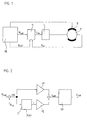
- a numerical control NC which consists of a drive from a controller R, a power unit L and a motor M.
- the numerical control NC supplies a setpoint Nsoll for the Speed of motor M to controller R.
- Controller R sets voltage setpoints Usoll is available for the line part L, which the motor M controlled via pulse width modulation.
- a tachometer monitors the speed of the motor M and provides an actual value Nist of the speed back to controller R. Current sensors, the actual current values, are not shown deliver to the controller.
- a holding brake B is used to determine the Axis and can be operated via the numerical control NC.
- controller R which is shown in more detail in Figure 2, there is a PI controller for the speed and a current regulator SR.
- This system could, for example serve to control a tool spindle.
- the controller would be R to supplement an upstream position controller, which is a position setpoint from the numerical control NC and an actual position value from a position encoder accepts and a speed setpoint Nset to the speed controller emits.
- FIG. 2 shows how the difference ⁇ N between the speed setpoint Nset and actual speed value N is a current setpoint for the current controller SR is generated.
- the difference ⁇ N becomes one proportional gain factor KP multiplied
- the difference ⁇ N is integrated in time in the integrator l and the integral sum i multiplied by an integral gain factor Kl.
- the current regulator SR generates one as mentioned Voltage setpoint Usoll, which is transferred to the power section L.
- the controller R is digital, the necessary adjustments can be made run particularly easily.
- the content of the integrator 1 can be used for a calculation easily read according to the above equation and e.g. in numerical NC control used to calculate the correction value corr become.
- the correction factor Korr can be loaded into the integrator 1 be so that there is no jump at the output of the speed controller.
Landscapes
- Engineering & Computer Science (AREA)
- General Physics & Mathematics (AREA)
- Computer Vision & Pattern Recognition (AREA)
- Evolutionary Computation (AREA)
- Medical Informatics (AREA)
- Software Systems (AREA)
- Artificial Intelligence (AREA)
- Physics & Mathematics (AREA)
- Automation & Control Theory (AREA)
- Health & Medical Sciences (AREA)
- Control Of Position Or Direction (AREA)
- Control Of Multiple Motors (AREA)
- Feedback Control In General (AREA)
- Braking Arrangements (AREA)
- Stopping Of Electric Motors (AREA)
- Control Of Electric Motors In General (AREA)
- Numerical Control (AREA)
Abstract
Description
- Figur 1
- einen numerisch gesteuerten Antrieb mit Haltebremse,
- Figur 2
- einen Regelkreis mit Drehzahlregler und Stromregler
Claims (8)
- Verfahren zum Betätigen einer Haltebremse (B) eines elektrischen Antriebs mit Motor (M) und Regelkreis (R) mit Regelparametern (KP, Kl), bei dem wenigstens einer der Regelparameter (KP, Kl) angepaßt wird, gekennzeichnet durch einen ersten Schritt, nach dem der wenigstens eine Regelparameter (KP, Kl) so angepaßt wird, daß bei eingelegter Haltebremse (B) Oszillationen vermieden oder stark verringert werden und in einem zweiten Schritt die Haltebremse (B) betätigt wird.
- Verfahren nach Anspruch 1, dadurch gekennzeichnet, daß die Anpassung der Regelparameter (KP, Kl) so erfolgt, daß an einem Ausgang des Regelkreises (R) keine Änderung eintritt.
- Verfahren nach Anspruch 1 oder 2, dadurch gekennzeichnet, daß vor der Anpassung der Regelparameter (KP, Kl) zunächst ein ausgeregelter Zustand abgewartet wird.
- Verfahren nach Anspruch 2 oder 3, dadurch gekennzeichnet, daß dem Regelkreis (R) ein Korrekturwert (Korr) zugeführt wird, der eine durch die Anpassung der Regelparameter (KP, Kl) verursachte Änderung am Ausgang des Regelkreises (R) vermeidet.
- Verfahren nach Anspruch 4, dadurch gekennzeichnet, daß der Inhalt (i) des Integrierers (1) des Regelkreises (R) um den Korrekturwert (Korr) so geändert wird, daß sich der Ausgang des Reglers (R) aufgrund angepaßter Regelparameter (KP, Kl) nicht ändert.
- Verfahren nach einem der vorhergehenden Ansprüche, dadurch gekennzeichnet, daß im ersten Schritt ein proportionaler Verstärkungsfaktor (KP) und ein integraler Verstärkungsfaktor (Kl) im Regelkreis (R) vor dem Einlegen der Haltebremse (B) reduziert bzw. nach dem Lösen der Bremse erhöht werden.
- Verfahren nach Anspruch 6, dadurch gekennzeichnet, daß der proportionale Verstärkungsfaktor (KP) und der integrale Verstärkungsfaktor (Kl) in einem Drehzahl- bzw. Geschwindigkeitsregler reduziert werden.
- Numerische Steuerung für eine Werkzeugmaschine mit einem Antrieb bestehend aus einem Regler (R) und einem Motor (M) mit einer Haltebremse (B), eingerichtet zur Durchführung eines Verfahrens nach einem der Ansprüche 1 - 7.
Applications Claiming Priority (2)
| Application Number | Priority Date | Filing Date | Title |
|---|---|---|---|
| DE10229350A DE10229350A1 (de) | 2002-06-29 | 2002-06-29 | Verfahren zum Betätigen einer Haltebremse |
| DE10229350 | 2002-06-29 |
Publications (2)
| Publication Number | Publication Date |
|---|---|
| EP1376277A1 true EP1376277A1 (de) | 2004-01-02 |
| EP1376277B1 EP1376277B1 (de) | 2008-01-16 |
Family
ID=29716738
Family Applications (1)
| Application Number | Title | Priority Date | Filing Date |
|---|---|---|---|
| EP03013531A Expired - Lifetime EP1376277B1 (de) | 2002-06-29 | 2003-06-13 | Verfahren zum Betätigen einer Haltebremse |
Country Status (5)
| Country | Link |
|---|---|
| US (1) | US6970761B2 (de) |
| EP (1) | EP1376277B1 (de) |
| AT (1) | ATE384286T1 (de) |
| DE (2) | DE10229350A1 (de) |
| ES (1) | ES2299645T3 (de) |
Families Citing this family (6)
| Publication number | Priority date | Publication date | Assignee | Title |
|---|---|---|---|---|
| US7180255B2 (en) * | 2005-01-26 | 2007-02-20 | Delphi Technologies, Inc. | Controlling the release of a brush motor which has applied a load |
| TWI274468B (en) * | 2005-05-04 | 2007-02-21 | Sunplus Technology Co Ltd | Brake system and method for a direct current brushed motor without a hall sensor |
| JP5746308B2 (ja) * | 2013-11-26 | 2015-07-08 | ファナック株式会社 | ブレーキ落下量を低減する機能を備えたサーボ制御装置 |
| CN110361965B (zh) * | 2019-05-20 | 2022-01-11 | 北京理工大学 | 线性Luenberger观测器的构建方法 |
| EP4527177A3 (de) | 2021-09-18 | 2025-05-07 | Nanjing Chervon Industry Co., Ltd. | Aufsitzrasenmäher, anzeigeschnittstelle eines elektrowerkzeugs und aufsitzmaschine |
| EP4233169A4 (de) * | 2021-10-15 | 2023-12-13 | Nanjing Chervon Industry Co., Ltd. | Rasenmäher |
Citations (4)
| Publication number | Priority date | Publication date | Assignee | Title |
|---|---|---|---|---|
| US5144213A (en) * | 1988-12-28 | 1992-09-01 | Fanuc Ltd | Brake control method of gravity axis |
| WO1999005578A1 (en) * | 1997-07-22 | 1999-02-04 | Honeywell Inc. | Load-based adaptive gain control |
| JP2000047732A (ja) * | 1998-07-31 | 2000-02-18 | Yaskawa Electric Corp | サーボ制御装置およびサーボ制御方法 |
| US6317637B1 (en) * | 1998-10-22 | 2001-11-13 | National Instruments Corporation | System and method for maintaining output continuity of PID controllers in response to changes in controller parameters |
Family Cites Families (11)
| Publication number | Priority date | Publication date | Assignee | Title |
|---|---|---|---|---|
| US3949582A (en) * | 1975-04-11 | 1976-04-13 | Eaton-Leonard Corporation | Positioning servo and controlled mechanism |
| DE2810646A1 (de) * | 1977-03-18 | 1978-09-21 | Komatsu Mfg Co Ltd | Numerisches steuersystem fuer eine werkzeugmaschine |
| JPS5843220B2 (ja) * | 1978-12-16 | 1983-09-26 | ファナック株式会社 | 主軸定位置停止制御装置 |
| US4485594A (en) * | 1982-09-07 | 1984-12-04 | Brown & Sharpe Manufacturing Company | Surface grinding machine |
| EP0374259B1 (de) * | 1988-04-19 | 1995-10-18 | Nakamura-Tome Precision Ind. Co., Ltd. | Cnc-drehmaschine mit zwei gegenüberliegenden hauptspindeln |
| US5729511A (en) * | 1991-02-15 | 1998-03-17 | Discovision Associates | Optical disc system having servo motor and servo error detection assembly operated relative to monitored quad sum signal |
| JPH05184167A (ja) * | 1992-01-06 | 1993-07-23 | Canon Inc | 進行波型モータの制御装置 |
| US5596931A (en) * | 1992-10-16 | 1997-01-28 | Heidelberger Druckmaschinen Ag | Device and method for damping mechanical vibrations of a printing press |
| EP0801843A1 (de) * | 1994-03-03 | 1997-10-22 | Iomega Corporation | Servo-motor regler mit positionsinterpolation |
| KR970003508B1 (ko) * | 1994-03-25 | 1997-03-18 | 한국원자력연구소 | 크레인의 진동방지를 위한 속도 제어 방법 |
| JPH10218306A (ja) * | 1997-02-06 | 1998-08-18 | Toyota Autom Loom Works Ltd | 自動倉庫を備えた物流システム |
-
2002
- 2002-06-29 DE DE10229350A patent/DE10229350A1/de not_active Withdrawn
-
2003
- 2003-06-13 EP EP03013531A patent/EP1376277B1/de not_active Expired - Lifetime
- 2003-06-13 DE DE50309007T patent/DE50309007D1/de not_active Expired - Lifetime
- 2003-06-13 AT AT03013531T patent/ATE384286T1/de not_active IP Right Cessation
- 2003-06-13 ES ES03013531T patent/ES2299645T3/es not_active Expired - Lifetime
- 2003-06-16 US US10/463,053 patent/US6970761B2/en not_active Expired - Lifetime
Patent Citations (4)
| Publication number | Priority date | Publication date | Assignee | Title |
|---|---|---|---|---|
| US5144213A (en) * | 1988-12-28 | 1992-09-01 | Fanuc Ltd | Brake control method of gravity axis |
| WO1999005578A1 (en) * | 1997-07-22 | 1999-02-04 | Honeywell Inc. | Load-based adaptive gain control |
| JP2000047732A (ja) * | 1998-07-31 | 2000-02-18 | Yaskawa Electric Corp | サーボ制御装置およびサーボ制御方法 |
| US6317637B1 (en) * | 1998-10-22 | 2001-11-13 | National Instruments Corporation | System and method for maintaining output continuity of PID controllers in response to changes in controller parameters |
Also Published As
| Publication number | Publication date |
|---|---|
| ES2299645T3 (es) | 2008-06-01 |
| DE50309007D1 (de) | 2008-03-06 |
| DE10229350A1 (de) | 2004-01-15 |
| EP1376277B1 (de) | 2008-01-16 |
| ATE384286T1 (de) | 2008-02-15 |
| US20040002775A1 (en) | 2004-01-01 |
| US6970761B2 (en) | 2005-11-29 |
Similar Documents
| Publication | Publication Date | Title |
|---|---|---|
| EP2829365B1 (de) | Verfahren und Vorrichtung zum Bremsen einer Roboterachsanordnung | |
| DE102010012424B4 (de) | Servo-Steuergerät mit zweifacher Stellungsrückkopplung | |
| DE102014000138B4 (de) | Motorsteuervorrichtung zum Kompensieren von Spiel | |
| EP2579112B1 (de) | Regeleinrichtung | |
| DE102017205206A1 (de) | Verfahren zum Betreiben einer Steuervorrichtung für eine Bremsanlage eines Kraftfahrzeugs sowie Steuervorrichtung und Kraftfahrzeug | |
| EP2485227A1 (de) | Verfahren zur Steuerung eines Prozesses zum Wickeln eines azentrischen Spulenkörpers und nach dem Verfahren arbeitende Vorrichtung | |
| AT522167B1 (de) | Verfahren und Vorrichtung zur vorausschauenden Fahrzeugkontrolle | |
| EP3383781A1 (de) | Verfahren zur ansteuerung einer bremseinrichtung einer aufzugsanlage | |
| EP3983777B1 (de) | Verfahren und kontrollvorrichtung zum kontrollieren eines fahrzeugs | |
| DE102010029937A1 (de) | Verfahren und Vorrichtung zum Reduzieren von Schwingungen auf einer Abtriebswelle eines Antriebsmotors | |
| EP1916416A2 (de) | Verfahren zum Betreiben einer Windenergieanlage | |
| EP0896263A2 (de) | Verfahren und Schaltungsanordnung zur Ermittlung optimaler Reglerparameter für eine Drehzahlregelung | |
| EP1376277B1 (de) | Verfahren zum Betätigen einer Haltebremse | |
| EP3592991B1 (de) | Verfahren zum ansteuern eines hydraulischen stellantriebes, steuereinrichtung und stellantriebsteuerung | |
| DE19726872C2 (de) | Verfahren zum Steuern einer umlaufenden Rollenschere | |
| EP3245730A1 (de) | Antriebsvorrichtung mit trägheitsmomentschätzung | |
| EP1818744B1 (de) | Reglerstruktur mit einem Torsionsmodell | |
| EP1005147B1 (de) | Verfahren und Schaltungsanordnung zur Ermittlung einer optimalen Verstärkung des Integrators eines Drehzahlreglers | |
| AT514232B1 (de) | Verfahren zum Steuern oder Regeln einer Spritzgießmaschine | |
| WO2017140455A1 (de) | Drehzahlabhängige kompensation von lagefehlern | |
| DE102011121839A1 (de) | Verfahren zur Bewegungssteuerung mit Trägheitsmoment - Ermittlung | |
| EP0791193A1 (de) | Satzübergreifende geschwindigkeitsführung für beliebigen override-bereich | |
| EP2736832B1 (de) | Verfahren zum steuern der längsbewegung eines schienengebundenen fahrzeugs, kurvenfahrtsteuerungsvorrichtung und schienengebundenes fahrzeug | |
| DE102016006213A1 (de) | Verfahren zur Durchführung eines automatischen Fahrmanövers eines Fahrzeugs und Fahrzeug | |
| EP2179497B1 (de) | Anlage und Verfahren zur Lageregelung von zumindest zwei Antrieben |
Legal Events
| Date | Code | Title | Description |
|---|---|---|---|
| PUAI | Public reference made under article 153(3) epc to a published international application that has entered the european phase |
Free format text: ORIGINAL CODE: 0009012 |
|
| AK | Designated contracting states |
Kind code of ref document: A1 Designated state(s): AT BE BG CH CY CZ DE DK EE ES FI FR GB GR HU IE IT LI LU MC NL PT RO SE SI SK TR |
|
| AX | Request for extension of the european patent |
Extension state: AL LT LV MK |
|
| 17P | Request for examination filed |
Effective date: 20040702 |
|
| AKX | Designation fees paid |
Designated state(s): AT BE BG CH CY CZ DE DK EE ES FI FR GB GR HU IE IT LI LU MC NL PT RO SE SI SK TR |
|
| 17Q | First examination report despatched |
Effective date: 20060102 |
|
| GRAP | Despatch of communication of intention to grant a patent |
Free format text: ORIGINAL CODE: EPIDOSNIGR1 |
|
| GRAS | Grant fee paid |
Free format text: ORIGINAL CODE: EPIDOSNIGR3 |
|
| GRAA | (expected) grant |
Free format text: ORIGINAL CODE: 0009210 |
|
| AK | Designated contracting states |
Kind code of ref document: B1 Designated state(s): AT BE BG CH CY CZ DE DK EE ES FI FR GB GR HU IE IT LI LU MC NL PT RO SE SI SK TR |
|
| REG | Reference to a national code |
Ref country code: GB Ref legal event code: FG4D Free format text: NOT ENGLISH |
|
| REG | Reference to a national code |
Ref country code: CH Ref legal event code: EP |
|
| REG | Reference to a national code |
Ref country code: IE Ref legal event code: FG4D Free format text: LANGUAGE OF EP DOCUMENT: GERMAN |
|
| GBT | Gb: translation of ep patent filed (gb section 77(6)(a)/1977) |
Effective date: 20080207 |
|
| REF | Corresponds to: |
Ref document number: 50309007 Country of ref document: DE Date of ref document: 20080306 Kind code of ref document: P |
|
| PG25 | Lapsed in a contracting state [announced via postgrant information from national office to epo] |
Ref country code: NL Free format text: LAPSE BECAUSE OF FAILURE TO SUBMIT A TRANSLATION OF THE DESCRIPTION OR TO PAY THE FEE WITHIN THE PRESCRIBED TIME-LIMIT Effective date: 20080116 |
|
| REG | Reference to a national code |
Ref country code: ES Ref legal event code: FG2A Ref document number: 2299645 Country of ref document: ES Kind code of ref document: T3 |
|
| NLV1 | Nl: lapsed or annulled due to failure to fulfill the requirements of art. 29p and 29m of the patents act | ||
| PG25 | Lapsed in a contracting state [announced via postgrant information from national office to epo] |
Ref country code: FI Free format text: LAPSE BECAUSE OF FAILURE TO SUBMIT A TRANSLATION OF THE DESCRIPTION OR TO PAY THE FEE WITHIN THE PRESCRIBED TIME-LIMIT Effective date: 20080116 |
|
| ET | Fr: translation filed | ||
| PG25 | Lapsed in a contracting state [announced via postgrant information from national office to epo] |
Ref country code: BG Free format text: LAPSE BECAUSE OF FAILURE TO SUBMIT A TRANSLATION OF THE DESCRIPTION OR TO PAY THE FEE WITHIN THE PRESCRIBED TIME-LIMIT Effective date: 20080416 |
|
| PG25 | Lapsed in a contracting state [announced via postgrant information from national office to epo] |
Ref country code: PT Free format text: LAPSE BECAUSE OF FAILURE TO SUBMIT A TRANSLATION OF THE DESCRIPTION OR TO PAY THE FEE WITHIN THE PRESCRIBED TIME-LIMIT Effective date: 20080616 Ref country code: SI Free format text: LAPSE BECAUSE OF FAILURE TO SUBMIT A TRANSLATION OF THE DESCRIPTION OR TO PAY THE FEE WITHIN THE PRESCRIBED TIME-LIMIT Effective date: 20080116 |
|
| REG | Reference to a national code |
Ref country code: IE Ref legal event code: FD4D |
|
| PG25 | Lapsed in a contracting state [announced via postgrant information from national office to epo] |
Ref country code: SE Free format text: LAPSE BECAUSE OF FAILURE TO SUBMIT A TRANSLATION OF THE DESCRIPTION OR TO PAY THE FEE WITHIN THE PRESCRIBED TIME-LIMIT Effective date: 20080416 Ref country code: IE Free format text: LAPSE BECAUSE OF FAILURE TO SUBMIT A TRANSLATION OF THE DESCRIPTION OR TO PAY THE FEE WITHIN THE PRESCRIBED TIME-LIMIT Effective date: 20080116 Ref country code: DK Free format text: LAPSE BECAUSE OF FAILURE TO SUBMIT A TRANSLATION OF THE DESCRIPTION OR TO PAY THE FEE WITHIN THE PRESCRIBED TIME-LIMIT Effective date: 20080116 Ref country code: CZ Free format text: LAPSE BECAUSE OF FAILURE TO SUBMIT A TRANSLATION OF THE DESCRIPTION OR TO PAY THE FEE WITHIN THE PRESCRIBED TIME-LIMIT Effective date: 20080116 Ref country code: SK Free format text: LAPSE BECAUSE OF FAILURE TO SUBMIT A TRANSLATION OF THE DESCRIPTION OR TO PAY THE FEE WITHIN THE PRESCRIBED TIME-LIMIT Effective date: 20080116 |
|
| PLBE | No opposition filed within time limit |
Free format text: ORIGINAL CODE: 0009261 |
|
| STAA | Information on the status of an ep patent application or granted ep patent |
Free format text: STATUS: NO OPPOSITION FILED WITHIN TIME LIMIT |
|
| PG25 | Lapsed in a contracting state [announced via postgrant information from national office to epo] |
Ref country code: RO Free format text: LAPSE BECAUSE OF FAILURE TO SUBMIT A TRANSLATION OF THE DESCRIPTION OR TO PAY THE FEE WITHIN THE PRESCRIBED TIME-LIMIT Effective date: 20080116 |
|
| 26N | No opposition filed |
Effective date: 20081017 |
|
| BERE | Be: lapsed |
Owner name: DR. JOHANNES HEIDENHAIN G.M.B.H. Effective date: 20080630 |
|
| PG25 | Lapsed in a contracting state [announced via postgrant information from national office to epo] |
Ref country code: MC Free format text: LAPSE BECAUSE OF NON-PAYMENT OF DUE FEES Effective date: 20080630 |
|
| REG | Reference to a national code |
Ref country code: CH Ref legal event code: PL |
|
| PG25 | Lapsed in a contracting state [announced via postgrant information from national office to epo] |
Ref country code: BE Free format text: LAPSE BECAUSE OF NON-PAYMENT OF DUE FEES Effective date: 20080630 |
|
| PG25 | Lapsed in a contracting state [announced via postgrant information from national office to epo] |
Ref country code: EE Free format text: LAPSE BECAUSE OF FAILURE TO SUBMIT A TRANSLATION OF THE DESCRIPTION OR TO PAY THE FEE WITHIN THE PRESCRIBED TIME-LIMIT Effective date: 20080116 |
|
| PG25 | Lapsed in a contracting state [announced via postgrant information from national office to epo] |
Ref country code: LI Free format text: LAPSE BECAUSE OF NON-PAYMENT OF DUE FEES Effective date: 20080630 Ref country code: CH Free format text: LAPSE BECAUSE OF NON-PAYMENT OF DUE FEES Effective date: 20080630 |
|
| PG25 | Lapsed in a contracting state [announced via postgrant information from national office to epo] |
Ref country code: CY Free format text: LAPSE BECAUSE OF FAILURE TO SUBMIT A TRANSLATION OF THE DESCRIPTION OR TO PAY THE FEE WITHIN THE PRESCRIBED TIME-LIMIT Effective date: 20080116 |
|
| PG25 | Lapsed in a contracting state [announced via postgrant information from national office to epo] |
Ref country code: AT Free format text: LAPSE BECAUSE OF NON-PAYMENT OF DUE FEES Effective date: 20080613 |
|
| PG25 | Lapsed in a contracting state [announced via postgrant information from national office to epo] |
Ref country code: LU Free format text: LAPSE BECAUSE OF NON-PAYMENT OF DUE FEES Effective date: 20080613 Ref country code: HU Free format text: LAPSE BECAUSE OF FAILURE TO SUBMIT A TRANSLATION OF THE DESCRIPTION OR TO PAY THE FEE WITHIN THE PRESCRIBED TIME-LIMIT Effective date: 20080717 |
|
| PG25 | Lapsed in a contracting state [announced via postgrant information from national office to epo] |
Ref country code: TR Free format text: LAPSE BECAUSE OF FAILURE TO SUBMIT A TRANSLATION OF THE DESCRIPTION OR TO PAY THE FEE WITHIN THE PRESCRIBED TIME-LIMIT Effective date: 20080116 |
|
| PG25 | Lapsed in a contracting state [announced via postgrant information from national office to epo] |
Ref country code: GR Free format text: LAPSE BECAUSE OF FAILURE TO SUBMIT A TRANSLATION OF THE DESCRIPTION OR TO PAY THE FEE WITHIN THE PRESCRIBED TIME-LIMIT Effective date: 20080417 |
|
| REG | Reference to a national code |
Ref country code: FR Ref legal event code: PLFP Year of fee payment: 14 |
|
| REG | Reference to a national code |
Ref country code: FR Ref legal event code: PLFP Year of fee payment: 15 |
|
| PGFP | Annual fee paid to national office [announced via postgrant information from national office to epo] |
Ref country code: GB Payment date: 20170620 Year of fee payment: 15 Ref country code: FR Payment date: 20170621 Year of fee payment: 15 |
|
| PGFP | Annual fee paid to national office [announced via postgrant information from national office to epo] |
Ref country code: ES Payment date: 20180723 Year of fee payment: 16 Ref country code: IT Payment date: 20180627 Year of fee payment: 16 |
|
| GBPC | Gb: european patent ceased through non-payment of renewal fee |
Effective date: 20180613 |
|
| PG25 | Lapsed in a contracting state [announced via postgrant information from national office to epo] |
Ref country code: FR Free format text: LAPSE BECAUSE OF NON-PAYMENT OF DUE FEES Effective date: 20180630 Ref country code: GB Free format text: LAPSE BECAUSE OF NON-PAYMENT OF DUE FEES Effective date: 20180613 |
|
| PGFP | Annual fee paid to national office [announced via postgrant information from national office to epo] |
Ref country code: DE Payment date: 20190619 Year of fee payment: 17 |
|
| PG25 | Lapsed in a contracting state [announced via postgrant information from national office to epo] |
Ref country code: IT Free format text: LAPSE BECAUSE OF NON-PAYMENT OF DUE FEES Effective date: 20190613 |
|
| REG | Reference to a national code |
Ref country code: ES Ref legal event code: FD2A Effective date: 20201028 |
|
| REG | Reference to a national code |
Ref country code: DE Ref legal event code: R119 Ref document number: 50309007 Country of ref document: DE |
|
| PG25 | Lapsed in a contracting state [announced via postgrant information from national office to epo] |
Ref country code: ES Free format text: LAPSE BECAUSE OF NON-PAYMENT OF DUE FEES Effective date: 20190614 |
|
| PG25 | Lapsed in a contracting state [announced via postgrant information from national office to epo] |
Ref country code: DE Free format text: LAPSE BECAUSE OF NON-PAYMENT OF DUE FEES Effective date: 20210101 |