EP1376083A2 - Schweissindikator für ein Schweissfitting - Google Patents
Schweissindikator für ein Schweissfitting Download PDFInfo
- Publication number
- EP1376083A2 EP1376083A2 EP20030014257 EP03014257A EP1376083A2 EP 1376083 A2 EP1376083 A2 EP 1376083A2 EP 20030014257 EP20030014257 EP 20030014257 EP 03014257 A EP03014257 A EP 03014257A EP 1376083 A2 EP1376083 A2 EP 1376083A2
- Authority
- EP
- European Patent Office
- Prior art keywords
- welding
- recess
- sleeve
- fitting body
- additional material
- Prior art date
- Legal status (The legal status is an assumption and is not a legal conclusion. Google has not performed a legal analysis and makes no representation as to the accuracy of the status listed.)
- Granted
Links
- 238000003466 welding Methods 0.000 title claims description 89
- 230000004927 fusion Effects 0.000 title 1
- 239000000463 material Substances 0.000 claims abstract description 75
- 238000010438 heat treatment Methods 0.000 claims abstract description 22
- 239000004033 plastic Substances 0.000 claims abstract description 14
- 230000008859 change Effects 0.000 claims abstract description 13
- 238000007789 sealing Methods 0.000 claims description 13
- 238000005192 partition Methods 0.000 claims description 6
- 238000002844 melting Methods 0.000 claims description 5
- 230000008018 melting Effects 0.000 claims description 5
- 238000011038 discontinuous diafiltration by volume reduction Methods 0.000 claims description 4
- 238000009434 installation Methods 0.000 claims 1
- 230000008961 swelling Effects 0.000 description 18
- 239000003795 chemical substances by application Substances 0.000 description 15
- 239000000155 melt Substances 0.000 description 6
- 239000004020 conductor Substances 0.000 description 4
- 210000004243 sweat Anatomy 0.000 description 4
- 229910052751 metal Inorganic materials 0.000 description 3
- 239000002184 metal Substances 0.000 description 3
- 230000003287 optical effect Effects 0.000 description 3
- 239000001993 wax Substances 0.000 description 3
- 229910001369 Brass Inorganic materials 0.000 description 2
- RYGMFSIKBFXOCR-UHFFFAOYSA-N Copper Chemical compound [Cu] RYGMFSIKBFXOCR-UHFFFAOYSA-N 0.000 description 2
- 229910052782 aluminium Inorganic materials 0.000 description 2
- XAGFODPZIPBFFR-UHFFFAOYSA-N aluminium Chemical compound [Al] XAGFODPZIPBFFR-UHFFFAOYSA-N 0.000 description 2
- 230000015572 biosynthetic process Effects 0.000 description 2
- 239000010951 brass Substances 0.000 description 2
- 229910052802 copper Inorganic materials 0.000 description 2
- 239000010949 copper Substances 0.000 description 2
- 230000000694 effects Effects 0.000 description 2
- 230000002787 reinforcement Effects 0.000 description 2
- 238000010079 rubber tapping Methods 0.000 description 2
- 230000000007 visual effect Effects 0.000 description 2
- TVEXGJYMHHTVKP-UHFFFAOYSA-N 6-oxabicyclo[3.2.1]oct-3-en-7-one Chemical compound C1C2C(=O)OC1C=CC2 TVEXGJYMHHTVKP-UHFFFAOYSA-N 0.000 description 1
- 229920000049 Carbon (fiber) Polymers 0.000 description 1
- 230000009471 action Effects 0.000 description 1
- 238000004873 anchoring Methods 0.000 description 1
- 239000004917 carbon fiber Substances 0.000 description 1
- 239000011248 coating agent Substances 0.000 description 1
- 238000000576 coating method Methods 0.000 description 1
- 239000003086 colorant Substances 0.000 description 1
- 238000001816 cooling Methods 0.000 description 1
- 238000011161 development Methods 0.000 description 1
- 230000018109 developmental process Effects 0.000 description 1
- 238000005553 drilling Methods 0.000 description 1
- 238000001035 drying Methods 0.000 description 1
- 238000005516 engineering process Methods 0.000 description 1
- 239000006261 foam material Substances 0.000 description 1
- 238000005187 foaming Methods 0.000 description 1
- 239000008187 granular material Substances 0.000 description 1
- 230000006698 induction Effects 0.000 description 1
- 230000010354 integration Effects 0.000 description 1
- 239000007788 liquid Substances 0.000 description 1
- 238000004519 manufacturing process Methods 0.000 description 1
- 230000007246 mechanism Effects 0.000 description 1
- 229920000642 polymer Polymers 0.000 description 1
- 239000000843 powder Substances 0.000 description 1
- 238000003825 pressing Methods 0.000 description 1
- 230000009467 reduction Effects 0.000 description 1
- 230000003716 rejuvenation Effects 0.000 description 1
- 230000004044 response Effects 0.000 description 1
- 239000007787 solid Substances 0.000 description 1
- 239000002195 soluble material Substances 0.000 description 1
- 239000011800 void material Substances 0.000 description 1
Images




Classifications
-
- B—PERFORMING OPERATIONS; TRANSPORTING
- B29—WORKING OF PLASTICS; WORKING OF SUBSTANCES IN A PLASTIC STATE IN GENERAL
- B29C—SHAPING OR JOINING OF PLASTICS; SHAPING OF MATERIAL IN A PLASTIC STATE, NOT OTHERWISE PROVIDED FOR; AFTER-TREATMENT OF THE SHAPED PRODUCTS, e.g. REPAIRING
- B29C66/00—General aspects of processes or apparatus for joining preformed parts
- B29C66/90—Measuring or controlling the joining process
- B29C66/91—Measuring or controlling the joining process by measuring or controlling the temperature, the heat or the thermal flux
- B29C66/912—Measuring or controlling the joining process by measuring or controlling the temperature, the heat or the thermal flux by measuring the temperature, the heat or the thermal flux
- B29C66/9121—Measuring or controlling the joining process by measuring or controlling the temperature, the heat or the thermal flux by measuring the temperature, the heat or the thermal flux by measuring the temperature
- B29C66/91211—Measuring or controlling the joining process by measuring or controlling the temperature, the heat or the thermal flux by measuring the temperature, the heat or the thermal flux by measuring the temperature with special temperature measurement means or methods
- B29C66/91218—Measuring or controlling the joining process by measuring or controlling the temperature, the heat or the thermal flux by measuring the temperature, the heat or the thermal flux by measuring the temperature with special temperature measurement means or methods using colour change, e.g. using separate colour indicators
-
- B—PERFORMING OPERATIONS; TRANSPORTING
- B29—WORKING OF PLASTICS; WORKING OF SUBSTANCES IN A PLASTIC STATE IN GENERAL
- B29C—SHAPING OR JOINING OF PLASTICS; SHAPING OF MATERIAL IN A PLASTIC STATE, NOT OTHERWISE PROVIDED FOR; AFTER-TREATMENT OF THE SHAPED PRODUCTS, e.g. REPAIRING
- B29C65/00—Joining or sealing of preformed parts, e.g. welding of plastics materials; Apparatus therefor
- B29C65/02—Joining or sealing of preformed parts, e.g. welding of plastics materials; Apparatus therefor by heating, with or without pressure
- B29C65/34—Joining or sealing of preformed parts, e.g. welding of plastics materials; Apparatus therefor by heating, with or without pressure using heated elements which remain in the joint, e.g. "verlorenes Schweisselement"
- B29C65/3404—Joining or sealing of preformed parts, e.g. welding of plastics materials; Apparatus therefor by heating, with or without pressure using heated elements which remain in the joint, e.g. "verlorenes Schweisselement" characterised by the type of heated elements which remain in the joint
- B29C65/342—Joining or sealing of preformed parts, e.g. welding of plastics materials; Apparatus therefor by heating, with or without pressure using heated elements which remain in the joint, e.g. "verlorenes Schweisselement" characterised by the type of heated elements which remain in the joint comprising at least a single wire, e.g. in the form of a winding
-
- B—PERFORMING OPERATIONS; TRANSPORTING
- B29—WORKING OF PLASTICS; WORKING OF SUBSTANCES IN A PLASTIC STATE IN GENERAL
- B29C—SHAPING OR JOINING OF PLASTICS; SHAPING OF MATERIAL IN A PLASTIC STATE, NOT OTHERWISE PROVIDED FOR; AFTER-TREATMENT OF THE SHAPED PRODUCTS, e.g. REPAIRING
- B29C66/00—General aspects of processes or apparatus for joining preformed parts
- B29C66/50—General aspects of joining tubular articles; General aspects of joining long products, i.e. bars or profiled elements; General aspects of joining single elements to tubular articles, hollow articles or bars; General aspects of joining several hollow-preforms to form hollow or tubular articles
- B29C66/51—Joining tubular articles, profiled elements or bars; Joining single elements to tubular articles, hollow articles or bars; Joining several hollow-preforms to form hollow or tubular articles
- B29C66/52—Joining tubular articles, bars or profiled elements
- B29C66/522—Joining tubular articles
-
- B—PERFORMING OPERATIONS; TRANSPORTING
- B29—WORKING OF PLASTICS; WORKING OF SUBSTANCES IN A PLASTIC STATE IN GENERAL
- B29C—SHAPING OR JOINING OF PLASTICS; SHAPING OF MATERIAL IN A PLASTIC STATE, NOT OTHERWISE PROVIDED FOR; AFTER-TREATMENT OF THE SHAPED PRODUCTS, e.g. REPAIRING
- B29C66/00—General aspects of processes or apparatus for joining preformed parts
- B29C66/50—General aspects of joining tubular articles; General aspects of joining long products, i.e. bars or profiled elements; General aspects of joining single elements to tubular articles, hollow articles or bars; General aspects of joining several hollow-preforms to form hollow or tubular articles
- B29C66/51—Joining tubular articles, profiled elements or bars; Joining single elements to tubular articles, hollow articles or bars; Joining several hollow-preforms to form hollow or tubular articles
- B29C66/52—Joining tubular articles, bars or profiled elements
- B29C66/522—Joining tubular articles
- B29C66/5229—Joining tubular articles involving the use of a socket
-
- B—PERFORMING OPERATIONS; TRANSPORTING
- B29—WORKING OF PLASTICS; WORKING OF SUBSTANCES IN A PLASTIC STATE IN GENERAL
- B29C—SHAPING OR JOINING OF PLASTICS; SHAPING OF MATERIAL IN A PLASTIC STATE, NOT OTHERWISE PROVIDED FOR; AFTER-TREATMENT OF THE SHAPED PRODUCTS, e.g. REPAIRING
- B29C66/00—General aspects of processes or apparatus for joining preformed parts
- B29C66/50—General aspects of joining tubular articles; General aspects of joining long products, i.e. bars or profiled elements; General aspects of joining single elements to tubular articles, hollow articles or bars; General aspects of joining several hollow-preforms to form hollow or tubular articles
- B29C66/51—Joining tubular articles, profiled elements or bars; Joining single elements to tubular articles, hollow articles or bars; Joining several hollow-preforms to form hollow or tubular articles
- B29C66/52—Joining tubular articles, bars or profiled elements
- B29C66/522—Joining tubular articles
- B29C66/5229—Joining tubular articles involving the use of a socket
- B29C66/52295—Joining tubular articles involving the use of a socket said socket comprising reinforcements
-
- B—PERFORMING OPERATIONS; TRANSPORTING
- B29—WORKING OF PLASTICS; WORKING OF SUBSTANCES IN A PLASTIC STATE IN GENERAL
- B29C—SHAPING OR JOINING OF PLASTICS; SHAPING OF MATERIAL IN A PLASTIC STATE, NOT OTHERWISE PROVIDED FOR; AFTER-TREATMENT OF THE SHAPED PRODUCTS, e.g. REPAIRING
- B29C66/00—General aspects of processes or apparatus for joining preformed parts
- B29C66/90—Measuring or controlling the joining process
- B29C66/91—Measuring or controlling the joining process by measuring or controlling the temperature, the heat or the thermal flux
- B29C66/912—Measuring or controlling the joining process by measuring or controlling the temperature, the heat or the thermal flux by measuring the temperature, the heat or the thermal flux
- B29C66/9121—Measuring or controlling the joining process by measuring or controlling the temperature, the heat or the thermal flux by measuring the temperature, the heat or the thermal flux by measuring the temperature
- B29C66/91211—Measuring or controlling the joining process by measuring or controlling the temperature, the heat or the thermal flux by measuring the temperature, the heat or the thermal flux by measuring the temperature with special temperature measurement means or methods
-
- B—PERFORMING OPERATIONS; TRANSPORTING
- B29—WORKING OF PLASTICS; WORKING OF SUBSTANCES IN A PLASTIC STATE IN GENERAL
- B29C—SHAPING OR JOINING OF PLASTICS; SHAPING OF MATERIAL IN A PLASTIC STATE, NOT OTHERWISE PROVIDED FOR; AFTER-TREATMENT OF THE SHAPED PRODUCTS, e.g. REPAIRING
- B29C66/00—General aspects of processes or apparatus for joining preformed parts
- B29C66/90—Measuring or controlling the joining process
- B29C66/91—Measuring or controlling the joining process by measuring or controlling the temperature, the heat or the thermal flux
- B29C66/912—Measuring or controlling the joining process by measuring or controlling the temperature, the heat or the thermal flux by measuring the temperature, the heat or the thermal flux
- B29C66/9121—Measuring or controlling the joining process by measuring or controlling the temperature, the heat or the thermal flux by measuring the temperature, the heat or the thermal flux by measuring the temperature
- B29C66/91221—Measuring or controlling the joining process by measuring or controlling the temperature, the heat or the thermal flux by measuring the temperature, the heat or the thermal flux by measuring the temperature of the parts to be joined
-
- B—PERFORMING OPERATIONS; TRANSPORTING
- B29—WORKING OF PLASTICS; WORKING OF SUBSTANCES IN A PLASTIC STATE IN GENERAL
- B29C—SHAPING OR JOINING OF PLASTICS; SHAPING OF MATERIAL IN A PLASTIC STATE, NOT OTHERWISE PROVIDED FOR; AFTER-TREATMENT OF THE SHAPED PRODUCTS, e.g. REPAIRING
- B29C66/00—General aspects of processes or apparatus for joining preformed parts
- B29C66/90—Measuring or controlling the joining process
- B29C66/97—Checking completion of joining or correct joining by using indications on at least one of the joined parts
-
- B—PERFORMING OPERATIONS; TRANSPORTING
- B29—WORKING OF PLASTICS; WORKING OF SUBSTANCES IN A PLASTIC STATE IN GENERAL
- B29C—SHAPING OR JOINING OF PLASTICS; SHAPING OF MATERIAL IN A PLASTIC STATE, NOT OTHERWISE PROVIDED FOR; AFTER-TREATMENT OF THE SHAPED PRODUCTS, e.g. REPAIRING
- B29C66/00—General aspects of processes or apparatus for joining preformed parts
- B29C66/90—Measuring or controlling the joining process
- B29C66/97—Checking completion of joining or correct joining by using indications on at least one of the joined parts
- B29C66/972—Checking completion of joining or correct joining by using indications on at least one of the joined parts by extrusion of molten material
-
- B—PERFORMING OPERATIONS; TRANSPORTING
- B29—WORKING OF PLASTICS; WORKING OF SUBSTANCES IN A PLASTIC STATE IN GENERAL
- B29C—SHAPING OR JOINING OF PLASTICS; SHAPING OF MATERIAL IN A PLASTIC STATE, NOT OTHERWISE PROVIDED FOR; AFTER-TREATMENT OF THE SHAPED PRODUCTS, e.g. REPAIRING
- B29C66/00—General aspects of processes or apparatus for joining preformed parts
- B29C66/90—Measuring or controlling the joining process
- B29C66/97—Checking completion of joining or correct joining by using indications on at least one of the joined parts
- B29C66/976—Checking completion of joining or correct joining by using indications on at least one of the joined parts by the use of an indicator pin, e.g. being integral with one of the parts to be joined
-
- G—PHYSICS
- G01—MEASURING; TESTING
- G01K—MEASURING TEMPERATURE; MEASURING QUANTITY OF HEAT; THERMALLY-SENSITIVE ELEMENTS NOT OTHERWISE PROVIDED FOR
- G01K11/00—Measuring temperature based upon physical or chemical changes not covered by groups G01K3/00, G01K5/00, G01K7/00 or G01K9/00
- G01K11/06—Measuring temperature based upon physical or chemical changes not covered by groups G01K3/00, G01K5/00, G01K7/00 or G01K9/00 using melting, freezing, or softening
-
- B—PERFORMING OPERATIONS; TRANSPORTING
- B29—WORKING OF PLASTICS; WORKING OF SUBSTANCES IN A PLASTIC STATE IN GENERAL
- B29C—SHAPING OR JOINING OF PLASTICS; SHAPING OF MATERIAL IN A PLASTIC STATE, NOT OTHERWISE PROVIDED FOR; AFTER-TREATMENT OF THE SHAPED PRODUCTS, e.g. REPAIRING
- B29C65/00—Joining or sealing of preformed parts, e.g. welding of plastics materials; Apparatus therefor
- B29C65/02—Joining or sealing of preformed parts, e.g. welding of plastics materials; Apparatus therefor by heating, with or without pressure
- B29C65/34—Joining or sealing of preformed parts, e.g. welding of plastics materials; Apparatus therefor by heating, with or without pressure using heated elements which remain in the joint, e.g. "verlorenes Schweisselement"
- B29C65/3472—Joining or sealing of preformed parts, e.g. welding of plastics materials; Apparatus therefor by heating, with or without pressure using heated elements which remain in the joint, e.g. "verlorenes Schweisselement" characterised by the composition of the heated elements which remain in the joint
- B29C65/3476—Joining or sealing of preformed parts, e.g. welding of plastics materials; Apparatus therefor by heating, with or without pressure using heated elements which remain in the joint, e.g. "verlorenes Schweisselement" characterised by the composition of the heated elements which remain in the joint being metallic
-
- B—PERFORMING OPERATIONS; TRANSPORTING
- B29—WORKING OF PLASTICS; WORKING OF SUBSTANCES IN A PLASTIC STATE IN GENERAL
- B29C—SHAPING OR JOINING OF PLASTICS; SHAPING OF MATERIAL IN A PLASTIC STATE, NOT OTHERWISE PROVIDED FOR; AFTER-TREATMENT OF THE SHAPED PRODUCTS, e.g. REPAIRING
- B29C65/00—Joining or sealing of preformed parts, e.g. welding of plastics materials; Apparatus therefor
- B29C65/02—Joining or sealing of preformed parts, e.g. welding of plastics materials; Apparatus therefor by heating, with or without pressure
- B29C65/34—Joining or sealing of preformed parts, e.g. welding of plastics materials; Apparatus therefor by heating, with or without pressure using heated elements which remain in the joint, e.g. "verlorenes Schweisselement"
- B29C65/3472—Joining or sealing of preformed parts, e.g. welding of plastics materials; Apparatus therefor by heating, with or without pressure using heated elements which remain in the joint, e.g. "verlorenes Schweisselement" characterised by the composition of the heated elements which remain in the joint
- B29C65/3484—Joining or sealing of preformed parts, e.g. welding of plastics materials; Apparatus therefor by heating, with or without pressure using heated elements which remain in the joint, e.g. "verlorenes Schweisselement" characterised by the composition of the heated elements which remain in the joint being non-metallic
- B29C65/3492—Joining or sealing of preformed parts, e.g. welding of plastics materials; Apparatus therefor by heating, with or without pressure using heated elements which remain in the joint, e.g. "verlorenes Schweisselement" characterised by the composition of the heated elements which remain in the joint being non-metallic being carbon
-
- B—PERFORMING OPERATIONS; TRANSPORTING
- B29—WORKING OF PLASTICS; WORKING OF SUBSTANCES IN A PLASTIC STATE IN GENERAL
- B29C—SHAPING OR JOINING OF PLASTICS; SHAPING OF MATERIAL IN A PLASTIC STATE, NOT OTHERWISE PROVIDED FOR; AFTER-TREATMENT OF THE SHAPED PRODUCTS, e.g. REPAIRING
- B29C65/00—Joining or sealing of preformed parts, e.g. welding of plastics materials; Apparatus therefor
- B29C65/02—Joining or sealing of preformed parts, e.g. welding of plastics materials; Apparatus therefor by heating, with or without pressure
- B29C65/34—Joining or sealing of preformed parts, e.g. welding of plastics materials; Apparatus therefor by heating, with or without pressure using heated elements which remain in the joint, e.g. "verlorenes Schweisselement"
- B29C65/36—Joining or sealing of preformed parts, e.g. welding of plastics materials; Apparatus therefor by heating, with or without pressure using heated elements which remain in the joint, e.g. "verlorenes Schweisselement" heated by induction
- B29C65/3604—Joining or sealing of preformed parts, e.g. welding of plastics materials; Apparatus therefor by heating, with or without pressure using heated elements which remain in the joint, e.g. "verlorenes Schweisselement" heated by induction characterised by the type of elements heated by induction which remain in the joint
- B29C65/362—Joining or sealing of preformed parts, e.g. welding of plastics materials; Apparatus therefor by heating, with or without pressure using heated elements which remain in the joint, e.g. "verlorenes Schweisselement" heated by induction characterised by the type of elements heated by induction which remain in the joint comprising at least a single wire, e.g. in the form of a winding
-
- B—PERFORMING OPERATIONS; TRANSPORTING
- B29—WORKING OF PLASTICS; WORKING OF SUBSTANCES IN A PLASTIC STATE IN GENERAL
- B29C—SHAPING OR JOINING OF PLASTICS; SHAPING OF MATERIAL IN A PLASTIC STATE, NOT OTHERWISE PROVIDED FOR; AFTER-TREATMENT OF THE SHAPED PRODUCTS, e.g. REPAIRING
- B29C66/00—General aspects of processes or apparatus for joining preformed parts
- B29C66/01—General aspects dealing with the joint area or with the area to be joined
- B29C66/05—Particular design of joint configurations
- B29C66/10—Particular design of joint configurations particular design of the joint cross-sections
- B29C66/11—Joint cross-sections comprising a single joint-segment, i.e. one of the parts to be joined comprising a single joint-segment in the joint cross-section
- B29C66/112—Single lapped joints
- B29C66/1122—Single lap to lap joints, i.e. overlap joints
-
- B—PERFORMING OPERATIONS; TRANSPORTING
- B29—WORKING OF PLASTICS; WORKING OF SUBSTANCES IN A PLASTIC STATE IN GENERAL
- B29C—SHAPING OR JOINING OF PLASTICS; SHAPING OF MATERIAL IN A PLASTIC STATE, NOT OTHERWISE PROVIDED FOR; AFTER-TREATMENT OF THE SHAPED PRODUCTS, e.g. REPAIRING
- B29C66/00—General aspects of processes or apparatus for joining preformed parts
- B29C66/50—General aspects of joining tubular articles; General aspects of joining long products, i.e. bars or profiled elements; General aspects of joining single elements to tubular articles, hollow articles or bars; General aspects of joining several hollow-preforms to form hollow or tubular articles
- B29C66/51—Joining tubular articles, profiled elements or bars; Joining single elements to tubular articles, hollow articles or bars; Joining several hollow-preforms to form hollow or tubular articles
- B29C66/52—Joining tubular articles, bars or profiled elements
- B29C66/522—Joining tubular articles
- B29C66/5221—Joining tubular articles for forming coaxial connections, i.e. the tubular articles to be joined forming a zero angle relative to each other
-
- B—PERFORMING OPERATIONS; TRANSPORTING
- B29—WORKING OF PLASTICS; WORKING OF SUBSTANCES IN A PLASTIC STATE IN GENERAL
- B29C—SHAPING OR JOINING OF PLASTICS; SHAPING OF MATERIAL IN A PLASTIC STATE, NOT OTHERWISE PROVIDED FOR; AFTER-TREATMENT OF THE SHAPED PRODUCTS, e.g. REPAIRING
- B29C66/00—General aspects of processes or apparatus for joining preformed parts
- B29C66/80—General aspects of machine operations or constructions and parts thereof
- B29C66/83—General aspects of machine operations or constructions and parts thereof characterised by the movement of the joining or pressing tools
- B29C66/832—Reciprocating joining or pressing tools
- B29C66/8322—Joining or pressing tools reciprocating along one axis
Definitions
- the invention relates to a welding indicator for a welding fitting according to the Features specified in the preamble of claim 1.
- the object of the invention is based on a small one constructive effort to avoid the disadvantages shown and a reliable To create a sweat indicator.
- the sweat indicator is said to be low Effort to produce and enable easy integration into the fitting.
- the welding indicator according to the invention is used instead of the melt pressure Welding temperature and that which occurs when it is reached and / or exceeded Volume change, be it volume expansion or volume reduction, as Indicator parameters used. Since a minimum welding temperature is required these are used as indicator parameters for a successful weld, without the system withdraw the required welding pressure. Use or documentation of the The temperature profile takes place advantageously by introducing the additional Material that expands when heated and / or when a specified one is exceeded Temperature irreversibly discolored in an advantageous manner. It is express noted that according to the invention not the plastic of the fitting body part of the welding indicator or forms the same, but the additional material, which is expediently introduced into a recess in the fitting body.
- the temperature-controlled material in an area the outer wall of the fitting or the fitting body provided recess or Drilling starts when the temperature specified according to the invention is reached, in particular the melting temperature of the plastic of the fitting body, the change in volume of this material.
- the welding indicator can be used as an expanding material contain in particular intumescent material or waxes or from such materials consist.
- the additional material or display medium can be used be designed and arranged so that it is before welding is visible and disappears after exposure to heat as a result of the welding.
- the response behavior of the welding indicator is determined by the action the welding temperature in combination with a volume expansion or Volume reduction realized. That when a predetermined temperature is reached, which on the welding temperature of the plastic of the fitting body and / or with it is to be matched component to be expanded or foaming or shrinking or alternatively largely disappearing material ensures that the welding zone for the display and / or function of the welding indicator plasticized melt is withdrawn. This can cause void formation, inadequate Quality of the welding zone and an uncontrolled melt discharge at the indicator high security can be avoided.
- Melt temperature starts the substantial volume expansion or volume reduction of the invention used in the welding indicator Material.
- the change in volume of the additional material is preferably one predetermined factor greater than the change in volume of the plastic.
- That factor is preferably at least 1.2 and in particular at least 1.5 in size.
- Material which is also called foam material or swelling material is designated, an expansion pressure is generated by this reaction, which in preferably has at least approximately the effect of the melt pressure or surpasses.
- the known display mechanisms can thus be used, without accepting the disadvantages explained at the beginning have to.
- the welding indicator contains a sleeve and / or Cap with a chamber for the additional material or source material.
- the sleeve and / or cap is inserted in an associated bore in the fitting body and in particular pressed in and / or locked in a suitable manner.
- the sleeve suitably consists of metal, such as in particular Copper, brass or aluminum.
- the chamber is preferably initially with closed a stopper, which suitably a different color has as the additional material, so that after heating and performing the Welding due to the color change improves visual control and / or is relieved.
- the sleeve is firmly anchored in the fitting body and reliably prevents it the leak of the melt.
- the sleeve has one towards the outer surface of the fitting body directional opening so that the volume change of the additional material is good is visible.
- the additional material is in a chamber facing the welding zone, in particular the sleeve. Between the welding zone and that Chamber called additional material containing a predetermined distance available. This distance is specified according to the invention such that during the Welding no melt can escape.
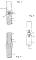
- the welding indicator shown in an axial section in FIG. 1 contains a sleeve 2 with a chamber 4, in which the additional material 6 before carrying out a Weld is arranged.
- the sleeve then contains a chamber 4 Taper 8, in which a plug 10 is located and which in comparison with the chamber 4 has a reduced cross-sectional area.
- the sleeve 2 is advantageously Made of metal, such as copper, brass or aluminum, which ensures good heat conduction is ensured.
- the material 6 is initially secured by means of the sealing plug 10 held in chamber 4.
- the sealing plug 10 suitably consists of a Heating fusible and / or soluble material, such as wax or in particular contains such.
- the plug 10 has the way for the expanding material 6th Approved.
- the sleeve 2 contains a second chamber or a riser pipe 12 for taking up the expansion mass.
- the sealing plug 10 and the additional material 6, especially after its expansion, advantageously have different colors. So the plug can For example, be white while the additional material 6 is red, so that after the Weld the expanded additional material in the riser pipe 12 due to the red color clearly recognizable and thus enables a safe visual control is.
- the sleeve 2 preferably has two lateral ones on the outside Bars 14, which ensure good stability and / or good anchoring and Locking of the welding indicator in an assigned recess or bore ensure a sleeve body.
- Fig. 2 shows the sleeve 2 in a side view, in comparison to Fig. 1 in a position rotated by 90 ° with respect to the longitudinal axis 16, the bottom of the Sleeve 2 is slightly modified, is conical. As can be seen, is in the area the inside of the sleeve 2 taper the sleeve 2 outside with a Constriction 18 provided.
- Fig. 4 shows the assembly of the welding indicator, which in a recess or Bore 22 of a partially shown fitting body 24 in the direction of arrow 26 is used.
- the fitting body 24 is part of a as an electric welding sleeve trained fittings, in the inner surface of a heating element designed as a heating coil 28 is arranged.
- a heating element designed as a heating coil 28 is arranged.
- the welding sleeve designed in this way the end of a plastic pipe to be welded inserted and The heating element is supplied with current to produce the welded connection.
- On The outer surface 30 of the fitting body 24 or the welding sleeve is a reinforcement 32 arranged.
- the recess or mounting hole 22 of the fitting body 24 is preferred stepped, the lower part according to the drawing 32, which up to the Proximity or the area of the heating element 28 is sufficient to accommodate the sleeve part the chamber 4 is provided and designed.
- the one facing the outer surface 30 according to the drawing, the upper part 36 of the recess 22 has one opposite the lower part 34 enlarged diameter.
- the welding indicator or the sleeve containing the material 6 is advantageous 2 firmly pressed into the lower part 34, so that not only a reliable mechanical Locking is reached, but optimized in a particularly expedient manner Heat transfer is ensured.
- the lower, inner end of the Sleeve 2 is at a predetermined distance 38 from heating element 28.
- the distance 38 is specified according to the invention in such a way that the melt emerges through the Recess 22 is prevented to the outside with high security.
- Fig. 6 shows an alternative embodiment of the welding indicator, the additional one Material 6 in a kinematic reversal of the first embodiment before welding is visible and after welding due to a considerable reduction in volume no longer "disappears" or from the outer surface 30 of the fitting body 24 is visible.
- the material 6 is in the outer surface 30 facing outer chamber of the sleeve 2 and is through the opening 20 after well visible from the outside.
- the sleeve 2 advantageously has one of the inner Chamber to the material 6 led heat conductor 40.
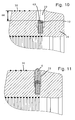
- FIG. 8 and 9 show a further embodiment of the welding indicator, whose function corresponds to the welding indicator according to FIG. 1, which, however, without Riser pipe is executed.
- the material or swelling agent 6 is in the inner chamber 4 of the Sleeve 2 arranged and the opening 42 of the sleeve 2 is by means of the sealing plug 10 closed.
- the welding indicator is in the recess 22 of the Fitting body 24 arranged such that the plug 10 within the upper part of the recess 22 at a predetermined distance 44 below the Outer surface 30 of the fitting body 24 is located.
- the sealing plug 10 has appropriately a different color, for example white, than the expanded material 6, which after welding is located in the upper part of the recess 22 and which for example the red color.
- the optical control is clear proper welding allows.
- the amount of additional expanding Material 6 and the dimension of the recess 22 are preferably predetermined in such a way 11 that, after welding, the expanded material 6 at least up to, expediently in a predetermined amount via the outer surface 30 protrudes.
- 12 and 13 show an embodiment of the welding indicator, the additional Material or swelling agent 6 in a "stable shape" in the lower part 34 of the recess 22 is inserted.
- the additional material is particularly by pressing, Drying, coating with paper or wax, in the recess 22 of the fitting body 24 used.
- 13 is the welding indicator due to the welding activated and the additional material or swelling agent 6 is at least partially also in reaches the upper part 36 of the recess 22 and is thus clearly visible from the outside.
- the additional material preferably experiences during welding as a result of Exposure to heat changes color to ensure reliable control of proper To allow welding. Basically, however, it is sufficient within the scope of Invention the design of the welding indicator in such a way that due to the heating additional material also the upper part 36 open in the area of the outer surface 30 at least partially filled out.
- the additional material or swelling agent 6 can be placed directly into the recess 22 and in particular be introduced into the inner part 34 of the same.
- the swelling agent 6 in liquid as well as in solid form or as a powder or Granulate be introduced in doses.
- the Swelling agent by means of a dissolving and / or dissolving as a result of the heating Sealing plug in the recess 22 and in particular the inner part 34 thereof be fixed.
- FIG. 14 and 15 show a further embodiment of the welding indicator similar to FIG. 12 and 13, being additionally in the upper part 36 of the recess of the fitting body 24 a display element 45 is arranged.
- the display element 45 covers according to FIG. 14 the additional one arranged in the lower, preferably tapered part 34 of the recess Material or swelling agent 6 completely.
- the display element 45 contains a display pen, the upper end of FIG. 14 below the outer surface 30 in the upper part 36 of the recess is located.
- Display element 45 moves toward outer surface 30 such that the indicator pin protrudes in a predetermined amount beyond the outer surface 30 of the fitting body 24, whereby the proper welding is displayed.
- the sweat indicator 16 shows a further embodiment of the welding indicator, the sleeve 2 of which contains comparatively long riser 46 following the inner chamber 4, in which the additional material or swelling agent 4 is arranged.
- the sweat indicator also includes a transparent cap 48 connected to the sleeve 2 for optical purposes Display.
- the transparent cap 48 offers a good one Protection for the expanded material and prevents unwanted detachment of the same. This is due to the preferably hemispherical transparent cap 48 Material expanded into the open space 50 is clearly visible all around.
- the welding indicator is inserted into the sleeve body 24 in this way and anchored therein that the transparent cap 48 over the outer surface 30 of the Sleeve body 24 protrudes.
- the swelling mass 6 expanded into the free space 50 through the transparent Cap 48 clearly visible from all sides.
- FIG. 19 there is a further embodiment of the welding indicator with a Transparent cap 48 shown.
- the transparent cap 48 advantageously contains one preferably cylindrical ring part 52, which in the recess 22 of the fitting body 24 is used.
- the additional material or swelling agent is within the ring part 52 6 arranged and covered by a partition 54 such that within the Cap 48 of free space 50 is formed, which is substantially outside the outer surface 30 of the fitting body 24 is located.
- the partition 54 also contains one Opening 56, through which the expanding when the predetermined temperature is reached Material 6 reaches the free space 50.
- Transparent cap 48 advantageously contains one in the area of the free space small bore or opening 58 to the outside for pressure equalization.
- the combination of the Sweat indicator with a fitting does not work on training it as one Welding sleeve is limited. Rather, the combination according to the invention also includes other fittings, such as saddles, tapping fittings for pipes as well as sheet-like ones Components, for example plates, or three-dimensional components, such as containers, bushings in tubs or containers or the like. Such fittings, if necessary are connected to corresponding components or are part of the same, contain heating elements that can be acted upon by electric current or voltage made of resistance wire, for example in the form of the heating coil or a heating coil.
- heating elements or the electrical Wires or conductors applied to the surface of the component to be welded be and in particular be vapor-deposited from electrically conductive material or as Metal grid or as electrically conductive carbon fibers or from electrically conductive Plastic or polymer can be formed.
- the supply of welding energy by means of the Heating element can also be done by electrical resistance heating as well by using induction or microwave technology.
Landscapes
- Engineering & Computer Science (AREA)
- Mechanical Engineering (AREA)
- Physics & Mathematics (AREA)
- Thermal Sciences (AREA)
- General Physics & Mathematics (AREA)
- Lining Or Joining Of Plastics Or The Like (AREA)
Abstract
Description
- Schmelzdruckabfall im Bereich des Schweißindikators,
- Gefahr von Lunkern,
- Drahtverschiebungen / Kurzschluß
- unterschiedliche Auslöse-Intensitäten
- komplizierte Bauformen.
- Fig. 1, 2
- in einem Längsschnitt und in einer seitlichen Ansicht eine erste Ausführungsform des als Quellindikator ausgebildeten Schweißindikators,
- Fig. 3
- den Schweißindikator gemäß Fig. 1 nach der Verschweißung,
- Fig. 4, 5
- den Schweißindikator gemäß Fig. 1 während und nach der Montage in einen Fittingkörper,
- Fig. 6, 7
- eine Ausführungsform des Schweißindikators, dessen zusätzliches Material eine Volumenreduktion erfährt,
- Fig. 8 - 11
- eine weitere Ausführungsform ähnlich Fig. 1,
- Fig. 12, 13
- eine Ausführungsform, bei welcher das zusätzliche Material in einer stabilen Form in eine Bohrung oder Ausnehmung des Fittingkörpers eingesetzt ist,
- Fig. 14, 15
- eine Ausführungsform ähnlich Fig. 12 mit einem kombinierten Anzeigestift,
- Fig. 16 - 18
- eine Ausführungsform mit einer transparenten Kappe für die optische Anzeige,
- Fig. 19
- eine Ausführungsform mit einer transparenten Kappe und einer Trennwand zwischen dem zusätzlichen Material und einem Freiraum.
- 2
- Hülse
- 4
- Kammer
- 6
- zusätzliches Material / Quellmittel
- 8
- Verjüngung in 2
- 10
- Verschlussstopfen
- 12
- Steigrohr / zweite Kammer
- 14
- seitlicher Steg von 2
- 16
- Längsachse
- 18
- Einschnürung von 2
- 20
- Öffnung von 12
- 22
- Ausnehmung / Bohrung in 24
- 24
- Fittingkörper
- 26
- Pfeil
- 28
- Heizelement / Heizwendel
- 30
- Außenfläche von 24
- 32
- Armierung
- 34
- innerer / unterer Teil von 22
- 36
- äußerer / oberer Teil von 22
- 38
- Abstand
- 40
- Wärmeleiter
- 42
- Öffnung von 2
- 44
- Abstand
- 45
- Anzeigeelement
- 46
- Steigrohr
- 48
- transparente Kappe
- 50
- Freiraum
- 52
- Ringteil
- 54
- Trennwand
- 56
- Öffnung in 54
- 58
- Bohrung in 48
Claims (10)
- Schweißindikator für ein Schweißfitting, welches einen Fittingkörper (24) aus schweißbarem Kunststoff sowie ein Heizelement (28) zur Herstellung einer Schweißverbindung mit einem Bauteil aus Kunststoff enthält, wobei der Schweißindikator insbesondere in einer Ausnehmung (22) im Bereich einer Außenfläche (30) des Fittingkörpers (24) angeordnet ist,
dadurch gekennzeichnet, dass der Schweißindikator zusätzliches Material (6) enthält, welches bei Erreichen einer vorgegebenen Temperatur eine wesentliche Volumenänderung erfährt, welche nach außen zur Anzeige gebracht wird. - Schweißindikator nach Anspruch 1, dadurch gekennzeichnet, dass die vorgegebene Temperatur zumindest näherungsweise gleich groß oder größer als die Schmelztemperatur des Kunststoffes des Fittingkörpers (24) ist und/oder dass als Volumenänderung eine Volumenexpansion oder eine Volumenreduktion vorgegeben ist, und/oder dass die Volumenänderung um einen vorgegebenen Betrag größer ist als die Volumenänderung des Kunststoffs bei Erreichen der vorgegebenen Temperatur, wobei der genannte Betrag bevorzugt wenigstens 1,2, insbesondere wenigstens 1,5, beträgt.
- Schweißindikator nach Anspruch 1 oder 2, dadurch gekennzeichnet, dass der Schweißindikator eine Hülse (2) und/oder eine insbesondere transparente Kappe (48) enthält und/oder dass das zusätzliche Material (6) in einer bevorzugt innenliegenden ersten Kammer (4) der Hülse (2) oder der Kappe (48) angeordnet ist und/oder dass das zusätzliche Material (6) mittels eines Verschlussstopfens (10) oder einer Trennwand (54) in der ersten Kammer (4) festgelegt ist, wobei der Verschlussstopfen (10) während des Schweißens, bevorzugt vor oder bei Erreichen der vorgegebenen Temperatur aufgelöst wird oder gelöst wird oder wobei die Trennwand (54) eine Öffnung (56) für den Durchtritt des Materials bei der Volumenänderung aufweist.
- Schweißindikator nach einem der Ansprüche 1 bis 3, dadurch gekennzeichnet, dass er in die Ausnehmung (22) des Fittingkörpers (4) derart eingesetzt ist und/oder in den Fittingkörper (24) derart integriert ist, dass vor dem Schweißen das zusätzliche Material (6) einen vorgegebenen Abstand (38) zum Heizelement (28) und/oder der Schweißzone aufweist.
- Schweißindikator nach einem der Ansprüche 1 bis 4, dadurch gekennzeichnet, dass die Hülse (2) eine zweite Kammer oder ein Steigrohr (12) enthält und/oder dass zwischen der zweiten Kammer bzw. dem Steigrohr (12) und der ersten Kammer (4) die Hülse (2) eine Verjüngung (8) mit reduzierter Querschnittsfläche aufweist, wobei in der Verjüngung (8) bevorzugt der Verschlussstopfen (10) angeordnet ist, und/oder dass die Hülse (2) eine zur Außenfläche (30) des Fittingkörpers (24) gerichtete Öffnung (20, 42) aufweist.
- Schweißindikator nach einem der Ansprüche 1 bis 5, dadurch gekennzeichnet, dass der Verschlussstopfen (10) eine andere Farbe aufweist als das zusätzliche Material (6), insbesondere nach dessen Volumenänderung, und/oder dass das zusätzliche Material (6) bei der Volumenänderung einen Farbumschlag erfährt.
- Schweißindikator mit einem Schweißfitting nach einem der Ansprüche 1 bis 6, dadurch gekennzeichnet, dass der Schweißindikator, insbesondere dessen Hülse (2), fest in der Ausnehmung (22) des Fittingkörpers (24) angeordnet ist und bevorzugt in die Ausnehmung (22) gepresst ist und/oder dass die Ausnehmung (22) gestuft mit einem inneren Teil (34) und einem oberen der Außenfläche (30) zugewandten äußeren Teil (36) ausgebildet ist und/oder dass die Hülse (2) in dem inneren Teil (34), welcher einen geringeren Durchmesser als der äußere Teil (36) der Ausnehmung (22) aufweist, verankert ist.
- Schweißindikator nach einem der Ansprüche 1 bis 7, dadurch gekennzeichnet, dass die Hülse (2) die Kammer (4) mit dem zusätzlichen Material (6) enthält und derart in die Ausnehmung (22) des Fittingkörpers (24) eingesetzt ist, dass die Öffnung (42) der Hülse (2) in einem vorgegebenen Abstand (44) zur Außenfläche (30) des Fittingkörpers (24) angeordnet ist, wobei zunächst die Öffnung (42) mit dem Verschlussstopfen (10) verschlossen ist und nach der Volumenexpansion das zusätzliche Material teilweise in dem zwischen der Öffnung (42) der Hülse (2) und der Außenfläche (44) liegenden Teil der Ausnehmung (22) sich befindet.
- Schweißindikator nach einem der Ansprüche 1 bis 7, dadurch gekennzeichnet, dass das zusätzliche Material (6) vor der Montage in die Ausnehmung (22) des Fittingkörpers (24) eine stabile Form aufweist und in die Ausnehmung (22) des Fittingkörpers (24) eingesetzt ist oder dass das zusätzliche Material (6) direkt in die Ausnehmung (22) eingebracht ist, wobei bevorzugt mittels des Verschlussstopfens (10) die Festlegung, insbesondere im inneren Teil (34) der Ausnehmung (22), erfolgt.
- Schweißindikator nach einem der Ansprüche 1 bis 9, dadurch gekennzeichnet, dass innerhalb der transparenten Kappe (48) ein Freiraum (50) zur Aufnahme eines Teils des expandierten zusätzlichen Materials vorgesehen ist und/oder dass die Kappe (48) zumindest teilweise über die Außenfläche (30) des Fittingkörpers (24) hinausragt.
Applications Claiming Priority (2)
| Application Number | Priority Date | Filing Date | Title |
|---|---|---|---|
| DE10228417 | 2002-06-25 | ||
| DE10228417 | 2002-06-25 |
Publications (3)
| Publication Number | Publication Date |
|---|---|
| EP1376083A2 true EP1376083A2 (de) | 2004-01-02 |
| EP1376083A3 EP1376083A3 (de) | 2006-01-11 |
| EP1376083B1 EP1376083B1 (de) | 2010-08-18 |
Family
ID=29716647
Family Applications (1)
| Application Number | Title | Priority Date | Filing Date |
|---|---|---|---|
| EP20030014257 Expired - Lifetime EP1376083B1 (de) | 2002-06-25 | 2003-06-25 | Schweissfitting mit einem Schweissindikator |
Country Status (3)
| Country | Link |
|---|---|
| EP (1) | EP1376083B1 (de) |
| AT (1) | ATE478328T1 (de) |
| DE (2) | DE50312989D1 (de) |
Cited By (1)
| Publication number | Priority date | Publication date | Assignee | Title |
|---|---|---|---|---|
| CN109140102A (zh) * | 2018-08-29 | 2019-01-04 | 浙江伟星新型建材股份有限公司 | 一种带有焊接质量指示装置的电熔管件 |
Citations (5)
| Publication number | Priority date | Publication date | Assignee | Title |
|---|---|---|---|---|
| EP0257283A1 (de) | 1986-08-29 | 1988-03-02 | Georg Fischer Aktiengesellschaft | Formtiel aus schweissbarem thermoplastischem Material |
| EP0376773A2 (de) | 1988-12-29 | 1990-07-04 | Gaz De France (Service National) | Vorrichtung zum Erfassen physikalischer Zustandsänderungen des Kunststoffes beim Schweissen einer Rohrverbindungsmuffe |
| WO1990013411A1 (en) | 1989-04-28 | 1990-11-15 | Wavin B.V. | Sleeve-shaped weld connecting piece of thermoplastic material with weld indicator element, and welded joint formed therewith |
| DE4018396C1 (en) | 1990-06-08 | 1991-10-02 | Friedrichsfeld Gmbh Keramik- Und Kunststoffwerke, 6800 Mannheim, De | Weld fitting of thermoplastic weldable material - comprises thermal conductor and cut=out section open externally with display pin and annular display gap for sealing |
| JPH03277894A (ja) | 1990-03-27 | 1991-12-09 | Sekisui Chem Co Ltd | 溶着継手 |
Family Cites Families (3)
| Publication number | Priority date | Publication date | Assignee | Title |
|---|---|---|---|---|
| CH668739A5 (de) * | 1986-01-08 | 1989-01-31 | Geberit Ag | Einrichtung mit einer kunststoff-schweissmuffe und einem anschlusskopf. |
| LU87403A1 (fr) * | 1988-12-06 | 1990-07-10 | Oreal | Procede de teinture de fibres keratiniques avec un hydroxyindole,associe a un derive quinonique |
| JP4000540B2 (ja) * | 1997-09-17 | 2007-10-31 | 日立金属株式会社 | 電気融着継手 |
-
2003
- 2003-06-25 DE DE50312989T patent/DE50312989D1/de not_active Expired - Lifetime
- 2003-06-25 AT AT03014257T patent/ATE478328T1/de active
- 2003-06-25 EP EP20030014257 patent/EP1376083B1/de not_active Expired - Lifetime
- 2003-06-25 DE DE10328761A patent/DE10328761B4/de not_active Expired - Fee Related
Patent Citations (5)
| Publication number | Priority date | Publication date | Assignee | Title |
|---|---|---|---|---|
| EP0257283A1 (de) | 1986-08-29 | 1988-03-02 | Georg Fischer Aktiengesellschaft | Formtiel aus schweissbarem thermoplastischem Material |
| EP0376773A2 (de) | 1988-12-29 | 1990-07-04 | Gaz De France (Service National) | Vorrichtung zum Erfassen physikalischer Zustandsänderungen des Kunststoffes beim Schweissen einer Rohrverbindungsmuffe |
| WO1990013411A1 (en) | 1989-04-28 | 1990-11-15 | Wavin B.V. | Sleeve-shaped weld connecting piece of thermoplastic material with weld indicator element, and welded joint formed therewith |
| JPH03277894A (ja) | 1990-03-27 | 1991-12-09 | Sekisui Chem Co Ltd | 溶着継手 |
| DE4018396C1 (en) | 1990-06-08 | 1991-10-02 | Friedrichsfeld Gmbh Keramik- Und Kunststoffwerke, 6800 Mannheim, De | Weld fitting of thermoplastic weldable material - comprises thermal conductor and cut=out section open externally with display pin and annular display gap for sealing |
Cited By (2)
| Publication number | Priority date | Publication date | Assignee | Title |
|---|---|---|---|---|
| CN109140102A (zh) * | 2018-08-29 | 2019-01-04 | 浙江伟星新型建材股份有限公司 | 一种带有焊接质量指示装置的电熔管件 |
| CN109140102B (zh) * | 2018-08-29 | 2023-09-01 | 临海伟星新型建材有限公司 | 一种带有焊接质量指示装置的电熔管件 |
Also Published As
| Publication number | Publication date |
|---|---|
| DE50312989D1 (de) | 2010-09-30 |
| DE10328761B4 (de) | 2005-06-23 |
| EP1376083B1 (de) | 2010-08-18 |
| EP1376083A3 (de) | 2006-01-11 |
| DE10328761A1 (de) | 2004-01-15 |
| ATE478328T1 (de) | 2010-09-15 |
Similar Documents
| Publication | Publication Date | Title |
|---|---|---|
| EP0173174B1 (de) | Schweissbares Verbindungselement zum Verbinden oder Anschliessen thermoplastischer Leitungselemente | |
| DE3153393C2 (de) | ||
| DE10112781A1 (de) | Glühkerze und Verfahren zum Herstellen derselben | |
| DE102012102959B4 (de) | Umgossene Heat-Pipe | |
| DE10358153A1 (de) | Verbindungsverfahren und Verbindungsanordnung für ein elektrisches Kabel mit einem Kontaktelement | |
| DE1479624A1 (de) | Artikel und Verfahren zu seiner Herstellung | |
| DE602005002281T2 (de) | Gassackgasgenerator | |
| DE2341308A1 (de) | Vorrichtung zum endverschliessen und verbinden von mineralisolierten elektrischen kabeln | |
| EP1376083A2 (de) | Schweissindikator für ein Schweissfitting | |
| EP0853267A1 (de) | Thermostatisches Ventil | |
| DE102013207714B4 (de) | Zündkerze sowie Verfahren zum Herstellen von Zündkerze | |
| DE102006002435A1 (de) | Verfahren zur Herstellung eines Gasgenerators und mittels des Verfahrens hergestellter Gasgenerator | |
| WO2019206715A1 (de) | Schmelzsicherung, gasbehälter und verfahren zum zusammenbauen einer schmelzsicherung und zum einbauen derselben in einen gasbehälter | |
| EP1444464A1 (de) | Elektrisch beheizbare glühkerze und verfahren zur herstellung einer elektrisch beheizbaren glühkerze | |
| DE10361453B3 (de) | Verschluss mit thermischer Sicherungsfunktion | |
| DE102013002363B4 (de) | Gassackeinheit und Halteteil zur Verwendung in einer solchen Gassackeinheit | |
| DE102009025425B4 (de) | Elektrische Trennvorrichtung sowie Fahrzeug damit | |
| EP3128806B1 (de) | Heizelement für einen strömungskanal oder ein formnest und spritzgiessdüse mit einem solchen heizelement | |
| DE19960585A1 (de) | Heizvorrichtung mit unterteiltem Mantelrohr | |
| DE2846767C2 (de) | Vorrichtung zum Verbinden von Rohrenden | |
| EP2642831A1 (de) | Plasma-Elektrode für einen Plasma-Lichtbogenbrenner und Verfahren zur Herstellung | |
| DE102007058639A1 (de) | Kerzenattrappe sowie Verfahren zu deren Herstellung | |
| WO2005064178A1 (de) | Verschluss mit thermischer sicherungsfunktion | |
| DE202007012870U1 (de) | Kerze | |
| DE10126272C2 (de) | Vorrichtung zur Verdampfung eines Fluids, insbesondere eines Nebel- oder Löschfluids |
Legal Events
| Date | Code | Title | Description |
|---|---|---|---|
| PUAI | Public reference made under article 153(3) epc to a published international application that has entered the european phase |
Free format text: ORIGINAL CODE: 0009012 |
|
| AK | Designated contracting states |
Kind code of ref document: A2 Designated state(s): AT BE BG CH CY CZ DE DK EE ES FI FR GB GR HU IE IT LI LU MC NL PT RO SE SI SK TR |
|
| AX | Request for extension of the european patent |
Extension state: AL LT LV MK |
|
| PUAL | Search report despatched |
Free format text: ORIGINAL CODE: 0009013 |
|
| AK | Designated contracting states |
Kind code of ref document: A3 Designated state(s): AT BE BG CH CY CZ DE DK EE ES FI FR GB GR HU IE IT LI LU MC NL PT RO SE SI SK TR |
|
| AX | Request for extension of the european patent |
Extension state: AL LT LV MK |
|
| AKX | Designation fees paid |
Designated state(s): AT BE BG CH CY CZ DE DK EE ES FI FR GB GR HU IE IT LI LU MC NL PT RO SE SI SK TR |
|
| 17P | Request for examination filed |
Effective date: 20060712 |
|
| D17P | Request for examination filed (deleted) | ||
| R17P | Request for examination filed (corrected) |
Effective date: 20060712 |
|
| 17Q | First examination report despatched |
Effective date: 20080828 |
|
| GRAP | Despatch of communication of intention to grant a patent |
Free format text: ORIGINAL CODE: EPIDOSNIGR1 |
|
| RTI1 | Title (correction) |
Free format text: WELDING SOCKET WITH A FUSION INDICATOR |
|
| RIC1 | Information provided on ipc code assigned before grant |
Ipc: B29C 65/02 20060101ALI20100407BHEP Ipc: B29C 65/34 20060101ALI20100407BHEP Ipc: G01K 11/12 20060101ALI20100407BHEP Ipc: G01K 11/06 20060101AFI20100407BHEP |
|
| GRAS | Grant fee paid |
Free format text: ORIGINAL CODE: EPIDOSNIGR3 |
|
| GRAA | (expected) grant |
Free format text: ORIGINAL CODE: 0009210 |
|
| AK | Designated contracting states |
Kind code of ref document: B1 Designated state(s): AT BE BG CH CY CZ DE DK EE ES FI FR GB GR HU IE IT LI LU MC NL PT RO SE SI SK TR |
|
| REG | Reference to a national code |
Ref country code: GB Ref legal event code: FG4D Free format text: NOT ENGLISH |
|
| REG | Reference to a national code |
Ref country code: CH Ref legal event code: EP |
|
| REG | Reference to a national code |
Ref country code: IE Ref legal event code: FG4D Free format text: LANGUAGE OF EP DOCUMENT: GERMAN |
|
| REF | Corresponds to: |
Ref document number: 50312989 Country of ref document: DE Date of ref document: 20100930 Kind code of ref document: P |
|
| REG | Reference to a national code |
Ref country code: CH Ref legal event code: NV Representative=s name: KAMINSKI HARMANN PATENTANWAELTE EST. |
|
| REG | Reference to a national code |
Ref country code: NL Ref legal event code: VDEP Effective date: 20100818 |
|
| REG | Reference to a national code |
Ref country code: GR Ref legal event code: EP Ref document number: 20100402665 Country of ref document: GR |
|
| PG25 | Lapsed in a contracting state [announced via postgrant information from national office to epo] |
Ref country code: FI Free format text: LAPSE BECAUSE OF FAILURE TO SUBMIT A TRANSLATION OF THE DESCRIPTION OR TO PAY THE FEE WITHIN THE PRESCRIBED TIME-LIMIT Effective date: 20100818 |
|
| PG25 | Lapsed in a contracting state [announced via postgrant information from national office to epo] |
Ref country code: CY Free format text: LAPSE BECAUSE OF FAILURE TO SUBMIT A TRANSLATION OF THE DESCRIPTION OR TO PAY THE FEE WITHIN THE PRESCRIBED TIME-LIMIT Effective date: 20100818 Ref country code: PT Free format text: LAPSE BECAUSE OF FAILURE TO SUBMIT A TRANSLATION OF THE DESCRIPTION OR TO PAY THE FEE WITHIN THE PRESCRIBED TIME-LIMIT Effective date: 20101220 Ref country code: SI Free format text: LAPSE BECAUSE OF FAILURE TO SUBMIT A TRANSLATION OF THE DESCRIPTION OR TO PAY THE FEE WITHIN THE PRESCRIBED TIME-LIMIT Effective date: 20100818 Ref country code: BG Free format text: LAPSE BECAUSE OF FAILURE TO SUBMIT A TRANSLATION OF THE DESCRIPTION OR TO PAY THE FEE WITHIN THE PRESCRIBED TIME-LIMIT Effective date: 20101118 |
|
| REG | Reference to a national code |
Ref country code: IE Ref legal event code: FD4D |
|
| PG25 | Lapsed in a contracting state [announced via postgrant information from national office to epo] |
Ref country code: NL Free format text: LAPSE BECAUSE OF FAILURE TO SUBMIT A TRANSLATION OF THE DESCRIPTION OR TO PAY THE FEE WITHIN THE PRESCRIBED TIME-LIMIT Effective date: 20100818 Ref country code: SE Free format text: LAPSE BECAUSE OF FAILURE TO SUBMIT A TRANSLATION OF THE DESCRIPTION OR TO PAY THE FEE WITHIN THE PRESCRIBED TIME-LIMIT Effective date: 20100818 |
|
| PG25 | Lapsed in a contracting state [announced via postgrant information from national office to epo] |
Ref country code: IE Free format text: LAPSE BECAUSE OF FAILURE TO SUBMIT A TRANSLATION OF THE DESCRIPTION OR TO PAY THE FEE WITHIN THE PRESCRIBED TIME-LIMIT Effective date: 20100818 Ref country code: DK Free format text: LAPSE BECAUSE OF FAILURE TO SUBMIT A TRANSLATION OF THE DESCRIPTION OR TO PAY THE FEE WITHIN THE PRESCRIBED TIME-LIMIT Effective date: 20100818 |
|
| PG25 | Lapsed in a contracting state [announced via postgrant information from national office to epo] |
Ref country code: SK Free format text: LAPSE BECAUSE OF FAILURE TO SUBMIT A TRANSLATION OF THE DESCRIPTION OR TO PAY THE FEE WITHIN THE PRESCRIBED TIME-LIMIT Effective date: 20100818 Ref country code: EE Free format text: LAPSE BECAUSE OF FAILURE TO SUBMIT A TRANSLATION OF THE DESCRIPTION OR TO PAY THE FEE WITHIN THE PRESCRIBED TIME-LIMIT Effective date: 20100818 Ref country code: CZ Free format text: LAPSE BECAUSE OF FAILURE TO SUBMIT A TRANSLATION OF THE DESCRIPTION OR TO PAY THE FEE WITHIN THE PRESCRIBED TIME-LIMIT Effective date: 20100818 Ref country code: RO Free format text: LAPSE BECAUSE OF FAILURE TO SUBMIT A TRANSLATION OF THE DESCRIPTION OR TO PAY THE FEE WITHIN THE PRESCRIBED TIME-LIMIT Effective date: 20100818 |
|
| PLBE | No opposition filed within time limit |
Free format text: ORIGINAL CODE: 0009261 |
|
| STAA | Information on the status of an ep patent application or granted ep patent |
Free format text: STATUS: NO OPPOSITION FILED WITHIN TIME LIMIT |
|
| PG25 | Lapsed in a contracting state [announced via postgrant information from national office to epo] |
Ref country code: ES Free format text: LAPSE BECAUSE OF FAILURE TO SUBMIT A TRANSLATION OF THE DESCRIPTION OR TO PAY THE FEE WITHIN THE PRESCRIBED TIME-LIMIT Effective date: 20101129 |
|
| 26N | No opposition filed |
Effective date: 20110519 |
|
| REG | Reference to a national code |
Ref country code: DE Ref legal event code: R097 Ref document number: 50312989 Country of ref document: DE Effective date: 20110519 |
|
| BERE | Be: lapsed |
Owner name: FRIATEC A.G. Effective date: 20110630 |
|
| REG | Reference to a national code |
Ref country code: FR Ref legal event code: ST Effective date: 20120229 |
|
| PG25 | Lapsed in a contracting state [announced via postgrant information from national office to epo] |
Ref country code: BE Free format text: LAPSE BECAUSE OF NON-PAYMENT OF DUE FEES Effective date: 20110630 |
|
| PG25 | Lapsed in a contracting state [announced via postgrant information from national office to epo] |
Ref country code: FR Free format text: LAPSE BECAUSE OF NON-PAYMENT OF DUE FEES Effective date: 20110630 |
|
| PGFP | Annual fee paid to national office [announced via postgrant information from national office to epo] |
Ref country code: AT Payment date: 20120529 Year of fee payment: 10 |
|
| PG25 | Lapsed in a contracting state [announced via postgrant information from national office to epo] |
Ref country code: MC Free format text: LAPSE BECAUSE OF NON-PAYMENT OF DUE FEES Effective date: 20110630 |
|
| PG25 | Lapsed in a contracting state [announced via postgrant information from national office to epo] |
Ref country code: LU Free format text: LAPSE BECAUSE OF NON-PAYMENT OF DUE FEES Effective date: 20110625 |
|
| PGFP | Annual fee paid to national office [announced via postgrant information from national office to epo] |
Ref country code: GB Payment date: 20130619 Year of fee payment: 11 Ref country code: DE Payment date: 20130627 Year of fee payment: 11 Ref country code: CH Payment date: 20130612 Year of fee payment: 11 |
|
| PGFP | Annual fee paid to national office [announced via postgrant information from national office to epo] |
Ref country code: GR Payment date: 20130514 Year of fee payment: 11 Ref country code: TR Payment date: 20130521 Year of fee payment: 11 Ref country code: IT Payment date: 20130620 Year of fee payment: 11 |
|
| PG25 | Lapsed in a contracting state [announced via postgrant information from national office to epo] |
Ref country code: HU Free format text: LAPSE BECAUSE OF FAILURE TO SUBMIT A TRANSLATION OF THE DESCRIPTION OR TO PAY THE FEE WITHIN THE PRESCRIBED TIME-LIMIT Effective date: 20100818 |
|
| REG | Reference to a national code |
Ref country code: DE Ref legal event code: R119 Ref document number: 50312989 Country of ref document: DE |
|
| REG | Reference to a national code |
Ref country code: CH Ref legal event code: PL |
|
| REG | Reference to a national code |
Ref country code: AT Ref legal event code: MM01 Ref document number: 478328 Country of ref document: AT Kind code of ref document: T Effective date: 20140625 |
|
| GBPC | Gb: european patent ceased through non-payment of renewal fee |
Effective date: 20140625 |
|
| REG | Reference to a national code |
Ref country code: GR Ref legal event code: ML Ref document number: 20100402665 Country of ref document: GR Effective date: 20150105 |
|
| REG | Reference to a national code |
Ref country code: DE Ref legal event code: R119 Ref document number: 50312989 Country of ref document: DE Effective date: 20150101 |
|
| PG25 | Lapsed in a contracting state [announced via postgrant information from national office to epo] |
Ref country code: DE Free format text: LAPSE BECAUSE OF NON-PAYMENT OF DUE FEES Effective date: 20150101 Ref country code: LI Free format text: LAPSE BECAUSE OF NON-PAYMENT OF DUE FEES Effective date: 20140630 Ref country code: IT Free format text: LAPSE BECAUSE OF NON-PAYMENT OF DUE FEES Effective date: 20140625 Ref country code: CH Free format text: LAPSE BECAUSE OF NON-PAYMENT OF DUE FEES Effective date: 20140630 |
|
| PG25 | Lapsed in a contracting state [announced via postgrant information from national office to epo] |
Ref country code: GB Free format text: LAPSE BECAUSE OF NON-PAYMENT OF DUE FEES Effective date: 20140625 Ref country code: AT Free format text: LAPSE BECAUSE OF NON-PAYMENT OF DUE FEES Effective date: 20140625 Ref country code: GR Free format text: LAPSE BECAUSE OF NON-PAYMENT OF DUE FEES Effective date: 20150105 |
|
| PG25 | Lapsed in a contracting state [announced via postgrant information from national office to epo] |
Ref country code: TR Free format text: LAPSE BECAUSE OF NON-PAYMENT OF DUE FEES Effective date: 20140625 |