EP1375971A1 - Enceinte de boíte de vitesses et boíte de vitesses pilotée équipée d'une telle enceinte - Google Patents
Enceinte de boíte de vitesses et boíte de vitesses pilotée équipée d'une telle enceinte Download PDFInfo
- Publication number
- EP1375971A1 EP1375971A1 EP03291566A EP03291566A EP1375971A1 EP 1375971 A1 EP1375971 A1 EP 1375971A1 EP 03291566 A EP03291566 A EP 03291566A EP 03291566 A EP03291566 A EP 03291566A EP 1375971 A1 EP1375971 A1 EP 1375971A1
- Authority
- EP
- European Patent Office
- Prior art keywords
- gearbox
- casing
- enclosure according
- oil supply
- bowl
- Prior art date
- Legal status (The legal status is an assumption and is not a legal conclusion. Google has not performed a legal analysis and makes no representation as to the accuracy of the status listed.)
- Granted
Links
- 230000005540 biological transmission Effects 0.000 title 1
- 238000007789 sealing Methods 0.000 claims description 4
- 238000003466 welding Methods 0.000 claims description 2
- 239000003921 oil Substances 0.000 description 33
- 238000005461 lubrication Methods 0.000 description 5
- 241000208199 Buxus sempervirens Species 0.000 description 1
- 230000001133 acceleration Effects 0.000 description 1
- 229910052782 aluminium Inorganic materials 0.000 description 1
- XAGFODPZIPBFFR-UHFFFAOYSA-N aluminium Chemical compound [Al] XAGFODPZIPBFFR-UHFFFAOYSA-N 0.000 description 1
- 230000005587 bubbling Effects 0.000 description 1
- 238000004519 manufacturing process Methods 0.000 description 1
- 229910052751 metal Inorganic materials 0.000 description 1
- 239000002184 metal Substances 0.000 description 1
- 239000013589 supplement Substances 0.000 description 1
Images

Classifications
-
- F—MECHANICAL ENGINEERING; LIGHTING; HEATING; WEAPONS; BLASTING
- F16—ENGINEERING ELEMENTS AND UNITS; GENERAL MEASURES FOR PRODUCING AND MAINTAINING EFFECTIVE FUNCTIONING OF MACHINES OR INSTALLATIONS; THERMAL INSULATION IN GENERAL
- F16H—GEARING
- F16H57/00—General details of gearing
- F16H57/04—Features relating to lubrication or cooling or heating
- F16H57/042—Guidance of lubricant
- F16H57/0421—Guidance of lubricant on or within the casing, e.g. shields or baffles for collecting lubricant, tubes, pipes, grooves, channels or the like
- F16H57/0426—Means for guiding lubricant into an axial channel of a shaft
-
- F—MECHANICAL ENGINEERING; LIGHTING; HEATING; WEAPONS; BLASTING
- F16—ENGINEERING ELEMENTS AND UNITS; GENERAL MEASURES FOR PRODUCING AND MAINTAINING EFFECTIVE FUNCTIONING OF MACHINES OR INSTALLATIONS; THERMAL INSULATION IN GENERAL
- F16H—GEARING
- F16H57/00—General details of gearing
- F16H57/04—Features relating to lubrication or cooling or heating
- F16H57/042—Guidance of lubricant
- F16H57/043—Guidance of lubricant within rotary parts, e.g. axial channels or radial openings in shafts
-
- F—MECHANICAL ENGINEERING; LIGHTING; HEATING; WEAPONS; BLASTING
- F16—ENGINEERING ELEMENTS AND UNITS; GENERAL MEASURES FOR PRODUCING AND MAINTAINING EFFECTIVE FUNCTIONING OF MACHINES OR INSTALLATIONS; THERMAL INSULATION IN GENERAL
- F16H—GEARING
- F16H57/00—General details of gearing
- F16H57/04—Features relating to lubrication or cooling or heating
- F16H57/045—Lubricant storage reservoirs, e.g. reservoirs in addition to a gear sump for collecting lubricant in the upper part of a gear case
Definitions
- the present invention relates to an enclosure gearbox including an enclosure of gearbox including a housing, at minus an opening in the bottom of the casing adapted to receive the end of a line of hollow shaft of said box, a first bowl adapted to receive and contain oil contained inside the gearbox in operation and attached to the inside of the housing being in contact with the bottom of the housing, and a cover attached to the bottom of the casing outside of it.
- piloted gearboxes that is to say those whose internal control of mechanical elements, such as synchronizers, pinion type gears which constitute it, do not not just through parts mechanical but electrically and / or hydraulically.
- the lubrication of mechanical elements which constitute a mechanical gearbox is generally provided by projections oils generated by the bubbling of gearbox gears in operation. These projections usually go on the walls gearbox housings for go back down to the bottom of these. Generally, a chute housed in ribs on a side wall internal of a housing is used to capture this oil and route it to the front side of the gearbox then inwards trees.
- the opening in the housing to receive the control actuator the gearbox requires reducing considerably the length of the chute.
- the amount of oil entering the chute is no longer sufficient and therefore there is a may no longer provide lubrication correct mechanical elements of the gearbox speeds.
- the architecture of a mechanical controlled speeds can be such that internal mechanics is framed by bearings. There is then a risk of planing when the motor vehicle which is equipped of such a box makes a turn. Oil present in the gearbox undergoes a acceleration which drives it towards the engine. The rear part of the gearbox is not then no longer supplied with oil. By “part rear "of the gearbox we hear the bottom of the casing and the bottom of the gearbox on the left wheel side, i.e. the opposite side to the engine.
- the architecture of a mechanical driven speeds can be such that it does not allow housing the chute at mounting.
- the object of the invention is then to solve all or part of the above problems.
- the invention relates to a gearbox enclosure including a housing, at least one opening in the bottom of the housing adapted to receive the end of a hollow shaft line of said box, a first bowl adapted to receive and contain oil contained inside the gearbox in operation and attached to the inside of the housing being in contact with the bottom of the housing, and a cover attached to the bottom of the casing outside of it characterized in that it includes a second bowl also suitable for receiving and containing the oil inside the box operating speeds and fixed at the inside of the housing being in contact with the bottom of the housing and in that said first and second cuvettes are positioned above of the hollow shaft line of the box operating speeds and lead to the outside of the bottom of the housing on a part oil supply including a chute leading to a tubing adapted to be housed in the hollow shaft line.
- said first and second bowls are arranged symmetrically by compared to the hollow shaft line.
- the first bowl has an inclined wall at an angle ⁇ substantially of the order of 5 ° by relative to the perpendicular from the bottom of said bowl.
- the oil supply is thus correctly ensured in normal operation of the gearbox. Normal operation of the gearbox is for example when a vehicle fitted with it performs a driving at a steady speed on a road substantially horizontal.
- the second bowl has a wall inclined at an angle ⁇ 'between 10 and 15 ° from the perpendicular from the bottom of said bowl.
- the oil supply piece is, in a first embodiment, previously fixed at cover, preferably by welding, in a second embodiment, independent of cover and includes, on the stop intended for cooperate with the inner face of the cover, a sealing element capable of reducing the oil leaks between cover and workpiece oil supply.
- the casing comprises bosses suitable for housing in lights practiced in each of the bowls.
- the fixing of the cuvettes is made by clipping directly to the oil supply piece.
- the bottom of the housing has two other suitable openings to each receive the end of a line shaft.
- a wall side of the housing has an opening adapted to receive an actuator from the box of speeds.
- the invention also relates to a box of mechanical controlled speeds including a enclosure described above and at least one actuator.
- the hollow shaft line receiving the tubing of the supply room of oil is the primary shaft line.
- the enclosure according to invention 1 is shown below before its mounting on the internal mechanics of the box of speeds, i.e. the trees, the gear, synchronizers ..., which itself is already mounted and installed in the other housing gearbox that closes the gearbox speeds with the enclosure according to the invention.
- the enclosure according to the invention includes all first an aluminum gearbox housing 2 of which the bottom 21 has three circular openings 210,211,212 each adapted to receive the end of a box tree line speeds.
- This casing usually presents a plurality of holes 22 reported on the edge open 23 adapted to receive screws fixing not shown of the enclosure with the other housing during the final assembly of the gearbox.
- the side wall 24 of this housing also has an opening rectangular 241 adapted to receive a actuator not shown here which allows the control of synchronizers and therefore control of the box.
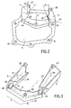
- first bowl 3 Inside this casing 2 are fixed two bowls 3,4 of elongated shape, substantially the same length and being in contact with the bottom 21 of the casing 2.
- the first bowl 3 is located so that its lateral face 31 opposite to that in contact with the bottom of the housing is positioned at the edge of opening 241 which receives the actuator gearbox control.
- Each of these first 3 and second 4 cuvettes respectively presents a oblong opening 32, 42 which comes position around a boss 25 formed at inside the housing.
- the first bowl 3 has a wall lateral 33 inclined by an angle ⁇ of the order of 5 ° relative to the bottom 34 of the bowl which, when the gearbox is in normal operation, is horizontal (depending the X axis in Figure 2). This tilt provides an oil supply to sure when the gearbox is in normal running.
- the second bowl 4 has a wall lateral 43 inclined by an angle ⁇ of the order of 10 ° relative to the bottom 44 of the bowl which, when the gearbox is in normal operation, is horizontal (depending the X axis in Figure 2).
- This tilt allows to supplement the oil supply of the first bowl 3, when the speeds is in normal operation, and also to ensure the supply of oil during planings that take place for example when the vehicle fitted with it performs a turn.
- the enclosure further comprises a cover 5 made of sheet metal fixed to the casing 2, by means of fixing screws not shown housed in the fixing holes 51 made at the periphery of the lid.
- a oil supply piece 6 is welded to this cover 5.
- This oil supply piece 6 has a chute 61 in the form of two identical inclined slopes which converge towards a central tube 62 opening onto the other side and whose free end is each extended by a hook 63.
- these hooks 63 allow the clipping of portions tubular 35,45 which open respectively bowls 3 and 4.
- basins 3 and 4 in the casing 2 is such that whatever the operating condition of the gearbox speeds, i.e. whatever the position of the tree line (s) relative to horizontally or in other words whatever either turning the vehicle equipped with it during taxiing, these are located above the hollow shaft line whose end opens out in the light 210.
- the oil supply part 6, as above described, is separate from the cover 5.
- the oil supply part 6 comprises a sealing element intended to be pressure when screwing the cover 5 on enclosure 1.
- the sealing element is then preferably mounted on the edge of the part 6 intended to cooperate with the inner face of the cover 5 so as to advantageously allow reduced oil leakage between cover 5 and the oil supply piece 6.
- the second mode of realization facilitates the assembly operation. In it’s easier to clip tubular portions 35.45 of the bowls 3.4 on the hooks 63 of the oil supply piece 6 without the presence of cover 5, which reduces considerably the visibility of the parts to cliper.
- the enclosure 1 which has just been described allows certain lubrication of the entire internal mechanics of the gearbox, what whatever the operation of the speeds, i.e. driving conditions of the motor vehicle fitted with it.
- the oil splashes generated by the set of gears in the box speeds necessarily fill the bowls 3 and 4.
- the oil thus contained flows out through tubular portions 35 and 45 then at through chute 61 and finally through the tubing 62 located in the hollow shaft line which itself pierced with channels in a manner known in itself directly feeds the fixed gears and / or madmen mounted on the tree line.
- the invention which has just been described allows ensure safe lubrication of the internal mechanics of a gearbox fitted of enclosure 1 and whatever the operating conditions of this box, that is to say whatever the conditions of the vehicle fitted with it ( "normal” operation, in a situation of backspin .7)
- the assembly of the enclosure does does not harm the final one of the box because it is a operation carried out by prior assembly, this which is advantageous in terms of time manufacturing.
- bowls can be completely attached to the gearbox housing and not partly clipped to the oil supply piece. These bowls can take different forms ....
Landscapes
- Engineering & Computer Science (AREA)
- General Engineering & Computer Science (AREA)
- Mechanical Engineering (AREA)
- General Details Of Gearings (AREA)
- Toys (AREA)
- Transmitters (AREA)
- Lubrication Details And Ventilation Of Internal Combustion Engines (AREA)
Abstract
Description
- les figures 1a et 1b sont des vues en perspective du carter de boite faisant partie de l'enceinte selon l'invention;
- la figure 2 est une vue de derrière du couvercle faisant partie de l'enceinte selon l'invention;
- la figure 3 est une vue en perspective du montage des cuvettes et de la pièce d'amenée d'huile selon l'invention.
- on place chacune des cuvettes 3 et 4 à l'intérieur du carter 2 en s'assurant que les bossages 25 viennent se loger respectivement dans les lumières 32 et 42 afin d'une part de positionner très précisément les cuvettes 3 et 4 et et d'autre part que leurs portions tubulaires 35, 45 débouchent sur la face extérieure du fond 21 du carter;
- on vient réaliser le clippage des portions tubulaires 35,45 des cuvettes 3,4 avec les crochets 63 de la pièce d'amenée d'huile 6;
- on fixe définitivement le couvercle 5 au carter de boite de vitesses 2 par vissage.
Claims (12)
- Enceinte (1) de boite de vitesses comprenant un carter (2), au moins une ouverture (210) pratiquée dans le fond (21) du carter adaptée pour recevoir l'extrémité d'une ligne d'arbre creux de ladite boite, une première cuvette (3) adaptée pour recevoir et contenir de l'huile contenue à l'intérieur de la boite de vitesses en fonctionnement et fixée à l'intérieur du carter en étant en contact avec le fond (21) du carter, et un couvercle (5) fixé au fond du carter à l'extérieur de celui-ci caractérisée en ce que elle comprend une seconde cuvette (4) également adaptée pour recevoir et contenir de l'huile contenue à l'intérieur de la boite de vitesses en fonctionnement et fixée à l'intérieur du carter en étant en contact avec le fond (21) du carter et en ce que lesdites première (3) et seconde (4) cuvettes sont positionnées au-dessus de la ligne d'arbre creux de la boite de vitesses en fonctionnement et débouchent à l'extérieur du fond (21) du carter (2) sur une pièce d'amenée d'huile (6) comprenant une goulotte (61) débouchant sur une tubulure (62) adaptée pour être logée dans la ligne d'arbre creux.
- Enceinte selon la revendication 1, caractérisée en ce que lesdites première (3) et seconde (4) cuvettes sont disposées symétriquement par rapport à la ligne d'arbre creux.
- Enceinte selon la revendication 2, caractérisée en ce que la première (3) cuvette présente une paroi (33) inclinée d'un angle α sensiblement de l'ordre de 5° par rapport à la perpendiculaire du fond (34) de ladite cuvette.
- Enceinte selon l'une quelconque des revendications précédentes, caractérisée en ce que la deuxième cuvette (4) présente une paroi (43) inclinée d'un angle α' compris entre 10 et 15° par rapport à la perpendiculaire du fond (44) de ladite cuvette.
- Enceinte selon l'une quelconque des revendications précédentes, caractérisée en ce que la pièce d'amenée d'huile (6) est préalablement fixée au couvercle, de préférence par soudage.
- Enceinte selon l'une quelconque des revendications 1 à 4, caractérisée en ce que la pièce d'amenée d'huile (6) est indépendante du couvercle (5) et comprend, sur l'arête destinée à coopérer avec la face intérieure du couvercle (5), un élément d'étanchéité apte à réduire les fuites d'huile entre le couvercle (5) et la pièce d'amenée d'huile (6).
- Enceinte selon l'une quelconque des revendications précédentes, caractérisée en ce que le carter comprend des bossages (25) adaptés pour se loger dans des lumières (32,42) pratiquées dans chacune des cuvettes.
- Enceinte selon l'une quelconque des revendications précédentes, caractérisée en ce que la fixation des cuvettes est réalisée par clippage directement à la pièce d'amenée d'huile.
- Enceinte selon l'une quelconque des revendications précédentes, caractérisée en ce que le fond (21) du carter présente deux autres ouvertures (211,212) adaptées pour recevoir chacune l'extrémité d'une ligne d'arbre.
- Enceinte selon l'une quelconque des revendications précédentes, caractérisée en ce qu'une paroi latérale (24) du carter présente une ouverture (241) adaptée pour recevoir un actionneur de la boite de vitesses.
- Boite de vitesses mécanique pilotée comprenant une enceinte selon la revendication 10 et au moins un actionneur.
- Boite selon la revendication 11, caractérisée en ce que la ligne d'arbre creux recevant la tubulure (62) de la pièce d'amenée d'huile est la ligne d'arbre primaire.
Applications Claiming Priority (2)
| Application Number | Priority Date | Filing Date | Title |
|---|---|---|---|
| FR0208083A FR2841623B1 (fr) | 2002-06-28 | 2002-06-28 | Enceinte de boite de vitesses et boitee de vitesses pilotee equipee d'une telle enceinte |
| FR0208083 | 2002-06-28 |
Publications (2)
| Publication Number | Publication Date |
|---|---|
| EP1375971A1 true EP1375971A1 (fr) | 2004-01-02 |
| EP1375971B1 EP1375971B1 (fr) | 2005-07-27 |
Family
ID=29717129
Family Applications (1)
| Application Number | Title | Priority Date | Filing Date |
|---|---|---|---|
| EP03291566A Expired - Lifetime EP1375971B1 (fr) | 2002-06-28 | 2003-06-25 | Enceinte de boíte de vitesses et boíte de vitesses pilotée équipée d'une telle enceinte |
Country Status (5)
| Country | Link |
|---|---|
| EP (1) | EP1375971B1 (fr) |
| AT (1) | ATE300689T1 (fr) |
| DE (1) | DE60301095T2 (fr) |
| ES (1) | ES2243872T3 (fr) |
| FR (1) | FR2841623B1 (fr) |
Cited By (3)
| Publication number | Priority date | Publication date | Assignee | Title |
|---|---|---|---|---|
| FR2861151A1 (fr) * | 2003-10-16 | 2005-04-22 | Toyota Motor Co Ltd | Dispositif d'alimentation en huile |
| EP1907729B1 (fr) * | 2005-07-28 | 2011-04-13 | Toyota Jidosha Kabushiki Kaisha | Mecanisme d'entrainement et vehicule a moteur equipe de ce mecanisme d'entrainement |
| CN110805689A (zh) * | 2019-11-28 | 2020-02-18 | 重庆清平机械有限责任公司 | 用于电动汽车的高功率密度电机齿轮箱机构 |
Citations (6)
| Publication number | Priority date | Publication date | Assignee | Title |
|---|---|---|---|---|
| US3529698A (en) * | 1967-05-05 | 1970-09-22 | Gen Electric | Self-operating lubrication system for gear drive units |
| GB2041117A (en) * | 1979-01-23 | 1980-09-03 | Nissan Motor | Lubrication of a transmission |
| US4644815A (en) * | 1982-05-21 | 1987-02-24 | Toyota Jidosha Kabushiki Kaisha | Lubrication device in transmissions |
| FR2740853A1 (fr) * | 1995-11-07 | 1997-05-09 | Peugeot | Dispositif de lubrification dynamique d'un palier de guidage pour arbre de moteur electrique |
| JPH11218213A (ja) * | 1998-02-04 | 1999-08-10 | Honda Motor Co Ltd | 変速機の潤滑装置 |
| US20010008194A1 (en) * | 2000-01-17 | 2001-07-19 | Honda Giken Kogyo Kabushiki Kaisha, Tokyo, Japan | Fluid supply system |
-
2002
- 2002-06-28 FR FR0208083A patent/FR2841623B1/fr not_active Expired - Fee Related
-
2003
- 2003-06-25 EP EP03291566A patent/EP1375971B1/fr not_active Expired - Lifetime
- 2003-06-25 ES ES03291566T patent/ES2243872T3/es not_active Expired - Lifetime
- 2003-06-25 AT AT03291566T patent/ATE300689T1/de not_active IP Right Cessation
- 2003-06-25 DE DE60301095T patent/DE60301095T2/de not_active Expired - Lifetime
Patent Citations (6)
| Publication number | Priority date | Publication date | Assignee | Title |
|---|---|---|---|---|
| US3529698A (en) * | 1967-05-05 | 1970-09-22 | Gen Electric | Self-operating lubrication system for gear drive units |
| GB2041117A (en) * | 1979-01-23 | 1980-09-03 | Nissan Motor | Lubrication of a transmission |
| US4644815A (en) * | 1982-05-21 | 1987-02-24 | Toyota Jidosha Kabushiki Kaisha | Lubrication device in transmissions |
| FR2740853A1 (fr) * | 1995-11-07 | 1997-05-09 | Peugeot | Dispositif de lubrification dynamique d'un palier de guidage pour arbre de moteur electrique |
| JPH11218213A (ja) * | 1998-02-04 | 1999-08-10 | Honda Motor Co Ltd | 変速機の潤滑装置 |
| US20010008194A1 (en) * | 2000-01-17 | 2001-07-19 | Honda Giken Kogyo Kabushiki Kaisha, Tokyo, Japan | Fluid supply system |
Non-Patent Citations (1)
| Title |
|---|
| PATENT ABSTRACTS OF JAPAN vol. 1999, no. 13 30 November 1999 (1999-11-30) * |
Cited By (4)
| Publication number | Priority date | Publication date | Assignee | Title |
|---|---|---|---|---|
| FR2861151A1 (fr) * | 2003-10-16 | 2005-04-22 | Toyota Motor Co Ltd | Dispositif d'alimentation en huile |
| EP1907729B1 (fr) * | 2005-07-28 | 2011-04-13 | Toyota Jidosha Kabushiki Kaisha | Mecanisme d'entrainement et vehicule a moteur equipe de ce mecanisme d'entrainement |
| US8267223B2 (en) | 2005-07-28 | 2012-09-18 | Toyota Jidosha Kabushiki Kaisha | Drive assembly and motor vehicle equipped with drive assembly |
| CN110805689A (zh) * | 2019-11-28 | 2020-02-18 | 重庆清平机械有限责任公司 | 用于电动汽车的高功率密度电机齿轮箱机构 |
Also Published As
| Publication number | Publication date |
|---|---|
| DE60301095T2 (de) | 2006-05-24 |
| EP1375971B1 (fr) | 2005-07-27 |
| FR2841623B1 (fr) | 2004-07-23 |
| ES2243872T3 (es) | 2005-12-01 |
| ATE300689T1 (de) | 2005-08-15 |
| FR2841623A1 (fr) | 2004-01-02 |
| DE60301095D1 (de) | 2005-09-01 |
Similar Documents
| Publication | Publication Date | Title |
|---|---|---|
| WO2013030478A1 (fr) | Dispositif de liaison d'une colonne de direction avec un boitier de direction. | |
| EP3879133B1 (fr) | Double embrayage humide | |
| FR2740853A1 (fr) | Dispositif de lubrification dynamique d'un palier de guidage pour arbre de moteur electrique | |
| EP1375971B1 (fr) | Enceinte de boíte de vitesses et boíte de vitesses pilotée équipée d'une telle enceinte | |
| FR2458419A1 (fr) | Perfectionnement a une transmission automatique a essieu transversal | |
| EP0124433B1 (fr) | Boîtier amovible de distribution pour moteur à explosion ou à combustion | |
| FR3110879A1 (fr) | Double embrayage humide | |
| FR2589968A1 (fr) | Dispositif de graissage d'une commande d'arbre d'un vehicule automobile | |
| EP0730991B2 (fr) | Dispositif de transmission | |
| FR2829540A1 (fr) | Agencement de jonction pour un mecanisme de debrayage | |
| FR2956460A1 (fr) | Organe de transmission equipee d'une pompe de fluide de lubrification. | |
| EP2726761B1 (fr) | Systeme porte satellites pour train epicycloïdal | |
| FR3090512A1 (fr) | Dispositif d'entrainement pour véhicule hybride | |
| FR2708982A1 (fr) | Dispositif d'entraînement pour régler des pièces d'équipement de véhicules automobiles. | |
| FR3111171A1 (fr) | Double embrayage humide | |
| FR2864189A1 (fr) | Differentiel avec element de friction decouvrant partiellement la pignonerie | |
| FR3086028A1 (fr) | Dispositif de transmission de couple hybride desalignee | |
| EP1408258B1 (fr) | Boîte de vitesse de véhicule automobile permettant une lubrification appropriée en virage | |
| FR2627132A1 (fr) | Dispositif d'entrainement d'accessoires | |
| FR3090515A1 (fr) | Dispositif d'entrainement pour vehicule hybride | |
| FR2643124A1 (fr) | Boite de vitesses | |
| FR2866685A1 (fr) | Ensemble de mecanique adaptation | |
| EP1445513A1 (fr) | Boite de vitesses | |
| FR2910390A1 (fr) | Ensemble d'entrainement ainsi que procede de montage d'un ensemble d'entrainement | |
| FR2947602A1 (fr) | Dispositif d'entrainement d'un element reglable de vehicule automobile |
Legal Events
| Date | Code | Title | Description |
|---|---|---|---|
| PUAI | Public reference made under article 153(3) epc to a published international application that has entered the european phase |
Free format text: ORIGINAL CODE: 0009012 |
|
| AK | Designated contracting states |
Kind code of ref document: A1 Designated state(s): AT BE BG CH CY CZ DE DK EE ES FI FR GB GR HU IE IT LI LU MC NL PT RO SE SI SK TR |
|
| AX | Request for extension of the european patent |
Extension state: AL LT LV MK |
|
| 17P | Request for examination filed |
Effective date: 20040302 |
|
| AKX | Designation fees paid |
Designated state(s): AT BE BG CH CY CZ DE DK EE ES FI FR GB GR HU IE IT LI LU MC NL PT RO SE SI SK TR |
|
| GRAP | Despatch of communication of intention to grant a patent |
Free format text: ORIGINAL CODE: EPIDOSNIGR1 |
|
| GRAS | Grant fee paid |
Free format text: ORIGINAL CODE: EPIDOSNIGR3 |
|
| GRAA | (expected) grant |
Free format text: ORIGINAL CODE: 0009210 |
|
| AK | Designated contracting states |
Kind code of ref document: B1 Designated state(s): AT BE BG CH CY CZ DE DK EE ES FI FR GB GR HU IE IT LI LU MC NL PT RO SE SI SK TR |
|
| PG25 | Lapsed in a contracting state [announced via postgrant information from national office to epo] |
Ref country code: SK Free format text: LAPSE BECAUSE OF FAILURE TO SUBMIT A TRANSLATION OF THE DESCRIPTION OR TO PAY THE FEE WITHIN THE PRESCRIBED TIME-LIMIT Effective date: 20050727 Ref country code: CZ Free format text: LAPSE BECAUSE OF FAILURE TO SUBMIT A TRANSLATION OF THE DESCRIPTION OR TO PAY THE FEE WITHIN THE PRESCRIBED TIME-LIMIT Effective date: 20050727 Ref country code: IE Free format text: LAPSE BECAUSE OF FAILURE TO SUBMIT A TRANSLATION OF THE DESCRIPTION OR TO PAY THE FEE WITHIN THE PRESCRIBED TIME-LIMIT Effective date: 20050727 Ref country code: EE Free format text: LAPSE BECAUSE OF FAILURE TO SUBMIT A TRANSLATION OF THE DESCRIPTION OR TO PAY THE FEE WITHIN THE PRESCRIBED TIME-LIMIT Effective date: 20050727 Ref country code: NL Free format text: LAPSE BECAUSE OF FAILURE TO SUBMIT A TRANSLATION OF THE DESCRIPTION OR TO PAY THE FEE WITHIN THE PRESCRIBED TIME-LIMIT Effective date: 20050727 Ref country code: FI Free format text: LAPSE BECAUSE OF FAILURE TO SUBMIT A TRANSLATION OF THE DESCRIPTION OR TO PAY THE FEE WITHIN THE PRESCRIBED TIME-LIMIT Effective date: 20050727 Ref country code: AT Free format text: LAPSE BECAUSE OF FAILURE TO SUBMIT A TRANSLATION OF THE DESCRIPTION OR TO PAY THE FEE WITHIN THE PRESCRIBED TIME-LIMIT Effective date: 20050727 Ref country code: SI Free format text: LAPSE BECAUSE OF FAILURE TO SUBMIT A TRANSLATION OF THE DESCRIPTION OR TO PAY THE FEE WITHIN THE PRESCRIBED TIME-LIMIT Effective date: 20050727 Ref country code: TR Free format text: LAPSE BECAUSE OF FAILURE TO SUBMIT A TRANSLATION OF THE DESCRIPTION OR TO PAY THE FEE WITHIN THE PRESCRIBED TIME-LIMIT Effective date: 20050727 Ref country code: RO Free format text: LAPSE BECAUSE OF FAILURE TO SUBMIT A TRANSLATION OF THE DESCRIPTION OR TO PAY THE FEE WITHIN THE PRESCRIBED TIME-LIMIT Effective date: 20050727 |
|
| REG | Reference to a national code |
Ref country code: GB Ref legal event code: FG4D Free format text: NOT ENGLISH |
|
| REG | Reference to a national code |
Ref country code: CH Ref legal event code: EP |
|
| GBT | Gb: translation of ep patent filed (gb section 77(6)(a)/1977) |
Effective date: 20050727 |
|
| REG | Reference to a national code |
Ref country code: IE Ref legal event code: FG4D Free format text: LANGUAGE OF EP DOCUMENT: FRENCH |
|
| REF | Corresponds to: |
Ref document number: 60301095 Country of ref document: DE Date of ref document: 20050901 Kind code of ref document: P |
|
| PG25 | Lapsed in a contracting state [announced via postgrant information from national office to epo] |
Ref country code: SE Free format text: LAPSE BECAUSE OF FAILURE TO SUBMIT A TRANSLATION OF THE DESCRIPTION OR TO PAY THE FEE WITHIN THE PRESCRIBED TIME-LIMIT Effective date: 20051027 Ref country code: BG Free format text: LAPSE BECAUSE OF FAILURE TO SUBMIT A TRANSLATION OF THE DESCRIPTION OR TO PAY THE FEE WITHIN THE PRESCRIBED TIME-LIMIT Effective date: 20051027 Ref country code: DK Free format text: LAPSE BECAUSE OF FAILURE TO SUBMIT A TRANSLATION OF THE DESCRIPTION OR TO PAY THE FEE WITHIN THE PRESCRIBED TIME-LIMIT Effective date: 20051027 Ref country code: GR Free format text: LAPSE BECAUSE OF FAILURE TO SUBMIT A TRANSLATION OF THE DESCRIPTION OR TO PAY THE FEE WITHIN THE PRESCRIBED TIME-LIMIT Effective date: 20051027 |
|
| REG | Reference to a national code |
Ref country code: ES Ref legal event code: FG2A Ref document number: 2243872 Country of ref document: ES Kind code of ref document: T3 |
|
| PG25 | Lapsed in a contracting state [announced via postgrant information from national office to epo] |
Ref country code: PT Free format text: LAPSE BECAUSE OF FAILURE TO SUBMIT A TRANSLATION OF THE DESCRIPTION OR TO PAY THE FEE WITHIN THE PRESCRIBED TIME-LIMIT Effective date: 20051227 |
|
| PG25 | Lapsed in a contracting state [announced via postgrant information from national office to epo] |
Ref country code: HU Free format text: LAPSE BECAUSE OF FAILURE TO SUBMIT A TRANSLATION OF THE DESCRIPTION OR TO PAY THE FEE WITHIN THE PRESCRIBED TIME-LIMIT Effective date: 20060128 |
|
| NLV1 | Nl: lapsed or annulled due to failure to fulfill the requirements of art. 29p and 29m of the patents act | ||
| REG | Reference to a national code |
Ref country code: IE Ref legal event code: FD4D |
|
| PLBE | No opposition filed within time limit |
Free format text: ORIGINAL CODE: 0009261 |
|
| STAA | Information on the status of an ep patent application or granted ep patent |
Free format text: STATUS: NO OPPOSITION FILED WITHIN TIME LIMIT |
|
| PG25 | Lapsed in a contracting state [announced via postgrant information from national office to epo] |
Ref country code: BE Free format text: LAPSE BECAUSE OF NON-PAYMENT OF DUE FEES Effective date: 20060630 Ref country code: MC Free format text: LAPSE BECAUSE OF NON-PAYMENT OF DUE FEES Effective date: 20060630 |
|
| 26N | No opposition filed |
Effective date: 20060428 |
|
| REG | Reference to a national code |
Ref country code: GB Ref legal event code: 746 Effective date: 20070117 |
|
| BERE | Be: lapsed |
Owner name: PEUGEOT CITROEN AUTOMOBILES Effective date: 20060630 |
|
| REG | Reference to a national code |
Ref country code: CH Ref legal event code: PL |
|
| PG25 | Lapsed in a contracting state [announced via postgrant information from national office to epo] |
Ref country code: CH Free format text: LAPSE BECAUSE OF NON-PAYMENT OF DUE FEES Effective date: 20070630 Ref country code: LI Free format text: LAPSE BECAUSE OF NON-PAYMENT OF DUE FEES Effective date: 20070630 |
|
| PG25 | Lapsed in a contracting state [announced via postgrant information from national office to epo] |
Ref country code: LU Free format text: LAPSE BECAUSE OF NON-PAYMENT OF DUE FEES Effective date: 20060625 |
|
| PG25 | Lapsed in a contracting state [announced via postgrant information from national office to epo] |
Ref country code: CY Free format text: LAPSE BECAUSE OF FAILURE TO SUBMIT A TRANSLATION OF THE DESCRIPTION OR TO PAY THE FEE WITHIN THE PRESCRIBED TIME-LIMIT Effective date: 20050727 |
|
| REG | Reference to a national code |
Ref country code: ES Ref legal event code: GC2A Effective date: 20110202 |
|
| REG | Reference to a national code |
Ref country code: FR Ref legal event code: PLFP Year of fee payment: 14 |
|
| PGFP | Annual fee paid to national office [announced via postgrant information from national office to epo] |
Ref country code: DE Payment date: 20160524 Year of fee payment: 14 Ref country code: GB Payment date: 20160527 Year of fee payment: 14 Ref country code: ES Payment date: 20160524 Year of fee payment: 14 |
|
| PGFP | Annual fee paid to national office [announced via postgrant information from national office to epo] |
Ref country code: FR Payment date: 20160526 Year of fee payment: 14 Ref country code: IT Payment date: 20160525 Year of fee payment: 14 |
|
| REG | Reference to a national code |
Ref country code: DE Ref legal event code: R119 Ref document number: 60301095 Country of ref document: DE |
|
| GBPC | Gb: european patent ceased through non-payment of renewal fee |
Effective date: 20170625 |
|
| REG | Reference to a national code |
Ref country code: FR Ref legal event code: ST Effective date: 20180228 |
|
| PG25 | Lapsed in a contracting state [announced via postgrant information from national office to epo] |
Ref country code: GB Free format text: LAPSE BECAUSE OF NON-PAYMENT OF DUE FEES Effective date: 20170625 Ref country code: DE Free format text: LAPSE BECAUSE OF NON-PAYMENT OF DUE FEES Effective date: 20180103 |
|
| PG25 | Lapsed in a contracting state [announced via postgrant information from national office to epo] |
Ref country code: IT Free format text: LAPSE BECAUSE OF NON-PAYMENT OF DUE FEES Effective date: 20170625 Ref country code: FR Free format text: LAPSE BECAUSE OF NON-PAYMENT OF DUE FEES Effective date: 20170630 |
|
| REG | Reference to a national code |
Ref country code: ES Ref legal event code: FD2A Effective date: 20181106 |
|
| PG25 | Lapsed in a contracting state [announced via postgrant information from national office to epo] |
Ref country code: ES Free format text: LAPSE BECAUSE OF NON-PAYMENT OF DUE FEES Effective date: 20170626 |