EP1375830A1 - Rocker arm and its manufacturing method - Google Patents
Rocker arm and its manufacturing method Download PDFInfo
- Publication number
- EP1375830A1 EP1375830A1 EP03014393A EP03014393A EP1375830A1 EP 1375830 A1 EP1375830 A1 EP 1375830A1 EP 03014393 A EP03014393 A EP 03014393A EP 03014393 A EP03014393 A EP 03014393A EP 1375830 A1 EP1375830 A1 EP 1375830A1
- Authority
- EP
- European Patent Office
- Prior art keywords
- valve
- predetermined
- pair
- connecting wall
- valve guide
- Prior art date
- Legal status (The legal status is an assumption and is not a legal conclusion. Google has not performed a legal analysis and makes no representation as to the accuracy of the status listed.)
- Ceased
Links
- 238000004519 manufacturing process Methods 0.000 title claims description 17
- 239000002184 metal Substances 0.000 claims abstract description 12
- 238000000034 method Methods 0.000 claims abstract description 8
- 238000003825 pressing Methods 0.000 claims description 6
- 238000005452 bending Methods 0.000 claims description 2
- 238000003754 machining Methods 0.000 abstract description 13
- 239000013067 intermediate product Substances 0.000 description 23
- 238000003466 welding Methods 0.000 description 3
- 238000003780 insertion Methods 0.000 description 2
- 230000037431 insertion Effects 0.000 description 2
- 229910000831 Steel Inorganic materials 0.000 description 1
- 238000000137 annealing Methods 0.000 description 1
- 238000005304 joining Methods 0.000 description 1
- 239000000047 product Substances 0.000 description 1
- 230000035939 shock Effects 0.000 description 1
- 239000010959 steel Substances 0.000 description 1
Images




Classifications
-
- B—PERFORMING OPERATIONS; TRANSPORTING
- B21—MECHANICAL METAL-WORKING WITHOUT ESSENTIALLY REMOVING MATERIAL; PUNCHING METAL
- B21K—MAKING FORGED OR PRESSED METAL PRODUCTS, e.g. HORSE-SHOES, RIVETS, BOLTS OR WHEELS
- B21K1/00—Making machine elements
- B21K1/20—Making machine elements valve parts
-
- B—PERFORMING OPERATIONS; TRANSPORTING
- B21—MECHANICAL METAL-WORKING WITHOUT ESSENTIALLY REMOVING MATERIAL; PUNCHING METAL
- B21K—MAKING FORGED OR PRESSED METAL PRODUCTS, e.g. HORSE-SHOES, RIVETS, BOLTS OR WHEELS
- B21K1/00—Making machine elements
- B21K1/20—Making machine elements valve parts
- B21K1/205—Making machine elements valve parts rocker arms
-
- F—MECHANICAL ENGINEERING; LIGHTING; HEATING; WEAPONS; BLASTING
- F01—MACHINES OR ENGINES IN GENERAL; ENGINE PLANTS IN GENERAL; STEAM ENGINES
- F01L—CYCLICALLY OPERATING VALVES FOR MACHINES OR ENGINES
- F01L1/00—Valve-gear or valve arrangements, e.g. lift-valve gear
- F01L1/12—Transmitting gear between valve drive and valve
- F01L1/18—Rocking arms or levers
-
- F—MECHANICAL ENGINEERING; LIGHTING; HEATING; WEAPONS; BLASTING
- F01—MACHINES OR ENGINES IN GENERAL; ENGINE PLANTS IN GENERAL; STEAM ENGINES
- F01L—CYCLICALLY OPERATING VALVES FOR MACHINES OR ENGINES
- F01L1/00—Valve-gear or valve arrangements, e.g. lift-valve gear
- F01L1/12—Transmitting gear between valve drive and valve
- F01L1/18—Rocking arms or levers
- F01L1/185—Overhead end-pivot rocking arms
-
- F—MECHANICAL ENGINEERING; LIGHTING; HEATING; WEAPONS; BLASTING
- F01—MACHINES OR ENGINES IN GENERAL; ENGINE PLANTS IN GENERAL; STEAM ENGINES
- F01L—CYCLICALLY OPERATING VALVES FOR MACHINES OR ENGINES
- F01L2305/00—Valve arrangements comprising rollers
- F01L2305/02—Mounting of rollers
-
- Y—GENERAL TAGGING OF NEW TECHNOLOGICAL DEVELOPMENTS; GENERAL TAGGING OF CROSS-SECTIONAL TECHNOLOGIES SPANNING OVER SEVERAL SECTIONS OF THE IPC; TECHNICAL SUBJECTS COVERED BY FORMER USPC CROSS-REFERENCE ART COLLECTIONS [XRACs] AND DIGESTS
- Y10—TECHNICAL SUBJECTS COVERED BY FORMER USPC
- Y10T—TECHNICAL SUBJECTS COVERED BY FORMER US CLASSIFICATION
- Y10T29/00—Metal working
- Y10T29/49—Method of mechanical manufacture
- Y10T29/49229—Prime mover or fluid pump making
- Y10T29/49295—Push rod or rocker arm making
-
- Y—GENERAL TAGGING OF NEW TECHNOLOGICAL DEVELOPMENTS; GENERAL TAGGING OF CROSS-SECTIONAL TECHNOLOGIES SPANNING OVER SEVERAL SECTIONS OF THE IPC; TECHNICAL SUBJECTS COVERED BY FORMER USPC CROSS-REFERENCE ART COLLECTIONS [XRACs] AND DIGESTS
- Y10—TECHNICAL SUBJECTS COVERED BY FORMER USPC
- Y10T—TECHNICAL SUBJECTS COVERED BY FORMER US CLASSIFICATION
- Y10T74/00—Machine element or mechanism
- Y10T74/20—Control lever and linkage systems
- Y10T74/20576—Elements
- Y10T74/20882—Rocker arms
Definitions
- the present invention relates to a manufacturing method of a rocker arm.
- a conventional rocker arm is constituted in such a manner that a body and a connecting wall used as a valve stem guide portion, are provided separately from each other and the connecting wall is joined to the body by means of laser beam welding.
- the connecting wall is deformed with respect to the body by means of press forming.
- press forming is conducted, a metal flow between the body and the connecting wall is cut off by a shock caused in the process of press forming, and the mechanical strength of the continuous portion between the body and the connecting wall is lowered.
- an object of the present invention is to provide a method of manufacturing a rocker arm by pressing forming in which the metal flow continues between both the side walls and the connecting wall.
- a method of manufacturing a rocker arm for opening and closing a valve comprising the steps of:
- a rocker arm for opening and closing a valve comprising:
- Fig. 1 is a side view showing a state of use of the rocker arm of the present invention
- Fig. 2 is a plan view showing a first intermediate product in the case of manufacturing the rocker arm
- Fig. 3 is a perspective view of the second intermediate product
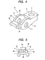
- Fig. 4 is a perspective view of the third intermediate product
- Fig. 5 is a process drawing of manufacturing a valve engaging portion
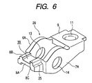
- Fig. 6 is a perspective view of the fourth intermediate product
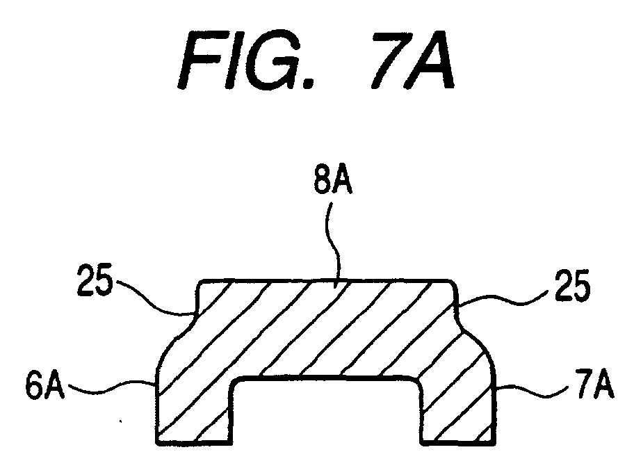
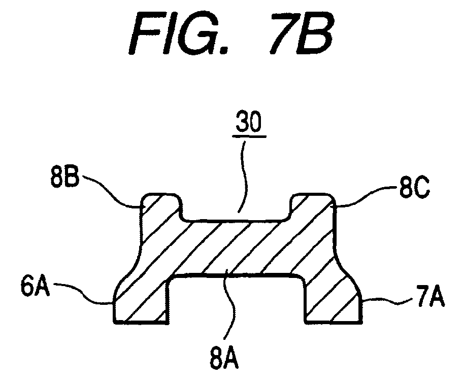
- Fig. 7 is a view showing a change in the shape of the valve engaging portion in the manufacturing process
- Fig. 8 is a perspective view of the fifth intermediate product
- Fig. 9 is an enlarged view showing the continuity of a metal flow in the valve engaging portion.
- this rocker arm 1 is of the end pivot type having the constitution in which the body 4 is tilted by the rotation of the cam 3 with one end side in the longitudinal direction of the rocker arm 1, which is supported by the lash adjuster 2A, serving as a fulcrum. According to the tilting motion of this rocker arm 1, a valve not shown in the drawing is opened and closed.
- This rocker arm 1 includes the body 4 and the roller 5.
- This body 4 includes: a pair of side walls 6, 7 which are opposed to each other in the axial direction of the roller 5; the connecting walls 8, 9 for connecting the side walls 6, 7 with each other, arranged on one end side and the other end side in the longitudinal direction the valve engaging portion 10 arranged on one end side in the longitudinal direction; and the pivot receiving portion 11 arranged on the other end side in the longitudinal direction.
- insertion holes 13, 14 into which the support shaft 12 is inserted.
- the valve engaging portion 10 includes the valve guide walls 28, 29, which are formed by partially deforming the side walls 6, 7, and the connecting wall 8. A metal flow formed between the valve guide walls 28, 29 and the connecting wall 8 in the valve engaging portion 10 is continuous.
- the valve guide walls 28, 29 are used for guiding the valve stem 2B.
- the connecting wall 9 on the other end side in the longitudinal direction has the pivot receiving portion 11 for receiving an upper end portion of the lash adjuster 2.
- the roller 5 is arranged in such a manner that a portion of the roller 5 sticks out from the opening 15 formed in the bottom portion between the two connecting walls 8, 9 in the body 4.
- This roller 5 is pivotally supported by the support shaft 12 via a plurality of needle rollers 5a.
- one metallic sheet (steel sheet) is punched by means for press forming to obtain a metallic sheet member of a predetermined shape, at both side edges of which the arcuate portions 16 are provided.
- the metallic sheet member is punched so as to form the opening 15 at the substantial center. Accordingly, the metallic sheet member is formed into a shape having the predetermined side wall regions 6A, 7A and the predetermined connecting wall regions 8A, 9A.
- a central region of the predetermined connecting wall region 9A on the other end side is subjected to drawing and formed into the hemispherical pivot receiving portion 11. Regions close to the arcuate portions 16 of this metallic sheet member M are punched into the insertion holes 13, 14. In this way, the first intermediate product 17 shown in Fig. 2 is provided.
- Folding is conducted on the first intermediate product 17 at positions shown by the broken lines "a" and "b” in Fig. 2. In this way, the second intermediate product 18 shown in Fig. 3 is provided.
- this second intermediate product 18 When folding has been conducted, this second intermediate product 18 is formed into a substantial U-shape when a view is taken from the front.
- This second intermediate product 18 includes: a pair of side walls 6A, 7A which are arranged being opposed to each other in the axial direction; the predetermined connecting wall region 8A for connecting the predetermined valve guide wall regions 8B, 8C corresponding to one end side of the predetermined side wall regions 6A, 7A; and the predetermined connecting wall region 9A for connecting the other end sides of the predetermined sidewall regions 6A, 7A.
- the predetermined connecting wall region 9A becomes the connecting wall 9 as it is.
- a predetermined metallic die is set so that the intermediate portions of the predetermined side wall regions 6A, 7A in the longitudinal direction of the second intermediate product 18 are held, and portions Corresponding to the lower side of the predetermined valve guide wall regions 8B/ 8C are pressed from both sides toward the inside (in the cross direction) by the first metallic dies 26, 27 (shown in Fig. 6), the cross sections of which are formed into a substantial rectangle.
- the predetermined connecting wall region 8A is compressed and formed in the cross direction. Due to the compressive forming, the step-like side portions 25 are formed in the predetermined valve guide wall regions 8B, 8C. Accordingly, the wall thickness of the predetermined connecting wall region 8A is increased, and the third intermediate product 19 shown in Fig. 4 will be provided. When necessary, softening annealing is conducted on the third intermediate product 19 so as to remove the internal stress.
- the second metallic die 24 for forming a groove which is separated from the first metallic dies 26, 27, is abutted against the intermediate positions on the lower face side of the predetermined valve guide wall regions 8B, 8C and the second metallic die 24 for forming a groove presses the portion of the predetermined connecting wall region 8A, so that a central region on the lower face side of the predetermined connecting wall region 8A is deformed being recessed upward (in the height direction).
- both sides of the recessed portion that is, the predetermined valve guide wall regions 8B, 8C, are made to plastically flow downward so that the height can be increased, and the groove 30 is formed by the predetermined connecting wall region 8A and the predetermined valve guide wall regions 8B, 8C.
- the fourth intermediate product 20 shown in Fig. 6 is provided.
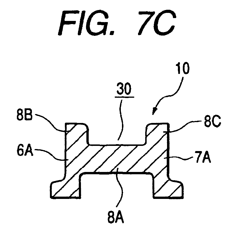
- Figs. 7A to 7C show a change in the cross section of the valve engaging portion 10 in the process of machining.
- the predetermined connecting wall region 8A is gradually moved downward and the depth of the groove 30 is successively increased so that the predetermined connecting wall region 8A can be located at an intermediate portion in the height direction of the predetermined valve guide wall regions 8B, 8C, and the height of the predetermined valve guide wall regions 8B, 8C is gradually increased. In this way, the fifth intermediate product 21 shown in Fig. 8 is obtained.
- the final machining for forming a groove is conducted and a bottom face of the predetermined connecting wall region 8A is formed into a curved face having a predetermined radius of curvature by a pressing punch used for finishing not shown so that the bottom face of the predetermined connecting wall region 8A can be formed into the connecting wall 8.
- the predetermined valve guide wall regions 8B, 8C are made to be the valve guide walls 28, 29.
- the predetermined side wall regions 6A, 7A are made to be the side walls 6, 7. In this way, as shown in Fig. 1, the product having the valve engaging portion 10, the depth of which is sufficiently large, can be obtained as shown in Fig. 1.
- valve engaging portion 10 When the valve engaging portion 10 is machined, while forces given to conduct the machining in the cross direction and the machining for forming a groove are being adjusted, the machining is repeatedly conducted by a plurality of times so that the metal flow 30 between the valve guide walls 28, 29 and the connecting wall 8 can be made to continue. Accordingly, the rigidity of the valve engaging portion 10 can be ensured and the quality of the rocker arm 1 can be stabilized.
- the metal flow continues between both the side walls and the connecting wall. Therefore, the rigidity of the valve engaging portion can be ensured
Landscapes
- Engineering & Computer Science (AREA)
- Mechanical Engineering (AREA)
- General Engineering & Computer Science (AREA)
- Valve-Gear Or Valve Arrangements (AREA)
Abstract
Description
- The present invention relates to a manufacturing method of a rocker arm.
- A conventional rocker arm is constituted in such a manner that a body and a connecting wall used as a valve stem guide portion, are provided separately from each other and the connecting wall is joined to the body by means of laser beam welding.
- In the case of the above joining structure, since a metal flow between the body and the connecting wall is continuous, it is possible to ensure a sufficiently high mechanical strength itself. However, since the body and the connecting wall are formed separately from each other it is necessary to conduct laser beam welding to join the body and the connecting wall. Therefore, they manufacturing cost is raised. Therefore, in order to abolish the process of laser beam welding, a rocker arm is proposed in which the body and the connecting wall are integrated with each other into one body.
- In the rocker arm in which the body and the connecting wall are integrated into one body, the connecting wall is deformed with respect to the body by means of press forming. However, when press forming is conducted, a metal flow between the body and the connecting wall is cut off by a shock caused in the process of press forming, and the mechanical strength of the continuous portion between the body and the connecting wall is lowered.
- In light of the above problem, an object of the present invention is to provide a method of manufacturing a rocker arm by pressing forming in which the metal flow continues between both the side walls and the connecting wall.
- In order to solve the aforesaid object, the invention is characterized by having the following arrangement. Aspect 1. A method of manufacturing a rocker arm for opening and closing a valve, the method comprising the steps of:
- (a) providing a metallic sheet;
- (b) bending the metallic sheet to form a pair of predetermined side wall regions and an predetermined connecting wall region for connecting the pair of predetermined side wall regions;
- (c) first pressing outer sides of the pair of predetermined side wall regions in a connecting, direction in which the predetermined connecting wall region extends, respectively, to plastically flow so that a height of the pair of predetermined side wall regions is gradually increased;
- (d) second pressing the predetermined connecting wall region so as to be recessed in a height direction perpendicular to the connecting direction; and repeating step (c) and (d) plural times, whereby a portions of the pair of predetermined side wall regions are made to be a pair of valve guide walls of a valve engaging portion which extends in the height direction, in which the predetermined connecting wall region is made to be a connecting wall of the valve engaging portion, which connects the pair of valve guide walls with each other at intermediate portion of the pair of valve guide walls in the height direction.
-
- Aspect 2. A rocker arm for opening and closing a valve comprising:
- a body including a valve engaging portion with which the valve is engaged, the valve engaging portion including a pair of valve guide walls opposed to each other and a connecting wall for connecting the valve guide walls with each other at a middle position in the height direction of the valve guide walls, wherein the body is made of one metallic sheet by plastic deformation so that a metal flow continues between both the valve guide walls and the connecting wall.
-
-
- Fig. 1 is a side view showing a state of the use of the rocker arm of the embodiment of the present invention.
- Fig. 2 is a plan view showing a first intermediate product in the case of manufacturing the rocker arm of the embodiment of the present invention.
- Fig. 3 is a perspective view showing a second intermediate product in the case of manufacturing the rocker arm of the embodiment of the present invention.
- Fig. 4 is a perspective view showing a third intermediate product in the case of manufacturing the rocker arm of the embodiment of the present invention.
- Fig. 5 is a process drawing of manufacturing a valve engaging portion of the rocker arm of the embodiment of the present invention.
- Fig. 6 is a perspective view showing a fourth intermediate product in the case of manufacturing the rocker arm of the embodiment of the present invention.
- Figs. 7A and 7C are a view showing a change in the shape of the valve engaging portion in the manufacturing process.
- Fig. 8 is a perspective view showing a fifth intermediate product in the case of manufacturing the rocker arm of the embodiment of the present invention.
- Figs. 9 is an enlarged view showing the continuity of a metal flow in the valve engaging portion.
-
- Referring to the drawings, the rocker arm of the present invention will be explained as follows. Fig. 1 is a side view showing a state of use of the rocker arm of the present invention, Fig. 2 is a plan view showing a first intermediate product in the case of manufacturing the rocker arm, Fig. 3 is a perspective view of the second intermediate product, Fig. 4 is a perspective view of the third intermediate product, Fig. 5 is a process drawing of manufacturing a valve engaging portion, Fig. 6 is a perspective view of the fourth intermediate product, Fig. 7 is a view showing a change in the shape of the valve engaging portion in the manufacturing process, Fig. 8 is a perspective view of the fifth intermediate product, and Fig. 9 is an enlarged view showing the continuity of a metal flow in the valve engaging portion.
- As shown in Fig. 1, this rocker arm 1 is of the end pivot type having the constitution in which the body 4 is tilted by the rotation of the
cam 3 with one end side in the longitudinal direction of the rocker arm 1, which is supported by thelash adjuster 2A, serving as a fulcrum. According to the tilting motion of this rocker arm 1, a valve not shown in the drawing is opened and closed. - This rocker arm 1 includes the body 4 and the
roller 5. This body 4 includes: a pair ofside walls 6, 7 which are opposed to each other in the axial direction of theroller 5; theconnecting walls side walls 6, 7 with each other, arranged on one end side and the other end side in the longitudinal direction thevalve engaging portion 10 arranged on one end side in the longitudinal direction; and thepivot receiving portion 11 arranged on the other end side in the longitudinal direction. In the middle of theside walls 6, 7, there are formedinsertion holes support shaft 12 is inserted. - The
valve engaging portion 10 includes the valve guide walls 28, 29, which are formed by partially deforming theside walls 6, 7, and theconnecting wall 8. A metal flow formed between the valve guide walls 28, 29 and the connectingwall 8 in thevalve engaging portion 10 is continuous. The valve guide walls 28, 29 are used for guiding thevalve stem 2B. The connectingwall 9 on the other end side in the longitudinal direction has thepivot receiving portion 11 for receiving an upper end portion of the lash adjuster 2. - The
roller 5 is arranged in such a manner that a portion of theroller 5 sticks out from the opening 15 formed in the bottom portion between the two connectingwalls roller 5 is pivotally supported by thesupport shaft 12 via a plurality ofneedle rollers 5a. - Next, the method of manufacturing the rocker arm 1 is explained as follows. First of all, as shown in Fig. 2, one metallic sheet (steel sheet) is punched by means for press forming to obtain a metallic sheet member of a predetermined shape, at both side edges of which the
arcuate portions 16 are provided. Next, the metallic sheet member is punched so as to form the opening 15 at the substantial center. Accordingly, the metallic sheet member is formed into a shape having the predeterminedside wall regions wall regions - A central region of the predetermined connecting
wall region 9A on the other end side is subjected to drawing and formed into the hemisphericalpivot receiving portion 11. Regions close to thearcuate portions 16 of this metallic sheet member M are punched into theinsertion holes intermediate product 17 shown in Fig. 2 is provided. - Folding is conducted on the first
intermediate product 17 at positions shown by the broken lines "a" and "b" in Fig. 2. In this way, the secondintermediate product 18 shown in Fig. 3 is provided. - When folding has been conducted, this second
intermediate product 18 is formed into a substantial U-shape when a view is taken from the front. This secondintermediate product 18 includes: a pair ofside walls wall region 8A for connecting the predetermined valveguide wall regions side wall regions wall region 9A for connecting the other end sides of thepredetermined sidewall regions intermediate product 17 is machined into the secondintermediate product 18, the predetermined connectingwall region 9A becomes the connectingwall 9 as it is. - Next, a portion of each of the predetermined
side walls regions intermediate product 18 machined as described above, that is, the predetermined valveguide wall regions wall region 8A are further machined and formed into thevalve inserting portion 10. - A predetermined metallic die is set so that the intermediate portions of the predetermined
side wall regions intermediate product 18 are held, and portions Corresponding to the lower side of the predetermined valveguide wall regions 8B/ 8C are pressed from both sides toward the inside (in the cross direction) by the firstmetallic dies 26, 27 (shown in Fig. 6), the cross sections of which are formed into a substantial rectangle. - Accordingly, the predetermined connecting
wall region 8A is compressed and formed in the cross direction. Due to the compressive forming, the step-like side portions 25 are formed in the predetermined valveguide wall regions wall region 8A is increased, and the thirdintermediate product 19 shown in Fig. 4 will be provided. When necessary, softening annealing is conducted on the thirdintermediate product 19 so as to remove the internal stress. - Next, as shown in Fig. 5, while the predetermined valve guide,
wall regions metallic die 24 for forming a groove, which is separated from the first metallic dies 26, 27, is abutted against the intermediate positions on the lower face side of the predetermined valveguide wall regions metallic die 24 for forming a groove presses the portion of the predetermined connectingwall region 8A, so that a central region on the lower face side of the predetermined connectingwall region 8A is deformed being recessed upward (in the height direction). Accordingly, both sides of the recessed portion, that is, the predetermined valveguide wall regions groove 30 is formed by the predetermined connectingwall region 8A and the predetermined valveguide wall regions intermediate product 20 shown in Fig. 6 is provided. - Successively, while the predetermined valve
guide wall regions wall region 8A is further deformed being recessed upward by the secondmetallic die 24. Figs. 7A to 7C show a change in the cross section of thevalve engaging portion 10 in the process of machining. - When the machining in the cross direction and the machining for forming a groove are alternately repeated by a plurality of times, as shown in Figs. 7A to 7C, the predetermined connecting
wall region 8A is gradually moved downward and the depth of thegroove 30 is successively increased so that the predetermined connectingwall region 8A can be located at an intermediate portion in the height direction of the predetermined valveguide wall regions guide wall regions intermediate product 21 shown in Fig. 8 is obtained. - Finally, after the machining in the cross direction has been conducted so that the step-shaped
side portion 25 can disappear, the final machining for forming a groove is conducted and a bottom face of the predetermined connectingwall region 8A is formed into a curved face having a predetermined radius of curvature by a pressing punch used for finishing not shown so that the bottom face of the predetermined connectingwall region 8A can be formed into the connectingwall 8. The predetermined valveguide wall regions side wall regions side walls 6, 7. In this way, as shown in Fig. 1, the product having thevalve engaging portion 10, the depth of which is sufficiently large, can be obtained as shown in Fig. 1. - As described above, when the machining in the cross direction and the machining for forming a groove are repeatedly conducted by a plurality of times while forces given to the first metallic dies 26, 27 and the second
metallic die 24 are being adjusted, it is possible to make themetal flow 30 formed between the valve guide walls 28, 29 and the connectingwall 8 of thevalve engaging portion 10 continue as shown in Fig. 9. - When the
valve engaging portion 10 is machined, while forces given to conduct the machining in the cross direction and the machining for forming a groove are being adjusted, the machining is repeatedly conducted by a plurality of times so that themetal flow 30 between the valve guide walls 28, 29 and the connectingwall 8 can be made to continue. Accordingly, the rigidity of thevalve engaging portion 10 can be ensured and the quality of the rocker arm 1 can be stabilized. - As can be seen from the above explanations, according to the present invention, the metal flow continues between both the side walls and the connecting wall. Therefore, the rigidity of the valve engaging portion can be ensured
Claims (2)
- A method of manufacturing a rocker arm for opening and closing a valve, the method comprising the steps of:repeating step (c) and (d) plural times, whereby a portions of the pair of predetermined side wall regions are made to be a pair of valve guide walls of a valve engaging portion which extends in the height direction, in which the predetermined connecting wall region is made to be a connecting wall of the valve engaging portion, which connects the pair of valve guide walls with each other at intermediate portion of the pair of valve guide walls in the height direction.(a) providing a metallic sheet;(b) bending the metallic sheet to form a pair of predetermined side wall regions and an predetermined connecting wall region for connecting the pair of predetermined side wall regions;(c) first pressing outer sides of the pair of predetermined side wall regions in a connecting direction in which the predetermined connecting wall region extends, respectively, to plastically flow so that a height of the pair of predetermined side wall regions is gradually increased;(d) second pressing the predetermined connecting wall region so as to be recessed in a height direction perpendicular to the connecting direction; and
- A rocker arm for opening and closing a valve comprising:a body including a valve engaging portion with which the valve is engaged, the valve engaging portion including a pair of valve guide walls opposed to each other and a connecting wall for connecting the valve guide walls with each other at a middle position in the height direction of the valve guide walls,wherein the body is made of one metallic sheet by plastic deformation so that a metal flow continues between both the valve guide walls and the connecting wall.
Applications Claiming Priority (2)
| Application Number | Priority Date | Filing Date | Title |
|---|---|---|---|
| JP2002185577A JP2004025240A (en) | 2002-06-26 | 2002-06-26 | Rocker arm and its production method |
| JP2002185577 | 2002-06-26 |
Publications (1)
| Publication Number | Publication Date |
|---|---|
| EP1375830A1 true EP1375830A1 (en) | 2004-01-02 |
Family
ID=29717605
Family Applications (1)
| Application Number | Title | Priority Date | Filing Date |
|---|---|---|---|
| EP03014393A Ceased EP1375830A1 (en) | 2002-06-26 | 2003-06-26 | Rocker arm and its manufacturing method |
Country Status (4)
| Country | Link |
|---|---|
| US (1) | US7043836B2 (en) |
| EP (1) | EP1375830A1 (en) |
| JP (1) | JP2004025240A (en) |
| KR (1) | KR100638409B1 (en) |
Cited By (4)
| Publication number | Priority date | Publication date | Assignee | Title |
|---|---|---|---|---|
| EP1816319A1 (en) * | 2006-02-02 | 2007-08-08 | OTICS Corporation | Rocker arm and method of manufacturing same |
| EP2088291A1 (en) * | 2008-02-05 | 2009-08-12 | Otics Corporation | Rocker arm |
| EP1870567A4 (en) * | 2005-04-14 | 2009-11-18 | Jtekt Corp | Rocker arm |
| CN101247905B (en) * | 2005-08-22 | 2010-04-07 | 中西金属工业株式会社 | How to make rocker arm |
Families Citing this family (6)
| Publication number | Priority date | Publication date | Assignee | Title |
|---|---|---|---|---|
| EP1660258B1 (en) * | 2003-08-27 | 2007-09-19 | Gen Tek Technologies Marketing, Inc. | A method for forming a cam-engaged rocker arm |
| US8752271B2 (en) * | 2004-07-30 | 2014-06-17 | Acushnet Company | Golf club groove configuration |
| US20060185636A1 (en) * | 2005-02-23 | 2006-08-24 | Gen Tek Technologies Marketing, Inc. | Manufacturing a rocker lever using cold forming and welding |
| JP4235196B2 (en) * | 2005-08-22 | 2009-03-11 | 中西金属工業株式会社 | Method for manufacturing rocker arm |
| DE102006048342A1 (en) * | 2006-10-12 | 2008-04-17 | Schaeffler Kg | cam follower |
| JP6769691B2 (en) * | 2014-12-26 | 2020-10-14 | 株式会社オティックス | Rocker arm manufacturing method |
Citations (8)
| Publication number | Priority date | Publication date | Assignee | Title |
|---|---|---|---|---|
| DE2438227A1 (en) * | 1974-08-08 | 1976-02-26 | Tatra Np | Air-cooled engine valve play control system - has split rocker arm housing head bolted on cylinder head |
| DE4302781A1 (en) * | 1992-02-12 | 1993-08-19 | Neumayer Erich Gmbh Co Kg | Lever to actuate valves in IC engines - has central round passage in pivot direction, and H- shaped sections on either side |
| US5720245A (en) * | 1995-11-13 | 1998-02-24 | Sandco Automotive Limited | Finger follower arm |
| EP0849436A1 (en) * | 1996-12-18 | 1998-06-24 | Sandco Automotive Limited | Finger follower arm |
| DE19700863A1 (en) * | 1997-01-13 | 1998-07-16 | Schaeffler Waelzlager Ohg | Drag lever |
| EP1057980A2 (en) * | 1999-05-31 | 2000-12-06 | Koyo Seiko Co., Ltd. | Rocker arm and method of fabricating rocker arm body |
| JP2001191139A (en) * | 1999-11-02 | 2001-07-17 | Nakanishi Metal Works Co Ltd | Rocker arm and method of manufacturing the same |
| EP1122408A1 (en) * | 1999-08-18 | 2001-08-08 | Koyo Seiko Co., Ltd. | Rocker arm and method of manufacturing rocker arm body |
Family Cites Families (3)
| Publication number | Priority date | Publication date | Assignee | Title |
|---|---|---|---|---|
| JP2879511B2 (en) * | 1993-07-07 | 1999-04-05 | 光洋精工株式会社 | Press-made rocker arm and method of manufacturing the same |
| US6199527B1 (en) * | 1998-03-12 | 2001-03-13 | Nsk Ltd. | Sheet metal rocker arm, manufacturing method thereof, cam follower with said rocker arm, and assembling method thereof |
| DE10018478A1 (en) * | 2000-04-14 | 2001-10-18 | Behr Gmbh & Co | Condenser for an air conditioning system, in particular for an air conditioning system of a motor vehicle |
-
2002
- 2002-06-26 JP JP2002185577A patent/JP2004025240A/en active Pending
-
2003
- 2003-06-25 US US10/602,773 patent/US7043836B2/en not_active Expired - Lifetime
- 2003-06-26 KR KR1020030041808A patent/KR100638409B1/en not_active Expired - Fee Related
- 2003-06-26 EP EP03014393A patent/EP1375830A1/en not_active Ceased
Patent Citations (8)
| Publication number | Priority date | Publication date | Assignee | Title |
|---|---|---|---|---|
| DE2438227A1 (en) * | 1974-08-08 | 1976-02-26 | Tatra Np | Air-cooled engine valve play control system - has split rocker arm housing head bolted on cylinder head |
| DE4302781A1 (en) * | 1992-02-12 | 1993-08-19 | Neumayer Erich Gmbh Co Kg | Lever to actuate valves in IC engines - has central round passage in pivot direction, and H- shaped sections on either side |
| US5720245A (en) * | 1995-11-13 | 1998-02-24 | Sandco Automotive Limited | Finger follower arm |
| EP0849436A1 (en) * | 1996-12-18 | 1998-06-24 | Sandco Automotive Limited | Finger follower arm |
| DE19700863A1 (en) * | 1997-01-13 | 1998-07-16 | Schaeffler Waelzlager Ohg | Drag lever |
| EP1057980A2 (en) * | 1999-05-31 | 2000-12-06 | Koyo Seiko Co., Ltd. | Rocker arm and method of fabricating rocker arm body |
| EP1122408A1 (en) * | 1999-08-18 | 2001-08-08 | Koyo Seiko Co., Ltd. | Rocker arm and method of manufacturing rocker arm body |
| JP2001191139A (en) * | 1999-11-02 | 2001-07-17 | Nakanishi Metal Works Co Ltd | Rocker arm and method of manufacturing the same |
Non-Patent Citations (1)
| Title |
|---|
| PATENT ABSTRACTS OF JAPAN vol. 2000, no. 24 11 May 2001 (2001-05-11) * |
Cited By (7)
| Publication number | Priority date | Publication date | Assignee | Title |
|---|---|---|---|---|
| EP1870567A4 (en) * | 2005-04-14 | 2009-11-18 | Jtekt Corp | Rocker arm |
| US7694659B2 (en) | 2005-04-14 | 2010-04-13 | Jtekt Corporation | Rocker arm |
| CN101247905B (en) * | 2005-08-22 | 2010-04-07 | 中西金属工业株式会社 | How to make rocker arm |
| EP1816319A1 (en) * | 2006-02-02 | 2007-08-08 | OTICS Corporation | Rocker arm and method of manufacturing same |
| US7673605B2 (en) | 2006-02-02 | 2010-03-09 | Otics Corporation | Rocker arm and method of manufacturing same |
| EP2088291A1 (en) * | 2008-02-05 | 2009-08-12 | Otics Corporation | Rocker arm |
| US8191523B2 (en) | 2008-02-05 | 2012-06-05 | Otics Corporation | Rocker arm |
Also Published As
| Publication number | Publication date |
|---|---|
| JP2004025240A (en) | 2004-01-29 |
| KR100638409B1 (en) | 2006-10-24 |
| KR20040002717A (en) | 2004-01-07 |
| US7043836B2 (en) | 2006-05-16 |
| US20040000277A1 (en) | 2004-01-01 |
Similar Documents
| Publication | Publication Date | Title |
|---|---|---|
| US5642693A (en) | Rocker arm and method of manufacturing same | |
| EP1792671B1 (en) | Press-formed workpiece with an increased corner portion thickness and apparatus and method for manufacture thereof | |
| JP4685548B2 (en) | Method for manufacturing rocker arm | |
| EP1450007A1 (en) | Rocker arm | |
| US7043836B2 (en) | Manufacturing method of rocker arm | |
| JP3306478B2 (en) | Pressed rocker arm | |
| EP1375829B1 (en) | Rocker arm and manufacturing method thereof | |
| EP1088606A2 (en) | Structural member having closed sections | |
| EP1122408B1 (en) | Rocker arm and method of manufacturing rocker arm body | |
| CN101248254B (en) | Method for manufacturing rocker arm | |
| JP3693564B2 (en) | Rocker arm and manufacturing method thereof | |
| EP1660258B1 (en) | A method for forming a cam-engaged rocker arm | |
| JPH11270311A (en) | Rocker arm and method of manufacturing the same | |
| JP3497374B2 (en) | Rocker arm and method of manufacturing the same | |
| JP3120068B2 (en) | Rocker arm manufacturing method | |
| JP2011140927A (en) | Rocker arm and method for manufacturing the same | |
| JP4099909B2 (en) | Rocker arm body manufacturing method | |
| JP3857681B2 (en) | Rocker arm | |
| JP4819748B2 (en) | Method for manufacturing rocker arm | |
| JP2019038015A (en) | Press forming method for tubular parts and O-bending mold used therefor | |
| JP4368518B2 (en) | Rocker arm manufacturing method | |
| JP2020163398A (en) | Cylindrical parts and their manufacturing methods | |
| KR200288059Y1 (en) | A processing device for seat rail of automobile | |
| JP2006250044A (en) | Sheet metal rocker arm manufacturing method | |
| US20070197330A1 (en) | Method for producing a rocker pressure member, and stamping apparatusw |
Legal Events
| Date | Code | Title | Description |
|---|---|---|---|
| PUAI | Public reference made under article 153(3) epc to a published international application that has entered the european phase |
Free format text: ORIGINAL CODE: 0009012 |
|
| AK | Designated contracting states |
Kind code of ref document: A1 Designated state(s): AT BE BG CH CY CZ DE DK EE ES FI FR GB GR HU IE IT LI LU MC NL PT RO SE SI SK TR |
|
| AX | Request for extension of the european patent |
Extension state: AL LT LV MK |
|
| 17P | Request for examination filed |
Effective date: 20031215 |
|
| 17Q | First examination report despatched |
Effective date: 20040525 |
|
| AKX | Designation fees paid |
Designated state(s): DE FR GB IT |
|
| RAP1 | Party data changed (applicant data changed or rights of an application transferred) |
Owner name: JTEKT CORPORATION |
|
| STAA | Information on the status of an ep patent application or granted ep patent |
Free format text: STATUS: THE APPLICATION HAS BEEN REFUSED |
|
| 18R | Application refused |
Effective date: 20080713 |