EP1375263B2 - Vehicle occupant protection device - Google Patents
Vehicle occupant protection device Download PDFInfo
- Publication number
- EP1375263B2 EP1375263B2 EP03090171A EP03090171A EP1375263B2 EP 1375263 B2 EP1375263 B2 EP 1375263B2 EP 03090171 A EP03090171 A EP 03090171A EP 03090171 A EP03090171 A EP 03090171A EP 1375263 B2 EP1375263 B2 EP 1375263B2
- Authority
- EP
- European Patent Office
- Prior art keywords
- airbag
- protection device
- occupant protection
- longitudinally extended
- extended element
- Prior art date
- Legal status (The legal status is an assumption and is not a legal conclusion. Google has not performed a legal analysis and makes no representation as to the accuracy of the status listed.)
- Expired - Lifetime
Links
- 238000003466 welding Methods 0.000 claims description 4
- 238000004026 adhesive bonding Methods 0.000 claims description 2
- 239000007789 gas Substances 0.000 description 52
- 238000009958 sewing Methods 0.000 description 3
- 230000001960 triggered effect Effects 0.000 description 3
- 239000004744 fabric Substances 0.000 description 2
- 230000004048 modification Effects 0.000 description 2
- 238000012986 modification Methods 0.000 description 2
- 230000008719 thickening Effects 0.000 description 2
- 230000009471 action Effects 0.000 description 1
- 230000000712 assembly Effects 0.000 description 1
- 238000000429 assembly Methods 0.000 description 1
- 230000008859 change Effects 0.000 description 1
- 238000010276 construction Methods 0.000 description 1
- 238000006073 displacement reaction Methods 0.000 description 1
- 238000003780 insertion Methods 0.000 description 1
- 230000037431 insertion Effects 0.000 description 1
- 239000000463 material Substances 0.000 description 1
- 238000000034 method Methods 0.000 description 1
- 230000007480 spreading Effects 0.000 description 1
Images


Classifications
-
- B—PERFORMING OPERATIONS; TRANSPORTING
- B60—VEHICLES IN GENERAL
- B60R—VEHICLES, VEHICLE FITTINGS, OR VEHICLE PARTS, NOT OTHERWISE PROVIDED FOR
- B60R21/00—Arrangements or fittings on vehicles for protecting or preventing injuries to occupants or pedestrians in case of accidents or other traffic risks
- B60R21/02—Occupant safety arrangements or fittings, e.g. crash pads
- B60R21/16—Inflatable occupant restraints or confinements designed to inflate upon impact or impending impact, e.g. air bags
- B60R21/23—Inflatable members
- B60R21/231—Inflatable members characterised by their shape, construction or spatial configuration
- B60R21/2334—Expansion control features
- B60R21/2338—Tethers
-
- B—PERFORMING OPERATIONS; TRANSPORTING
- B60—VEHICLES IN GENERAL
- B60R—VEHICLES, VEHICLE FITTINGS, OR VEHICLE PARTS, NOT OTHERWISE PROVIDED FOR
- B60R21/00—Arrangements or fittings on vehicles for protecting or preventing injuries to occupants or pedestrians in case of accidents or other traffic risks
- B60R21/02—Occupant safety arrangements or fittings, e.g. crash pads
- B60R21/16—Inflatable occupant restraints or confinements designed to inflate upon impact or impending impact, e.g. air bags
- B60R21/23—Inflatable members
- B60R21/231—Inflatable members characterised by their shape, construction or spatial configuration
- B60R21/232—Curtain-type airbags deploying mainly in a vertical direction from their top edge
-
- B—PERFORMING OPERATIONS; TRANSPORTING
- B60—VEHICLES IN GENERAL
- B60R—VEHICLES, VEHICLE FITTINGS, OR VEHICLE PARTS, NOT OTHERWISE PROVIDED FOR
- B60R21/00—Arrangements or fittings on vehicles for protecting or preventing injuries to occupants or pedestrians in case of accidents or other traffic risks
- B60R21/02—Occupant safety arrangements or fittings, e.g. crash pads
- B60R21/16—Inflatable occupant restraints or confinements designed to inflate upon impact or impending impact, e.g. air bags
- B60R2021/161—Inflatable occupant restraints or confinements designed to inflate upon impact or impending impact, e.g. air bags characterised by additional means for controlling deployment trajectory
-
- B—PERFORMING OPERATIONS; TRANSPORTING
- B60—VEHICLES IN GENERAL
- B60R—VEHICLES, VEHICLE FITTINGS, OR VEHICLE PARTS, NOT OTHERWISE PROVIDED FOR
- B60R21/00—Arrangements or fittings on vehicles for protecting or preventing injuries to occupants or pedestrians in case of accidents or other traffic risks
- B60R21/02—Occupant safety arrangements or fittings, e.g. crash pads
- B60R21/16—Inflatable occupant restraints or confinements designed to inflate upon impact or impending impact, e.g. air bags
- B60R21/23—Inflatable members
- B60R21/231—Inflatable members characterised by their shape, construction or spatial configuration
- B60R21/2334—Expansion control features
- B60R21/2338—Tethers
- B60R2021/23386—External tether means
Definitions
- the invention relates to an occupant protection device for motor vehicle occupants according to the preamble of patent claim 1.
- Such a device is off DE 29 903 778 U1 and DE 10 129 581 A1 and comprises an airbag which is arranged on a motor vehicle body in the region of the lateral roof edge of the motor vehicle and which unfolds during inflation by means of a gas generator down so that it extends in the inflated state like a curtain in front of at least one side window of the motor vehicle the upper edge of the airbag runs along the roof edge of the motor vehicle and the lower edge of the airbag extends approximately at the level of a door sill (eg in the vehicle longitudinal direction). Furthermore, guide means are provided, by means of which the lower edge of the airbag can be guided during inflation along the deployment direction of the airbag down, including the guide means are connected to a portion of the airbag in the region of the lower edge thereof.
- a problem with such occupant protection devices for motor vehicles is to achieve by targeted guidance of the lower edge of the airbag that the lower edge of the airbag is sufficiently braced in the inflated state, to prevent the motor vehicle occupant to be protected in a crash, e.g. when overturning the motor vehicle, can be thrown out through a side window of the motor vehicle.
- the invention is based on the problem to provide an occupant protection device of the type mentioned above, which is characterized by a simple construction by a reliable tension of the lower edge of the inflated airbag.
- the lower edge of the airbag is connected to a section of an elongate element which is movably guided along the direction of deployment of the airbag on the motor vehicle body and which serves to guide the lower edge of the airbag in the deployment direction during inflation of the airbag.
- the elongated element is guided by means of two in the deployment direction of the airbag spaced-apart guide elements, which are each formed in particular as deflecting elements and connected to the vehicle body.
- These two guiding or deflecting elements ensure targeted positioning of the elongate element along the vehicle body even before deployment of the airbag. Because due to their connection with the vehicle body, the two guiding or deflecting elements form a body-side guide device, by means of which the elongated element is already defined prior to deployment of the airbag (ie also in the state in which the airbag is stowed on the roof edge region of the corresponding motor vehicle) is guided.
- the elongate member is guided and tightened so that the associated with the gas bag portion of the elongate member is not deflected transversely to the extension direction of the elongated element during inflation and deployment of the gas bag.
- the lower edge of the airbag can thereby be selectively guided during deployment of the airbag in a position in which a sufficient tension of the lower edge of the airbag is ensured.
- the elongate element does not have to be actively moved by an additional drive in the deployment direction, but the movement of the elongate element in the deployment direction can be caused by the gas bag unfolding during inflation itself.
- the elongate element is guided by means of suitable guide elements such that the lower edge of the gas bag is imposed by cooperation with the elongate element, a deployment in the desired deployment direction.
- the elongate element is to be guided in such a way that a movement of the elongated element along the desired deployment direction of the airbag is triggered by the forces exerted on the elongated element during deployment of the airbag.
- the elongated element is preferably a flexible traction means, e.g. in the form of a rope or a ribbon.
- a backstop may be provided which prevents movement of the elongate element counter to the direction in which it had moved during deployment.
- At least one deflecting element serves to guide the elongate element along the desired deployment direction of the airbag, wherein the backstop is preferably arranged next to one of the deflecting elements.
- the elongate member is formed as a closed (endless) loop, while according to another embodiment, the elongate member is fixed with a free end to the airbag and with the other free end to a part of the vehicle body.
- the two deflection elements can both directly with a part of the vehicle body, such. a holding plate, be connected, so in particular directly to a part of the vehicle body arranged or fixed, or alternatively via another assembly, e.g. in the form of an elastic element to be connected to a part of the vehicle body. It is crucial that none of the two deflecting elements is arranged on the gas bag itself, that is not moved together with the gas bag in the deployment direction during deployment of the airbag. Accordingly, a part of the motor vehicle body is understood to mean any body-fixed bearing parts, in particular in the form of a holding element.
- the movement of the section of the elongate element connected to the gas bag along the desired deployment direction is assisted by a spring element coupled to the elongate element.
- This embodiment is particularly advantageous when the elongated member is fixed in the manner of an open system with one end to the gas bag and with the other end to the vehicle body.
- the spring force also contributes to a defined tightening of the elongated element.
- the portion of the elongate element connected to the lower edge of the airbag is inclined with respect to the main deployment direction of the airbag (which points vertically downwards from the roof edge of the vehicle along the vertical vehicle axis) so that the lower edge of the airbag becomes increasingly unfolding is streamlined.
- the elongate element then serves to reinforce the tightening of the lower edge of the gas bag by imposing an additional movement of the lower edge in the vehicle longitudinal direction downwards from the roof edge downwards for the natural deployment direction of the gas bag, which reinforces the tightening of the lower edge.
- the assemblies used for guiding and / or tightening the elongated element may be arranged at least partially on an already present holding element (holding plate) of the gas generator used for inflating the airbag.
- the lower edge of the airbag is only at one end, in particular at one of a vertical column, e.g. the B-pillar, the vehicle associated end is guided by means of the elongate member, while the other end of the airbag is arranged body-mounted.
- connection between gas bag and elongated element in particular in the form of a rope or a band, can be insoluble, e.g. cohesively, by gluing or welding. Furthermore, a connection can be made by sewing, if on the elongate member, a portion is provided which can be connected to the fabric of the airbag via a seam.
- a detachable connection between the gas bag and the elongated element it may be provided to knot the elongated element with the gas bag using an opening formed on the gas bag.
- a loop of the elongate element can be wrapped around a dart provided on the gas bag.
- a detachable connection between the gas bag and the elongated element can be produced using a clip element, which is connected on one side to the gas bag and on the other hand to the elongated element.
- a tab or pocket can be arranged on the gas bag envelope, with which the elongated element is suitably connected.
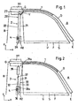
- FIG. 1 shows a view of the side body of a motor vehicle in the region of a front side window F. This is bounded upwards and forwards by the roof edge portion D of the motor vehicle, which - with respect to the vehicle longitudinal axis x - extends forward to the A-pillar of the motor vehicle. To the rear, the front side window F is bounded by the vertical (along the vertical axis of the vehicle z) extending B-pillar and down in the usual way by a door sill.
- an airbag module is arranged in a known manner, which comprises a gas bag 1 extending in the folded state along the entire roof edge region D enclosing the front side window F. This is inflatable by means of a gas generator G, which is attached to a arranged at the upper end of the B-pillar retaining plate H1.
- the front end of the lower edge of the airbag (corresponding to the front end of the tension line S) fixed at the front, lower end E of the roof edge region D set.
- the rear end of the lower edge of the airbag 1 is in contrast connected by means of a connecting element V with a first portion 21 of an elongated element 20 in the form of a closed loop forming rope which forms part of a guide means 2 for guiding the rear end of the lower edge of the airbag during deployment of the gas bag forms.
- the cable 20 is guided by means of two deflecting elements 26, 27 such that a section 21 of the cable 20 extends adjacent to the rear edge of the window pane F and another section 22 of the cable extends on the side of the first section 21 facing away from the window pane F.
- Both sections 21, 22 of the cable 20 extend substantially parallel to the vertical vehicle axis z along the B-pillar B.
- a greater inclination of at least one of the sections 21, 22 of the Rope 20 be advantageous to the vertical axis of the vehicle z, as shown below FIG. 2 will become clear.
- the lower of the two along the vertical axis of the vehicle z spaced deflecting elements 26, 27 is arranged on a holding plate H2 (holding plate), which is arranged on the B-pillar B approximately at the level of the lower pane edge U.
- the other deflecting element 27 is arranged on the holding plate H1, which also serves to receive the gas generator G.
- the deflecting elements may be, for example, rotatably mounted pulleys.
- a backstop 4 is arranged on the lower holding plate H2, which allows a movement of the cable 20 in such a way that the first cable section 21 (along the deployment direction of the airbag 1) moves downward and the second cable section 22 in the opposite direction upwards while a movement of the cable 20 is locked in the reverse direction.
- the airbag 1 is inflated by gases flowing out of the gas generator G and he unfolds from the roof edge portion D down towards the lower edge U of the front side window F.
- the rear end of the lower edge of the airbag 1 which is connected via a connecting element V with the first portion 21 of the cable 20, guided precisely along the path defined by the cable section 21.
- this cable section 21 moves downwards due to the forces acting down upon deployment of the airbag 1 together with the rear end of the lower edge of the airbag 1, ie, the loop 20 forming a loop is rotated clockwise about the deflection elements 26 configured as pulleys. 27 moves.
- first cable section 21 and the second cable section 22 each denote that section of the cable which lies opposite the front side window F or the front side window F. That is to say, the areas of the cable 20 which respectively support the first cable section 21 and the first cable section 21 form second cable section 22, change during a movement of the cable 20 about the deflecting elements 26, 27.
- the lower edge of the airbag 1 is then along the line of tension S between the front lower end E of the roof edge region D, where the front end of the lower edge of the airbag 1 is fixed, and the lower end of the first cable section 21, where the rear end of the lower edge of the airbag 1 is fixed, strained and thereby tightened.
- FIG. 2 illustrated embodiment differs from that in FIG. 1 shown in the training of the guide device 3, which serves to guide the rear end of the lower edge of the airbag 1 along the B-pillar B.
- the guide device 3 comprises an elongate element 30 in the form of a cable, whose one section 31 is guided along the trailing edge of the front side window F and which is fastened with a free end 31 a at the rear end of the lower edge of the airbag 1.
- the first cable section 31 is deflected in such a way that a second cable section 32 extends parallel to the vertical vehicle axle up to the lower free end 37 of a tension spring 38 on the side of the first cable section 31 facing away from the window pane F. , which is fastened at its other end to the upper holding plate H1, which serves to receive the gas generator G.
- the cable 30 is deflected again, so that from there a further cable section 33 extends to the lower holding plate H2, at which that cable section 33 is fixed with its free end 33a.
- FIG. 2 shown embodiment Another special feature of in FIG. 2 shown embodiment is that the first cable section 31 is not exactly parallel to the vertical vehicle axis z or to the rear edge of the window F, but rather is slightly inclined backwards. As a result, the lower edge of the airbag 1 during deployment of the airbag is additionally tightened, as will be explained below.
- the gas bag 1 is filled by means of the gas generator G with gas, wherein the gas bag 1 unfolds in the direction of the lower edge U of the front side window F.
- the tension spring 38 connected to the one free end 31a of the first cable section 31 rear end of the lower edge of the airbag 1 in the direction of the lower deflecting element 36 of the guide device 3 moves. Since this movement does not take place exactly parallel to the vertical vehicle axis z, but rather additionally has a component towards the rear (along the vehicle longitudinal direction x, directed towards the rear of the corresponding vehicle), the lower edge of the airbag 1 becomes the lower edge due to the associated displacement of the rear end in addition tightened and thereby stretched.
- a backstop 4 which is arranged on the lower plate H2, a return of the cable 30 after deployment of the airbag 1, so that the lower edge of the airbag 1 permanently along the tension line S between the front lower end E of the roof edge region D and the lower deflecting element 36 is clamped.
- FIG. 2 illustrated embodiments of an airbag assembly is in each case the leadership of the airbag (in the region of its rear lower end) according to the "flagpole principle" what the each serving as a tensioning flexible traction means in the form of a cable 20, 30 by means of two deflection elements 26, 27 and 36, 37 out is, in the deployment direction of the airbag 1 (ie, along the vertical axis of the vehicle z) spaced from each other with a portion H1, H2 of the vehicle body are connected.
- the respective cable 20, 30 is already guided before unfolding of the airbag 1 (ie in the initial state before triggering of the gas generator) between the respective deflection elements 26, 27 and 36, 37. After triggering the airbag module and during deployment of the airbag 1, only one other section of the cable 20 or 30 then moves into the area between the two deflecting elements 26, 27 or 36, 37, wherein the rear lower end of the airbag 1 is taken down.
- a deflecting element cf., the upper deflecting element 37 in the exemplary embodiment according to FIG. 2
- another assembly eg, a tension spring 38
- the gas bag 1 here preferably consists of one or more parts of fabric which are sewn together to form a closed working space of the airbag. Trained as a rope or band elongate member may for example consist of plastic or woven material.
- FIGS. 3 to 5b illustrated connections between a gas bag and an elongated element in the form of a rope are particularly suitable for such cases in which the cable 20 forms a closed loop of rope.
- This closed loop is by connecting, z. B. welding, the two free ends of a rope.
- a thickening 201 is formed, which is welded to a portion of the airbag 1.
- FIG. 4 is at a portion of the rope 20 a broadening, z. B. in the form of a flag 202, which is sewn by means of a seam 101 with a portion of the airbag 1.
- FIG. 5a is attached to a portion of the airbag cover 1 by means of a seam 51, a portion 50 of a clip element 5, which surrounds the cable 20 with a resiliently shaped end portion 55 into which the cable 20 through an opening 56 by spreading the resilient portion 55 is inserted.
- FIG. 5b an arrangement is shown in which the gas bag 1 has a passage opening 102, in which a provided with an insertion 61 section 60 of a Klips institutes 6 is threaded, which surrounds the cable 20 with another section 65.
- a bracket 204 is provided on the cable 20, to which the two free ends 210, 220 are attached to form a cable loop.
- a section 203 of the cable 20 is additionally looped around a dart 103 of the airbag 1, so that the cable 20 is connected thereto with the gas bag 1.
- the two free ends 210, 220 of an elongate element 20 designed as a band are connected at a fastening point by means of a seam 104 to the casing of an airbag 1.
- the two free ends 210, 220 of a cable 20 are each provided with a thickening 211 or 221, by means of which they are held in a form-fitting manner in corresponding bulges 71, 72 of the base body 70 of a clip element 7.
- the clip element 7 has two clip sections 73, 74 lying opposite one another, each of which engages around an edge of a pocket 105 in a form-fitting manner, which is fastened to the envelope of an airbag 1 by means of a seam 106.
- FIG. 8b is also attached to the shell of a gas bag 1 by means of a seam 106, a pocket 105 which is penetrated by an end portion 210 of the cable 20, while the other end portion 220 of the cable 20 is guided externally on the pocket 105.
- the two end portions 210, 220 of the cable 20 are connected to each other at two attachment points 8a, 8b spaced apart along the extension direction of the cable 20 on both sides of the pocket 105, so that the pocket 105 between the two end portions 210, 220 of the cable 20 and the associated fasteners 8a, 8b is received positively.
- an integrally formed on the shell of the airbag 1 pocket 107 is penetrated by a strand 20a of a rope 20 formed from two strands 20a, 20b, so that the pocket 107 is positively received between the two strands 20a, 20b.
Landscapes
- Engineering & Computer Science (AREA)
- Mechanical Engineering (AREA)
- Air Bags (AREA)
Description
Die Erfindung betrifft eine Insassenschutzeinrichtung für Kraftfahrzeuginsassen nach dem Oberbegriff des Patentanspruchs 1.The invention relates to an occupant protection device for motor vehicle occupants according to the preamble of
Eine derartige Einrichtung ist aus
Ein Problem bei derartigen Insassenschutzeinrichtungen für Kraftfahrzeuge liegt darin, durch eine gezielte Führung der Unterkante des Gassackes zu erreichen, dass die Unterkante des Gassackes im aufgeblasenen Zustand hinreichend verspannt ist, um zu verhindern, dass der zu schützende Kraftfahrzeuginsasse in einem Crash-Fall, z.B. bei einem Überschlagen des Kraftfahrzeugs, durch eine Seitenscheibe des Kraftfahrzeugs hinausgeschleudert werden kann.A problem with such occupant protection devices for motor vehicles is to achieve by targeted guidance of the lower edge of the airbag that the lower edge of the airbag is sufficiently braced in the inflated state, to prevent the motor vehicle occupant to be protected in a crash, e.g. when overturning the motor vehicle, can be thrown out through a side window of the motor vehicle.
Der Erfindung liegt das Problem zugrunde, eine Insassenschutzeinrichtung der eingangs genannten Art zu schaffen, die sich bei einfachem Aufbau durch eine zuverlässige Verspannung der Unterkante des aufgeblasenen Gassackes auszeichnet.The invention is based on the problem to provide an occupant protection device of the type mentioned above, which is characterized by a simple construction by a reliable tension of the lower edge of the inflated airbag.
Dieses Problem wird erfindungsgemäß durch die Schaffung einer Insassenschutzeinrichtung mit den Merkmalen des Patentanspruchs 1 gelöst.This problem is solved according to the invention by the provision of an occupant protection device having the features of
Danach ist die Unterkante des Gassackes mit einem entlang der Entfaltungsrichtung des Gassackes an der Kraftfahrzeugkarosserie bewegbar geführten (und z.B. in dieser Richtung erstreckten) Abschnitt eines länglichen Elementes verbunden, das zur Führung der Unterkante des Gassackes in Entfaltungsrichtung beim Aufblasen des Gassackes dient.Thereafter, the lower edge of the airbag is connected to a section of an elongate element which is movably guided along the direction of deployment of the airbag on the motor vehicle body and which serves to guide the lower edge of the airbag in the deployment direction during inflation of the airbag.
Dabei wird das längserstreckte Element mittels zweier in Entfaltungsrichtung des Gassackes voneinander beabstandeter Führungselemente geführt, die insbesondere jeweils als Umlenkelemente ausgebildet und mit der Fahrzeugkarosserie verbunden sind. Diese beiden Führungs- bzw. Umlenkelemente sorgen für eine gezielte Positionierung des längserstreckten Elementes entlang der Fahrzeugkarosserie bereits vor dem Entfalten des Gassackes. Denn aufgrund ihrer Verbindung mit der Fahrzeugkarosserie bilden die beiden Führungs- bzw. Umlenkelemente eine karosserieseitige Führungseinrichtung, mittels der das längserstreckte Element bereits vor dem Entfalten des Gassackes (also auch in dem Zustand, in dem der Gassack am Dachkantenbereich des entsprechenden Kraftfahrzeugs verstaut ist) definiert geführt ist. Bei einem Aufblasen des Gassackes in einem Crash-Fall erfolgt dann nach dem sogenannten Fahnenmastprinzip" eine Bewegung des längserstreckten Elementes lediglich in der Weise, dass ein anderer Abschnitt des längserstreckten Elementes in den Bereich zwischen den beiden Führungs- bzw. Umlenkelementen gerät und der vor dem Aufblasen des Gassackes zwischen den beiden Umlenkelementen befindliche Abschnitt des längserstreckten Elementes aus diesem Bereich herausgeführt wird. Hierdurch wird eine definierte und zuverlässige Führung des Gassackes mittels des längserstreckten Elementes im Bereich zwischen den beiden Umlenkelementen erreicht, nämlich eine gezielte Führung entlang der Fahrzeugkarosserie.In this case, the elongated element is guided by means of two in the deployment direction of the airbag spaced-apart guide elements, which are each formed in particular as deflecting elements and connected to the vehicle body. These two guiding or deflecting elements ensure targeted positioning of the elongate element along the vehicle body even before deployment of the airbag. Because due to their connection with the vehicle body, the two guiding or deflecting elements form a body-side guide device, by means of which the elongated element is already defined prior to deployment of the airbag (ie also in the state in which the airbag is stowed on the roof edge region of the corresponding motor vehicle) is guided. When inflating the airbag in a crash case then takes place according to the so-called flagpole principle "movement of the elongated element only in such a way that another portion of the elongated element device in the area between the two guide and deflecting elements and before In this way, a defined and reliable guidance of the gas bag by means of the elongated element in the area between the two deflecting elements is achieved, namely targeted guidance along the vehicle body.
Um eine möglichst starke Straffung der Unterkante des Gassackes zu erreichen, wird das längserstreckte Element derart geführt und gestrafft, dass der mit dem Gassack verbundene Abschnitt des längserstreckten Elementes beim Aufblasen und Entfalten des Gassackes nicht quer zur Erstreckungsrichtung des längserstreckten Elementes ausgelenkt wird.In order to achieve the greatest possible tightening of the lower edge of the gas bag, the elongate member is guided and tightened so that the associated with the gas bag portion of the elongate member is not deflected transversely to the extension direction of the elongated element during inflation and deployment of the gas bag.
Die Unterkante des Gassackes kann hierdurch beim Entfalten des Gassackes gezielt in eine Position geführt werden, in der eine hinreichende Verspannung der Unterkante des Gassackes gewährleistet ist. Hierzu muss das längserstreckte Element nicht aktiv durch einen zusätzlichen Antrieb in Entfaltungsrichtung bewegt werden, sondern die Bewegung des längserstreckten Elementes in Entfaltungsrichtung kann durch den sich beim Aufblasen entfaltenden Gassack selbst hervorgerufen werden. Entscheidend ist allein, dass das längserstreckte Element mittels geeigneter Führungselemente derart geführt ist, dass der Unterkante des Gassackes durch Zusammenwirken mit dem längserstreckten Element eine Entfaltung in der gewünschten Entfaltungsrichtung aufgezwungen wird. Mit anderen Worten ausgedrückt, ist das längserstreckte Element derart zu führen, dass durch die beim Entfalten des Gassackes auf das längserstreckte Element ausgeübten Kräfte eine Bewegung des längserstreckten Elementes entlang der gewünschten Entfaltungsrichtung des Gassackes ausgelöst wird.The lower edge of the airbag can thereby be selectively guided during deployment of the airbag in a position in which a sufficient tension of the lower edge of the airbag is ensured. For this purpose, the elongate element does not have to be actively moved by an additional drive in the deployment direction, but the movement of the elongate element in the deployment direction can be caused by the gas bag unfolding during inflation itself. The only decisive factor is that the elongate element is guided by means of suitable guide elements such that the lower edge of the gas bag is imposed by cooperation with the elongate element, a deployment in the desired deployment direction. In other words, the elongate element is to be guided in such a way that a movement of the elongated element along the desired deployment direction of the airbag is triggered by the forces exerted on the elongated element during deployment of the airbag.
Hierdurch wird mit einfachen Mitteln eine gezielte Entfaltung des Gassackes, insbesondere der Unterkante des Gassackes, in eine Position ermöglicht, in der die Unterkante des Gassackes eine hinreichende Spannung aufweist. Bei dem längserstreckten Element handelt es sich vorzugsweise um ein flexibles Zugmittel, z.B. in Form eines Seiles oder eines Bandes.In this way, by simple means, a targeted deployment of the airbag, in particular the lower edge of the airbag, is made possible in a position in which the lower edge of the airbag has a sufficient tension. The elongated element is preferably a flexible traction means, e.g. in the form of a rope or a ribbon.
Um die beim Entfalten des Gassackes mittels des Führungselementes festgelegte Position der Unterkante des Gassackes aufrechtzuerhalten, kann eine Rücklaufsperre vorgesehen sein, die eine Bewegung des längserstreckten Elementes entgegen der Richtung, in der sich dieses beim Entfalten bewegt hatte, verhindert.In order to maintain the fixed position of the lower edge of the airbag during deployment of the airbag by means of the guide element, a backstop may be provided which prevents movement of the elongate element counter to the direction in which it had moved during deployment.
Zur Führung des längserstreckten Elementes entlang der gewünschten Entfaltungsrichtung des Gassackes dient mindestens ein Umlenkelement, wobei die Rücklaufsperre vorzugsweise neben einem der Umlenkelemente angeordnet ist.At least one deflecting element serves to guide the elongate element along the desired deployment direction of the airbag, wherein the backstop is preferably arranged next to one of the deflecting elements.
Nach einer Ausführungsform der Erfindung ist das längserstreckte Element als eine geschlossene (endlose) Schlaufe ausgebildet, während nach einer anderen Ausführungsform das längserstreckte Element mit einem freien Ende am Gassack und mit dem anderen freien Ende an einem Teil der Kraftfahrzeugkarosserie festgelegt ist.According to one embodiment of the invention, the elongate member is formed as a closed (endless) loop, while according to another embodiment, the elongate member is fixed with a free end to the airbag and with the other free end to a part of the vehicle body.
Die beiden Umlenkelemente können dabei sowohl unmittelbar mit einem Teil der Fahrzeugkarosserie, wie z.B. einer Halteplatte, verbunden sein, also insbesondere direkt an einem Teil der Fahrzeugkarosserie angeordnet oder befestigt sein, oder alternativ über eine weitere Baugruppe, z.B. in Form eines elastischen Elementes, mit einem Teil der Fahrzeugkarosserie verbunden sein. Entscheidend ist, dass keines der beiden Umlenkelemente am Gassack selbst angeordnet ist, also beim Entfalten des Gassackes nicht gemeinsam mit dem Gassack in Entfaltungsrichtung bewegt wird. Dementsprechend werden unter einem Teil der Kraftfahrzeugkarosserie beliebige karosseriefestem tragende Teile, insbesondere in Form eines Halteelementes, verstanden.The two deflection elements can both directly with a part of the vehicle body, such. a holding plate, be connected, so in particular directly to a part of the vehicle body arranged or fixed, or alternatively via another assembly, e.g. in the form of an elastic element to be connected to a part of the vehicle body. It is crucial that none of the two deflecting elements is arranged on the gas bag itself, that is not moved together with the gas bag in the deployment direction during deployment of the airbag. Accordingly, a part of the motor vehicle body is understood to mean any body-fixed bearing parts, in particular in the form of a holding element.
Ferner kann vorgesehen sein, dass die Bewegung des mit dem Gassack verbundenen Abschnittes des längserstreckten Elementes entlang der gewünschten Entfaltungsrichtung durch ein mit dem längserstreckten Element gekoppeltes Federelement unterstützt wird. Diese Ausführungsform ist insbesondere dann vorteilhaft, wenn das längserstreckte Element nach Art eines offenen Systems mit einem Ende am Gassack und mit dem anderen Ende an der Kraftfahrzeugkarosserie fixiert ist. Die Federkraft trägt auch zu einer definierten Straffung des längserstreckten Elementes bei.Furthermore, it can be provided that the movement of the section of the elongate element connected to the gas bag along the desired deployment direction is assisted by a spring element coupled to the elongate element. This embodiment is particularly advantageous when the elongated member is fixed in the manner of an open system with one end to the gas bag and with the other end to the vehicle body. The spring force also contributes to a defined tightening of the elongated element.
Gemäß einer Weiterbildung der Erfindung ist der mit der Unterkante des Gassackes verbundene Abschnitt des längserstreckten Elementes derart geneigt bezüglich der Hauptentfaltungsrichtung des Gassackes (die von der Dachkante des Fahrzeugs entlang der vertikalen Fahrzeugachse senkrecht nach unten weist) geführt, dass die Unterkante des Gassackes beim Entfalten zunehmend gestrafft wird. Das längserstreckte Element dient dann also einer Verstärkung der Straffung der Unterkante des Gassackes, indem der natürlichen Entfaltungsrichtung des Gassackes von der Dachkante her nach unten eine zusätzliche Bewegung der Unterkante in Fahrzeuglängsrichtung aufgezwungen wird, die die Straffung der Unterkante verstärkt.According to one embodiment of the invention, the portion of the elongate element connected to the lower edge of the airbag is inclined with respect to the main deployment direction of the airbag (which points vertically downwards from the roof edge of the vehicle along the vertical vehicle axis) so that the lower edge of the airbag becomes increasingly unfolding is streamlined. The elongate element then serves to reinforce the tightening of the lower edge of the gas bag by imposing an additional movement of the lower edge in the vehicle longitudinal direction downwards from the roof edge downwards for the natural deployment direction of the gas bag, which reinforces the tightening of the lower edge.
Die zur Führung und/oder Straffung des längserstreckten Elementes dienenden Baugruppen können zumindest teilweise an einem ohnehin vorhandenen Halteelement (Halteblech) des zum Aufblasen des Gassackes verwendeten Gasgenerators angeordnet sein.The assemblies used for guiding and / or tightening the elongated element may be arranged at least partially on an already present holding element (holding plate) of the gas generator used for inflating the airbag.
In einer bevorzugten Ausführungsform der Erfindung ist vorgesehen, dass die Unterkante des Gassackes lediglich an einem Ende, insbesondere an einem einer vertikalen Säule, z.B. der B-Säule, des Fahrzeugs zugeordneten Ende mittels des längserstreckten Elementes geführt ist, während das andere Ende des Gassackes karosseriefest angeordnet ist.In a preferred embodiment of the invention it is provided that the lower edge of the airbag is only at one end, in particular at one of a vertical column, e.g. the B-pillar, the vehicle associated end is guided by means of the elongate member, while the other end of the airbag is arranged body-mounted.
Zur Verbindung des Gassackes mit dem längserstreckten Element können unterschiedliche Befestigungsmethoden verwendet werden.To connect the gas bag with the elongated element different attachment methods can be used.
Die Verbindung zwischen Gassack und längserstrecktem Element, insbesondere in Form eines Seiles oder Bandes, kann unlösbar, z.B. stoffschlüssig, durch Kleben oder Schweißen, erfolgen. Ferner kann eine Verbindung durch Nähen erfolgen, wenn an dem längserstreckten Element ein Abschnitt vorgesehen ist, der sich mit dem Gewebe des Gassackes über eine Naht verbinden lässt.The connection between gas bag and elongated element, in particular in the form of a rope or a band, can be insoluble, e.g. cohesively, by gluing or welding. Furthermore, a connection can be made by sewing, if on the elongate member, a portion is provided which can be connected to the fabric of the airbag via a seam.
Für eine lösbare Verbindung zwischen Gassack und längserstrecktem Element kann vorgesehen sein, unter Verwendung einer am Gassack gebildeten Öffnung das längserstreckte Element mit dem Gassack zu verknoten. In einer anderen Variante kann eine Schlaufe des längserstreckten Elementes um einen an dem Gassack vorgesehenen Abnäher herumgelegt werden. Oder es kann eine lösbare Verbindung zwischen Gassack und längserstrecktem Element unter Verwendung eines Klipselementes hergestellt werden, das einerseits mit dem Gassack und andererseits mit dem längserstreckten Element verbunden ist. In einer weiteren Ausführungsform kann an der Gassackhülle eine Lasche oder Tasche angeordnet sein, mit der das längserstreckte Element in geeigneter verbunden wird.For a detachable connection between the gas bag and the elongated element, it may be provided to knot the elongated element with the gas bag using an opening formed on the gas bag. In another variant, a loop of the elongate element can be wrapped around a dart provided on the gas bag. Or a detachable connection between the gas bag and the elongated element can be produced using a clip element, which is connected on one side to the gas bag and on the other hand to the elongated element. In a further embodiment, a tab or pocket can be arranged on the gas bag envelope, with which the elongated element is suitably connected.
Weitere Merkmale und Vorteile der Erfindung werden bei der nachfolgenden Beschreibung von Ausführungsbeispielen anhand der Figuren deutlich werden.Further features and advantages of the invention will become apparent in the following description of exemplary embodiments with reference to the figures.
Es zeigen:
Figur 1- eine Ansicht der seitlichen Karosserie eines Kraftfahrzeugs im Bereich eines vorderen Seitenfensters, mit einer Führungseinrichtung zur Führung eines im Dachkantenbereich angeordneten Gassackes beim Entfalten;
Figur 2- eine Abwandlung des Ausführungsbeispiels aus
Figur 1 Figur 3- eine schematische Darstellung betreffend die Verbindung eines längserstreckten Elementes der Führungseinrichtung aus den
Figuren 1 und 2 Figur 4- eine schematische Darstellung einer Verbindung zwischen Gassack und längserstrecktem Element durch Nähen;
- Figuren 5a und 5b
- schematische Darstellungen für eine Verbindung zwischen Gassack und längserstrecktem Element durch einen Klipp;
- Figur 6
- eine schematische Darstellung einer Verbindung zwischen Gassack und längserstrecktem Element mittels einer Schlaufe des längserstreckten Elementes, die einen Abnäher des Gassackes umschlingt;
Figur 7- eine schematische Darstellung der Verbindung zwischen Gassack und längserstrecktem Element durch Vernähen beider Enden des längserstreckten Elementes am Gassack;
Figuren 8a und 8b- zwei Beispiele einer Verbindung zwischen Gassack und längserstrecktem Element unter Verwendung einer am Gassack vorgesehenen Tasche;
- Figur 9
- eine Abwandlung der Ausführungsbeispiele aus den
Figuren 8a und 8b
- FIG. 1
- a view of the side body of a motor vehicle in the region of a front side window, with a guide means for guiding an airbag arranged in the roof edge region during deployment;
- FIG. 2
- a modification of the embodiment
FIG. 1 , however, not solved by the invention; - FIG. 3
- a schematic representation relating to the connection of an elongated element of the guide means of the
Figures 1 and 2 with the gas bag by welding; - FIG. 4
- a schematic representation of a connection between the gas bag and elongate member by sewing;
- FIGS. 5a and 5b
- schematic representations for a connection between the gas bag and elongate member by a clip;
- FIG. 6
- a schematic representation of a connection between the gas bag and elongate member by means of a loop of the elongate member which wraps around a dart of the airbag;
- FIG. 7
- a schematic representation of the connection between the gas bag and elongate member by sewing both ends of the elongate member to the gas bag;
- FIGS. 8a and 8b
- two examples of a connection between gas bag and elongate member using a provided on the gas bag bag;
- FIG. 9
- a modification of the embodiments of the
FIGS. 8a and 8b ,
Am Dachkantenbereich D der Fahrzeugkarosserie ist in bekannter Weise ein Airbagmodul angeordnet, das einen sich im gefalteten Zustand entlang des gesamten, die vordere Seitenscheibe F einfassenden Dachkantenbereiches D erstreckenden Gassack 1 umfasst. Dieser ist mittels eines Gasgenerators G aufblasbar, der an einem am oberen Ende der B-Säule angeordneten Halteblech H1 befestigt ist.At the roof edge region D of the vehicle body, an airbag module is arranged in a known manner, which comprises a
Beim Aufblasen des Gassackes 1 mittels des Gasgenerators G entfaltet sich dieser nach unten in Rechtung auf die Unterkante U der vorderen Seitenscheibe F und bildet hierdurch einen Vorhang vor der Seitenscheibe F, der als Kopfschutz für einen Fahrzeuginsassen dienen und außerdem das Herausschleudern eines Fahrzeuginsassen durch die seitliche Fensterscheibe F verhindern soll. Hierzu ist von Bedeutung, dass die Unterkannte des entfalteten Gassackes entlang einer Spannungslinie S gespannt ist, die vom vorderen Ende E des Dachkantenbereiches D in Fahrzeuglängsrichtung zu der B-Säule B verläuft.When inflating the
Bei dem in
Das Seil 20 ist mittels zweier Umlenkelemente 26, 27 derart geführt, dass ein Abschnitt 21 des Seiles 20 zu der hinteren Kante der Fensterscheibe F benachbart verläuft und ein anderer Abschnitt 22 des Seiles sich auf der der Fensterscheibe F abgewandten Seite des ersten Abschnittes 21 erstreckt. Beide Abschnitte 21, 22 des Seiles 20 verlaufen im Wesentlichen parallel zur vertikalen Fahrzeugachse z entlang der B-Säule B. Für eine stärkere Straffung der Unterkante des Gassackes 1 entlang der Spannungslinie S kann jedoch auch eine stärkere Neigung mindestens eines des Abschnitte 21, 22 des Seiles 20 zur vertikalen Fahrzeugachse z vorteilhaft sein, wie weiter unten anhand
Das untere der beiden entlang der vertikalen Fahrzeugachse z voneinander beabstandeten Umlenkelemente 26, 27 ist an einer Halteplatte H2 (Halteblech) angeordnet, die an der B-Säule B in etwa auf der Höhe der unteren Scheibenkante U angeordnet ist. Das andere Umlenkelement 27 ist an der Halteplatte H1 angeordnet, die auch zur Aufnahme des Gasgenerators G dient. Bei den Umlenkelementen kann es sich beispielsweise um drehbar gelagerte Seilrollen handeln.The lower of the two along the vertical axis of the vehicle z spaced deflecting
Ferner ist auf der unteren Halteplatte H2 eine Rücklaufsperre 4 angeordnet, die eine Bewegung des Seiles 20 in der Weise zulässt, dass sich der erste Seilabschnitt 21 (entlang der Entfaltungsrichtung des Gassackes 1) nach unten und der zweite Seilabschnitt 22 in entgegengesetzter Richtung nach oben bewegt, während eine Bewegung des Seiles 20 in umgekehrter Richtung gesperrt ist.Further, a
Wird in einem Crash-Fall mittels eines Sensors die in
Nach dem vollständigen Entfalten und Aufblasen des Gassackes 1 befindet sich das hintere Ende von dessen Unterkante im Bereich des unteren Umlenkelementes 26, wobei das hintere Ende der Unterkante zu diesem Punkt durch eine Bewegung des ersten Seilabschnittes 21 nach unten gelangt. (Der erste Seilabschnitt 21 und der zweite Seilabschnitt 22 bezeichnen jeweils denjenigen Abschnitt des Seiles, der der vorderen Seitenscheibe F benachbart bzw. der vorderen Seitenscheibe F abgewandt liegt. D. h., die Bereiche des Seiles 20, die jeweils den ersten Seilabschnitt 21 bzw. zweiten Seilabschnitt 22 bilden, ändern sich bei einer Bewegung des Seiles 20 um die Umlenkelemente 26, 27.)After the complete unfolding and inflation of the
Die Unterkante des Gassackes 1 ist dann entlang der Spannungslinie S zwischen dem vorderen unteren Ende E des Dachkantenbereiches D, wo das vordere Ende der Unterkante des Gassackes 1 fixiert ist, und dem unteren Ende des ersten Seilabschnittes 21, wo das hintere Ende der Unterkante des Gassackes 1 fixiert ist, verspannt und hierdurch gestrafft.The lower edge of the
Die in
Eine weitere Besonderheit des in
Wird in einem Crash-Fall die in
Besonders vorteilhaft bei den in
Durch diese definierte Führung des jeweiligen Seiles 20, 30 nach dem Fahnenmastprinzip wird eine besonders zuverlässige Bewegung der hinteren unteren Kante des Gassackes 1 beim Entfalten sichergestellt.By this defined guidance of the
Dabei kann durchaus ein Umlenkelement (vgl. das obere Umlenkelement 37 bei dem Ausführungsbeispiel gemäß
Anhand der
Die in den
Bei dem Ausführungsbeispiel gemäß
Bei dem Ausführungsbeispiel gemäß
Gemäß
In
Nach
Bei dem Ausführungsbeispiel gemäß
Bei dem in
In
Bei dem Ausführungsbeispiel gemäß
Claims (21)
- Occupant protection device for motor vehicle occupants, with an airbag which is to be arranged on a motor vehicle body in the region of the lateral roof edge of the motor vehicle and which is deployed downwards from the roof edge during inflation for the protection of a vehicle occupant, so that, in the inflated state, it extends in front of at least one side window of the motor vehicle, the top edge of the airbag running along the roof edge, and the lower edge of the airbag running below the roof edge, and with guide means by which the lower edge of the airbag is guided in the direction of deployment during inflation, the lower edge of the airbag (1) being connected to a portion (21, 31) of a longitudinally extended element (20, 30), the said portion being guided movably on the motor vehicle body in the direction of deployment of the airbag (1), the longitudinally extended element (20, 30) being guided by means of two deflection elements (26, 27; 36, 37) which are spaced apart from one another along the direction of deployment (z) of the airbag (1) and are in each case connected to a body-fixed part (H1, H2), and the movement of the longitudinally extended element (20,30) in the direction of deployment being brought about by the airbag (1) as it is deployed and the longitudinally extended element (20, 30) being guided in a defined manner by means of the deflection elements (26, 27; 36, 37) even before the deployment of the airbag (1), characterized in that the longitudinally extended element (20, 30) is guided and/or tautened in such a way that no appreciable deflection of the longitudinally extended element (20, 30) transversely to its direction of extent takes place during the inflation and deployment of the airbag (1).
- Occupant protection device according to Claim 1, characterized in that the longitudinally extended element (20, 30) is formed by a flexible traction means.
- Occupant protection device according to Claim 1 or 2, characterized in that the longitudinally extended element (20, 30) is formed by a cable or a band.
- Occupant protection device according to one of the preceding claims, characterized in that a run-back stop (4) is provided, by means of which a movement of the longitudinally extended element (20, 30) opposite to the direction in which the longitudinally extended element (20, 30) has moved during the deployment of the airbag is prevented.
- Occupant protection device according to Claim 4, characterized in that the run-back stop (4) is arranged next to a deflection element (26, 36).
- Occupant protection device according to one of the preceding claims, characterized in that the longitudinally extended element (20) is designed as a closed loop.
- Occupant protection device according to one of Claims 1 to 5, characterized in that the longitudinally extended element (30) is connected with one end (31a) to the airbag (1) and with the other end (33a) to a body-fixed part (H2).
- Occupant protection device according to one of the preceding claims, characterized in that at least one deflection element (26, 27; 36) is connected directly to a body-fixed part (H1, H2).
- Occupant protection device according to one of the preceding claims, characterized in that at least one deflection element (37) is connected to a body-fixed part (H1) via a further subassembly (38).
- Occupant protection device according to one of the preceding claims, characterized in that a movement of the portion (31) of the longitudinally extended element (30) in the direction of deployment of the airbag (1) is assisted by spring force.
- Occupant protection device according to Claim 10, characterized in that the longitudinally extended element (30) is tautened by means of the spring force.
- Occupant protection device according to one of the preceding claims, characterized in that the portion (31) of the longitudinally extended element (30) is guided at an inclination with respect to the main direction of deployment (z) of the airbag (1) in such a way that the lower edge of the airbag (1) is increasingly tautened during the deployment of the airbag (1).
- Occupant protection device according to one of the preceding claims, characterized in that at least part of the means (2, 3) for guiding the lower edge of the airbag (1) is arranged on a holding plate (H1) for a gas generator (G) for inflating the airbag (1).
- Occupant protection device according to one of the preceding claims, characterized in that, during deployment, the lower edge of the airbag (1) is guided at one end by the guide means (2, 3) and is secured in a body-fixed manner at the other end.
- Occupant protection device according to one of the preceding claims, characterized in that the guide means (2, 3) are provided on a vertical column (B) of the motor vehicle.
- Occupant protection device according to one of the preceding claims, characterized in that an unreleasable connection serves for connecting the longitudinally extended element (20, 30) to the airbag (1).
- Occupant protection device according to Claim 16, characterized in that the unreleasable connection is made by welding, adhesive bonding or stitching.
- Occupant protection device according to one of Claims 1 to 15, characterized in that the longitudinally extended element (20, 30) is connected releasably to the airbag (1).
- Occupant protection device according to Claim 18, characterized in that the connection between the longitudinally extended element (20, 30) and the airbag (1) takes place by means of a clip element (5, 6, 7).
- Occupant protection device according to Claim 18, characterized in that the longitudinally extended element (20, 30) loops around a region (103, 105, 107), provided for this purpose, at the airbag (1).
- Occupant protection device according to one of the preceding claims, characterized in that an orifice (102) or a pocket (103, 105, 107) is provided on the airbag (1) for connecting the airbag (1) to the longitudinally extended element (20, 30).
Applications Claiming Priority (2)
| Application Number | Priority Date | Filing Date | Title |
|---|---|---|---|
| DE10229102 | 2002-06-25 | ||
| DE10229102A DE10229102A1 (en) | 2002-06-25 | 2002-06-25 | Occupant protection device for motor vehicle occupants |
Publications (3)
| Publication Number | Publication Date |
|---|---|
| EP1375263A1 EP1375263A1 (en) | 2004-01-02 |
| EP1375263B1 EP1375263B1 (en) | 2005-07-27 |
| EP1375263B2 true EP1375263B2 (en) | 2008-10-29 |
Family
ID=29716714
Family Applications (1)
| Application Number | Title | Priority Date | Filing Date |
|---|---|---|---|
| EP03090171A Expired - Lifetime EP1375263B2 (en) | 2002-06-25 | 2003-06-05 | Vehicle occupant protection device |
Country Status (5)
| Country | Link |
|---|---|
| US (1) | US6994371B2 (en) |
| EP (1) | EP1375263B2 (en) |
| JP (1) | JP4340487B2 (en) |
| CN (1) | CN100361844C (en) |
| DE (2) | DE10229102A1 (en) |
Families Citing this family (14)
| Publication number | Priority date | Publication date | Assignee | Title |
|---|---|---|---|---|
| GB2387150B (en) * | 2002-04-05 | 2005-08-24 | Autoliv Dev | Improvements in or relating to motor vehicle safety devices |
| US6964431B2 (en) * | 2002-09-30 | 2005-11-15 | Tk Holdings, Inc. | Loop cord slide device for airbag |
| JP4269928B2 (en) * | 2003-12-19 | 2009-05-27 | タカタ株式会社 | Curtain airbag guide device and curtain airbag device |
| JP2006131104A (en) * | 2004-11-05 | 2006-05-25 | Takata Corp | Curtain air bag device |
| US20070018442A1 (en) * | 2005-07-22 | 2007-01-25 | Kwok Ming Y | Vehicle driver and passenger restraining device |
| JP2007145308A (en) * | 2005-11-07 | 2007-06-14 | Toyoda Gosei Co Ltd | Occupant crash protection device |
| DE202006010362U1 (en) | 2006-06-29 | 2006-09-14 | Takata-Petri Ag | Side airbag, comprising functional band for successive inflating and retaining position of chambers |
| US7712773B2 (en) * | 2006-11-06 | 2010-05-11 | Autoliv Asp, Inc. | Cinch ring for tightening tethers of an inflatable airbag |
| JP5814011B2 (en) * | 2011-06-29 | 2015-11-17 | セーレン株式会社 | Curtain airbag |
| KR102227852B1 (en) * | 2014-10-29 | 2021-03-15 | 현대모비스 주식회사 | Curtain air bag apparatus and method of manufacturing the same |
| TWI616363B (en) * | 2016-06-27 | 2018-03-01 | Liu Jun Nan | Vehicle defense personnel |
| KR102514344B1 (en) * | 2018-11-07 | 2023-03-27 | 현대모비스 주식회사 | Roof airbag apparatus |
| US11148631B2 (en) * | 2019-10-02 | 2021-10-19 | Ford Global Technologies, Llc | Vehicle airbag |
| FR3103762B1 (en) * | 2019-11-28 | 2022-06-03 | Psa Automobiles Sa | Deflector for curtain type air bag |
Citations (2)
| Publication number | Priority date | Publication date | Assignee | Title |
|---|---|---|---|---|
| DE29903778U1 (en) † | 1999-03-02 | 1999-07-01 | Trw Repa Gmbh | Side impact protection device |
| DE10129581A1 (en) † | 2000-07-05 | 2002-02-14 | Trw Vehicle Safety Systems | Device to help protect vehicle occupants; has inflatable curtain that can be inflated away from vehicle roof in position between side structure of vehicle and its occupants |
Family Cites Families (22)
| Publication number | Priority date | Publication date | Assignee | Title |
|---|---|---|---|---|
| US3361068A (en) * | 1966-08-18 | 1968-01-02 | Allis Chalmers Mfg Co | Double hydraulic pump with built-in unloading valve |
| JPH06344841A (en) * | 1993-06-11 | 1994-12-20 | Honda Motor Co Ltd | Occupant protecting device for vehicle |
| DE4420125C2 (en) | 1993-07-29 | 1996-01-25 | Fichtel & Sachs Ag | Twist shifter for bicycles |
| DE19519297A1 (en) | 1994-06-03 | 1995-12-07 | Volkswagen Ag | Side airbag for vehicle |
| GB2297950B (en) * | 1995-02-20 | 1999-08-25 | Autoliv Dev | Improvements in or relating to a safety device |
| JPH09249089A (en) * | 1996-03-15 | 1997-09-22 | Tokai Rika Co Ltd | Air bag device |
| DE29605896U1 (en) * | 1996-03-29 | 1996-07-25 | Trw Occupant Restraint Systems Gmbh, 73551 Alfdorf | Side impact protection device for vehicle occupants |
| DE29615485U1 (en) * | 1996-09-05 | 1997-01-09 | Trw Repa Gmbh | Restraint system for vehicle occupants |
| GB9619613D0 (en) * | 1996-09-19 | 1996-10-30 | Breed Automotive Tech | An inflatable restraint for a vehicle |
| DE19654490C2 (en) * | 1996-12-17 | 2000-01-05 | Petri Ag | Airbag, especially side airbag |
| DE19707347C2 (en) * | 1996-12-17 | 2001-03-01 | Petri Ag | Airbag, especially side airbag |
| DE59711719D1 (en) * | 1996-12-21 | 2004-07-22 | Volkswagen Ag | Side airbag system for a motor vehicle |
| JP2000006748A (en) * | 1998-06-19 | 2000-01-11 | Toyota Motor Corp | Head protective airbag device |
| DE19843402C1 (en) * | 1998-09-22 | 2000-03-16 | Daimler Chrysler Ag | Side impact airbag device |
| DE19926269B4 (en) * | 1999-06-10 | 2004-07-15 | Daimlerchrysler Ag | Protective device for the head and shoulder area of vehicle occupants |
| US6168193B1 (en) * | 1999-08-05 | 2001-01-02 | Trw Inc. | Inflatable curtain with tensioning device |
| US6237938B1 (en) * | 1999-09-01 | 2001-05-29 | Trw Vehicle Safety Systems Inc. | Inflatable curtain with anchor device |
| JP2001071856A (en) * | 1999-09-03 | 2001-03-21 | Toyota Motor Corp | Head protection air bag device |
| US6412810B1 (en) * | 1999-11-04 | 2002-07-02 | Breed Automotivetechnology, Inc. | Inflatable side air bag curtain module |
| US6361068B1 (en) * | 2000-05-23 | 2002-03-26 | Trw Vehicle Safety Systems Inc. | Folded inflatable side curtain with tether |
| US6237943B1 (en) * | 2000-10-07 | 2001-05-29 | Ford Global Technologies, Inc. | Vehicle rollover curtain with improved deployment |
| US6474678B1 (en) * | 2001-10-23 | 2002-11-05 | Trw Vehicle Safety System Inc. | Tether attachment for multi-layered inflatable curtain |
-
2002
- 2002-06-25 DE DE10229102A patent/DE10229102A1/en not_active Withdrawn
-
2003
- 2003-06-05 EP EP03090171A patent/EP1375263B2/en not_active Expired - Lifetime
- 2003-06-05 DE DE50300842T patent/DE50300842D1/en not_active Expired - Lifetime
- 2003-06-24 JP JP2003204133A patent/JP4340487B2/en not_active Expired - Fee Related
- 2003-06-24 US US10/602,004 patent/US6994371B2/en not_active Expired - Fee Related
- 2003-06-25 CN CNB031478212A patent/CN100361844C/en not_active Expired - Fee Related
Patent Citations (2)
| Publication number | Priority date | Publication date | Assignee | Title |
|---|---|---|---|---|
| DE29903778U1 (en) † | 1999-03-02 | 1999-07-01 | Trw Repa Gmbh | Side impact protection device |
| DE10129581A1 (en) † | 2000-07-05 | 2002-02-14 | Trw Vehicle Safety Systems | Device to help protect vehicle occupants; has inflatable curtain that can be inflated away from vehicle roof in position between side structure of vehicle and its occupants |
Also Published As
| Publication number | Publication date |
|---|---|
| JP2004249967A (en) | 2004-09-09 |
| DE50300842D1 (en) | 2005-09-01 |
| JP4340487B2 (en) | 2009-10-07 |
| CN100361844C (en) | 2008-01-16 |
| US20040056457A1 (en) | 2004-03-25 |
| EP1375263B1 (en) | 2005-07-27 |
| DE10229102A1 (en) | 2004-01-29 |
| EP1375263A1 (en) | 2004-01-02 |
| CN1475388A (en) | 2004-02-18 |
| US6994371B2 (en) | 2006-02-07 |
Similar Documents
| Publication | Publication Date | Title |
|---|---|---|
| EP1048531B1 (en) | Side collision protection device for vehicle passengers | |
| EP1386792B1 (en) | Occupant protection device for a vehicle | |
| DE19632222B4 (en) | Interior trim for a vehicle roof | |
| EP1375263B2 (en) | Vehicle occupant protection device | |
| EP0957008B1 (en) | Side Impact Protection Apparatus | |
| EP1053132B1 (en) | Restraining device with tensioning element | |
| DE10306343B4 (en) | Occupant protection device | |
| EP0875426A2 (en) | Airbag curtain, in particular for a vehicle window | |
| DE102005011676A1 (en) | Curtain airbag and motor vehicle | |
| DE19654490C2 (en) | Airbag, especially side airbag | |
| EP1059209B1 (en) | Head and shoulder protection device for a vehicle occupant | |
| WO2006069669A1 (en) | Airbag device for motor vehicles | |
| EP1278660A2 (en) | Side impact protection device for motor vehicles | |
| EP3883820B1 (en) | Airbag module for a motor vehicle | |
| DE19542436A1 (en) | Airbag device for motor vehicle | |
| DE29705489U1 (en) | Side impact protection device | |
| DE10134802C2 (en) | Curtain airbag module | |
| WO2005118350A1 (en) | Protection device for vehicle occupants | |
| DE102006049431A1 (en) | Airbag has gas envelope and fastening device for fixing gas envelope in motor vehicle, where fixing opening is provided for admission of form-fitting elements | |
| EP1184235A1 (en) | Air bag arrangement for a motor vehicle | |
| DE102014000317A1 (en) | Airbag assembly | |
| DE10237697A1 (en) | Occupant protection device for vehicles | |
| AT5690U1 (en) | ARRANGEMENT FOR CONNECTING THE END AREAS OF TWO INTERIOR PANEL PARTS FOR A MOTOR VEHICLE | |
| DE202004019790U1 (en) | Airbag, positioned laterally alongside roof and around front corner, sharing one joint element with sunshade | |
| DE102015214354B4 (en) | Airbag arrangement for a motor vehicle |
Legal Events
| Date | Code | Title | Description |
|---|---|---|---|
| PUAI | Public reference made under article 153(3) epc to a published international application that has entered the european phase |
Free format text: ORIGINAL CODE: 0009012 |
|
| AK | Designated contracting states |
Kind code of ref document: A1 Designated state(s): AT BE BG CH CY CZ DE DK EE ES FI FR GB GR HU IE IT LI LU MC NL PT RO SE SI SK TR |
|
| AX | Request for extension of the european patent |
Extension state: AL LT LV MK |
|
| 17P | Request for examination filed |
Effective date: 20040701 |
|
| AKX | Designation fees paid |
Designated state(s): DE FR GB SE |
|
| GRAP | Despatch of communication of intention to grant a patent |
Free format text: ORIGINAL CODE: EPIDOSNIGR1 |
|
| GRAS | Grant fee paid |
Free format text: ORIGINAL CODE: EPIDOSNIGR3 |
|
| GRAA | (expected) grant |
Free format text: ORIGINAL CODE: 0009210 |
|
| AK | Designated contracting states |
Kind code of ref document: B1 Designated state(s): DE FR GB SE |
|
| REG | Reference to a national code |
Ref country code: GB Ref legal event code: FG4D Free format text: NOT ENGLISH |
|
| REF | Corresponds to: |
Ref document number: 50300842 Country of ref document: DE Date of ref document: 20050901 Kind code of ref document: P |
|
| REG | Reference to a national code |
Ref country code: SE Ref legal event code: TRGR |
|
| GBT | Gb: translation of ep patent filed (gb section 77(6)(a)/1977) |
Effective date: 20051109 |
|
| ET | Fr: translation filed | ||
| PLBI | Opposition filed |
Free format text: ORIGINAL CODE: 0009260 |
|
| PLAX | Notice of opposition and request to file observation + time limit sent |
Free format text: ORIGINAL CODE: EPIDOSNOBS2 |
|
| 26 | Opposition filed |
Opponent name: AUTOLIV DEVELOPEMENT AB Effective date: 20060426 |
|
| PLAF | Information modified related to communication of a notice of opposition and request to file observations + time limit |
Free format text: ORIGINAL CODE: EPIDOSCOBS2 |
|
| PLBB | Reply of patent proprietor to notice(s) of opposition received |
Free format text: ORIGINAL CODE: EPIDOSNOBS3 |
|
| PUAH | Patent maintained in amended form |
Free format text: ORIGINAL CODE: 0009272 |
|
| STAA | Information on the status of an ep patent application or granted ep patent |
Free format text: STATUS: PATENT MAINTAINED AS AMENDED |
|
| 27A | Patent maintained in amended form |
Effective date: 20081029 |
|
| AK | Designated contracting states |
Kind code of ref document: B2 Designated state(s): DE FR GB SE |
|
| PGFP | Annual fee paid to national office [announced via postgrant information from national office to epo] |
Ref country code: SE Payment date: 20080624 Year of fee payment: 6 |
|
| PGFP | Annual fee paid to national office [announced via postgrant information from national office to epo] |
Ref country code: GB Payment date: 20080624 Year of fee payment: 6 |
|
| GBPC | Gb: european patent ceased through non-payment of renewal fee |
Effective date: 20090605 |
|
| PG25 | Lapsed in a contracting state [announced via postgrant information from national office to epo] |
Ref country code: GB Free format text: LAPSE BECAUSE OF NON-PAYMENT OF DUE FEES Effective date: 20090605 |
|
| PGFP | Annual fee paid to national office [announced via postgrant information from national office to epo] |
Ref country code: DE Payment date: 20120530 Year of fee payment: 10 |
|
| PGFP | Annual fee paid to national office [announced via postgrant information from national office to epo] |
Ref country code: FR Payment date: 20120619 Year of fee payment: 10 |
|
| PG25 | Lapsed in a contracting state [announced via postgrant information from national office to epo] |
Ref country code: SE Free format text: LAPSE BECAUSE OF NON-PAYMENT OF DUE FEES Effective date: 20090606 |
|
| REG | Reference to a national code |
Ref country code: DE Ref legal event code: R119 Ref document number: 50300842 Country of ref document: DE Effective date: 20140101 |
|
| REG | Reference to a national code |
Ref country code: FR Ref legal event code: ST Effective date: 20140228 |
|
| PG25 | Lapsed in a contracting state [announced via postgrant information from national office to epo] |
Ref country code: DE Free format text: LAPSE BECAUSE OF NON-PAYMENT OF DUE FEES Effective date: 20140101 |
|
| PG25 | Lapsed in a contracting state [announced via postgrant information from national office to epo] |
Ref country code: FR Free format text: LAPSE BECAUSE OF NON-PAYMENT OF DUE FEES Effective date: 20130701 |