EP1373882B1 - Suppressionschromatographie- und salzumwandlungsvorrichtung - Google Patents
Suppressionschromatographie- und salzumwandlungsvorrichtung Download PDFInfo
- Publication number
- EP1373882B1 EP1373882B1 EP02715016.8A EP02715016A EP1373882B1 EP 1373882 B1 EP1373882 B1 EP 1373882B1 EP 02715016 A EP02715016 A EP 02715016A EP 1373882 B1 EP1373882 B1 EP 1373882B1
- Authority
- EP
- European Patent Office
- Prior art keywords
- salt
- flow channel
- suppressor
- analyte
- convertor
- Prior art date
- Legal status (The legal status is an assumption and is not a legal conclusion. Google has not performed a legal analysis and makes no representation as to the accuracy of the status listed.)
- Expired - Lifetime
Links
Images


Classifications
-
- G—PHYSICS
- G01—MEASURING; TESTING
- G01N—INVESTIGATING OR ANALYSING MATERIALS BY DETERMINING THEIR CHEMICAL OR PHYSICAL PROPERTIES
- G01N30/00—Investigating or analysing materials by separation into components using adsorption, absorption or similar phenomena or using ion-exchange, e.g. chromatography or field flow fractionation
- G01N30/96—Investigating or analysing materials by separation into components using adsorption, absorption or similar phenomena or using ion-exchange, e.g. chromatography or field flow fractionation using ion-exchange
- G01N2030/965—Investigating or analysing materials by separation into components using adsorption, absorption or similar phenomena or using ion-exchange, e.g. chromatography or field flow fractionation using ion-exchange suppressor columns
Definitions
- the present invention relates to a method and apparatus using ion chromatography ("IC") in which the suppressed analyte is converted to a salt prior to detection.
- IC ion chromatography
- Ion chromatography is a known technique for the analysis of ions which typically includes a chromatographic separation zone using an eluent containing an electrolyte, and an eluent suppression stage, followed by detection, typically performed by a conductivity detector.
- chromatographic separation stage ions of an injected sample are eluted from a separation column.
- suppression stage electrical conductivity of the eluent electrolyte is suppressed but not that of the separated ions.
- suppression or stripping of electrolyte used an ion exchange resin bed.
- a charged membrane in the form of a fiber or sheet is used in place of the resin bed.
- the sample and eluent are passed on one side of the sheet with a flowing regenerant on the other side of the sheet.
- the sheet comprises an ion exchange membrane partitioning the regenerant from the effluent of chromatographic separation.
- the membrane passes ions of the same charge as the exchangeable ions of the membrane to convert the electrolyte of the eluent to weakly ionized form, followed by detection of the ions.
- the suppressor includes at least one regenerant compartment and one chromatographic effluent compartment separated by an ion exchange membrane sheet.
- the sheet allows transmembrane passage of ions of the same charge as its exchangeable ions.
- Ion exchange screens are used in the regenerant and effluent compartments. Flow from the effluent compartment is directed to a detector, such as an electrical conductivity detector, for detecting the resolved ionic species.
- the screens provide ion exchange sites and serve to provide site to site transfer paths across the effluent flow channel so that suppression capacity is no longer limited by diffusion of ions from the bulk solution to the membrane.
- a sandwich suppressor including a second membrane sheet opposite to the first membrane sheet and defining a second regenerant compartment.
- Spaced electrodes are disclosed in communication with both regenerant chambers along the length of the suppressor. By applying an electrical potential across the electrodes, there is an increase in the suppression capacity of the device.
- the patent discloses a typical regenerant solution (acid or base) flowing in the regenerant flow channels and supplied from a regenerant delivery source. In a typical anion analysis system, sodium hydroxide is the eluent and sulfuric acid is the regenerant. The patent also discloses using water to replace the regenerant solution in the electrodialytic mode.
- effluent from the detector is recycled through the regenerant flow channels.
- a permselective membrane-type convertor is also disclosed for such sequential conversion. After conversion, the ion conductivity of the sodium hydroxide is measured in the second detector and compared to the ion conductivity of the first detector.
- the paper states that the data reveals peaks due to very weak acids hidden in the suppressed base line or overlapped with strong acid peaks. It further states that this method allows an estimation of the pK of the analyte peak and permits approximate quantitation without standards.
- Problems with that system include the following: (1) incomplete conversion of the acid form analyte to NaOH due to differences in ion exchange selectivity between hydronium and sodium, and analyte anion and hydroxide on the cation and anion exchange resins respectively; and (2) analyte band dispersion in the ion exchange columns must be compensated for when ratioing the signals from the two detectors.
- weak acids for example, it can be more of a problem, because there is less free hydronium ion available to exchange for sodium ion.
- separating means typically in the form of a chromatographic resin column, separates the analyte ions in the presence of an eluent comprising electrolyte.
- the effluent from the separating means flows through suppressor means for converting the electrolyte to weakly ionized form and the analyte ions to acid or base form.
- the suppressed effluent flows through a first detector for detecting the conductivity of the ionic species and generates a first signal. This portion of the system is conventional suppressed IC.
- the effluent from the first detector flows through a salt convertor for converting the analyte ions in acid or base form and to salt form. Then, the conductivity of the salt form of the analyte is measured in a second detector means and a second signal is generated. The first and second signals are analyzed to represent a defined relationship between the output signals.
- the analyte ions in acid or base form are converted to their corresponding salts in a single conversion with salt-forming ions of opposite charge.
- salt-forming ions of opposite charge For example, for analyte anions represented by "X”, and using Na + ion, NaX is measured in the second detector means. This is referred to herein as the "single conversion mode.” It discloses a salt convertor which minimizes dispersions which could skew peak ratios of the single conversion type.
- One disclosed single conversion convertor is an on-line microelectrodialytic ion source which supplies the salt-forming ion through a membrane.
- the membrane includes exchangeable ions of the same charge as the salt-forming ions and is resistant to transmembrane passage of the ionic species.
- An electrical potential is applied between the ion source channel and suppressor effluent flow channel. The latter channel is in fluid communication with the effluent from the suppressor.
- Single conversion convertors include the use of an ion exchange membrane barrier without electrolysis, but with external acid or base concentrations sufficient to overcome the Donnan barrier. Still other systems include the use of a porous membrane barrier using the application of current or differential pressure to drive the acid or base salt-forming ions into the suppressor effluent flow channel. Single conversion is also disclosed by flowing the suppressor effluent stream through an ion exchange medium such as a column of an ion exchange resin bed having exchangeable ions of opposite charge to the analyte ions.
- an ion exchange medium such as a column of an ion exchange resin bed having exchangeable ions of opposite charge to the analyte ions.
- WO 9418555 also discloses a "double conversion mode" in which the analyte ions are twice-converted.
- the analyte ion is converted to a salt of (a) the same type of counterion as in the single conversion mode, and (b) a common single ion of the same charge as the analyte ion by simultaneous ion exchange of the acid of base form of the analyte ions with the selected anion and cation.
- the suppressor effluent flows in a central channel flanked by two ion source channels, one including anions and the other including cations.
- Permselective membranes separate the ion source channels from the suppressor effluent flow channel and include exchangeable ions of a type which permit transport of such cations and anions into the suppressor effluent flow channel to accomplish double conversion.
- the suppressor effluent flows from the first detector through ion exchange medium such as an ion exchange resin bed, including exchangeable anions and cations of the same type desired as in the permselective membrane. Sequential double conversion is also disclosed.
- the suppressor effluent flows from the first detector sequentially through two ion exchange columns of opposite charge.
- the first column includes a common, single ion of the same charge as the analyte ions so that a converted acid or base with a common anion or cation is formed in the first column which is passed to the second column for conversion to a salt, or the order of the columns may be reversed. Also, it discloses a permselective membrane system for the sequential double conversion embodiment.
- U.S. Patent No. 4,455,233 discloses another approach to salt conversion, using an eluent with an acid or base with a co-ion of the same charge as the ions analyzed, in which the co-ions being in the hydronium or hydroxide form.
- the electrolyte for anions is an acid
- the eluent for the cation is a base. Both the eluent and the analyte are converted to salt form.
- the eluent has a lower conductivity in the salt form than the conductive form, the background in this approach can be as high as 100 US/cm. Such high backgrounds result in higher chromatographic noise.
- the above approach is generally not compatible with commonly used eluents for ion chromatography and require eluents that readily get converted to the salt form of lower background.
- One aspect of the present invention relates to a method for suppressed ion analysis according to claim 1.
- Another embodiment of the invention comprises apparatus according to claims 28 or 30.
- the system of the present invention is useful for determining a large number of ionic species so long as the species to be determined are solely anions or solely cations.
- a suitable sample includes surface waters, and other liquids such as industrial chemical wastes, body fluids, beverages such as fruit juices and wines and drinking water.
- analyte or “analyte ions” are used herein, they include species in ionic form and components of molecules which are ionizable under the conditions of the present system.
- a conventional suppressor is to reduce the conductivity and noise of the analysis stream background while enhancing the conductivity of the analytes (i.e., increasing the signal/noise ratio) particularly for well ionized species, while maintaining chromatographic efficiency.
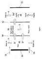
- the system includes a chromatographic separator, typically in the form of a chromatography column 10, which is packed with a chromatographic separation medium.
- the medium is in the form of ion exchange resin.
- the medium is a porous hydrophobic chromatographic resin as described in U.S. Patent No. 4,265,634 . Any chromatography separator can be used as is known to those skilled in the art.
- a suppressor-salt convertor 12 Arranged in series with column 10 is a suppressor-salt convertor 12 which serves to suppress the conductivity of the electrolyte of the eluent from column 10 but not the conductivity of the separated analyte ions.
- the analyte ions in the suppressed eluent are converted into an analyte salt stream in the downstream portion of suppressor-salt convertor 12 as described hereafter.
- the effluent from suppressor-salt convertor 12 is directed to a detector, preferably in the form of a flow-through conductivity cell 14, for detecting the separated or resolved analyte ions.
- a suitable sample stream of analyte ions is supplied through sample injection valve 16 which is passed through the system in the solution of eluent from eluent source reservoir 18 drawn by pump 20 and then passes through sample injection valve 16.
- the chromatography effluent solution leaving column 10 is directed to a suppressor zone in suppressor-salt convertor 12 in which the electrolyte is converted to a weakly conducting form.
- the analyte ions are converted to an analyte salt stream which is passed through conductivity cell 14 in which the presence of the analyte ions produces an electrical signal proportional to the amount of analyte ions.
- Such signal is typically directed from the cell to a conductivity meter, not shown, thus permitting detection of the concentration of separated analyte ions.
- the chromatography effluent is directed in line 22 through suppressor sample flow channel 24 of suppressor-salt convertor 12 separated by suppressor ion exchange membrane 26, having exchangeable ions of opposite charge to the analyte ions, from suppressor regenerant flow channel 28.
- the effluent from detector 14 can be recycled in line 30 stream supplied to the inlet of flow channel 28 and out line 32 to waste.
- the streams in flow channels 24 and 28 flow concurrently (in the same direction).
- the general configuration of suppressor-salt convertor 12 as illustrated in schematic form can be of the general type known in the IC field as a membrane suppressor. Any of the conventional forms of membrane suppressor may be used in accordance with the present invention such as the ones described in U.S. Patent Nos. 4,999,098 and 5,352,360 .
- a preferred form of membrane suppressor is illustrated in FIGS. 2-5 of those patents which illustrate an electrolytic "sandwich suppressor.” Instead of only including a single membrane as schematically illustrated in FIG. 1 herein, the embodiment of FIGS. 2-5 includes a central suppressor sample channel for chromatography effluent defined on both sides by flat permselective membrane sheets. Suppressor regenerant flow channels are defined on both sides of the sandwich suppressor. As illustrated schematically in FIG. 4 of U.S. Patent No. 5,352,360 , electrodes of opposite charge are disposed to communicate, respectively, with each of the suppressor regenerant flow channels. The present description will refer to this electrolytic form of membrane device.
- a suppressor of the general design sold by Dionex Corporation under the trademark ASRS suppressor can be used except that the system is set up so that all streams flow concurrently.
- ASRS suppressor the regenerant stream flows countercurrent to the chromatography effluent stream ensures that the tip of the suppressor is in suppressed form so that the membrane closest to the cathode is in the hydronium form.
- the electrolyte counterion (sodium) is predominantly drawn across the membrane in the upstream half of the device which is in cation form.
- the downstream portion of the analyte stream is substantially in the hydronium ion form.
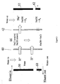
- FIG. 2 is a schematic view illustrating the reactions which occur in one embodiment of suppressor-salt convertor 12 of FIG. 1 used for the analysis of analyte anions.
- the suppressor of FIG. 2 includes two permselective ion exchange membranes 40 and 42 defining therebetween a central suppressor sample channel 44. Outside of membranes 40 and 42 are suppressor regenerant flow channels 46 and 48 contained within the interior walls by a suppressor not shown but illustrated in detail in the above patents. Electrodes in the form of anode 50 and cathode 52 communicate with the outer walls of channels 46 and 48, respectively.
- Ion exchange medium preferably in the form of ion exchange screens (not shown), are preferably included in channels 44, 46 and 48 and form a bridge between the electrodes on the outside of the channels and membranes 40 and 42 and between membranes 40 and 42 in the central channel.
- Effluent from chromatography column 12 flows through inlet 54 into channel 44, and out outlet 56 isolated from flow channels 46 and 48 by membranes 40 and 42 as illustrated in FIGS. 3 and 4 of U.S. Patent No. 5,352,360 .
- water is supplied as the regenerant stream in regenerant channels 46 and 48 flowing in the direction of arrow A.
- the upstream or suppression zone of suppressor-salt convertor 12 will be described.
- Water is electrolyzed in channel 46 to provide hydronium ion which passes through membrane 40.
- the electrolyte counterion is sodium which passes through membrane 42 under the influence of cathode 52. Hydroxide is converted to water in the chromatography effluent flowing through central channel 44 also in direction A.
- the sodium ion is converted to sodium hydroxide.
- the suppression zone reactions and conditions are substantially the same as the reactions that take place in the aforementioned Patent 5,352,360 .
- a feature of this embodiment which distinguishes from that patent is that the analyte ions flowing in the suppression zone sample eluent stream channel 44 are converted into a salt in a salt-forming zone by reaction with salt-forming ions of opposite charge.
- Such salt-forming ions comprise electrolyte counterions (e.g., sodium) removed during suppression.
- the salt-forming zone is coextensive with the outlet end of membranes 42 includes exchangeable ions in sodium form which supply the ions to convert the analyte to an analyte salt stream.
- Conditions in the salt-forming zone are selected so that suppression is substantially complete (the same degree of suppression as in a conventional suppressor with an ASRS suppressor) in the inlet or upstream portion of the suppressor.
- Sufficient electrolyte counterion is present at the downstream or exit end of the membrane 42 to permit conversion of the analyte ions to a salt form (e.g., NaA) wherein "A” represents analyte ion and "Na" is a representative counterion of the electrolyte.
- a salt form e.g., NaA
- suppressor-convertor 12 is an electrolytic sandwich configuration with concurrent flow of the chromatography effluent in channel 44 and the regenerant in channels 46 and 48 to effectuate substantially complete suppression in the upstream or suppression zone while simultaneously converting the analyte to salt form in the downstream or salt-forming zone at the outlet of the suppressor.
- One way to facilitate salt formation using concurrent streams in a conventional ASRS suppressor is to flow the suppressor effluent through the longer chamber of the ASRS device. This can be accomplished by reversing the polarity of the electrodes as illustrated schematically in FIG. 2 . Regenerant flow is also reversed and is concurrent with the eluent flow. At the inlet in the device, the eluent ions are drawn towards the cathode and replaced by the hydronium ions from the anode. The function of suppression is still maintained by the flux of hydronium ions and sodium ions through the ion exchange membranes.
- the electrode length can be shortened at the downstream or outlet end without changing the polarity of the device.
- the electrode length can be adjusted to extend extensively with about 30-90% of the upstream or inlet portions of the membranes bounding the central flow channel 44 of the device, preferably about 40 % to 60 % and most preferably about 50 %. In this way, the desired degree of conversion to a salt can be controlled because of a lack of potential being applied in part or all of the salt convertor zone.
- the degree of conversion to a salt form is dependent on the pKa and concentration of the analytes.
- the analyte has to be in the ionized form for good conversion.
- the extent of conversion can be monitored by comparing the peak response in the suppressed mode versus the salt formation mode. For strongly ionized species, the conversion to the salt form results in a decline in response when compared to the suppressed mode.
- the extent of conversion can be calculated from the expected conductivity response for a given analyte concentration which in turn can be calculated from the equivalent conductance and concentration of the individual ions. For weakly dissociated species, the conversion to the salt form results in improved linearity of response with concentration.
- salt conversion can be accomplished with at least about 10% of the outlet or downstream length of the membrane 42 exchangeable ions predominantly in the electrolyte counterion form, more preferably 30% to 90% and most preferably 40% to 60%.
- One suitable test for monitoring salt conversion is by plotting a response versus concentration curve for the detected analytes.
- a linear response for weakly dissociated species implies constant conversion.
- the length of the outlet or downstream length can be adjusted to allow for complete conversion in a desired range of concentration.
- the extent of ionization of some weakly dissociated species can be controlled by the extent of leakage across the membrane and this is done by adjusting the length of the outlet or downstream length.
- the degree of conversion to a salt is the salt-forming zone can be measured, e.g., by ion chromatography of the electrolyte counterion after salt formation.
- at least about 10% conversion takes place, preferably at least about 40-60 %, and more preferably at least about 80% to as high as about 95-100%.
- the outlet end of membranes 40 and 42 may be formed of material which has exchangeable ions of opposite polarity.
- the exit end of membranes 40 and 42 may be in the form of exchangeable cations. Similar spacial relations to the foregoing discussion of the shortening of the electrode length apply. The principle is that the system is adjusted to ensure that the outlet or downstream end of the membrane in the salt-forming zone is in the electrolyte counterion form.
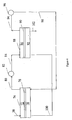
- FIG. 3 Another embodiment of the integral suppressor-ion convertor 12 is illustrated in FIG. 3 .
- the outlet ends of membranes 40 and 42 are maintained in electrolyte counterion form by the use of short electrodes of opposite polarity to anode 50 and cathode 52.
- Like parts will be designated by like numbers in FIGS. 2 and 3 .
- cathode 60 is disposed at the outlet end or downstream of anode 50 and an anode 62 is disposed at the outlet end or downstream of cathode 52.
- the relative length of the upstream electrodes for suppression and downstream electrodes for salt conversion can be adjusted depending upon the desired degree of conversion to the salt form while maintaining full conversion to the suppressed form in the upstream suppression portion of the suppressor.
- the upstream electrode is at least as long as the downstream electrode, preferably the ratio is at least 1:0.4, more preferably at least 1:0.2 or higher.
- the applied potential can be varied to adjust the degree of salt conversion.
- FIGS. 1-3 The system of FIGS. 1-3 has been described with respect to the analysis of anions. It is also applicable to the analysis of cations with an appropriate modification of the device to reverse polarity. Thus, the cathode and anode are reversed, the exchangeable ions of the suppressor ion exchange membrane are switched to the anion form rather than the cation form, and the electrolyte counterions are anionic, such as MSA, as is conventional in cation chromatography.
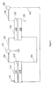
- FIG. 4 another embodiment of the invention is illustrated in which suppression and salt conversion are performed in separate communicating devices.
- the salt-forming communicates with but is remote from the suppression device.
- the sample effluent from chromatography flows in line 70 into the suppressor sample flow channel 72 of suppressor 74 separated by a suppressor ion exchange membrane 76 from suppressor regenerant flow channel 78.
- suppressor 74 can be a conventional electrolytic suppressor of the type sold under the ASRS trademark by Dionex Corporation with countercurrent flow. (A second set of downstream electrodes as described above may be used.)
- the suppressed chromatography effluent flows out line 80 into optional first detector 82 for detection of the suppressed resolved sample as a conventional chromatography.
- the effluent from detector 82 flows through line 84 into the salt convertor sample flow channel 86 of salt convertor 88 separated by salt convertor ion exchange membrane 90 from the salt convertor regenerant flow channel 92.
- flow in channels 86 and 92 is concurrent.
- Membrane 90 has exchangeable ions of the same charge as the electrolyte counterions.
- the function of salt convertor 88 is the same as the function of the salt-forming zone in the integral suppressor-salt convertor 12 of FIG. 1 . Similar principles apply for accomplishing salt conversion.
- One difference is that salt conversion is independent of suppression because they are accomplished in different devices.
- One advantage of this system is that it can be operated continuously with no external regenerant solution. Since in this system suppression is accomplished in the first device, both the suppressed and the salt form of the analytes can be monitored using independent detectors.
- the effluent from flow channel 86 flows through line 94 into a second detector 96 which detects the analyte ions in salt form as described for FIG. 1 .
- the effluent from detector 96 flows through line 98 and serves as the regenerant stream for suppressor regenerant flow channel 78.
- the effluent from channel 78 flows in line 100 to the inlet of salt convertor regenerant flow channel 92.
- the effluent from flow channel 92 flows to waste through line 102. In this system, no external regenerant stream is required for either suppressor 74 or salt convertor 88.
- the suppressor of WO 99/44054 could be used as the suppressor in a system using a remote salt convertor so that the suppressor effluent is the source of salt-forming ions.
- the analyte ions are first converted to salt form and optionally detected, as described above. Thereafter, the analyte salt is converted to an acid or base of the electrolyte counterions for improved conductivity during detection.
- the analyte ion is converted to MA.
- MA is converted to the base MOH.
- the electrolyte counterions are detected in hydroxide form, an indirect measure of the analyte ions in the sample.
- the acid or base convertor uses an ion exchange membrane with exchangeable ions of opposite charge to the ion exchange membrane in the salt convertor.
- a packed bed acid or base convertor may be employed.
- MSA For cation analysis, a typical eluent is MSA, and the analyte ion (e.g., Na + ) is converted to sodium.
- MSA form by a salt convertor either in integral form with the suppressor as in FIG. 1 or in a remote unit as in FIG. 4 .
- the NaMSA is converted to the HMSA acid form by passing through an anion suppressor such as the ASRS® suppressor sold by Dionex Corporation operated in a recycle mode.
- FIG. 5 illustrates one embodiment of the sequence of salt conversion followed by acid or base conversion.
- Suppressed chromatography effluent in line 110 is directed into the analyte flow channel 112 of salt convertor 114 separated from salt convertor regenerant flow channel 116 by salt convertor ion exchange membrane 118.
- the operation of salt convertor 114 can be the same as that of salt convertor 88 in FIG. 4 and so the description of that embodiment will be incorporated by reference.
- the sample effluent converted to an analyte salt in flow channel 112 flows through line 120 into detector 122 which detects the analyte salt in the stream.
- the analyte in 120 may be detected in detector 122 with part of it optionally flowing to waste in line 123.
- Effluent from detector 122 flows in line 124 into an acid or base convertor 126 wherein the analyte salt of the electrolyte counterion is converted into an acid or base of that counterion for subsequent detection.
- a suitable non-electrolytic acid or base convertor is of the type sold by Dionex Corporation under the trademark AMMSIII.
- the analyte salt in the form of MSA flows into acid or base convertor flow channel 128 which is separated from acid or base flow channel 130 by ion exchange membrane 132 having exchangeable ions of opposite charge to membrane 118 and thus of the same charge as the analyte cation.
- analyte cations are exchanged for hydronium ions to form the acid of the electrolyte counterion and the electrolyte counterion M is converted to the MOH for hydroxide form.
- the effluent from channel 116 flows in line 134 to the inlet side of flow channel 130 serving as the aqueous solution for continuously regenerating acid or base convertor 126.
- the effluent from channel 130 flows to waste in line 136.
- the acid or base channel 128 flows in line 138 to detector 140 and where the acid or base is detected.
- the effluent from detector 140 flows in line 142 and serves as the ion source in channel 116 for salt convertor 114.
- salt conversion may be accomplished in integral suppressor-salt convertor as illustrated in FIG. 1 followed by conversion to an acid or base in the manner described in FIG. 5 .
- the acid formed may be more conductive than the suppressed base form for both highly dissociated and partially dissociated analyte ions.
- sodium and ammonium as the analytes.
- the sodium and ammonium with counterions are converted to sodium hydroxide and ammonium hydroxide.
- the conversion to a salt in the salt convertor results in lower sensitivity for sodium because, for example, in the NaMSA form, MSA ion have a lower equivalent conductance than hydroxide ion.
- this conversion may result in improvement and sensitivity (depending on its concentration).
- the salt form for fully dissociated species has a lower response than the suppressed form.
- the MSA form On reconverting the analyte to the MSA acid form, the MSA form becomes more conductive than both the salt and the suppressed form. This is due to the fact that hydronium ion is more conductive than hydroxide ion. Thus, improved sensitivity for all cations may be achieved in this double conversion.
- FIG. 6 combining a salt convertor and an acid or base convertor similar to the system of FIG. 5 , is illustrated in FIG. 6 .
- an acid or base convertor using an electrolytic suppressor of the type sold by Dionex Corporation under the trademark ASRS is used for analysis of cations instead of the non-electrolytic acid or base convertor 126 described with respect to FIG. 5 .
- salt convertor 114 is of the same type as salt convertor 114 in FIG. 5 except for the source of regenerant solution.
- the inlet sample stream 110 is of the same type as in FIG. 5 .
- Like parts will be designated like numbers for FIGS. 5 and 6 .
- FIG. 5 in FIG.
- the effluent from detector 140 flows through line 150 and recycles to acid or base convertor 126 serving as the regenerant liquid source in channel 130 which flows countercurrently to the analyte salt flowing in channel 128.
- the effluent from channel 130 flows in line 152 to the inlet side of channel 116 in salt convertor 114.
- the effluent from channel 116 flows to waste in line 154.
- the flow systems of FIGS. 5 and 6 are different ways of accomplishing the same functions. First, conversion to salt and then to an acid or base.
- the packed bed suppressor of WO 99/44054 could be used as the acid or base convertor.
- FIG. 14 a packed bed form of salt convertor is illustrated in place of the membrane device salt convertors described above.
- the term "packed bed” refers to the packed bed of the type described in U.S. Patent No. 5,773,615 or alternative flow-through ion exchange materials such as disclosed in Example 7 of that patent.
- two packed bed devices are used in which one packed bed device is regenerated while the other one is used for salt conversion.
- the valve is switched to regenerate the exhausted suppressor while using the other regenerated packed bed device.
- the system of FIG. 14 using the electrolyte counterion as a source of regenerant could also be used with a single packed bed but this would require downtime or regeneration so it is less desirable than the continuous system of FIG. 14 .
- the chromatography portion of the system can be the same as that described above with respect to FIG. 1 through chromatography column 10 and line 22.
- the suppressor could be one or two packed bed suppressors such as described in U.S. Patent No. 5,597,734 .
- the effluent from the chromatography column flows in line 70 to the suppressor sample flow channel 72 of suppressor 74 separated by suppressor ion exchange membrane 76 from suppressor regenerant flow channel 78. Since the suppressor of FIG. 14 can be of the same type of the suppressor of FIG. 4 as described above, like numbers will be used to designate like parts in these two suppressors.
- the effluent from flow channel 72 flows through line 200 into conductivity cell 202 of the type described above.
- the effluent from detector 202 flows in line 204 to valve 206 and exits valve 206 in line 208 which flows into the first packed bed salt convertor 210 containing ion exchange material such as a packed bed of ion exchange resin 212 with exchangeable ion of opposite charge to the analyte ions.
- the analyte ions are converted into a salt form of the electrolyte counterion in an analogous but reversed way to suppression as described in U.S. Patent No. 5,773,615 . Salt conversion in a packed bed is also described in WO 9418555 .
- the principles in converting the acid or base form of the analyte into a salt are the same as those described above in that the acid or base form of the analyte is converted to the electrolyte counterion salt of the analyte.
- the electrolyte counterion is in weakly ionized form in line 200 with the analyte ion typically an acid or base form which can be detected as in conventional chromatography by conductivity detector 202.
- the salt converted analyte exiting convertor 210 flows in line 214 to a second valve 216 and from there in line 218 to a second conductivity cell 220 in which the analyte in salt form is detected.
- the effluent from conductivity detector 220 flows in line 222 to the inlet side of the regenerant flow channel 78 of suppressor 74. As described above, flow in channels 72 and 78 are countercurrent as in a conventional suppressor.
- the effluent from suppressor regenerant flow channel flows in line 224 back to valve 216 and into line 226 into the bottom of the second salt convertor 228 containing a packed bed of resin particles 230 as illustrated.
- the effluent stream from the regenerant flow channel 78 includes electrolyte counterions which have migrated across ion exchange membrane 76 according to the well known principles of membrane suppression. During salt conversion in packed bed 230, the electrolyte counterions are depleted and replaced by hydronium ions or hydroxide ions.
- packed bed 230 is regenerated by flowing the electrolyte counterions in line 224 through line 226 into packed bed 230 to convert the exchangeable ions of the ion exchange resin back into electrolyte counterion form. From there, the regenerant stream flows in line 232 back through valve 206 and to waste in line 240.
- the depleted packed bed used for salt conversion may be available in the hydronium or hydroxide form and may be used for the conventional suppression mode. This automatically converts the packed bed to the eluent counteranion or cation form.
- valves 206 and 216 are switched to reverse the flow of the analyte and regenerant streams flowing through convertors 210 and 228.
- convertor 210 is regenerated and convertor 230 is on-line with the analyte serving to convert the analyte to the salt.
- the system is used continuously with one packed bed salt convertor being used to convert the analyte to salt while the other one is being regenerated followed by valve switching for use of the other suppressor on-line for salt conversion while the first one is regenerated.
- This system can be used continuously with the electrolyte counterion which migrates across suppressor ion exchange membrane 76 being used as the regenerant for the packed bed salt convertor.
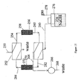
- FIG. 15 a system is illustrated for using two packed beds in which a first one is used on-line for salt conversion while the second one is regenerated followed by a switching of the valve so that the second salt convertor is on-line while the first one is regenerated.
- an external source of regenerant solution typically in the form of an acid or base such as the electrolyte used for the eluent, can be used for regeneration.
- a valving system can be used similar to that set forth in U.S. Patent No. 5,773,615 which describes an alternate suppression and regeneration of two packed bed suppressors followed by reversal of flow for continuous operation.
- FIG. 15 one embodiment of a continuous system for suppression and regeneration using two packed beds and an external regenerant reservoir is illustrated.
- a stream of chromatographically separated and suppressed analyte from a conventional suppressed ion chromatography system flows into the system in line 250 into valve 252 and from there through line 254 into first packed bed salt convertor 256 containing a packed bed of ion exchange particles 258 typically in the form of the electrolyte counterion.
- the ion exchange resin may be in the form of the electrolyte counterion or sodium.
- the electrolyte counterion may be in any form of the same charge as the electrolyte counterion such as other alkali metal salts such as lithium, cesium, or potassium.
- the analyte salt stream flows in line 260 to valve 262 and from there to a detector in the form of conductivity cell 266 and then through line 268 to waste.
- salt convertor 270 containing ion exchange packed bed 272 is regenerated.
- a solution of electrolyte counterion or other ions suitable for salt conversion 274 is contained in reservoir 276.
- a suitable pump such as pressurized gas in line 278 forces an electrolyte counterion in a liquid stream to flow through line 280 into valve 260. From there, the liquid flows in line 282 into the bottom of packed bed 272 and flows therethrough to regenerant exhausted exchangeable ions such as in the hydronium or hydroxide form into the form of the electrolyte counterion.
- the effluent stream from packed bed 270 flows through line 284 back through valve 252 and from there through line 286 to waste.
- the system is used with the illustrated valve setting while packed bed 256 contains sufficient electrolyte counterions to convert the analyte in line 254 to analyte salt in line 260.
- valves 252 and 260 are reversed.
- the electrolyte source from reservoir 276 flows upwardly through bed 258 to convert the exchangeable ions to electrolyte counterion form while convertor 270 is on-line converting analyte ion to analyte salt form.
- flow through the two packed beds is reversed so that one is used for salt conversion while the other one is regenerated followed by a reversal of the valving resulting in continuous operation of the system.
- the suppressors can be in the packed bed form rather than membrane suppressors.
- the membrane and packed bed devices of the present invention may be operated continuously or discontinuously as described above.
- first electrode communicating with a sample flow channel
- this encompasses direct communication (as by direct contact of the first electrode with the sample flow channel), or indirect communication (as by direct contact of the first electrode with the third flow channel adjacent to the second membrane separating the sample flow channel from the third flow channel in the sandwich membrane device), in which the first electrode is of opposite charge to the second electrode communicating (typically directly) with the interacting flow channel.
- This example illustrates the operation of the system of FIG. 1 .
- a Dionex Corporation DX500 system was used for this testing with a Dionex CS12a column and 20 mN MSA eluent.
- a commercially available Dionex CSRS ultra suppressor was used as the suppressor device and operated in the recycle mode of operation.
- the analytes comprised of a mixture of lithium, sodium, ammonium, potassium, calcium and magnesium.
- the CSRS ultra suppressor was first operated at 100 mA in the normal mode of operation.
- the regenerant flow was then switched to the concurrent flow mode (or reversed flow mode) as per the current invention and the device was powered at 100 mA.
- the chromatograms were compared as shown in FIG. 7 .
- the sensitivity for all the peaks were lower in the salt form, however, ammonia showed a higher relative response than the other ions in the salt form for this concentration..
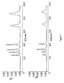
- This example shows the operation of the system of FIG. 1 .
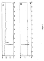
- a Dionex Corporation DX500 system was fitted with an AS 11 column and a gradient separation was attempted for a mixture of anions in both the normal and the reversed mode of operation.
- the analytes comprised of Bromate, Azide, Selinite, Sulfate and Phthalate ions.
- the gradient conditions were 0.5 mM to 30 mM NaOH for the first 16 minutes of operation and then up to 25 minutes at 30 mM NaOH for 1 ml/min.
- the suppressor was operated in the reversed mode of operation and the polarity was reversed to ensure that the tip of the suppressor was in the salt form.
- the results as shown in FIG. 10 indicated higher relative response for the weak acids in the salt form. Carbonate was poorly detected in the normal mode of operation and was detected with high sensitivity in the reversed mode of operation again demonstrating superior performance of the devices of the present invention.
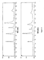
- a Dionex Corporation DX500 system was used for this testing with a Dionex CS12a column and 20 mN MSA eluent.
- a modified version of the 4 mm Dionex CSRS ultra suppressor was used as the suppressor device. The modification consisted of reducing the length of the anode to about 75% of the channel length. The net result of this change was a higher level of leakage of the regenerant across the suppressor as evident by the higher background.
- the suppressor was operated at 100 mA with the regenerant flow switched to the concurrent flow mode (or reversed flow mode) as per the current invention and the device was powered at 100 mA.
- the device produced negative peaks for an injection of 250-ppb concentration for a mixture of cations as shown in FIG. 11a .
- the device when injected with 750-ppb showed a mixture of both positive and negative peaks making integration difficult ( FIG. 11b ).
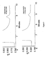
- the experimental setup was similar to Example 6 with the exception that an additional 2 mm AMMS device was used for converting the cation analytes to acid form.
- This setup is shown in FIG. 5 .
- the regenerant waste is diverted from the first suppressor to the AMMS suppressor in this mode.
- continuous conversion of the analytes to the eluent form is accomplished.
- the device is injected with the same samples from Example 6. Positive peaks with high sensitivity were observed as MSA and is shown in FIGS. 12a and 12b .
- the peak response in this mode was (area and height) higher than the salt form.
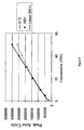
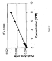
- the experimental setup was similar to Example 7 with the exception that a number of standards between 0 and 8 ppm were injected.
- the response versus concentration curves showed excellent linearity for all the cations including ammonia in the above concentration range. Correlation coefficient of greater than 0.999 was achieved for all of the ions. Response versus concentration curve for ammonia is shown in FIG. 13 .
Claims (34)
- Verfahren zur Suppressionsionenanalyse mehrerer verschiedener Analytionen in einer Probelösung, wobei jedes der Analytionen eine gewöhnliche Ladung, positiv oder negativ, aufweist, das Verfahren Folgendes umfassend:(a) Eluieren der Probelösung mit einem Eluent, welches Elektrolyt-Gegenionen entgegengesetzter Ladung zu den Analytionen umfasst, durch ein Trennmedium, welches wirksam ist, die Analytionen zu trennen, um einen Trennmedium-Ablaufstrom auszubilden,(b) Fließen des Trennmedium-Ablaufstroms durch eine Suppressionszone, in welcher Elektrolyt-Gegenionen entfernt werden, um den Elektrolyten in eine schwach ionisierte Form umzuwandeln, um einen Suppressorproben-Ablaufstrom auszubilden, und(c) Umwandeln der Analytionen in dem Suppressorproben-Ablaufstrom in Salze in einer salzbildenden Zone durch Reaktion mit salzbildenden Ionen entgegengesetzter Ladung, um einen Analytsalzstrom auszubilden,
dadurch gekennzeichnet, dass die salzbildenden Ionen entgegengesetzter Ladung Elektrolyt-Gegenionen umfassen, welche in der Suppressionszone entfernt werden. - Verfahren nach Anspruch 1, weiterhin umfassend den Schritt des (d) Detektierens der Analytionen in Salzform in dem Analytsalzstrom.
- Verfahren nach Anspruch 1, wobei Schritt (b) durchgeführt wird durch Fließen des Trennmedium-Ablaufstroms durch einen Suppressorproben-Strömungskanal (24, 44) in der Suppressorzone, welcher von einem Suppressorregenerationsmittel-Strömungskanal (28, 46, 48) durch eine Suppressor-Ionenaustauschmembran (26, 40, 42) getrennt ist, welche austauschbare Ionen entgegengesetzter Ladung zu den Analytionen aufweist, und Fließen eines Regenerationsmittelstroms durch den Suppressorregenerationsmittel-Strömungskanal (28, 46, 48), wobei die Elektrolyt-Gegenionen aus dem Trennmedium-Ablaufstrom durch Durchlassen durch die Suppressor-Ionenaustauschmembran (26, 40, 42) in den Suppressorregenerationsmittel-Strom entfernt werden, um einen Suppressorregenerationsmittel-Ablaufstrom auszubilden, welcher Elektrolyt-Gegenionen enthält.
- Verfahren nach Anspruch 3, wobei der Trennmedium-Ablaufstrom in dem Suppressorproben-Strömungskanal (24, 44) und der Suppressorregenerationsmittel-Strom in dem Suppressorregenerationsmittel-Strömungskanal (28, 46, 48) in die gleiche Richtung fließen.
- Verfahren nach Anspruch 3, wobei die salzbildende Zone koextensiv zu dem Auslassabschnitt der Suppressor-Ionenaustauschmembran (26, 40, 42) ist, wobei der Auslassabschnitt austauschbare Ionen in der Form der Elektrolyt-Gegenionen umfasst, von welchen ein Teil Salze mit den Probenanalytionen ausbildet.
- Verfahren nach Anspruch 5 für die Analyse von Anionenanalyten, in welchen ein elektrisches Potenzial über die Suppressor-Ionenaustauschmembran (26, 40, 42) in der Suppressionszone zwischen einer Anode (50), welche mit dem Suppressorproben-Strömungskanal (24, 44) in Verbindung steht, und einer Kathode (52) angelegt wird, welche mit dem Suppressorregenerationsmittel-Strömungskanal (28, 46, 48) in Verbindung steht.
- Verfahren nach Anspruch 6, wobei ein elektrisches Potenzial über die Suppressor-Ionenaustauschmembran (26, 40, 42) in der salzbildenden Zone zwischen einer Kathode, welche mit dem Suppressorproben-Strömungskanal (24, 44) in Verbindung steht, und einer Anode angelegt wird, welche mit dem Regenerationsmittel-Strömungskanal (28, 46, 48) in Verbindung steht.
- Verfahren nach Anspruch 5 für die Analyse von Kationenanalyten, in welchen ein elektrisches Potenzial über die Suppressor-Ionenaustauschmembran (26, 40, 42) in der Suppressionszone zwischen einer Kathode (52), welche mit dem Suppressorproben-Strömungskanal (24, 44) in Verbindung steht, und einer Anode (50) angelegt wird, welche mit dem Suppressorregenerationsmittel-Strömungskanal (28, 46, 48) in Verbindung steht.
- Verfahren nach Anspruch 8, wobei ein elektrisches Potenzial über die Suppressor-Ionenaustauschmembran (26, 40, 42) in der salzbildenden Zone zwischen einer Anode (50), welche mit dem Suppressorproben-Strömungskanal (24, 44) in Verbindung steht, und einer Kathode (52) angelegt wird, welche mit dem Regenerationsmittel-Strömungskanal (28, 46, 48) in Verbindung steht.
- Verfahren nach Anspruch 6, wobei kein elektrisches Potenzial über mindestens einen Abschnitt der salzbildenden Zone angelegt wird.
- Verfahren nach Anspruch 3, wobei Schritt (c) durchgeführt wird durch Fließen des Suppressorregenerationsmittel-Ablaufstroms durch eine salzbildende Zone, welche von der Suppressionszone entfernt ist und einen Salzwandler-Regenerationsmittel-Strömungskanal (92) aufweist, welcher durch eine Salzwandler-Ionenaustauschmembran (90), welche austauschbare Ionen entgegengesetzter Ladung zu den Analytionen aufweist, von einem analytsalzbildenden Strömungskanal (86) getrennt ist, und durch Fließen des Suppressorprobenstroms durch den analytsalzbildenden Strömungskanal (86), wobei die Elektrolyt-Gegenionen aus dem Salzwandler-Regenerationsmittel-Strömungskanal (92) durch die Salzwandler-Ionenaustauschmembran (90) aus dem Regenerationsmittel-Ablaufstrom in den analytsalzbildenden Strömungskanal (86) passieren, um den Analytsalzstrom auszubilden.
- Verfahren nach Anspruch 11, wobei ein elektrisches Potenzial über die Salzwandler-Ionenaustauschmembran (90) zwischen einer Kathode (52), welche mit dem analytsalzbildenden Strömungskanal (86) in Verbindung steht, und einer Anode (50) angelegt wird, welche mit dem Salzwandler-Regenerationsmittel-Strömungskanal (92) in Verbindung steht.
- Verfahren nach Anspruch 11, wobei ein elektrisches Potenzial über die Salzwandler-Ionenaustauschmembran (90) zwischen einer Anode (50), welche mit dem analytsalzbildenden Strömungskanal (86) in Verbindung steht, und einer Kathode (52) angelegt wird, welche mit dem Salzwandler-Regenerationsmittel-Strömungskanal (92) in Verbindung steht.
- Verfahren nach Anspruch 11, weiterhin den folgenden Schritt umfassend: (d) Detektieren der Analytionen in Salzform in dem Analytsalzstrom.
- Verfahren nach Anspruch 14, wobei nach Detektion bei Schritt (d) der Analytsalzstrom in dem Suppressorregenerationsmittel-Strömungskanal (28, 46, 48) wiederverwertet wird.
- Verfahren nach Anspruch 11, wobei ein elektrisches Potenzial über die Salzwandler-Ionenaustauschmembran (90) zwischen einer ersten und einer zweiten Elektrode entgegengesetzter Ladung angelegt wird, welche mit dem Salzwandler-Regenerationsmittel-Strömungskanal (92) bzw. mit dem analytsalzbildenden Strömungskanal (86) in Verbindung stehen.
- Verfahren nach Anspruch 16, wobei die Analytionen negative Ladung aufweisen, die erste Elektrode eine Anode (50) ist und die zweite Elektrode eine Kathode (52) ist.
- Verfahren nach Anspruch 16, wobei die Analytionen positive Ladung aufweisen, die erste Elektrode eine Kathode (52) ist und die zweite Elektrode eine Anode (50) ist.
- Verfahren nach Anspruch 11, wobei die Ströme in dem analytsalzbildenden Strömungskanal (86) und in dem Salzwandler-Regenerationsmittel-Strömungskanal (92) in die gleiche Richtung fließen.
- Verfahren nach Anspruch 1, weiterhin den folgenden Schritt umfassend:(d) Fließen des Analytsalzstroms durch einen Säure- oder Basewandler (126), um einen Ablaufstrom auszubilden, welcher eine Säure der Elektrolyt-Gegenionen für Analytionen positiver Ladung und eine Base der Elektrolyt-Gegenionen für Analytionen negativer Ladung umfasst, und(e) Detektieren der Elektrolyt-Gegenionen in dem Säure- oder Baseelektrolyt-Gegenion-Ablaufstrom.
- Verfahren nach Anspruch 20, wobei Schritt (d) durchgeführt wird durch Fließen des Analytsalzstroms durch einen Probenströmungskanal (128) des Säure- oder Basewandlers (126), welcher durch eine Säure- oder Basewandler-Ionenaustauschmembran (132) mit austauschbaren Ionen der gleichen Ladung wie die Analytionen von einem Säure- oder Basewandler-Regenerationsmittel-Strömungskanal (130) getrennt ist, und durch Fließen eines Säure- oder Basestroms durch den Säure- oder Basewandler-Regenerationsmittel-Strömungskanal (130).
- Verfahren nach Anspruch 21, wobei nach Detektion bei Schritt (e) der Säure- oder Baseelektrolyt-Gegenion-Ablaufstrom in dem Säure- oder Basewandler-Regenerationsmittel-Strömungskanal (130) wiederverwertet wird.
- Verfahren nach Anspruch 1, wobei die salzbildende Zone mindestens einen ersten Schüttschicht-Salzwandler (210) umfasst, welcher ein Ionenaustauschmedium mit austauschbaren Elektrolyt-Gegenionen umfasst, welche in der Suppressionszone entfernt werden.
- Verfahren nach Anspruch 23, wobei der erste Schüttschicht-Salzwandler (210) durch einen Strom der Eluentelektrolyt-Gegenionen periodisch regeneriert wird, welche aus der Suppressionszone entfernt werden.
- Verfahren nach Anspruch 24, einen zweiten Schüttschicht-Salzwandler umfassend, welcher ein Ionenaustauschmedium mit austauschbaren Elektrolyt-Gegenionen umfasst, welche durch einen Strom der Eluentelektrolyt-Gegenionen regeneriert werden, welche aus der Suppressionszone entfernt werden.
- Verfahren nach Anspruch 25, wobei der Strom zu dem ersten und zu dem zweiten Schüttschicht-Salzwandler umgekehrt ist, so dass der erste Schüttschicht-Salzwandler regeneriert wird, während der zweite die Analytionen in einen Analytsalzstrom umwandelt.
- Verfahren nach Anspruch 1 zur Suppressionsionenanalyse mehrerer Analytionen in einer Probelösung, wobei jedes der Analytionen eine gewöhnliche Ladung, positiv oder negativ, aufweist,
wobei der Suppressorproben-Ablaufstrom einen Suppressionszonen-Ablaufstrom ausbildet, welcher die Analytionen in Säure- oder Baseform umfasst,
wobei Schritt (c) Umwandeln der Analytionen in dem Suppressionszone-Ablaufstrom in ein Salz in einem ersten Schüttschicht-Salzwandler, welcher ein Ionenaustauschmedium mit austauschbaren Kationen oder Anionen umfasst, durch Reaktion mit Ionen entgegengesetzter Ladung zu den Analytionen umfasst, welche die Elektrolyt-Gegenionen umfassen, welche in der Suppressionszone entfernt werden, um einen ersten Analytsalzstrom auszubilden,
und wobei das Verfahren weiterhin Folgendes umfasst:(d) Regenerieren eines mindestens teilweise erschöpften zweiten Schüttschicht-Salzwandlers zu salzbildenden Kationen oder Anionen gleichzeitig mit Schritt (c),(e) Detektieren der Analytionen in dem ersten Analytsalzstrom,(f) Umkehren einer Strömung durch den ersten und durch den zweiten Schüttschicht-Salzwandler, so dass der erste regeneriert wird, während ein zweiter Analytsalzstrom in dem zweiten Schüttschicht-Salzwandler ausgebildet wird, und(g) Detektieren der Analytionen in dem zweiten Analytsalzstrom. - Vorrichtung zur Suppressionsionenanalyse von Analytionen in einer Probelösung, die Vorrichtung Folgendes umfassend:(a) einen chromatographischen Abscheider (10) mit einem Einlass und einem Auslass zum Trennen der Analytionen in der Gegenwart eines Eluents, welches Elektrolyt-Gegenionen entgegengesetzter Ladung zu den Analytionen umfasst,(b) einen Suppressorsalzwandler, welcher einen Suppressorproben-Strömungskanal (24, 44) umfasst, welcher von einem Suppressorregenerationsmittel-Strömungskanal (28, 46, 48) durch eine Suppressor-Ionenaustauschmembran (26, 40, 42) getrennt ist, welche einen stromaufwärtigen Abschnitt und einen stromabwärtigen salzbildenden Abschnitt aufweist, wobei der Suppressorregenerationsmittel-Strömungskanal (28, 46, 48) einen Einlass und einen Auslass aufweist und der Suppressorproben-Strömungskanal (24, 44) einen Auslass und einen Einlass aufweist, welcher mit dem chromatographischen Abscheiderauslass in Verbindung steht,
dadurch gekennzeichnet, dass(c) der Suppressorproben-Strömungskanalauslass mit dem Suppressorregenerationsmittel-Strömungskanaleinlass in Verbindung steht, und(d) der Suppressorproben-Strömungskanaleinlass und der Suppressorregenerationsmittel-Strömungskanaleinlass auf der stromaufwärtigen Seite jedes der Strömungskanäle angeordnet sind, welche derartig mit gleichzeitiger Strömung konfiguriert sind, dass die Suppressor-Ionenaustauschmembran (26, 40, 42) in dem stromabwärtigen salzbildenden Abschnitt austauschbare Ionen aufweist, welche in dem Suppressorproben-Strömungskanal durch die Elektrolyt-Gegenionen entfernt werden, welche dazu dienen, die Analytionen in Salze der Elektrolyt-Gegenionen umzuwandeln. - Vorrichtung nach Anspruch 28, weiterhin umfassend einen Säure- oder Basewandler (126), welcher einen Säure- oder Basewandlerproben-Strömungskanal (128) umfasst, welcher einen Einlass und einen Auslass aufweist und durch eine Säure- oder Basewandler-Ionenaustauschmembran (132) von einem Säure- oder Baseumwandlungs-Strömungskanal (130) getrennt ist, welcher einen Einlass und einen Auslass aufweist, wobei die Ionenaustauschmembran (132) austauschbare Ionen gleicher Ladung wie die Analytionen umfasst, wobei der Säure- oder Basewandlerproben-Strömungskanaleinlass mit dem Suppressorproben-Strömungskanalauslass in Verbindung steht.
- Vorrichtung zur Suppressionsionenanalyse von Analytionen in einer Probelösung, die Vorrichtung Folgendes umfassend:(a) einen chromatographischen Abscheider (10) mit einem Einlass und einem Auslass zum Trennen der Analytionen in der Gegenwart eines Eluents, welches Elektrolyt-Gegenionen entgegengesetzter Ladung zu den Analytionen umfasst, um einen Trennmedium-Ablaufstrom auszubilden,(b) einen Suppressor, welcher einen Suppressorproben-Strömungskanal (24, 44) umfasst, welcher einen Einlass und einen Auslass aufweist und von einem Suppressorregenerationsmittel-Strömungskanal (28, 46, 48), welcher einen Einlass und einen Auslass aufweist, durch eine Suppressor-Ionenaustauschmembran (26, 40, 42) getrennt ist, wobei der Suppressorproben-Strömungskanaleinlass mit dem chromatographischen Abscheiderauslass in Verbindung steht, und(c) einen Salzwandler (114), welcher eine Salzwandler-Ionenaustauschmembran (118) umfasst, welche einen analytsalzbildenden Strömungskanal (112), welcher einen Einlass und einen Auslass aufweist, von einem Salzwandler-Regenerationsmittel-Strömungskanal (116) trennt, welcher einen Einlass und einen Auslass aufweist, wobei der analytsalzbildende Strömungskanaleinlass mit dem Suppressorproben-Strömungskanalauslass in Verbindung steht, dadurch gekennzeichnet, dass
der Salzwandler-Regenerationsmittel-Strömungskanaleinlass mit dem Suppressorregenerationsmittel-Strömungskanalauslass in Verbindung steht, und
der analytsalzbildende Strömungskanalauslass mit dem Suppressorregenerationsmittel-Strömungskanaleinlass in Verbindung steht. - Vorrichtung nach Anspruch 30, wobei der Salzwandler-Regenerationsmittel-Strömungskanaleinlass und der analytsalzbildende Strömungskanaleinlass nahe ihren stromaufwärtigen Enden angeordnet sind, so dass eine Strömung durch sie hindurch in die gleiche Richtung fließt.
- Vorrichtung nach Anspruch 30, weiterhin umfassend einen Säure- oder Basewandler (126), welcher einen Säure- oder Basewandlerproben-Strömungskanal (128) umfasst, welcher einen Einlass und einen Auslass aufweist und durch eine Säure- oder Basewandler-Ionenaustauschmembran (132) von einem Säure- oder Baseumwandlungs-Strömungskanal (130) getrennt ist, welcher einen Einlass und einen Auslass aufweist, wobei die Ionenaustauschmembran (132) austauschbare Ionen gleicher Ladung wie die Analytionen umfasst.
- Vorrichtung nach Anspruch 32, weiterhin umfassend einen Detektor (140) mit einem Einlass und einem Auslass, wobei der Säure- oder Basewandlerproben-Strömungskanalauslass mit dem Detektoreinlass in Verbindung steht und der Detektorauslass mit dem Säure- oder Baseumwandlungs-Strömungskanaleinlass in Verbindung steht.
- Vorrichtung nach Anspruch 32, weiterhin umfassend einen Detektor (140) mit einem Einlass und einem Auslass, wobei der Säure- oder Basewandlerproben-Strömungskanalauslass mit dem Detektoreinlass in Verbindung steht und der Detektorauslass mit dem Suppressor-Regenerationsmittel-Strömungskanaleinlass in Verbindung steht.
Applications Claiming Priority (3)
| Application Number | Priority Date | Filing Date | Title |
|---|---|---|---|
| US797914 | 1985-11-14 | ||
| US09/797,914 US6752927B2 (en) | 2001-03-01 | 2001-03-01 | Suppressed chromatography and salt conversion system |
| PCT/US2002/006227 WO2002071052A2 (en) | 2001-03-01 | 2002-02-28 | Suppressed chromatography and salt conversion system |
Publications (2)
| Publication Number | Publication Date |
|---|---|
| EP1373882A2 EP1373882A2 (de) | 2004-01-02 |
| EP1373882B1 true EP1373882B1 (de) | 2015-09-02 |
Family
ID=25172084
Family Applications (1)
| Application Number | Title | Priority Date | Filing Date |
|---|---|---|---|
| EP02715016.8A Expired - Lifetime EP1373882B1 (de) | 2001-03-01 | 2002-02-28 | Suppressionschromatographie- und salzumwandlungsvorrichtung |
Country Status (6)
| Country | Link |
|---|---|
| US (2) | US6752927B2 (de) |
| EP (1) | EP1373882B1 (de) |
| JP (1) | JP4122228B2 (de) |
| AU (1) | AU2002247237B2 (de) |
| CA (1) | CA2439258C (de) |
| WO (1) | WO2002071052A2 (de) |
Families Citing this family (23)
| Publication number | Priority date | Publication date | Assignee | Title |
|---|---|---|---|---|
| US6752927B2 (en) * | 2001-03-01 | 2004-06-22 | Dionex Corporation | Suppressed chromatography and salt conversion system |
| US7128823B2 (en) | 2002-07-24 | 2006-10-31 | Applied Materials, Inc. | Anolyte for copper plating |
| WO2006023985A2 (en) * | 2004-08-23 | 2006-03-02 | Remote Clinical Solutions, Inc. | System and method for modifying a fluid for oral administration |
| EP2747880B1 (de) | 2011-08-23 | 2021-03-24 | Board Of Regents, The University Of Texas System | Elektrolytpuffergenerator |
| US10048233B2 (en) | 2012-11-12 | 2018-08-14 | Dionex Corporation | Suppressor device |
| US9964510B2 (en) | 2013-09-16 | 2018-05-08 | Dionex Corporation | Electrolytic four-channel device and method |
| US9625430B2 (en) | 2013-10-18 | 2017-04-18 | Dionex Corporation | Multielectrode electrolytic device and method |
| US11090606B2 (en) | 2013-12-05 | 2021-08-17 | Dionex Corporation | Gas-less electrolytic device and method |
| US20170051344A1 (en) * | 2014-01-24 | 2017-02-23 | Life Technologies Corporation | Purification Chemistries and Formats for Sanger DNA Sequencing Reactions on a Micro-Fluidics Device |
| JP6379594B2 (ja) * | 2014-03-31 | 2018-08-29 | 東ソー株式会社 | イオン化合物のイオン変換方法及びイオン変換装置 |
| JP6379593B2 (ja) * | 2014-03-31 | 2018-08-29 | 東ソー株式会社 | イオン化合物のイオン変換方法およびイオン変換装置 |
| US9931585B2 (en) | 2014-04-23 | 2018-04-03 | Dionex Corporation | Electrolytic device for contaminant removal and method |
| US20160137530A1 (en) * | 2014-11-13 | 2016-05-19 | Dionex Corporation | Ion exchange based volatile component removal device for ion chromatography |
| JP6631131B2 (ja) * | 2015-09-30 | 2020-01-15 | 東ソー株式会社 | イオン化合物のイオン変換方法及びイオン変換装置 |
| JP6578863B2 (ja) * | 2015-09-30 | 2019-09-25 | 東ソー株式会社 | イオン化合物のイオン変換方法及びイオン変換装置 |
| JP6597138B2 (ja) * | 2015-09-30 | 2019-10-30 | 東ソー株式会社 | イオン化合物のイオン変換方法及びイオン変換装置 |
| JP6631132B2 (ja) * | 2015-09-30 | 2020-01-15 | 東ソー株式会社 | イオン化合物のイオン変換方法及びイオン変換装置 |
| US11287403B2 (en) * | 2016-01-07 | 2022-03-29 | Board Of Regents, The University Of Texas System | Ion chromatography system and methods utilizing a weak acid or weak base extraction device |
| US10948466B2 (en) * | 2017-03-03 | 2021-03-16 | Dionex Corporation | Flow control in an electrolytic reagent concentrator for ion chromatography |
| WO2020194608A1 (ja) * | 2019-03-27 | 2020-10-01 | 株式会社島津製作所 | イオンクロマトグラフ |
| CN111214848B (zh) * | 2020-01-20 | 2020-11-20 | 青岛盛瀚色谱技术有限公司 | 一种离子色谱抑制器 |
| CN112782335A (zh) * | 2020-12-29 | 2021-05-11 | 中国水产科学研究院黄海水产研究所 | 一种采用离子色谱同步检测大气中mma+、dma+、tma+和dea+的方法 |
| US20230184728A1 (en) * | 2021-12-09 | 2023-06-15 | Dionex Corporation | Suppressor |
Citations (1)
| Publication number | Priority date | Publication date | Assignee | Title |
|---|---|---|---|---|
| US4999098A (en) * | 1984-10-04 | 1991-03-12 | Dionex Corporation | Modified membrane suppressor and method for use |
Family Cites Families (26)
| Publication number | Priority date | Publication date | Assignee | Title |
|---|---|---|---|---|
| US3920397A (en) | 1973-08-06 | 1975-11-18 | Dow Chemical Co | Apparatus and method for quantitative analysis of ionic species by liquid column chromatography |
| US3897213A (en) | 1973-08-06 | 1975-07-29 | Dow Chemical Co | Automated quantitative analysis of ionic species |
| US3926559A (en) | 1973-08-06 | 1975-12-16 | Dow Chemical Co | Method and apparatus for quantitative chromatographic analysis of cationic species |
| US3925019A (en) | 1973-08-06 | 1975-12-09 | Dow Chemical Co | Chromatographic analysis of ionic species |
| US4474664A (en) | 1980-01-16 | 1984-10-02 | The Dow Chemical Company | Ion analysis method and apparatus |
| US4265634A (en) | 1980-03-10 | 1981-05-05 | Dionex Corporation | Chromatographic separation and quantitative analysis of ionic species |
| US4751004A (en) | 1981-09-18 | 1988-06-14 | The Dow Chemical Company | Liquid chromatographic method and apparatus with a packed tube membrane device for post-column derivatization/suppression reactions |
| US4455233A (en) | 1983-08-12 | 1984-06-19 | Dionex Corporation | Method and apparatus for ion analysis and detection using reverse mode suppression |
| US4861555A (en) | 1985-03-11 | 1989-08-29 | Applied Automation, Inc. | Apparatus for chromatographic analysis of ionic species |
| JPS6270757A (ja) | 1985-09-25 | 1987-04-01 | Toyo Soda Mfg Co Ltd | 液体クロマトグラフイ−による分離・分析方法及び分離・分析装置 |
| US4751189A (en) | 1986-03-11 | 1988-06-14 | Dionex Corporation | Method for balancing background conductivity for ion chromatography |
| US5045204A (en) | 1990-02-13 | 1991-09-03 | Dionex Corporation | Method and apparatus for generating a high purity chromatography eluent |
| US5068090A (en) | 1990-03-26 | 1991-11-26 | The Babcock & Wilcox Company | Aqueous carbon dioxide monitor |
| US5248426A (en) | 1992-02-10 | 1993-09-28 | Dionex Corporation | Ion chromatography system using electrochemical suppression and detector effluent recycle |
| WO1994018555A1 (en) * | 1993-02-02 | 1994-08-18 | Dionex Corporation | Sequential ion chromatography and conversion system |
| DE69418303T3 (de) | 1993-08-27 | 2002-07-04 | Dionex Corp | Ionenchromatographie unter benutzung häufiger regeneration eines chargenartigen unterdrückers |
| US5633171A (en) | 1995-03-03 | 1997-05-27 | Dionex Corporation | Intermittent electrolytic packed bed suppressor regeneration for ion chromatography |
| EP1366817B1 (de) * | 1995-03-03 | 2012-02-29 | Dionex Corporation | System zur Erzeugung eines hochreinen Eluenten durch Wasserelektrolyse |
| US6325976B1 (en) | 1998-02-26 | 2001-12-04 | Dionex Corporation | Continuous electrolytically regenerated packed bed suppressor for ion chromatography |
| US6077434A (en) | 1999-01-15 | 2000-06-20 | Dionex Corporation | Current-efficient suppressors and method of use |
| US6468804B1 (en) | 1999-08-02 | 2002-10-22 | Alltech Associates, Inc. | Suppressor for continuous electrochemically suppressed ion chromatography and method |
| US6436719B1 (en) | 2000-03-08 | 2002-08-20 | Dionex Corporation | Displacement chemical regeneration method and apparatus |
| US6752927B2 (en) * | 2001-03-01 | 2004-06-22 | Dionex Corporation | Suppressed chromatography and salt conversion system |
| US6808608B2 (en) * | 2002-03-13 | 2004-10-26 | Dionex Corporation | Water purifier and method |
| US7517696B2 (en) * | 2003-01-30 | 2009-04-14 | Dionex Corporation | Chemical suppressors and method of use |
| US7473354B2 (en) * | 2005-09-16 | 2009-01-06 | Dionex Corporation | Recycled suppressor regenerants |
-
2001
- 2001-03-01 US US09/797,914 patent/US6752927B2/en not_active Expired - Lifetime
-
2002
- 2002-02-28 WO PCT/US2002/006227 patent/WO2002071052A2/en active Application Filing
- 2002-02-28 JP JP2002569923A patent/JP4122228B2/ja not_active Expired - Fee Related
- 2002-02-28 EP EP02715016.8A patent/EP1373882B1/de not_active Expired - Lifetime
- 2002-02-28 AU AU2002247237A patent/AU2002247237B2/en not_active Ceased
- 2002-02-28 CA CA2439258A patent/CA2439258C/en not_active Expired - Fee Related
-
2004
- 2004-04-27 US US10/833,458 patent/US7618535B2/en active Active
Patent Citations (1)
| Publication number | Priority date | Publication date | Assignee | Title |
|---|---|---|---|---|
| US4999098A (en) * | 1984-10-04 | 1991-03-12 | Dionex Corporation | Modified membrane suppressor and method for use |
Also Published As
| Publication number | Publication date |
|---|---|
| AU2002247237B2 (en) | 2007-02-08 |
| JP2004522970A (ja) | 2004-07-29 |
| CA2439258C (en) | 2010-06-01 |
| US20040195100A1 (en) | 2004-10-07 |
| US7618535B2 (en) | 2009-11-17 |
| US20020162804A1 (en) | 2002-11-07 |
| WO2002071052A3 (en) | 2003-02-27 |
| WO2002071052A2 (en) | 2002-09-12 |
| EP1373882A2 (de) | 2004-01-02 |
| JP4122228B2 (ja) | 2008-07-23 |
| US6752927B2 (en) | 2004-06-22 |
| CA2439258A1 (en) | 2002-09-12 |
Similar Documents
| Publication | Publication Date | Title |
|---|---|---|
| EP1373882B1 (de) | Suppressionschromatographie- und salzumwandlungsvorrichtung | |
| AU2002247237A1 (en) | Suppressed chromatography and salt conversion system | |
| US8636963B2 (en) | Chemical suppressors and method of use | |
| US5633171A (en) | Intermittent electrolytic packed bed suppressor regeneration for ion chromatography | |
| US6325976B1 (en) | Continuous electrolytically regenerated packed bed suppressor for ion chromatography | |
| AU731200B2 (en) | Acid or base generator and method of use | |
| CA2498217A1 (en) | Electrolytic eluent generator and method of use | |
| WO1998032011A9 (en) | Acid or base generator and method of use | |
| EP1261866B1 (de) | Verfahren und vorrichtung zur gasassistierten unterdrückten chromatographie |
Legal Events
| Date | Code | Title | Description |
|---|---|---|---|
| PUAI | Public reference made under article 153(3) epc to a published international application that has entered the european phase |
Free format text: ORIGINAL CODE: 0009012 |
|
| 17P | Request for examination filed |
Effective date: 20030905 |
|
| AK | Designated contracting states |
Kind code of ref document: A2 Designated state(s): AT BE CH CY DE DK ES FI FR GB GR IE IT LI LU MC NL PT SE TR |
|
| AX | Request for extension of the european patent |
Extension state: AL LT LV MK RO SI |
|
| REG | Reference to a national code |
Ref country code: HK Ref legal event code: DE Ref document number: 1061272 Country of ref document: HK |
|
| 17Q | First examination report despatched |
Effective date: 20090820 |
|
| GRAP | Despatch of communication of intention to grant a patent |
Free format text: ORIGINAL CODE: EPIDOSNIGR1 |
|
| RIC1 | Information provided on ipc code assigned before grant |
Ipc: G01N 30/02 20060101ALN20140917BHEP Ipc: B01D 15/36 20060101ALI20140917BHEP Ipc: G01N 30/96 20060101AFI20140917BHEP |
|
| RIC1 | Information provided on ipc code assigned before grant |
Ipc: G01N 30/96 20060101AFI20140922BHEP Ipc: G01N 30/02 20060101ALN20140922BHEP Ipc: B01D 15/36 20060101ALI20140922BHEP |
|
| INTG | Intention to grant announced |
Effective date: 20141015 |
|
| RIN1 | Information on inventor provided before grant (corrected) |
Inventor name: SAINI, SHEETAL Inventor name: AVDALOVIC, NEBOJSA Inventor name: SRINIVASAN, KANNAN |
|
| REG | Reference to a national code |
Ref country code: DE Ref legal event code: R079 Ref document number: 60247436 Country of ref document: DE Free format text: PREVIOUS MAIN CLASS: G01N0030020000 Ipc: G01N0030960000 |
|
| RIC1 | Information provided on ipc code assigned before grant |
Ipc: G01N 30/02 20060101ALN20150204BHEP Ipc: B01D 15/36 20060101ALI20150204BHEP Ipc: G01N 30/96 20060101AFI20150204BHEP |
|
| GRAP | Despatch of communication of intention to grant a patent |
Free format text: ORIGINAL CODE: EPIDOSNIGR1 |
|
| INTG | Intention to grant announced |
Effective date: 20150317 |
|
| GRAS | Grant fee paid |
Free format text: ORIGINAL CODE: EPIDOSNIGR3 |
|
| GRAA | (expected) grant |
Free format text: ORIGINAL CODE: 0009210 |
|
| AK | Designated contracting states |
Kind code of ref document: B1 Designated state(s): AT BE CH CY DE DK ES FI FR GB GR IE IT LI LU MC NL PT SE TR |
|
| REG | Reference to a national code |
Ref country code: GB Ref legal event code: FG4D |
|
| REG | Reference to a national code |
Ref country code: AT Ref legal event code: REF Ref document number: 746941 Country of ref document: AT Kind code of ref document: T Effective date: 20150915 Ref country code: CH Ref legal event code: EP |
|
| REG | Reference to a national code |
Ref country code: IE Ref legal event code: FG4D |
|
| REG | Reference to a national code |
Ref country code: DE Ref legal event code: R096 Ref document number: 60247436 Country of ref document: DE |
|
| REG | Reference to a national code |
Ref country code: AT Ref legal event code: MK05 Ref document number: 746941 Country of ref document: AT Kind code of ref document: T Effective date: 20150902 |
|
| PG25 | Lapsed in a contracting state [announced via postgrant information from national office to epo] |
Ref country code: GR Free format text: LAPSE BECAUSE OF FAILURE TO SUBMIT A TRANSLATION OF THE DESCRIPTION OR TO PAY THE FEE WITHIN THE PRESCRIBED TIME-LIMIT Effective date: 20151203 Ref country code: FI Free format text: LAPSE BECAUSE OF FAILURE TO SUBMIT A TRANSLATION OF THE DESCRIPTION OR TO PAY THE FEE WITHIN THE PRESCRIBED TIME-LIMIT Effective date: 20150902 |
|
| REG | Reference to a national code |
Ref country code: NL Ref legal event code: MP Effective date: 20150902 |
|
| PG25 | Lapsed in a contracting state [announced via postgrant information from national office to epo] |
Ref country code: ES Free format text: LAPSE BECAUSE OF FAILURE TO SUBMIT A TRANSLATION OF THE DESCRIPTION OR TO PAY THE FEE WITHIN THE PRESCRIBED TIME-LIMIT Effective date: 20150902 Ref country code: SE Free format text: LAPSE BECAUSE OF FAILURE TO SUBMIT A TRANSLATION OF THE DESCRIPTION OR TO PAY THE FEE WITHIN THE PRESCRIBED TIME-LIMIT Effective date: 20150902 Ref country code: AT Free format text: LAPSE BECAUSE OF FAILURE TO SUBMIT A TRANSLATION OF THE DESCRIPTION OR TO PAY THE FEE WITHIN THE PRESCRIBED TIME-LIMIT Effective date: 20150902 |
|
| PG25 | Lapsed in a contracting state [announced via postgrant information from national office to epo] |
Ref country code: NL Free format text: LAPSE BECAUSE OF FAILURE TO SUBMIT A TRANSLATION OF THE DESCRIPTION OR TO PAY THE FEE WITHIN THE PRESCRIBED TIME-LIMIT Effective date: 20150902 Ref country code: IT Free format text: LAPSE BECAUSE OF FAILURE TO SUBMIT A TRANSLATION OF THE DESCRIPTION OR TO PAY THE FEE WITHIN THE PRESCRIBED TIME-LIMIT Effective date: 20150902 |
|
| PGFP | Annual fee paid to national office [announced via postgrant information from national office to epo] |
Ref country code: CH Payment date: 20160211 Year of fee payment: 15 Ref country code: DE Payment date: 20160223 Year of fee payment: 15 |
|
| PG25 | Lapsed in a contracting state [announced via postgrant information from national office to epo] |
Ref country code: PT Free format text: LAPSE BECAUSE OF FAILURE TO SUBMIT A TRANSLATION OF THE DESCRIPTION OR TO PAY THE FEE WITHIN THE PRESCRIBED TIME-LIMIT Effective date: 20160104 Ref country code: BE Free format text: LAPSE BECAUSE OF NON-PAYMENT OF DUE FEES Effective date: 20160229 |
|
| PGFP | Annual fee paid to national office [announced via postgrant information from national office to epo] |
Ref country code: GB Payment date: 20160224 Year of fee payment: 15 |
|
| REG | Reference to a national code |
Ref country code: DE Ref legal event code: R097 Ref document number: 60247436 Country of ref document: DE |
|
| PLBE | No opposition filed within time limit |
Free format text: ORIGINAL CODE: 0009261 |
|
| STAA | Information on the status of an ep patent application or granted ep patent |
Free format text: STATUS: NO OPPOSITION FILED WITHIN TIME LIMIT |
|
| 26N | No opposition filed |
Effective date: 20160603 |
|
| PG25 | Lapsed in a contracting state [announced via postgrant information from national office to epo] |
Ref country code: DK Free format text: LAPSE BECAUSE OF FAILURE TO SUBMIT A TRANSLATION OF THE DESCRIPTION OR TO PAY THE FEE WITHIN THE PRESCRIBED TIME-LIMIT Effective date: 20150902 |
|
| REG | Reference to a national code |
Ref country code: HK Ref legal event code: WD Ref document number: 1061272 Country of ref document: HK |
|
| PG25 | Lapsed in a contracting state [announced via postgrant information from national office to epo] |
Ref country code: LU Free format text: LAPSE BECAUSE OF FAILURE TO SUBMIT A TRANSLATION OF THE DESCRIPTION OR TO PAY THE FEE WITHIN THE PRESCRIBED TIME-LIMIT Effective date: 20160228 Ref country code: MC Free format text: LAPSE BECAUSE OF FAILURE TO SUBMIT A TRANSLATION OF THE DESCRIPTION OR TO PAY THE FEE WITHIN THE PRESCRIBED TIME-LIMIT Effective date: 20150902 |
|
| REG | Reference to a national code |
Ref country code: FR Ref legal event code: ST Effective date: 20161028 |
|
| REG | Reference to a national code |
Ref country code: IE Ref legal event code: MM4A |
|
| PG25 | Lapsed in a contracting state [announced via postgrant information from national office to epo] |
Ref country code: BE Free format text: LAPSE BECAUSE OF FAILURE TO SUBMIT A TRANSLATION OF THE DESCRIPTION OR TO PAY THE FEE WITHIN THE PRESCRIBED TIME-LIMIT Effective date: 20150902 |
|
| PG25 | Lapsed in a contracting state [announced via postgrant information from national office to epo] |
Ref country code: FR Free format text: LAPSE BECAUSE OF NON-PAYMENT OF DUE FEES Effective date: 20160229 Ref country code: IE Free format text: LAPSE BECAUSE OF NON-PAYMENT OF DUE FEES Effective date: 20160228 |
|
| REG | Reference to a national code |
Ref country code: DE Ref legal event code: R119 Ref document number: 60247436 Country of ref document: DE |
|
| REG | Reference to a national code |
Ref country code: CH Ref legal event code: PL |
|
| GBPC | Gb: european patent ceased through non-payment of renewal fee |
Effective date: 20170228 |
|
| PG25 | Lapsed in a contracting state [announced via postgrant information from national office to epo] |
Ref country code: LI Free format text: LAPSE BECAUSE OF NON-PAYMENT OF DUE FEES Effective date: 20170228 Ref country code: CH Free format text: LAPSE BECAUSE OF NON-PAYMENT OF DUE FEES Effective date: 20170228 |
|
| PG25 | Lapsed in a contracting state [announced via postgrant information from national office to epo] |
Ref country code: DE Free format text: LAPSE BECAUSE OF NON-PAYMENT OF DUE FEES Effective date: 20170901 |
|
| PG25 | Lapsed in a contracting state [announced via postgrant information from national office to epo] |
Ref country code: GB Free format text: LAPSE BECAUSE OF NON-PAYMENT OF DUE FEES Effective date: 20170228 |
|
| PG25 | Lapsed in a contracting state [announced via postgrant information from national office to epo] |
Ref country code: CY Free format text: LAPSE BECAUSE OF FAILURE TO SUBMIT A TRANSLATION OF THE DESCRIPTION OR TO PAY THE FEE WITHIN THE PRESCRIBED TIME-LIMIT Effective date: 20150902 |
|
| PG25 | Lapsed in a contracting state [announced via postgrant information from national office to epo] |
Ref country code: TR Free format text: LAPSE BECAUSE OF FAILURE TO SUBMIT A TRANSLATION OF THE DESCRIPTION OR TO PAY THE FEE WITHIN THE PRESCRIBED TIME-LIMIT Effective date: 20150902 |