EP1373814B1 - Lng production using dual independent expander refrigeration cycles - Google Patents
Lng production using dual independent expander refrigeration cycles Download PDFInfo
- Publication number
- EP1373814B1 EP1373814B1 EP02713770.2A EP02713770A EP1373814B1 EP 1373814 B1 EP1373814 B1 EP 1373814B1 EP 02713770 A EP02713770 A EP 02713770A EP 1373814 B1 EP1373814 B1 EP 1373814B1
- Authority
- EP
- European Patent Office
- Prior art keywords
- stream
- nitrogen
- methane
- gas
- cooling
- Prior art date
- Legal status (The legal status is an assumption and is not a legal conclusion. Google has not performed a legal analysis and makes no representation as to the accuracy of the status listed.)
- Expired - Lifetime
Links
- 238000005057 refrigeration Methods 0.000 title claims description 64
- 230000009977 dual effect Effects 0.000 title description 14
- 238000004519 manufacturing process Methods 0.000 title description 2
- IJGRMHOSHXDMSA-UHFFFAOYSA-N nitrogen Substances N#N IJGRMHOSHXDMSA-UHFFFAOYSA-N 0.000 claims description 99
- 239000007789 gas Substances 0.000 claims description 93
- VNWKTOKETHGBQD-UHFFFAOYSA-N methane Chemical compound C VNWKTOKETHGBQD-UHFFFAOYSA-N 0.000 claims description 92
- 239000003507 refrigerant Substances 0.000 claims description 69
- 229910052757 nitrogen Inorganic materials 0.000 claims description 51
- 238000000034 method Methods 0.000 claims description 44
- 238000001816 cooling Methods 0.000 claims description 30
- 239000003949 liquefied natural gas Substances 0.000 claims description 11
- OTMSDBZUPAUEDD-UHFFFAOYSA-N Ethane Chemical compound CC OTMSDBZUPAUEDD-UHFFFAOYSA-N 0.000 claims description 5
- 230000001419 dependent effect Effects 0.000 claims description 5
- QJGQUHMNIGDVPM-UHFFFAOYSA-N nitrogen group Chemical group [N] QJGQUHMNIGDVPM-UHFFFAOYSA-N 0.000 claims description 3
- 238000013459 approach Methods 0.000 claims description 2
- 239000000498 cooling water Substances 0.000 claims description 2
- ATUOYWHBWRKTHZ-UHFFFAOYSA-N Propane Chemical compound CCC ATUOYWHBWRKTHZ-UHFFFAOYSA-N 0.000 claims 2
- 239000001294 propane Substances 0.000 claims 1
- QQONPFPTGQHPMA-UHFFFAOYSA-N propylene Natural products CC=C QQONPFPTGQHPMA-UHFFFAOYSA-N 0.000 claims 1
- 125000004805 propylene group Chemical group [H]C([H])([H])C([H])([*:1])C([H])([H])[*:2] 0.000 claims 1
- 239000000203 mixture Substances 0.000 description 17
- 229930195733 hydrocarbon Natural products 0.000 description 15
- 150000002430 hydrocarbons Chemical class 0.000 description 15
- 239000004215 Carbon black (E152) Substances 0.000 description 14
- 238000010792 warming Methods 0.000 description 12
- 230000006835 compression Effects 0.000 description 11
- 238000007906 compression Methods 0.000 description 11
- 239000012071 phase Substances 0.000 description 9
- 239000003345 natural gas Substances 0.000 description 8
- XLYOFNOQVPJJNP-UHFFFAOYSA-N water Substances O XLYOFNOQVPJJNP-UHFFFAOYSA-N 0.000 description 5
- 239000007788 liquid Substances 0.000 description 4
- 238000010586 diagram Methods 0.000 description 3
- CURLTUGMZLYLDI-UHFFFAOYSA-N Carbon dioxide Chemical compound O=C=O CURLTUGMZLYLDI-UHFFFAOYSA-N 0.000 description 2
- 230000018044 dehydration Effects 0.000 description 2
- 238000006297 dehydration reaction Methods 0.000 description 2
- RWSOTUBLDIXVET-UHFFFAOYSA-N Dihydrogen sulfide Chemical compound S RWSOTUBLDIXVET-UHFFFAOYSA-N 0.000 description 1
- 239000002253 acid Substances 0.000 description 1
- 150000001412 amines Chemical class 0.000 description 1
- 229910002092 carbon dioxide Inorganic materials 0.000 description 1
- 239000001569 carbon dioxide Substances 0.000 description 1
- 238000010276 construction Methods 0.000 description 1
- 239000002274 desiccant Substances 0.000 description 1
- 238000011161 development Methods 0.000 description 1
- 230000018109 developmental process Effects 0.000 description 1
- 230000007613 environmental effect Effects 0.000 description 1
- 238000000605 extraction Methods 0.000 description 1
- 238000007710 freezing Methods 0.000 description 1
- 230000008014 freezing Effects 0.000 description 1
- 239000002737 fuel gas Substances 0.000 description 1
- 239000007792 gaseous phase Substances 0.000 description 1
- 229910000037 hydrogen sulfide Inorganic materials 0.000 description 1
- 239000002808 molecular sieve Substances 0.000 description 1
- 238000004172 nitrogen cycle Methods 0.000 description 1
- URGAHOPLAPQHLN-UHFFFAOYSA-N sodium aluminosilicate Chemical compound [Na+].[Al+3].[O-][Si]([O-])=O.[O-][Si]([O-])=O URGAHOPLAPQHLN-UHFFFAOYSA-N 0.000 description 1
- 238000010977 unit operation Methods 0.000 description 1
- 238000011144 upstream manufacturing Methods 0.000 description 1
- 230000008016 vaporization Effects 0.000 description 1
- 238000009834 vaporization Methods 0.000 description 1
Images

Classifications
-
- F—MECHANICAL ENGINEERING; LIGHTING; HEATING; WEAPONS; BLASTING
- F25—REFRIGERATION OR COOLING; COMBINED HEATING AND REFRIGERATION SYSTEMS; HEAT PUMP SYSTEMS; MANUFACTURE OR STORAGE OF ICE; LIQUEFACTION SOLIDIFICATION OF GASES
- F25J—LIQUEFACTION, SOLIDIFICATION OR SEPARATION OF GASES OR GASEOUS OR LIQUEFIED GASEOUS MIXTURES BY PRESSURE AND COLD TREATMENT OR BY BRINGING THEM INTO THE SUPERCRITICAL STATE
- F25J1/00—Processes or apparatus for liquefying or solidifying gases or gaseous mixtures
- F25J1/006—Processes or apparatus for liquefying or solidifying gases or gaseous mixtures characterised by the refrigerant fluid used
- F25J1/007—Primary atmospheric gases, mixtures thereof
- F25J1/0072—Nitrogen
-
- C—CHEMISTRY; METALLURGY
- C10—PETROLEUM, GAS OR COKE INDUSTRIES; TECHNICAL GASES CONTAINING CARBON MONOXIDE; FUELS; LUBRICANTS; PEAT
- C10L—FUELS NOT OTHERWISE PROVIDED FOR; NATURAL GAS; SYNTHETIC NATURAL GAS OBTAINED BY PROCESSES NOT COVERED BY SUBCLASSES C10G, C10K; LIQUEFIED PETROLEUM GAS; ADDING MATERIALS TO FUELS OR FIRES TO REDUCE SMOKE OR UNDESIRABLE DEPOSITS OR TO FACILITATE SOOT REMOVAL; FIRELIGHTERS
- C10L3/00—Gaseous fuels; Natural gas; Synthetic natural gas obtained by processes not covered by subclass C10G, C10K; Liquefied petroleum gas
- C10L3/12—Liquefied petroleum gas
-
- F—MECHANICAL ENGINEERING; LIGHTING; HEATING; WEAPONS; BLASTING
- F25—REFRIGERATION OR COOLING; COMBINED HEATING AND REFRIGERATION SYSTEMS; HEAT PUMP SYSTEMS; MANUFACTURE OR STORAGE OF ICE; LIQUEFACTION SOLIDIFICATION OF GASES
- F25J—LIQUEFACTION, SOLIDIFICATION OR SEPARATION OF GASES OR GASEOUS OR LIQUEFIED GASEOUS MIXTURES BY PRESSURE AND COLD TREATMENT OR BY BRINGING THEM INTO THE SUPERCRITICAL STATE
- F25J1/00—Processes or apparatus for liquefying or solidifying gases or gaseous mixtures
- F25J1/0002—Processes or apparatus for liquefying or solidifying gases or gaseous mixtures characterised by the fluid to be liquefied
- F25J1/0022—Hydrocarbons, e.g. natural gas
-
- F—MECHANICAL ENGINEERING; LIGHTING; HEATING; WEAPONS; BLASTING
- F25—REFRIGERATION OR COOLING; COMBINED HEATING AND REFRIGERATION SYSTEMS; HEAT PUMP SYSTEMS; MANUFACTURE OR STORAGE OF ICE; LIQUEFACTION SOLIDIFICATION OF GASES
- F25J—LIQUEFACTION, SOLIDIFICATION OR SEPARATION OF GASES OR GASEOUS OR LIQUEFIED GASEOUS MIXTURES BY PRESSURE AND COLD TREATMENT OR BY BRINGING THEM INTO THE SUPERCRITICAL STATE
- F25J1/00—Processes or apparatus for liquefying or solidifying gases or gaseous mixtures
- F25J1/003—Processes or apparatus for liquefying or solidifying gases or gaseous mixtures characterised by the kind of cold generation within the liquefaction unit for compensating heat leaks and liquid production
- F25J1/0032—Processes or apparatus for liquefying or solidifying gases or gaseous mixtures characterised by the kind of cold generation within the liquefaction unit for compensating heat leaks and liquid production using the feed stream itself or separated fractions from it, i.e. "internal refrigeration"
- F25J1/0035—Processes or apparatus for liquefying or solidifying gases or gaseous mixtures characterised by the kind of cold generation within the liquefaction unit for compensating heat leaks and liquid production using the feed stream itself or separated fractions from it, i.e. "internal refrigeration" by gas expansion with extraction of work
- F25J1/0037—Processes or apparatus for liquefying or solidifying gases or gaseous mixtures characterised by the kind of cold generation within the liquefaction unit for compensating heat leaks and liquid production using the feed stream itself or separated fractions from it, i.e. "internal refrigeration" by gas expansion with extraction of work of a return stream
-
- F—MECHANICAL ENGINEERING; LIGHTING; HEATING; WEAPONS; BLASTING
- F25—REFRIGERATION OR COOLING; COMBINED HEATING AND REFRIGERATION SYSTEMS; HEAT PUMP SYSTEMS; MANUFACTURE OR STORAGE OF ICE; LIQUEFACTION SOLIDIFICATION OF GASES
- F25J—LIQUEFACTION, SOLIDIFICATION OR SEPARATION OF GASES OR GASEOUS OR LIQUEFIED GASEOUS MIXTURES BY PRESSURE AND COLD TREATMENT OR BY BRINGING THEM INTO THE SUPERCRITICAL STATE
- F25J1/00—Processes or apparatus for liquefying or solidifying gases or gaseous mixtures
- F25J1/003—Processes or apparatus for liquefying or solidifying gases or gaseous mixtures characterised by the kind of cold generation within the liquefaction unit for compensating heat leaks and liquid production
- F25J1/0032—Processes or apparatus for liquefying or solidifying gases or gaseous mixtures characterised by the kind of cold generation within the liquefaction unit for compensating heat leaks and liquid production using the feed stream itself or separated fractions from it, i.e. "internal refrigeration"
- F25J1/0042—Processes or apparatus for liquefying or solidifying gases or gaseous mixtures characterised by the kind of cold generation within the liquefaction unit for compensating heat leaks and liquid production using the feed stream itself or separated fractions from it, i.e. "internal refrigeration" by liquid expansion with extraction of work
-
- F—MECHANICAL ENGINEERING; LIGHTING; HEATING; WEAPONS; BLASTING
- F25—REFRIGERATION OR COOLING; COMBINED HEATING AND REFRIGERATION SYSTEMS; HEAT PUMP SYSTEMS; MANUFACTURE OR STORAGE OF ICE; LIQUEFACTION SOLIDIFICATION OF GASES
- F25J—LIQUEFACTION, SOLIDIFICATION OR SEPARATION OF GASES OR GASEOUS OR LIQUEFIED GASEOUS MIXTURES BY PRESSURE AND COLD TREATMENT OR BY BRINGING THEM INTO THE SUPERCRITICAL STATE
- F25J1/00—Processes or apparatus for liquefying or solidifying gases or gaseous mixtures
- F25J1/003—Processes or apparatus for liquefying or solidifying gases or gaseous mixtures characterised by the kind of cold generation within the liquefaction unit for compensating heat leaks and liquid production
- F25J1/0047—Processes or apparatus for liquefying or solidifying gases or gaseous mixtures characterised by the kind of cold generation within the liquefaction unit for compensating heat leaks and liquid production using an "external" refrigerant stream in a closed vapor compression cycle
- F25J1/005—Processes or apparatus for liquefying or solidifying gases or gaseous mixtures characterised by the kind of cold generation within the liquefaction unit for compensating heat leaks and liquid production using an "external" refrigerant stream in a closed vapor compression cycle by expansion of a gaseous refrigerant stream with extraction of work
-
- F—MECHANICAL ENGINEERING; LIGHTING; HEATING; WEAPONS; BLASTING
- F25—REFRIGERATION OR COOLING; COMBINED HEATING AND REFRIGERATION SYSTEMS; HEAT PUMP SYSTEMS; MANUFACTURE OR STORAGE OF ICE; LIQUEFACTION SOLIDIFICATION OF GASES
- F25J—LIQUEFACTION, SOLIDIFICATION OR SEPARATION OF GASES OR GASEOUS OR LIQUEFIED GASEOUS MIXTURES BY PRESSURE AND COLD TREATMENT OR BY BRINGING THEM INTO THE SUPERCRITICAL STATE
- F25J1/00—Processes or apparatus for liquefying or solidifying gases or gaseous mixtures
- F25J1/003—Processes or apparatus for liquefying or solidifying gases or gaseous mixtures characterised by the kind of cold generation within the liquefaction unit for compensating heat leaks and liquid production
- F25J1/0047—Processes or apparatus for liquefying or solidifying gases or gaseous mixtures characterised by the kind of cold generation within the liquefaction unit for compensating heat leaks and liquid production using an "external" refrigerant stream in a closed vapor compression cycle
- F25J1/0052—Processes or apparatus for liquefying or solidifying gases or gaseous mixtures characterised by the kind of cold generation within the liquefaction unit for compensating heat leaks and liquid production using an "external" refrigerant stream in a closed vapor compression cycle by vaporising a liquid refrigerant stream
-
- F—MECHANICAL ENGINEERING; LIGHTING; HEATING; WEAPONS; BLASTING
- F25—REFRIGERATION OR COOLING; COMBINED HEATING AND REFRIGERATION SYSTEMS; HEAT PUMP SYSTEMS; MANUFACTURE OR STORAGE OF ICE; LIQUEFACTION SOLIDIFICATION OF GASES
- F25J—LIQUEFACTION, SOLIDIFICATION OR SEPARATION OF GASES OR GASEOUS OR LIQUEFIED GASEOUS MIXTURES BY PRESSURE AND COLD TREATMENT OR BY BRINGING THEM INTO THE SUPERCRITICAL STATE
- F25J1/00—Processes or apparatus for liquefying or solidifying gases or gaseous mixtures
- F25J1/006—Processes or apparatus for liquefying or solidifying gases or gaseous mixtures characterised by the refrigerant fluid used
- F25J1/008—Hydrocarbons
- F25J1/0082—Methane
-
- F—MECHANICAL ENGINEERING; LIGHTING; HEATING; WEAPONS; BLASTING
- F25—REFRIGERATION OR COOLING; COMBINED HEATING AND REFRIGERATION SYSTEMS; HEAT PUMP SYSTEMS; MANUFACTURE OR STORAGE OF ICE; LIQUEFACTION SOLIDIFICATION OF GASES
- F25J—LIQUEFACTION, SOLIDIFICATION OR SEPARATION OF GASES OR GASEOUS OR LIQUEFIED GASEOUS MIXTURES BY PRESSURE AND COLD TREATMENT OR BY BRINGING THEM INTO THE SUPERCRITICAL STATE
- F25J1/00—Processes or apparatus for liquefying or solidifying gases or gaseous mixtures
- F25J1/02—Processes or apparatus for liquefying or solidifying gases or gaseous mixtures requiring the use of refrigeration, e.g. of helium or hydrogen ; Details and kind of the refrigeration system used; Integration with other units or processes; Controlling aspects of the process
- F25J1/0203—Processes or apparatus for liquefying or solidifying gases or gaseous mixtures requiring the use of refrigeration, e.g. of helium or hydrogen ; Details and kind of the refrigeration system used; Integration with other units or processes; Controlling aspects of the process using a single-component refrigerant [SCR] fluid in a closed vapor compression cycle
- F25J1/0205—Processes or apparatus for liquefying or solidifying gases or gaseous mixtures requiring the use of refrigeration, e.g. of helium or hydrogen ; Details and kind of the refrigeration system used; Integration with other units or processes; Controlling aspects of the process using a single-component refrigerant [SCR] fluid in a closed vapor compression cycle as a dual level SCR refrigeration cascade
-
- F—MECHANICAL ENGINEERING; LIGHTING; HEATING; WEAPONS; BLASTING
- F25—REFRIGERATION OR COOLING; COMBINED HEATING AND REFRIGERATION SYSTEMS; HEAT PUMP SYSTEMS; MANUFACTURE OR STORAGE OF ICE; LIQUEFACTION SOLIDIFICATION OF GASES
- F25J—LIQUEFACTION, SOLIDIFICATION OR SEPARATION OF GASES OR GASEOUS OR LIQUEFIED GASEOUS MIXTURES BY PRESSURE AND COLD TREATMENT OR BY BRINGING THEM INTO THE SUPERCRITICAL STATE
- F25J1/00—Processes or apparatus for liquefying or solidifying gases or gaseous mixtures
- F25J1/02—Processes or apparatus for liquefying or solidifying gases or gaseous mixtures requiring the use of refrigeration, e.g. of helium or hydrogen ; Details and kind of the refrigeration system used; Integration with other units or processes; Controlling aspects of the process
- F25J1/0203—Processes or apparatus for liquefying or solidifying gases or gaseous mixtures requiring the use of refrigeration, e.g. of helium or hydrogen ; Details and kind of the refrigeration system used; Integration with other units or processes; Controlling aspects of the process using a single-component refrigerant [SCR] fluid in a closed vapor compression cycle
- F25J1/0208—Processes or apparatus for liquefying or solidifying gases or gaseous mixtures requiring the use of refrigeration, e.g. of helium or hydrogen ; Details and kind of the refrigeration system used; Integration with other units or processes; Controlling aspects of the process using a single-component refrigerant [SCR] fluid in a closed vapor compression cycle in combination with an internal quasi-closed refrigeration loop, e.g. with deep flash recycle loop
- F25J1/0209—Processes or apparatus for liquefying or solidifying gases or gaseous mixtures requiring the use of refrigeration, e.g. of helium or hydrogen ; Details and kind of the refrigeration system used; Integration with other units or processes; Controlling aspects of the process using a single-component refrigerant [SCR] fluid in a closed vapor compression cycle in combination with an internal quasi-closed refrigeration loop, e.g. with deep flash recycle loop as at least a three level refrigeration cascade
- F25J1/021—Processes or apparatus for liquefying or solidifying gases or gaseous mixtures requiring the use of refrigeration, e.g. of helium or hydrogen ; Details and kind of the refrigeration system used; Integration with other units or processes; Controlling aspects of the process using a single-component refrigerant [SCR] fluid in a closed vapor compression cycle in combination with an internal quasi-closed refrigeration loop, e.g. with deep flash recycle loop as at least a three level refrigeration cascade using a deep flash recycle loop
-
- F—MECHANICAL ENGINEERING; LIGHTING; HEATING; WEAPONS; BLASTING
- F25—REFRIGERATION OR COOLING; COMBINED HEATING AND REFRIGERATION SYSTEMS; HEAT PUMP SYSTEMS; MANUFACTURE OR STORAGE OF ICE; LIQUEFACTION SOLIDIFICATION OF GASES
- F25J—LIQUEFACTION, SOLIDIFICATION OR SEPARATION OF GASES OR GASEOUS OR LIQUEFIED GASEOUS MIXTURES BY PRESSURE AND COLD TREATMENT OR BY BRINGING THEM INTO THE SUPERCRITICAL STATE
- F25J2220/00—Processes or apparatus involving steps for the removal of impurities
- F25J2220/60—Separating impurities from natural gas, e.g. mercury, cyclic hydrocarbons
- F25J2220/62—Separating low boiling components, e.g. He, H2, N2, Air
-
- F—MECHANICAL ENGINEERING; LIGHTING; HEATING; WEAPONS; BLASTING
- F25—REFRIGERATION OR COOLING; COMBINED HEATING AND REFRIGERATION SYSTEMS; HEAT PUMP SYSTEMS; MANUFACTURE OR STORAGE OF ICE; LIQUEFACTION SOLIDIFICATION OF GASES
- F25J—LIQUEFACTION, SOLIDIFICATION OR SEPARATION OF GASES OR GASEOUS OR LIQUEFIED GASEOUS MIXTURES BY PRESSURE AND COLD TREATMENT OR BY BRINGING THEM INTO THE SUPERCRITICAL STATE
- F25J2270/00—Refrigeration techniques used
- F25J2270/90—External refrigeration, e.g. conventional closed-loop mechanical refrigeration unit using Freon or NH3, unspecified external refrigeration
Definitions
- This invention relates to a liquefaction process for a pressurized hydrocarbon stream using refrigeration cycles. More particularly, this invention relates to a liquefaction process for an inlet hydrocarbon gas stream using dual, independent refrigeration cycles having at least two different refrigerants.
- Hydrocarbon gases such as natural gas
- Hydrocarbon gases are liquified to reduce their volume for easier transportation and storage.
- U.S. Patent Nos. 5,768,912 and 5,916,260 to Dubar disclose a process for producing a liquefied natural gas product where refrigeration duty is provided by a single nitrogen refrigerant stream.
- the refrigerant stream is divided into at least two separate streams which are cooled when expanded through separate turbo-expanders.
- the cooled, expanded nitrogen refrigerant cross-exchanged with a gas stream to produce liquified natural gas.
- U.S. Patent No. 5,755,114 to Foglietta discloses a dual refrigeration cycle useful in the liquefaction of natural gas. These dual refrigeration cycles shown cycles are interconnected such that they function in a dependent fashion using traditional refrigerants in mechanical refrigeration cycles utilizing the latent heat of valorization as a driving force.
- U.S. Patent No. 4,911,741 to Davis and U.S. Patent No. 6,041,619 to Fischer et al also disclose the use of two or more connected refrigerant cycles utilizing traditional refrigerants to make use of the latent heat of vaporization.
- XP000825425 discloses developments in natural gas liquefaction.
- WO01/44735 discloses liquefying natural gas by expansion cooling.
- This invention is a cryogenic process for producing a liquified natural gas stream including the step of cooling at least a portion of the inlet gas feed stream by heat exchange contact with a first and second expanded refrigerants. At least one of the first and second expanded refrigerants is circulated in a gas phase refrigeration cycle where the refrigerant remains in gas phase throughout the cycle. In this manner, a liquefied natural gas stream is produced.
- An alternate embodiment of this process includes the steps of cooling at least a portion of an inlet hydrocarbon gas feed stream by heat exchange contact with a first refrigeration cycle having a first expanded refrigerant and a second refrigeration cycle having a second expanded refrigerant that are operated in dual, independent refrigeration cycles.
- the first expanded refrigerant is selected from methane, ethane and other hydrocarbon gas, preferably treated inlet gas.
- the second expanded refrigerant is nitrogen.
- the present invention is directed to an improved process for the liquefaction of hydrocarbon gases, preferably a pressurized natural gas, which employs dual, independent refrigerant cycles.
- the process has a first refrigeration cycle using an expanded nitrogen refrigerant and a second refrigeration cycle using a second expanded hydrocarbon.
- the second expanded hydrocarbon refrigerant may be pressurized methane or treated inlet gas.
- inlet gas will be taken to mean a hydrocarbon gas that is substantially comprised of methane, for example, 85% by volume methane, with the balance being ethane, higher hydrocarbons, nitrogen and other trace gases.
- the detailed description of preferred embodiments of this invention is made with reference to the liquefaction of a pressurized inlet gas which has an initial pressure of about 5.5 MPa (800 psia) at ambient temperature.
- the inlet gas will have an initial pressure between about 3.4 MPa (500) to about 8.3 MPa (1200 psia) at ambient temperature.
- the expanding steps preferably by isentropic expansion, may be effectuated with a turbo-expander, Joule-Thompson expansion valves, a liquid expander or the like.
- the expanders may be linked to corresponding staged compression units to produce compression work by gas expansion.
- a pressurized inlet gas stream preferably a pressurized natural gas stream
- the inlet gas stream is at a pressure of about 6.2 MPa (900 psia) and ambient temperature.
- Inlet gas stream 11 is treated in a treatment unit 71 to removed acid gases, such as carbon dioxide, hydrogen sulfide, and the like, by known methods such as desiccation, amine extraction or the like.
- the pretreatment unit 71 may serve as a dehydration unit of conventional design to remove water from the natural gas stream.
- water may be removed from inlet gas streams to prevent freezing and plugging of the lines and heat exchangers at the low temperatures subsequently encountered in the process.
- Conventional dehydration units are used which include gas desiccants and molecular sieves.
- Treated inlet gas stream 12 may be pre-cooled via one or more unit operations. Stream 12 may be pre-cooled via cooling water in cooler 72. Stream 12 may be further pre-cooled by a conventional mechanical refrigeration device 73 to form pre-cooled and treated stream 19 ready for liquefaction as treated inlet gas stream 20.
- Treated inlet gas stream 20 is supplied to a refrigeration section 70 of a liquid natural gas manufacturing facility.
- Stream 20 is cooled and liquefied in exchanger 75 by countercurrent heat exchange contact with a first refrigeration cycle 81 and a second refrigeration cycle 91.
- These refrigeration cycles are designed to be operated independently and/or concurrently depending upon the refrigeration duty required to liquify an inlet gas stream.
- a first refrigeration cycle 81 uses an expanded methane refrigerant and a second refrigeration cycle 91 uses an expanded nitrogen refrigerant.
- expanded methane is used as a refrigerant.
- a cold, expanded methane stream 44 enters exchanger 75, preferably at about -84 °C (-119 °F) and about 1.4 MPa (200 psia) and is cross-exchanged with treated inlet gas 20 and compressed methane stream 40.
- Methane stream 44 is warmed in exchanger 75 and then enters one or more compression stages as stream 46.
- Warm methane stream 46 is partially compressed in a first compression stage in methane booster compressor 92.
- stream 46 is then compressed again in a second compression stage in methane recycle compressor 96 to a pressure from about 3.4 MPa (500) to 9.7 MPa (1400 psia).
- Stream 46 is water cooled in exchangers 94 and 98 and enters exchanger 75 as compressed methane stream 40.
- Stream 40 enters exchanger 75 at about 32 °C (90 °F) and preferably about 8.2 MPa (1185 psia).
- Stream 40 is cooled to about -6.7 °C (20 °F) and about 6.9 MPa (995 psia) by cross-exchange with cold, expanded methane stream 44 and exits exchanger 75 as cooled methane stream 42.
- Stream 42 is preferably isentropically expanded in expander 90, to about -79 °C (-110) to -90 °C (-130 °F), preferably to about -84 °C (-119 °F) and about 1.4 MPa (200 psia).
- Stream 42 enters exchanger 75 as cold, expanded methane stream 44.
- a cold, expanded nitrogen stream 34 enters exchanger 75 at preferably about 162 °C (-260 °F) and about 1.4 MPa (200 psia) and is cross-exchanged with treated inlet gas stream 20 and compressed nitrogen stream 30.
- Nitrogen stream 34 is warmed in exchanger 75 and then enters one or more compression steps as stream 36.
- Warm nitrogen stream 36 is partially compressed in nitrogen booster compressor 82 and then compressed again in nitrogen recycle compressor 86 to a pressure from about 3.4 MPa (500) to 8.3 MPa (1200 psia).
- Stream 36 is water cooled in exchangers 84 and 88 and enters exchanger 75 as compressed nitrogen stream 30.
- Stream 30 enters exchanger 75 at about 32 °C (90 °F) and preferably about 8.2 MPa (1185 psia).
- Stream 30 is cooled to preferably about -90 °C (-130 °F) and about 8.1 MPa (1180 psia) by cross-exchange with cold, expanded nitrogen stream 34 and exits exchanger 75 as cooled nitrogen stream 32.
- Stream 32 is preferably isentropically expanded in expander 80 to about -157 °C (-250 °F) to -173 °C (-280 °F), preferably to about -162 °C (-260 °F) and about 1.4 MPa (200 psia).
- Stream 32 enters exchanger 75 as cold, expanded nitrogen stream 34.
- the first and second dual, independent refrigeration cycles work independently to cool and liquefy inlet gas stream 20 from about -151 °C (-240) to -162 °C (-260 °F), preferably to about 159 °C (-255 °F).
- Liquified gas stream 22 is preferably isentropically expanded in expander 77 to a pressure from about 100 kPa (15) to 340 kPa (50 psia), preferably to about 140 kPa (20 psia) to produce a liquified gas product stream 24.
- Product stream 24 may contain nitrogen and other trace gases. To remove these unwanted gases, stream 24 is introduced to a nitrogen removal unit 99, such as a nitrogen stripper, to produce a treated product stream 26 and a nitrogen rich gas 27. Rich gas 27 may be used for low pressure fuel gas or recompressed and recycled with the inlet gas stream 11.
- treated inlet gas may be used to supply at least a portion of refrigeration duty required by the process.
- the first refrigeration cycle 191 uses an expanded hydrocarbon gas mixture as a refrigerant.
- the hydrocarbon gas mixture refrigerant is selected from methane, ethane and inlet gas.
- the second refrigeration cycle operates as discussed above.
- a nitrogen stream and/or an inlet gas stream are used as gas phase refrigerants throughout the refrigerant cycle. This utilizes the sensible heat of the refrigerant as the driving force for refrigeration cycle.
- Fig. 2 demonstrates the use of at least one gas phase refrigeration cycle, the refrigeration cycles are not independent from each other in that the inlet gas stream is used as a refrigerant in one cycle creating a dependence between the two refrigerant cycles.
- cold expanded hydrocarbon gas mixture 144 enters exchanger 75 at preferably about -84 °C (-119 °F) and 1.4 MPa (200 psia) and is cross-exchanged with an inlet gas mixture 174 to be liquified.
- Gas mixture stream 144 is warmed in exchanger 75 and then enters one or more compression stages as stream 146.
- Warm gas mixture stream 146 is partially compressed in a first compression stage in methane booster compressor 92.
- Stream 146 is then compressed again in a second compression stage in methane recycle compressor 96 to a pressure from about 3.4MPa (500) to 9.7 MPa (1400 psia).
- Stream 146 is water cooled in exchangers 94 and 98 as compressed gas mixture stream 140.
- treated inlet gas 120 is mixed with compressed gas mixture 140 to form stream 174 to be liquified.
- treated inlet gas 120 may be mixed with stream 146 prior to entering one or more compression stages.
- Stream 174 enters exchanger 75 at preferably about 32 °C (90 °F) and about 6.9 MPa (1000 psia).
- Stream 174 is cooled to preferably about -6.7 °C (20 °F) and about 6.9 MPa (995 psia) by cross-exchange with cold, expanded gas mixture stream 144 and exits exchanger 75 as cooled gas mixture stream 142.
- Stream 142 is preferably isentropically expanded in expander 90 to about -79 °C (110) to -90 °C (-130 °F), preferably to about - 84 °C (119 °F) and about 1.4 MPa (200 psia).
- Stream 142 enters exchanger 75 as cold, expanded gas mixture stream 144.
- the first and/or second dual refrigeration cycles work to cool and liquify inlet gas mixture 174 from about -151 °C (-240) to -162°C (-260 °F), preferably to about -159 °C (-255 °F).
- Liquified gas mixture stream 176 is preferably isentropically expanded in expander 77 to a pressure from about 100 kPa (15) to 340 kPa (50 psia), preferably to about 140 kPa (20 psia) to produce a liquified gas mixture product stream 180.
- the refrigerant gases in each dual refrigerant cycle may be sent to their respective booster compressors and/or recycle compressors to recompress the refrigerant.
- the booster compressors and/or recycle compressors may be driven by a corresponding or operably linked turbo-expander in the process.
- the booster compressor may be operated in post-boost mode and located downstream from the recycle compressor to supply additional compression of about 340 kPa (50) to 690 kPa (100 psia) to the refrigerant gases.
- the booster compressor may also be operated as pre-boosted mode and located upstream from the recycle compressor to partially compress the refrigerant gases about 340 kPa (50) to 690 kPa (100 psia) before being sent to the final recycle compressors.
- Fig. 3 illustrates warming and cooling curves for a prior art liquefaction process.
- the warming curve of the nitrogen refrigerant is essentially a straight line having a slope which is adjusted by varying the circulation rate of nitrogen refrigerant until a close approximation is achieved between the warming curve of the nitrogen refrigerant and the cooling curve of the feed gas at the warm end of the exchanger. This sets the upper limit of operation of the liquefaction process.
- this prior art method it is possible to obtain relatively close approximations at both the warm and cold ends of the heat exchanger between the different curves.
- the nitrogen refrigerant warming curve approximates a straight line
- the cooling curve of the feed gas and nitrogen is of a complex shape and diverges markedly from the linear warming curve of the nitrogen refrigerant.
- the divergence between the linear warming curve and the complex cooling curve is a measure of and represents thermodynamic inefficiencies or lost work in operating the overall process. Such inefficiencies or lost work are partly responsible for the higher power consumption of using the nitrogen refrigerant cycle compared to other processes such as the mixed refrigerant cycle.
- Fig. 4 illustrates a warming and cooling curves for a preferred embodiment of this invention.
- This invention demonstrates improved thermodynamic efficiency or reduced lost work as compared to prior art gas liquefaction processes by utilizing the cooling capacity upon expansion of a hydrocarbon gas mixture, such as high pressure methane, ethane and/or inlet gas.
- thermodynamic efficiency is also improved over prior art processes because the dual refrigeration cycles and/or the dual, independent refrigeration cycles of the invention may be adjust and/or adapt to the particular refrigeration duty needed to liquefy a given inlet gas stream of known pressure, temperature and composition. That is, there is no need to supply more refrigeration duty that is required.
- the warming and cooling curves are more closely matched so that the temperature gradients and hence thermodynamic losses between the refrigerant and inlet gas stream are reduced.
- a simplified flow diagram of dual, independent expander refrigeration cycles is shown.
- This figure demonstrates the independent refrigeration cycles of the invention utilizing a nitrogen stream and/or a methane stream as refrigerants.
- Alternate embodiments include the use of traditional refrigerants in one or both of the independent cycles.
- the warming curve is divided into two discrete sections by splitting the refrigeration duty required to liquefy the inlet gas into two refrigeration cycles.
- a hydrocarbon gas mixture such as methane refrigerant is expanded, preferably in a turbo-expander, to a lower pressure at a lower temperature and provides cooling of the inlet gas stream.
- the second cycle is used where a nitrogen refrigerant is expanded, preferably in a turbo-expander, to a lower pressure and temperature and provides further cooling of the gas stream.
- the flow rate of the refrigeration in the second cycle is chosen so that the slope of the warming curve is approximately the same as that of the cooling curve. Because of the shape and slope of the cooling curves in the last portion of the cooling process, it is the nitrogen cycle that provides the major portion of the refrigeration duty in this invention. As a result, the minimum temperature approach of approximately 2.8 °C (5 °F) is achieved throughout the exchanger.
- the invention has significant advantages.
- First, the process is adaptable to different quality of the feed inlet gas by adjusting the relationship between the nitrogen and/or gas refrigerants and thereby more thermodynamically efficient.
- Second, the circulating refrigerants are in the gaseous phase. This eliminates the need for liquid separators or liquid storage and the concomitant environmental safety impacts. Gas phase refrigerants simplify the heat exchanger construction and design.
Description
- This application claims the benefits of provisional patent application,
U.S. Serial No. 60/273,531, filed on March 6, 2001 - This invention relates to a liquefaction process for a pressurized hydrocarbon stream using refrigeration cycles. More particularly, this invention relates to a liquefaction process for an inlet hydrocarbon gas stream using dual, independent refrigeration cycles having at least two different refrigerants.
- Hydrocarbon gases, such as natural gas, are liquified to reduce their volume for easier transportation and storage. There are numerous prior art processes for gas liquefaction, most involving mechanical refrigeration or cooling cycles using one or more refrigerant gases.
-
U.S. Patent Nos. 5,768,912 and5,916,260 to Dubar disclose a process for producing a liquefied natural gas product where refrigeration duty is provided by a single nitrogen refrigerant stream. The refrigerant stream is divided into at least two separate streams which are cooled when expanded through separate turbo-expanders. The cooled, expanded nitrogen refrigerant cross-exchanged with a gas stream to produce liquified natural gas. -
U.S. Patent No. 5,755,114 to Foglietta discloses a dual refrigeration cycle useful in the liquefaction of natural gas. These dual refrigeration cycles shown cycles are interconnected such that they function in a dependent fashion using traditional refrigerants in mechanical refrigeration cycles utilizing the latent heat of valorization as a driving force. -
U.S. Patent No. 6,105,389 to Paradowski et al also teaches a double refrigeration cycle with the cycles being connected and therefore dependent. As in Foglietta, Paradowski teaches the use of traditional mechanical refrigeration cycles that make use of the latent heat associated with phase change. -
U.S. Patent No. 4,911,741 to Davis andU.S. Patent No. 6,041,619 to Fischer et al also disclose the use of two or more connected refrigerant cycles utilizing traditional refrigerants to make use of the latent heat of vaporization. - XP000825425 discloses developments in natural gas liquefaction.
WO01/44735 - There is a need for simplified refrigeration cycles for the liquefaction of natural gas. Conventional liquefaction refrigeration cycles use refrigerants which undergo a change of phase during the refrigeration cycle which require specialized equipment for both liquid and gas refrigerant phases.
- The invention disclosed herein meets these and other needs.
- The invention is defined by the claims.
- This invention is a cryogenic process for producing a liquified natural gas stream including the step of cooling at least a portion of the inlet gas feed stream by heat exchange contact with a first and second expanded refrigerants. At least one of the first and second expanded refrigerants is circulated in a gas phase refrigeration cycle where the refrigerant remains in gas phase throughout the cycle. In this manner, a liquefied natural gas stream is produced. An alternate embodiment of this process includes the steps of cooling at least a portion of an inlet hydrocarbon gas feed stream by heat exchange contact with a first refrigeration cycle having a first expanded refrigerant and a second refrigeration cycle having a second expanded refrigerant that are operated in dual, independent refrigeration cycles. The first expanded refrigerant is selected from methane, ethane and other hydrocarbon gas, preferably treated inlet gas. The second expanded refrigerant is nitrogen. These dual, independent refrigerant cycles may be operated at the same time or operated independently.
- So that the manner in which the features, advantages and objects of the invention, as well as others which will become apparent, may be understood in more detail, more particular description of the invention briefly summarized above may be had by reference to the embodiment thereof which is illustrated in the appended drawings, which form a part of this specification. It is to be noted, however, that the drawings illustrate only a preferred embodiment of the invention and is therefore not to be considered limiting of the invention's scope as it may admit to other equally effective embodiments.
-
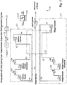
Fig. 1 is a simplified flow diagram of dual, independent expander refrigeration cycles. This figure demonstrates the independent refrigeration cycles of the invention utilizing a nitrogen stream and/or a methane stream as refrigerants. -
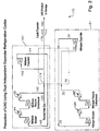
Fig. 2 is a simplified flow diagram of an another embodiment of the invention ofFig. 1 wherein a nitrogen stream and/or an inlet gas stream are used as gas phase refrigerants throughout the refrigerant cycle. -
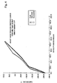
Fig. 3 is a plot of a comparison of a nitrogen warming curve and a LNG/Nitrogen cooling curves for a prior art process. -
Fig. 4 is a plot of a comparison of a refrigerant warming curve and a LNG/nitrogen/methane cooling curve for the present invention. - The present invention is directed to an improved process for the liquefaction of hydrocarbon gases, preferably a pressurized natural gas, which employs dual, independent refrigerant cycles. In a preferred embodiment, the process has a first refrigeration cycle using an expanded nitrogen refrigerant and a second refrigeration cycle using a second expanded hydrocarbon. The second expanded hydrocarbon refrigerant may be pressurized methane or treated inlet gas.
- As used herein, the term "inlet gas" will be taken to mean a hydrocarbon gas that is substantially comprised of methane, for example, 85% by volume methane, with the balance being ethane, higher hydrocarbons, nitrogen and other trace gases.
- The detailed description of preferred embodiments of this invention is made with reference to the liquefaction of a pressurized inlet gas which has an initial pressure of about 5.5 MPa (800 psia) at ambient temperature. Preferably, the inlet gas will have an initial pressure between about 3.4 MPa (500) to about 8.3 MPa (1200 psia) at ambient temperature. As discussed herein, the expanding steps, preferably by isentropic expansion, may be effectuated with a turbo-expander, Joule-Thompson expansion valves, a liquid expander or the like. Also, the expanders may be linked to corresponding staged compression units to produce compression work by gas expansion.
- Referring now to
Figure 1 of the drawings, a pressurized inlet gas stream, preferably a pressurized natural gas stream, is introduced to the process of this invention. In the embodiment illustrated, the inlet gas stream is at a pressure of about 6.2 MPa (900 psia) and ambient temperature.Inlet gas stream 11 is treated in atreatment unit 71 to removed acid gases, such as carbon dioxide, hydrogen sulfide, and the like, by known methods such as desiccation, amine extraction or the like. Also, thepretreatment unit 71 may serve as a dehydration unit of conventional design to remove water from the natural gas stream. In accordance with conventional practice in cryogenic processes, water may be removed from inlet gas streams to prevent freezing and plugging of the lines and heat exchangers at the low temperatures subsequently encountered in the process. Conventional dehydration units are used which include gas desiccants and molecular sieves. - Treated
inlet gas stream 12 may be pre-cooled via one or more unit operations. Stream 12 may be pre-cooled via cooling water in cooler 72.Stream 12 may be further pre-cooled by a conventionalmechanical refrigeration device 73 to form pre-cooled and treated stream 19 ready for liquefaction as treatedinlet gas stream 20. - Treated
inlet gas stream 20 is supplied to arefrigeration section 70 of a liquid natural gas manufacturing facility.Stream 20 is cooled and liquefied inexchanger 75 by countercurrent heat exchange contact with afirst refrigeration cycle 81 and asecond refrigeration cycle 91. These refrigeration cycles are designed to be operated independently and/or concurrently depending upon the refrigeration duty required to liquify an inlet gas stream. - In a preferred embodiment, a
first refrigeration cycle 81 uses an expanded methane refrigerant and asecond refrigeration cycle 91 uses an expanded nitrogen refrigerant. In thefirst refrigeration cycle 81, expanded methane is used as a refrigerant. A cold, expandedmethane stream 44 entersexchanger 75, preferably at about -84 °C (-119 °F) and about 1.4 MPa (200 psia) and is cross-exchanged with treatedinlet gas 20 and compressedmethane stream 40.Methane stream 44 is warmed inexchanger 75 and then enters one or more compression stages asstream 46.Warm methane stream 46 is partially compressed in a first compression stage inmethane booster compressor 92. Next,stream 46 is then compressed again in a second compression stage inmethane recycle compressor 96 to a pressure from about 3.4 MPa (500) to 9.7 MPa (1400 psia).Stream 46 is water cooled inexchangers exchanger 75 ascompressed methane stream 40.Stream 40 entersexchanger 75 at about 32 °C (90 °F) and preferably about 8.2 MPa (1185 psia).Stream 40 is cooled to about -6.7 °C (20 °F) and about 6.9 MPa (995 psia) by cross-exchange with cold, expandedmethane stream 44 and exits exchanger 75 as cooledmethane stream 42.Stream 42 is preferably isentropically expanded inexpander 90, to about -79 °C (-110) to -90 °C (-130 °F), preferably to about -84 °C (-119 °F) and about 1.4 MPa (200 psia).Stream 42 entersexchanger 75 as cold, expandedmethane stream 44. - In the
second refrigeration cycle 91, a cold, expandednitrogen stream 34 entersexchanger 75 at preferably about 162 °C (-260 °F) and about 1.4 MPa (200 psia) and is cross-exchanged with treatedinlet gas stream 20 andcompressed nitrogen stream 30.Nitrogen stream 34 is warmed inexchanger 75 and then enters one or more compression steps asstream 36.Warm nitrogen stream 36 is partially compressed innitrogen booster compressor 82 and then compressed again innitrogen recycle compressor 86 to a pressure from about 3.4 MPa (500) to 8.3 MPa (1200 psia).Stream 36 is water cooled inexchangers exchanger 75 ascompressed nitrogen stream 30.Stream 30 entersexchanger 75 at about 32 °C (90 °F) and preferably about 8.2 MPa (1185 psia).Stream 30 is cooled to preferably about -90 °C (-130 °F) and about 8.1 MPa (1180 psia) by cross-exchange with cold, expandednitrogen stream 34 and exits exchanger 75 as coolednitrogen stream 32.Stream 32 is preferably isentropically expanded inexpander 80 to about -157 °C (-250 °F) to -173 °C (-280 °F), preferably to about -162 °C (-260 °F) and about 1.4 MPa (200 psia).Stream 32 entersexchanger 75 as cold, expandednitrogen stream 34. - The first and second dual, independent refrigeration cycles work independently to cool and liquefy
inlet gas stream 20 from about -151 °C (-240) to -162 °C (-260 °F), preferably to about 159 °C (-255 °F).Liquified gas stream 22 is preferably isentropically expanded inexpander 77 to a pressure from about 100 kPa (15) to 340 kPa (50 psia), preferably to about 140 kPa (20 psia) to produce a liquifiedgas product stream 24. -
Product stream 24 may contain nitrogen and other trace gases. To remove these unwanted gases,stream 24 is introduced to anitrogen removal unit 99, such as a nitrogen stripper, to produce a treated product stream 26 and a nitrogenrich gas 27.Rich gas 27 may be used for low pressure fuel gas or recompressed and recycled with theinlet gas stream 11. - In another preferred embodiment, treated inlet gas may be used to supply at least a portion of refrigeration duty required by the process. As shown in
Fig. 2 , thefirst refrigeration cycle 191 uses an expanded hydrocarbon gas mixture as a refrigerant. The hydrocarbon gas mixture refrigerant is selected from methane, ethane and inlet gas. The second refrigeration cycle operates as discussed above. Thus, a nitrogen stream and/or an inlet gas stream are used as gas phase refrigerants throughout the refrigerant cycle. This utilizes the sensible heat of the refrigerant as the driving force for refrigeration cycle. WhileFig. 2 demonstrates the use of at least one gas phase refrigeration cycle, the refrigeration cycles are not independent from each other in that the inlet gas stream is used as a refrigerant in one cycle creating a dependence between the two refrigerant cycles. - In the
first refrigeration cycle 191, cold expandedhydrocarbon gas mixture 144 entersexchanger 75 at preferably about -84 °C (-119 °F) and 1.4 MPa (200 psia) and is cross-exchanged with aninlet gas mixture 174 to be liquified.Gas mixture stream 144 is warmed inexchanger 75 and then enters one or more compression stages asstream 146. Warmgas mixture stream 146 is partially compressed in a first compression stage inmethane booster compressor 92.Stream 146 is then compressed again in a second compression stage inmethane recycle compressor 96 to a pressure from about 3.4MPa (500) to 9.7 MPa (1400 psia).Stream 146 is water cooled inexchangers gas mixture stream 140. Preferably, treatedinlet gas 120 is mixed withcompressed gas mixture 140 to formstream 174 to be liquified. Also, treatedinlet gas 120 may be mixed withstream 146 prior to entering one or more compression stages.Stream 174 entersexchanger 75 at preferably about 32 °C (90 °F) and about 6.9 MPa (1000 psia).Stream 174 is cooled to preferably about -6.7 °C (20 °F) and about 6.9 MPa (995 psia) by cross-exchange with cold, expandedgas mixture stream 144 and exits exchanger 75 as cooledgas mixture stream 142.Stream 142 is preferably isentropically expanded inexpander 90 to about -79 °C (110) to -90 °C (-130 °F), preferably to about - 84 °C (119 °F) and about 1.4 MPa (200 psia).Stream 142 entersexchanger 75 as cold, expandedgas mixture stream 144. - The first and/or second dual refrigeration cycles work to cool and liquify
inlet gas mixture 174 from about -151 °C (-240) to -162°C (-260 °F), preferably to about -159 °C (-255 °F). Liquifiedgas mixture stream 176 is preferably isentropically expanded inexpander 77 to a pressure from about 100 kPa (15) to 340 kPa (50 psia), preferably to about 140 kPa (20 psia) to produce a liquified gasmixture product stream 180. - As noted above, the refrigerant gases in each dual refrigerant cycle may be sent to their respective booster compressors and/or recycle compressors to recompress the refrigerant. The booster compressors and/or recycle compressors may be driven by a corresponding or operably linked turbo-expander in the process. In addition, the booster compressor may be operated in post-boost mode and located downstream from the recycle compressor to supply additional compression of about 340 kPa (50) to 690 kPa (100 psia) to the refrigerant gases. The booster compressor may also be operated as pre-boosted mode and located upstream from the recycle compressor to partially compress the refrigerant gases about 340 kPa (50) to 690 kPa (100 psia) before being sent to the final recycle compressors.
-
Fig. 3 illustrates warming and cooling curves for a prior art liquefaction process. The warming curve of the nitrogen refrigerant is essentially a straight line having a slope which is adjusted by varying the circulation rate of nitrogen refrigerant until a close approximation is achieved between the warming curve of the nitrogen refrigerant and the cooling curve of the feed gas at the warm end of the exchanger. This sets the upper limit of operation of the liquefaction process. Thus, by using this prior art method it is possible to obtain relatively close approximations at both the warm and cold ends of the heat exchanger between the different curves. However, because of the different shapes of the respective curves in the intermediate portion of each it is not possible to maintain a close approximation between the two curves over the entire temperature range of the process, i.e. the two curves diverge from each other in their intermediate portions. Although the nitrogen refrigerant warming curve approximates a straight line, the cooling curve of the feed gas and nitrogen is of a complex shape and diverges markedly from the linear warming curve of the nitrogen refrigerant. The divergence between the linear warming curve and the complex cooling curve is a measure of and represents thermodynamic inefficiencies or lost work in operating the overall process. Such inefficiencies or lost work are partly responsible for the higher power consumption of using the nitrogen refrigerant cycle compared to other processes such as the mixed refrigerant cycle. -
Fig. 4 illustrates a warming and cooling curves for a preferred embodiment of this invention. This invention demonstrates improved thermodynamic efficiency or reduced lost work as compared to prior art gas liquefaction processes by utilizing the cooling capacity upon expansion of a hydrocarbon gas mixture, such as high pressure methane, ethane and/or inlet gas. In addition, thermodynamic efficiency is also improved over prior art processes because the dual refrigeration cycles and/or the dual, independent refrigeration cycles of the invention may be adjust and/or adapt to the particular refrigeration duty needed to liquefy a given inlet gas stream of known pressure, temperature and composition. That is, there is no need to supply more refrigeration duty that is required. As a result, the warming and cooling curves are more closely matched so that the temperature gradients and hence thermodynamic losses between the refrigerant and inlet gas stream are reduced. - In the process illustrated in
Fig. 1 , a simplified flow diagram of dual, independent expander refrigeration cycles is shown. This figure demonstrates the independent refrigeration cycles of the invention utilizing a nitrogen stream and/or a methane stream as refrigerants. Alternate embodiments (not shown) include the use of traditional refrigerants in one or both of the independent cycles. In the example shown inFig. 1 , the warming curve is divided into two discrete sections by splitting the refrigeration duty required to liquefy the inlet gas into two refrigeration cycles. In the first cycle, a hydrocarbon gas mixture, such as methane refrigerant is expanded, preferably in a turbo-expander, to a lower pressure at a lower temperature and provides cooling of the inlet gas stream. The second cycle is used where a nitrogen refrigerant is expanded, preferably in a turbo-expander, to a lower pressure and temperature and provides further cooling of the gas stream. The flow rate of the refrigeration in the second cycle is chosen so that the slope of the warming curve is approximately the same as that of the cooling curve. Because of the shape and slope of the cooling curves in the last portion of the cooling process, it is the nitrogen cycle that provides the major portion of the refrigeration duty in this invention. As a result, the minimum temperature approach of approximately 2.8 °C (5 °F) is achieved throughout the exchanger. - The invention has significant advantages. First, the process is adaptable to different quality of the feed inlet gas by adjusting the relationship between the nitrogen and/or gas refrigerants and thereby more thermodynamically efficient. Second, the circulating refrigerants are in the gaseous phase. This eliminates the need for liquid separators or liquid storage and the concomitant environmental safety impacts. Gas phase refrigerants simplify the heat exchanger construction and design.
Claims (17)
- A process for producing a liquefied natural gas stream from an inlet gas feed stream, the process comprising the steps of:cooling at least a portion of the inlet gas feed stream by heat exchange contact with first and second expanded refrigerants, whereby a liquefied natural gas stream is produced,characterised in that the first and second expanded refrigerants are circulated in first and second independent refrigeration cycles respectively, wherein the first and second expanded refrigerants are circulated in a gas phase such that the first and second refrigeration cycles are gas phase refrigeration cycles.
- The process of claim 1 wherein the second expanded refrigerant is nitrogen.
- The process of claim 1 or claim 2 wherein the liquefied natural gas stream is cooled to a temperature of about -150°C (-240°F) to about -162°C (-260°F).
- The process of any one of the preceding claims wherein the inlet gas stream is at an inlet pressure of about 34.47 bar (500 psia) to about 82.73 bar (1200 psia).
- The process of any one of the preceding claims wherein a cooling curve for the first and second refrigerants approaches a cooling curve for the inlet gas feed stream by at least about +5°C (5°F).
- The process of any one of the preceding claims wherein the cooling step includes cooling at least a portion of the inlet gas feed stream with a mechanical refrigeration cycle.
- The process of claim 6 wherein the mechanical refrigeration cycle includes a refrigerant selected from the group consisting of propane and propylene.
- The process of any one of the preceding claims wherein the cooling step includes cooling at least a portion of the inlet gas feed stream with cooling water.
- The process of claim 1, wherein the first refrigeration cycle is a methane refrigeration cycle, and the second refrigeration cycle is a nitrogen refrigeration cycle,
the methane refrigeration cycle comprising the steps of:expanding a first gas-phase refrigerant comprising methane to form a cold methane vapour stream;cooling at least a portion of the inlet feed gas stream by heat exchange contact with the cold refrigerant vapour stream;compressing the cold methane vapour stream to form a compressed methane vapour stream; andcooling at least a portion of the compressed methane vapour stream by heat exchange contact with the cold methane vapour stream; andthe nitrogen refrigeration cycle comprising the steps of:expanding a second gas-phase refrigerant comprising nitrogen to a cold nitrogen vapour stream;cooling at least a portion of the inlet feed gas stream by heat exchange contact with the cold nitrogen vapour stream simultaneously as cooling at least a portion of the inlet feed gas stream by heat exchange contact with the cold methane vapour stream;compressing the cold nitrogen vapour stream to form a compressed nitrogen vapour stream; andcooling at least a portion of the compressed nitrogen vapour stream by heat exchange contact with the cold nitrogen vapour stream;whereby a liquefied natural gas stream is produced. - The process of claim 9 wherein the first methane refrigeration cycle includes expanding the first gas-phase refrigerant to a temperature of about 70°C (-110°F) to about 90°C (-130°F).
- The process of claim 2 or any claim dependent thereon or any one of claims 9 or 10 wherein the nitrogen is expanded to a temperature of about 156°C (-250°F) to about 260°C (-280°F).
- The process of claim 2 or any claim dependent thereon or any one of claims 9 or 10 wherein the compressed nitrogen vapour stream of the nitrogen refrigeration cycle is compressed to a pressure of about 34-47 bar (500 psia) to about 82-73 bar (1200 psia).
- The process of claim 9 or any claim dependent thereon wherein the compressed methane vapour stream of the first methane refrigerant cycle is compressed to a pressure of about 34.47 bar (500 psia) to about 96-51 bar (1400 psia).
- The process of any one of the preceding claims further comprising the step of removing nitrogen and other trace gases from the liquefied natural gas stream.
- The process of any one of the preceding claims further comprising the step of expanding the liquefied natural gas stream to a pressure from about 1.03 bar (15 psia) to about 3.45 bar (50 psia).
- The process of claim 1, wherein the first and second expanded refrigerants remain in a gas-phase and are used in a plurality of independent turbo-expander refrigeration cycles.
- The process of claim 16, wherein the first expanded refrigerant is selected from the group consisting of methane and ethane, and the second expanded refrigerant is nitrogen.
Priority Applications (1)
| Application Number | Priority Date | Filing Date | Title |
|---|---|---|---|
| EP12152549A EP2447652A3 (en) | 2001-03-06 | 2002-03-06 | LNG production using dual independent expander refrigeration cycles |
Applications Claiming Priority (5)
| Application Number | Priority Date | Filing Date | Title |
|---|---|---|---|
| US27353101P | 2001-03-06 | 2001-03-06 | |
| US273531P | 2001-03-06 | ||
| US828551 | 2001-04-06 | ||
| US09/828,551 US6412302B1 (en) | 2001-03-06 | 2001-04-06 | LNG production using dual independent expander refrigeration cycles |
| PCT/US2002/006792 WO2002070972A2 (en) | 2001-03-06 | 2002-03-06 | Lng production using dual independent expander refrigeration cycles |
Related Child Applications (1)
| Application Number | Title | Priority Date | Filing Date |
|---|---|---|---|
| EP12152549A Division-Into EP2447652A3 (en) | 2001-03-06 | 2002-03-06 | LNG production using dual independent expander refrigeration cycles |
Publications (2)
| Publication Number | Publication Date |
|---|---|
| EP1373814A2 EP1373814A2 (en) | 2004-01-02 |
| EP1373814B1 true EP1373814B1 (en) | 2019-12-18 |
Family
ID=26956267
Family Applications (2)
| Application Number | Title | Priority Date | Filing Date |
|---|---|---|---|
| EP12152549A Withdrawn EP2447652A3 (en) | 2001-03-06 | 2002-03-06 | LNG production using dual independent expander refrigeration cycles |
| EP02713770.2A Expired - Lifetime EP1373814B1 (en) | 2001-03-06 | 2002-03-06 | Lng production using dual independent expander refrigeration cycles |
Family Applications Before (1)
| Application Number | Title | Priority Date | Filing Date |
|---|---|---|---|
| EP12152549A Withdrawn EP2447652A3 (en) | 2001-03-06 | 2002-03-06 | LNG production using dual independent expander refrigeration cycles |
Country Status (8)
| Country | Link |
|---|---|
| US (1) | US6412302B1 (en) |
| EP (2) | EP2447652A3 (en) |
| JP (2) | JP4620328B2 (en) |
| KR (1) | KR100786135B1 (en) |
| AU (1) | AU2002245599B2 (en) |
| CA (1) | CA2439981C (en) |
| NO (1) | NO335908B1 (en) |
| WO (1) | WO2002070972A2 (en) |
Families Citing this family (175)
| Publication number | Priority date | Publication date | Assignee | Title |
|---|---|---|---|---|
| US7219512B1 (en) | 2001-05-04 | 2007-05-22 | Battelle Energy Alliance, Llc | Apparatus for the liquefaction of natural gas and methods relating to same |
| US7594414B2 (en) * | 2001-05-04 | 2009-09-29 | Battelle Energy Alliance, Llc | Apparatus for the liquefaction of natural gas and methods relating to same |
| US6581409B2 (en) * | 2001-05-04 | 2003-06-24 | Bechtel Bwxt Idaho, Llc | Apparatus for the liquefaction of natural gas and methods related to same |
| US20070107465A1 (en) * | 2001-05-04 | 2007-05-17 | Battelle Energy Alliance, Llc | Apparatus for the liquefaction of gas and methods relating to same |
| US7591150B2 (en) * | 2001-05-04 | 2009-09-22 | Battelle Energy Alliance, Llc | Apparatus for the liquefaction of natural gas and methods relating to same |
| US20070137246A1 (en) * | 2001-05-04 | 2007-06-21 | Battelle Energy Alliance, Llc | Systems and methods for delivering hydrogen and separation of hydrogen from a carrier medium |
| US6889522B2 (en) * | 2002-06-06 | 2005-05-10 | Abb Lummus Global, Randall Gas Technologies | LNG floating production, storage, and offloading scheme |
| US6622519B1 (en) * | 2002-08-15 | 2003-09-23 | Velocys, Inc. | Process for cooling a product in a heat exchanger employing microchannels for the flow of refrigerant and product |
| US7014835B2 (en) * | 2002-08-15 | 2006-03-21 | Velocys, Inc. | Multi-stream microchannel device |
| US6691531B1 (en) * | 2002-10-07 | 2004-02-17 | Conocophillips Company | Driver and compressor system for natural gas liquefaction |
| US6694774B1 (en) * | 2003-02-04 | 2004-02-24 | Praxair Technology, Inc. | Gas liquefaction method using natural gas and mixed gas refrigeration |
| US7065974B2 (en) * | 2003-04-01 | 2006-06-27 | Grenfell Conrad Q | Method and apparatus for pressurizing a gas |
| US7127914B2 (en) * | 2003-09-17 | 2006-10-31 | Air Products And Chemicals, Inc. | Hybrid gas liquefaction cycle with multiple expanders |
| US6997012B2 (en) * | 2004-01-06 | 2006-02-14 | Battelle Energy Alliance, Llc | Method of Liquifying a gas |
| US7665328B2 (en) * | 2004-02-13 | 2010-02-23 | Battelle Energy Alliance, Llc | Method of producing hydrogen, and rendering a contaminated biomass inert |
| US7153489B2 (en) * | 2004-02-13 | 2006-12-26 | Battelle Energy Alliance, Llc | Method of producing hydrogen |
| US7234322B2 (en) * | 2004-02-24 | 2007-06-26 | Conocophillips Company | LNG system with warm nitrogen rejection |
| WO2006017783A1 (en) * | 2004-08-06 | 2006-02-16 | Bp Corporation North America Inc. | Natural gas liquefaction process |
| KR20090121631A (en) * | 2008-05-22 | 2009-11-26 | 삼성전자주식회사 | Semiconductor memory device, memory system and data recovery methods thereof |
| RU2406949C2 (en) * | 2005-08-09 | 2010-12-20 | Эксонмобил Апстрим Рисерч Компани | Method of liquefying natural gas |
| EP2044376A2 (en) * | 2006-07-21 | 2009-04-08 | Shell Internationale Research Maatschappij B.V. | Method and apparatus for liquefying a hydrocarbon stream |
| DE102007005098A1 (en) * | 2007-02-01 | 2008-08-07 | Linde Ag | Method for operating a refrigeration cycle |
| US8616021B2 (en) * | 2007-05-03 | 2013-12-31 | Exxonmobil Upstream Research Company | Natural gas liquefaction process |
| FR2917489A1 (en) * | 2007-06-14 | 2008-12-19 | Air Liquide | METHOD AND APPARATUS FOR CRYOGENIC SEPARATION OF METHANE RICH FLOW |
| NO329177B1 (en) * | 2007-06-22 | 2010-09-06 | Kanfa Aragon As | Process and system for forming liquid LNG |
| JP5725856B2 (en) * | 2007-08-24 | 2015-05-27 | エクソンモービル アップストリーム リサーチ カンパニー | Natural gas liquefaction process |
| US9254448B2 (en) | 2007-09-13 | 2016-02-09 | Battelle Energy Alliance, Llc | Sublimation systems and associated methods |
| US9574713B2 (en) | 2007-09-13 | 2017-02-21 | Battelle Energy Alliance, Llc | Vaporization chambers and associated methods |
| US8899074B2 (en) | 2009-10-22 | 2014-12-02 | Battelle Energy Alliance, Llc | Methods of natural gas liquefaction and natural gas liquefaction plants utilizing multiple and varying gas streams |
| US9217603B2 (en) | 2007-09-13 | 2015-12-22 | Battelle Energy Alliance, Llc | Heat exchanger and related methods |
| US8061413B2 (en) | 2007-09-13 | 2011-11-22 | Battelle Energy Alliance, Llc | Heat exchangers comprising at least one porous member positioned within a casing |
| US8555672B2 (en) * | 2009-10-22 | 2013-10-15 | Battelle Energy Alliance, Llc | Complete liquefaction methods and apparatus |
| DE102007047765A1 (en) | 2007-10-05 | 2009-04-09 | Linde Aktiengesellschaft | Liquifying a hydrocarbon-rich fraction, comprises e.g. removing unwanted components like acid gas, water and/or mercury from hydrocarbon-rich fraction and liquifying the pretreated hydrocarbon-rich fraction by using a mixture cycle |
| US20100205979A1 (en) * | 2007-11-30 | 2010-08-19 | Gentry Mark C | Integrated LNG Re-Gasification Apparatus |
| US9243842B2 (en) * | 2008-02-15 | 2016-01-26 | Black & Veatch Corporation | Combined synthesis gas separation and LNG production method and system |
| CN101981272B (en) | 2008-03-28 | 2014-06-11 | 埃克森美孚上游研究公司 | Low emission power generation and hydrocarbon recovery systems and methods |
| US9528759B2 (en) | 2008-05-08 | 2016-12-27 | Conocophillips Company | Enhanced nitrogen removal in an LNG facility |
| NO331740B1 (en) * | 2008-08-29 | 2012-03-12 | Hamworthy Gas Systems As | Method and system for optimized LNG production |
| AU2009303735B2 (en) | 2008-10-14 | 2014-06-26 | Exxonmobil Upstream Research Company | Methods and systems for controlling the products of combustion |
| FR2938903B1 (en) * | 2008-11-25 | 2013-02-08 | Technip France | PROCESS FOR PRODUCING A LIQUEFIED NATURAL GAS CURRENT SUB-COOLED FROM A NATURAL GAS CHARGE CURRENT AND ASSOCIATED INSTALLATION |
| US9151537B2 (en) * | 2008-12-19 | 2015-10-06 | Kanfa Aragon As | Method and system for producing liquefied natural gas (LNG) |
| BR112012010294A2 (en) | 2009-11-12 | 2017-11-07 | Exxonmobil Upstream Res Co | integrated system and method for the recovery of low emission hydrocarbon with energy production |
| KR101145303B1 (en) | 2010-01-04 | 2012-05-14 | 한국과학기술원 | Natural gas liquefaction method and equipment for LNG FPSO |
| US10113127B2 (en) | 2010-04-16 | 2018-10-30 | Black & Veatch Holding Company | Process for separating nitrogen from a natural gas stream with nitrogen stripping in the production of liquefied natural gas |
| DE102010020282A1 (en) * | 2010-05-12 | 2011-11-17 | Linde Aktiengesellschaft | Nitrogen separation from natural gas |
| BR112012031505A2 (en) | 2010-07-02 | 2016-11-01 | Exxonmobil Upstream Res Co | stoichiometric combustion of enriched air with exhaust gas recirculation |
| US9903271B2 (en) | 2010-07-02 | 2018-02-27 | Exxonmobil Upstream Research Company | Low emission triple-cycle power generation and CO2 separation systems and methods |
| TWI554325B (en) | 2010-07-02 | 2016-10-21 | 艾克頌美孚上游研究公司 | Low emission power generation systems and methods |
| AU2011271634B2 (en) | 2010-07-02 | 2016-01-28 | Exxonmobil Upstream Research Company | Stoichiometric combustion with exhaust gas recirculation and direct contact cooler |
| KR101037226B1 (en) * | 2010-10-26 | 2011-05-25 | 한국가스공사연구개발원 | Natural gas liquefaction process |
| US9777960B2 (en) | 2010-12-01 | 2017-10-03 | Black & Veatch Holding Company | NGL recovery from natural gas using a mixed refrigerant |
| TWI593872B (en) | 2011-03-22 | 2017-08-01 | 艾克頌美孚上游研究公司 | Integrated system and methods of generating power |
| TWI564474B (en) | 2011-03-22 | 2017-01-01 | 艾克頌美孚上游研究公司 | Integrated systems for controlling stoichiometric combustion in turbine systems and methods of generating power using the same |
| TWI563166B (en) | 2011-03-22 | 2016-12-21 | Exxonmobil Upstream Res Co | Integrated generation systems and methods for generating power |
| TWI563165B (en) | 2011-03-22 | 2016-12-21 | Exxonmobil Upstream Res Co | Power generation system and method for generating power |
| US9671160B2 (en) | 2011-10-21 | 2017-06-06 | Single Buoy Moorings Inc. | Multi nitrogen expansion process for LNG production |
| US9810050B2 (en) | 2011-12-20 | 2017-11-07 | Exxonmobil Upstream Research Company | Enhanced coal-bed methane production |
| US10139157B2 (en) | 2012-02-22 | 2018-11-27 | Black & Veatch Holding Company | NGL recovery from natural gas using a mixed refrigerant |
| US9353682B2 (en) | 2012-04-12 | 2016-05-31 | General Electric Company | Methods, systems and apparatus relating to combustion turbine power plants with exhaust gas recirculation |
| US20130277021A1 (en) | 2012-04-23 | 2013-10-24 | Lummus Technology Inc. | Cold Box Design for Core Replacement |
| US9784185B2 (en) | 2012-04-26 | 2017-10-10 | General Electric Company | System and method for cooling a gas turbine with an exhaust gas provided by the gas turbine |
| US10273880B2 (en) | 2012-04-26 | 2019-04-30 | General Electric Company | System and method of recirculating exhaust gas for use in a plurality of flow paths in a gas turbine engine |
| US10655911B2 (en) | 2012-06-20 | 2020-05-19 | Battelle Energy Alliance, Llc | Natural gas liquefaction employing independent refrigerant path |
| US9599070B2 (en) | 2012-11-02 | 2017-03-21 | General Electric Company | System and method for oxidant compression in a stoichiometric exhaust gas recirculation gas turbine system |
| US9708977B2 (en) | 2012-12-28 | 2017-07-18 | General Electric Company | System and method for reheat in gas turbine with exhaust gas recirculation |
| US9574496B2 (en) | 2012-12-28 | 2017-02-21 | General Electric Company | System and method for a turbine combustor |
| US10215412B2 (en) | 2012-11-02 | 2019-02-26 | General Electric Company | System and method for load control with diffusion combustion in a stoichiometric exhaust gas recirculation gas turbine system |
| US9631815B2 (en) | 2012-12-28 | 2017-04-25 | General Electric Company | System and method for a turbine combustor |
| US10107495B2 (en) | 2012-11-02 | 2018-10-23 | General Electric Company | Gas turbine combustor control system for stoichiometric combustion in the presence of a diluent |
| US10100741B2 (en) | 2012-11-02 | 2018-10-16 | General Electric Company | System and method for diffusion combustion with oxidant-diluent mixing in a stoichiometric exhaust gas recirculation gas turbine system |
| US9611756B2 (en) | 2012-11-02 | 2017-04-04 | General Electric Company | System and method for protecting components in a gas turbine engine with exhaust gas recirculation |
| US9869279B2 (en) | 2012-11-02 | 2018-01-16 | General Electric Company | System and method for a multi-wall turbine combustor |
| US9803865B2 (en) | 2012-12-28 | 2017-10-31 | General Electric Company | System and method for a turbine combustor |
| US10208677B2 (en) | 2012-12-31 | 2019-02-19 | General Electric Company | Gas turbine load control system |
| US9581081B2 (en) | 2013-01-13 | 2017-02-28 | General Electric Company | System and method for protecting components in a gas turbine engine with exhaust gas recirculation |
| MX2015006658A (en) | 2013-01-24 | 2015-08-10 | Exxonmobil Upstream Res Co | Liquefied natural gas production. |
| US9512759B2 (en) | 2013-02-06 | 2016-12-06 | General Electric Company | System and method for catalyst heat utilization for gas turbine with exhaust gas recirculation |
| TW201502356A (en) | 2013-02-21 | 2015-01-16 | Exxonmobil Upstream Res Co | Reducing oxygen in a gas turbine exhaust |
| US9938861B2 (en) | 2013-02-21 | 2018-04-10 | Exxonmobil Upstream Research Company | Fuel combusting method |
| RU2637609C2 (en) | 2013-02-28 | 2017-12-05 | Эксонмобил Апстрим Рисерч Компани | System and method for turbine combustion chamber |
| US20140250945A1 (en) | 2013-03-08 | 2014-09-11 | Richard A. Huntington | Carbon Dioxide Recovery |
| WO2014137648A1 (en) | 2013-03-08 | 2014-09-12 | Exxonmobil Upstream Research Company | Power generation and methane recovery from methane hydrates |
| US9618261B2 (en) | 2013-03-08 | 2017-04-11 | Exxonmobil Upstream Research Company | Power generation and LNG production |
| TW201500635A (en) | 2013-03-08 | 2015-01-01 | Exxonmobil Upstream Res Co | Processing exhaust for use in enhanced oil recovery |
| US8683823B1 (en) | 2013-03-20 | 2014-04-01 | Flng, Llc | System for offshore liquefaction |
| US8646289B1 (en) | 2013-03-20 | 2014-02-11 | Flng, Llc | Method for offshore liquefaction |
| US8640493B1 (en) | 2013-03-20 | 2014-02-04 | Flng, Llc | Method for liquefaction of natural gas offshore |
| US9631542B2 (en) | 2013-06-28 | 2017-04-25 | General Electric Company | System and method for exhausting combustion gases from gas turbine engines |
| US9617914B2 (en) | 2013-06-28 | 2017-04-11 | General Electric Company | Systems and methods for monitoring gas turbine systems having exhaust gas recirculation |
| TWI654368B (en) | 2013-06-28 | 2019-03-21 | 美商艾克頌美孚上游研究公司 | System, method and media for controlling exhaust gas flow in an exhaust gas recirculation gas turbine system |
| US9835089B2 (en) | 2013-06-28 | 2017-12-05 | General Electric Company | System and method for a fuel nozzle |
| US9903588B2 (en) | 2013-07-30 | 2018-02-27 | General Electric Company | System and method for barrier in passage of combustor of gas turbine engine with exhaust gas recirculation |
| US9587510B2 (en) | 2013-07-30 | 2017-03-07 | General Electric Company | System and method for a gas turbine engine sensor |
| US9951658B2 (en) | 2013-07-31 | 2018-04-24 | General Electric Company | System and method for an oxidant heating system |
| US20150033792A1 (en) * | 2013-07-31 | 2015-02-05 | General Electric Company | System and integrated process for liquid natural gas production |
| US10563913B2 (en) | 2013-11-15 | 2020-02-18 | Black & Veatch Holding Company | Systems and methods for hydrocarbon refrigeration with a mixed refrigerant cycle |
| US10030588B2 (en) | 2013-12-04 | 2018-07-24 | General Electric Company | Gas turbine combustor diagnostic system and method |
| US9752458B2 (en) | 2013-12-04 | 2017-09-05 | General Electric Company | System and method for a gas turbine engine |
| US10227920B2 (en) | 2014-01-15 | 2019-03-12 | General Electric Company | Gas turbine oxidant separation system |
| US9915200B2 (en) | 2014-01-21 | 2018-03-13 | General Electric Company | System and method for controlling the combustion process in a gas turbine operating with exhaust gas recirculation |
| US9863267B2 (en) | 2014-01-21 | 2018-01-09 | General Electric Company | System and method of control for a gas turbine engine |
| US10079564B2 (en) | 2014-01-27 | 2018-09-18 | General Electric Company | System and method for a stoichiometric exhaust gas recirculation gas turbine system |
| US9574822B2 (en) | 2014-03-17 | 2017-02-21 | Black & Veatch Corporation | Liquefied natural gas facility employing an optimized mixed refrigerant system |
| US10047633B2 (en) | 2014-05-16 | 2018-08-14 | General Electric Company | Bearing housing |
| US10655542B2 (en) | 2014-06-30 | 2020-05-19 | General Electric Company | Method and system for startup of gas turbine system drive trains with exhaust gas recirculation |
| US10060359B2 (en) | 2014-06-30 | 2018-08-28 | General Electric Company | Method and system for combustion control for gas turbine system with exhaust gas recirculation |
| US9885290B2 (en) | 2014-06-30 | 2018-02-06 | General Electric Company | Erosion suppression system and method in an exhaust gas recirculation gas turbine system |
| DE102014012316A1 (en) | 2014-08-19 | 2016-02-25 | Linde Aktiengesellschaft | Process for cooling a hydrocarbon-rich fraction |
| US9869247B2 (en) | 2014-12-31 | 2018-01-16 | General Electric Company | Systems and methods of estimating a combustion equivalence ratio in a gas turbine with exhaust gas recirculation |
| US9819292B2 (en) | 2014-12-31 | 2017-11-14 | General Electric Company | Systems and methods to respond to grid overfrequency events for a stoichiometric exhaust recirculation gas turbine |
| US10788212B2 (en) | 2015-01-12 | 2020-09-29 | General Electric Company | System and method for an oxidant passageway in a gas turbine system with exhaust gas recirculation |
| US10253690B2 (en) | 2015-02-04 | 2019-04-09 | General Electric Company | Turbine system with exhaust gas recirculation, separation and extraction |
| US10316746B2 (en) | 2015-02-04 | 2019-06-11 | General Electric Company | Turbine system with exhaust gas recirculation, separation and extraction |
| US10094566B2 (en) | 2015-02-04 | 2018-10-09 | General Electric Company | Systems and methods for high volumetric oxidant flow in gas turbine engine with exhaust gas recirculation |
| US10267270B2 (en) | 2015-02-06 | 2019-04-23 | General Electric Company | Systems and methods for carbon black production with a gas turbine engine having exhaust gas recirculation |
| US10145269B2 (en) | 2015-03-04 | 2018-12-04 | General Electric Company | System and method for cooling discharge flow |
| US10480792B2 (en) | 2015-03-06 | 2019-11-19 | General Electric Company | Fuel staging in a gas turbine engine |
| US9863697B2 (en) | 2015-04-24 | 2018-01-09 | Air Products And Chemicals, Inc. | Integrated methane refrigeration system for liquefying natural gas |
| TWI641789B (en) | 2015-07-10 | 2018-11-21 | 艾克頌美孚上游研究公司 | System and methods for the production of liquefied nitrogen gas using liquefied natural gas |
| TWI608206B (en) | 2015-07-15 | 2017-12-11 | 艾克頌美孚上游研究公司 | Increasing efficiency in an lng production system by pre-cooling a natural gas feed stream |
| TWI606221B (en) | 2015-07-15 | 2017-11-21 | 艾克頌美孚上游研究公司 | Liquefied natural gas production system and method with greenhouse gas removal |
| US20170038134A1 (en) * | 2015-08-06 | 2017-02-09 | L'air Liquide, Societe Anonyme Pour L'etude Et L'exploitation Des Procedes Georges Claude | Method for the production of liquefied natural gas |
| US10563914B2 (en) | 2015-08-06 | 2020-02-18 | L'air Liquide Societe Anonyme Pour L'etude Et L'exploitation Des Procedes Georges Claude | Methods and systems for integration of industrial site efficiency losses to produce LNG and/or LIN |
| US20170038138A1 (en) * | 2015-08-06 | 2017-02-09 | L'air Liquide, Societe Anonyme Pour I'etude Et I'exploitation Des Procedes Georges Claude | Apparatus for the production of liquefied natural gas |
| JP6800977B2 (en) | 2015-12-14 | 2020-12-16 | エクソンモービル アップストリーム リサーチ カンパニー | Precooling of natural gas by high pressure compression and expansion |
| CN108369060B (en) | 2015-12-14 | 2020-06-19 | 埃克森美孚上游研究公司 | Expander-based LNG production process enhanced with liquid nitrogen |
| CN108369061B (en) | 2015-12-14 | 2020-05-22 | 埃克森美孚上游研究公司 | Method and system for separating nitrogen from liquefied natural gas using liquefied nitrogen |
| WO2017105681A1 (en) | 2015-12-14 | 2017-06-22 | Exxonmobil Upstream Research Company | Method of natural gas liquefaction on lng carriers storing liquid nitrogen |
| WO2017121751A1 (en) * | 2016-01-12 | 2017-07-20 | Global Lng Services As | Method and plant for liquefaction of pre-processed natural gas |
| FR3053771B1 (en) | 2016-07-06 | 2019-07-19 | Saipem S.P.A. | METHOD FOR LIQUEFACTING NATURAL GAS AND RECOVERING LIQUID EVENTS OF NATURAL GAS COMPRISING TWO NATURAL GAS SEMI-OPENING REFRIGERANT CYCLES AND A REFRIGERANT GAS REFRIGERANT CYCLE |
| US10634425B2 (en) | 2016-08-05 | 2020-04-28 | L'air Liquide, Societe Anonyme Pour L'etude Et L'exploitation Des Procedes Georges Claude | Integration of industrial gas site with liquid hydrogen production |
| US10393431B2 (en) | 2016-08-05 | 2019-08-27 | L'air Liquide Societe Anonyme Pour L'etude Et L'exploitation Des Procedes Georges Claude | Method for the integration of liquefied natural gas and syngas production |
| US10288346B2 (en) | 2016-08-05 | 2019-05-14 | L'air Liquide Societe Anonyme Pour L'etude Et L'exploitation Des Procedes Georges Claude | Method for liquefaction of industrial gas by integration of methanol plant and air separation unit |
| US10281203B2 (en) | 2016-08-05 | 2019-05-07 | L'air Liquide Societe Anonyme Pour L'etude Et L'exploitation Des Procedes Georges Claude | Method for liquefaction of industrial gas by integration of methanol plant and air separation unit |
| WO2018096580A1 (en) * | 2016-11-22 | 2018-05-31 | 三菱電機株式会社 | Refrigeration cycle device |
| US20180231303A1 (en) | 2017-02-13 | 2018-08-16 | Fritz Pierre, JR. | Pre-Cooling of Natural Gas by High Pressure Compression and Expansion |
| US11402151B2 (en) | 2017-02-24 | 2022-08-02 | Praxair Technology, Inc. | Liquid natural gas liquefier utilizing mechanical and liquid nitrogen refrigeration |
| SG11201906786YA (en) | 2017-02-24 | 2019-09-27 | Exxonmobil Upstream Res Co | Method of purging a dual purpose lng/lin storage tank |
| RU2645185C1 (en) * | 2017-03-16 | 2018-02-16 | Публичное акционерное общество "НОВАТЭК" | Method of natural gas liquefaction by the cycle of high pressure with the precooling of ethane and nitrogen "arctic cascade" and the installation for its implementation |
| US20230266059A1 (en) * | 2017-05-12 | 2023-08-24 | Samsung Heavy Ind. Co., Ltd | Natural gas liquefaction apparatus |
| KR102039618B1 (en) * | 2017-05-12 | 2019-11-01 | 삼성중공업(주) | Natural Gas Liquefaction Apparatus |
| CN110869686B (en) * | 2017-07-07 | 2021-07-30 | 全球As液化天然气服务 | Large scale coastal liquefaction |
| EP3688391A1 (en) | 2017-09-29 | 2020-08-05 | ExxonMobil Upstream Research Company | Natural gas liquefaction by a high pressure expansion process |
| JP6945732B2 (en) * | 2017-09-29 | 2021-10-06 | エクソンモービル アップストリーム リサーチ カンパニー | Natural gas liquefaction by high-pressure expansion process |
| AU2018354587B2 (en) | 2017-10-25 | 2022-02-17 | Exxonmobil Upstream Research Company | Natural gas liquefaction by a high pressure expansion process using multiple turboexpander compressors |
| US10866022B2 (en) | 2018-04-27 | 2020-12-15 | Air Products And Chemicals, Inc. | Method and system for cooling a hydrocarbon stream using a gas phase refrigerant |
| US10788261B2 (en) | 2018-04-27 | 2020-09-29 | Air Products And Chemicals, Inc. | Method and system for cooling a hydrocarbon stream using a gas phase refrigerant |
| EP3803241B1 (en) | 2018-06-07 | 2022-09-28 | ExxonMobil Upstream Research Company | Pretreatment and pre-cooling of natural gas by high pressure compression and expansion |
| US11009291B2 (en) * | 2018-06-28 | 2021-05-18 | Global Lng Services As | Method for air cooled, large scale, floating LNG production with liquefaction gas as only refrigerant |
| KR102106621B1 (en) | 2018-07-31 | 2020-05-28 | 삼성중공업 주식회사 | Boil-Off Gas liquefaction system and liquefaction method |
| US11326834B2 (en) | 2018-08-14 | 2022-05-10 | Exxonmobil Upstream Research Company | Conserving mixed refrigerant in natural gas liquefaction facilities |
| SG11202101054SA (en) * | 2018-08-22 | 2021-03-30 | Exxonmobil Upstream Res Co | Primary loop start-up method for a high pressure expander process |
| SG11202101058QA (en) | 2018-08-22 | 2021-03-30 | Exxonmobil Upstream Res Co | Heat exchanger configuration for a high pressure expander process and a method of natural gas liquefaction using the same |
| AU2019326291B9 (en) | 2018-08-22 | 2023-04-13 | ExxonMobil Technology and Engineering Company | Managing make-up gas composition variation for a high pressure expander process |
| US11578545B2 (en) | 2018-11-20 | 2023-02-14 | Exxonmobil Upstream Research Company | Poly refrigerated integrated cycle operation using solid-tolerant heat exchangers |
| WO2020106397A1 (en) | 2018-11-20 | 2020-05-28 | Exxonmobil Upstream Research Company | Methods and apparatus for improving multi-plate scraped heat exchangers |
| US11668524B2 (en) | 2019-01-30 | 2023-06-06 | Exxonmobil Upstream Research Company | Methods for removal of moisture from LNG refrigerant |
| JP2022517930A (en) | 2019-01-30 | 2022-03-11 | エクソンモービル アップストリーム リサーチ カンパニー | Moisture removal method from LNG refrigerant |
| WO2020245510A1 (en) | 2019-06-04 | 2020-12-10 | Total Se | Installation for producing lng from natural gas, floating support integrating such an installation, and corresponding method |
| US11465093B2 (en) | 2019-08-19 | 2022-10-11 | Exxonmobil Upstream Research Company | Compliant composite heat exchangers |
| US20210063083A1 (en) | 2019-08-29 | 2021-03-04 | Exxonmobil Upstream Research Company | Liquefaction of Production Gas |
| US20210088274A1 (en) | 2019-09-19 | 2021-03-25 | Exxonmobil Upstream Research Company | Pretreatment, Pre-Cooling, and Condensate Recovery of Natural Gas By High Pressure Compression and Expansion |
| WO2021055021A1 (en) | 2019-09-19 | 2021-03-25 | Exxonmobil Upstream Research Company | Pretreatment and pre-cooling of natural gas by high pressure compression and expansion |
| US11806639B2 (en) | 2019-09-19 | 2023-11-07 | ExxonMobil Technology and Engineering Company | Pretreatment and pre-cooling of natural gas by high pressure compression and expansion |
| WO2021055074A1 (en) | 2019-09-20 | 2021-03-25 | Exxonmobil Upstream Research Company | Removal of acid gases from a gas stream, with o2 enrichment for acid gas capture and sequestration |
| JP2022548529A (en) | 2019-09-24 | 2022-11-21 | エクソンモービル アップストリーム リサーチ カンパニー | Cargo stripping capabilities for dual-purpose cryogenic tanks on ships or floating storage units for LNG and liquid nitrogen |
| WO2022099233A1 (en) | 2020-11-03 | 2022-05-12 | Exxonmobil Upstream Research Company | Natural gas liquefaction methods and systems featuring feed compression, expansion and recycling |
| IT202000026978A1 (en) * | 2020-11-11 | 2022-05-11 | Saipem Spa | INTEGRATED PROCESS FOR PURIFICATION AND LIQUEFACTION OF NATURAL GAS |
| WO2022147385A1 (en) | 2020-12-29 | 2022-07-07 | Exxonmobil Upstream Research Company | Natural gas liquefaction methods and systems featuring secondary liquid cooling |
| US20220333852A1 (en) | 2021-04-15 | 2022-10-20 | Henry Edward Howard | System and method to produce liquefied natural gas using two distinct refrigeration cycles with an integral gear machine |
| US20220333854A1 (en) | 2021-04-15 | 2022-10-20 | Henry Edward Howard | System and method to produce liquefied natural gas using two distinct refrigeration cycles with an integral gear machine |
| US20220333856A1 (en) | 2021-04-15 | 2022-10-20 | Henry Edward Howard | System and method to produce liquefied natural gas using two distinct refrigeration cycles with an integral gear machine |
| US20220333855A1 (en) | 2021-04-15 | 2022-10-20 | Henry Edward Howard | System and method to produce liquefied natural gas using two distinct refrigeration cycles with an integral gear machine |
| US20220333858A1 (en) | 2021-04-15 | 2022-10-20 | Henry Edward Howard | System and method to produce liquefied natural gas using two distinct refrigeration cycles with an integral gear machine |
| US20220333853A1 (en) | 2021-04-16 | 2022-10-20 | Henry Edward Howard | System and method to produce liquefied natural gas using a three pinion integral gear machine |
Family Cites Families (17)
| Publication number | Priority date | Publication date | Assignee | Title |
|---|---|---|---|---|
| US4057972A (en) * | 1973-09-14 | 1977-11-15 | Exxon Research & Engineering Co. | Fractional condensation of an NG feed with two independent refrigeration cycles |
| DE2440215A1 (en) * | 1974-08-22 | 1976-03-04 | Linde Ag | Liquefaction of low-boiling gases - by partial liquefaction with mixed liquid coolant and further cooling with expanded gas coolant |
| US4461634A (en) * | 1980-10-16 | 1984-07-24 | Petrocarbon Developments Limited | Separation of gas mixtures by partial condensation |
| IT1176290B (en) * | 1984-06-12 | 1987-08-18 | Snam Progetti | LOW-BOILING GAS COOLING AND LIQUEFATION PROCESS |
| US4755200A (en) * | 1987-02-27 | 1988-07-05 | Air Products And Chemicals, Inc. | Feed gas drier precooling in mixed refrigerant natural gas liquefaction processes |
| US4911741A (en) * | 1988-09-23 | 1990-03-27 | Davis Robert N | Natural gas liquefaction process using low level high level and absorption refrigeration cycles |
| US5036671A (en) * | 1990-02-06 | 1991-08-06 | Liquid Air Engineering Company | Method of liquefying natural gas |
| FR2714722B1 (en) * | 1993-12-30 | 1997-11-21 | Inst Francais Du Petrole | Method and apparatus for liquefying a natural gas. |
| AUPM485694A0 (en) | 1994-04-05 | 1994-04-28 | Bhp Petroleum Pty. Ltd. | Liquefaction process |
| MY113626A (en) | 1995-10-05 | 2002-04-30 | Bhp Petroleum Pty Ltd | Liquefaction apparatus |
| FR2743140B1 (en) * | 1995-12-28 | 1998-01-23 | Inst Francais Du Petrole | METHOD AND DEVICE FOR TWO-STEP LIQUEFACTION OF A GAS MIXTURE SUCH AS A NATURAL GAS |
| US5755114A (en) * | 1997-01-06 | 1998-05-26 | Abb Randall Corporation | Use of a turboexpander cycle in liquefied natural gas process |
| DZ2534A1 (en) * | 1997-06-20 | 2003-02-08 | Exxon Production Research Co | Improved cascade refrigeration process for liquefying natural gas. |
| FR2764972B1 (en) * | 1997-06-24 | 1999-07-16 | Inst Francais Du Petrole | METHOD FOR LIQUEFACTING A NATURAL GAS WITH TWO INTERCONNECTED STAGES |
| FR2778232B1 (en) * | 1998-04-29 | 2000-06-02 | Inst Francais Du Petrole | METHOD AND DEVICE FOR LIQUEFACTION OF A NATURAL GAS WITHOUT SEPARATION OF PHASES ON THE REFRIGERANT MIXTURES |
| US6308531B1 (en) * | 1999-10-12 | 2001-10-30 | Air Products And Chemicals, Inc. | Hybrid cycle for the production of liquefied natural gas |
| MY122625A (en) * | 1999-12-17 | 2006-04-29 | Exxonmobil Upstream Res Co | Process for making pressurized liquefied natural gas from pressured natural gas using expansion cooling |
-
2001
- 2001-04-06 US US09/828,551 patent/US6412302B1/en not_active Expired - Lifetime
-
2002
- 2002-03-06 EP EP12152549A patent/EP2447652A3/en not_active Withdrawn
- 2002-03-06 CA CA2439981A patent/CA2439981C/en not_active Expired - Lifetime
- 2002-03-06 WO PCT/US2002/006792 patent/WO2002070972A2/en active IP Right Grant
- 2002-03-06 KR KR1020037011582A patent/KR100786135B1/en active IP Right Grant
- 2002-03-06 JP JP2002569650A patent/JP4620328B2/en not_active Expired - Lifetime
- 2002-03-06 AU AU2002245599A patent/AU2002245599B2/en not_active Ceased
- 2002-03-06 EP EP02713770.2A patent/EP1373814B1/en not_active Expired - Lifetime
-
2003
- 2003-09-02 NO NO20033873A patent/NO335908B1/en not_active IP Right Cessation
-
2010
- 2010-07-30 JP JP2010171738A patent/JP5960945B2/en not_active Expired - Lifetime
Non-Patent Citations (1)
| Title |
|---|
| None * |
Also Published As
| Publication number | Publication date |
|---|---|
| WO2002070972A2 (en) | 2002-09-12 |
| NO335908B1 (en) | 2015-03-23 |
| AU2002245599B2 (en) | 2007-04-26 |
| WO2002070972A3 (en) | 2003-10-16 |
| EP2447652A2 (en) | 2012-05-02 |
| JP4620328B2 (en) | 2011-01-26 |
| KR100786135B1 (en) | 2007-12-21 |
| EP2447652A3 (en) | 2012-06-27 |
| JP2004532295A (en) | 2004-10-21 |
| CA2439981C (en) | 2010-11-09 |
| US6412302B1 (en) | 2002-07-02 |
| NO20033873L (en) | 2003-10-31 |
| JP5960945B2 (en) | 2016-08-02 |
| NO20033873D0 (en) | 2003-09-02 |
| EP1373814A2 (en) | 2004-01-02 |
| CA2439981A1 (en) | 2002-09-12 |
| JP2011001554A (en) | 2011-01-06 |
| KR20030082954A (en) | 2003-10-23 |
Similar Documents
| Publication | Publication Date | Title |
|---|---|---|
| EP1373814B1 (en) | Lng production using dual independent expander refrigeration cycles | |
| AU2002245599A1 (en) | LNG production using dual independent expander refrigeration cycles | |
| KR100438079B1 (en) | Method and apparatus for the liquefaction of a feed gas | |
| AU777060B2 (en) | Process for liquefying natural gas by expansion cooling | |
| JP3511004B2 (en) | Source gas liquefaction method | |
| US7127914B2 (en) | Hybrid gas liquefaction cycle with multiple expanders | |
| US5768912A (en) | Liquefaction process | |
| AU2008208879B2 (en) | Method and apparatus for cooling a hydrocarbon stream | |
| JP5107896B2 (en) | Natural gas stream liquefaction method and apparatus | |
| AU2009239763B2 (en) | Dual nitrogen expansion process | |
| US20030177785A1 (en) | Process for producing a pressurized liquefied gas product by cooling and expansion of a gas stream in the supercritical state | |
| EP3561421B1 (en) | Improved method and system for cooling a hydrocarbon stream using a gas phase refrigerant | |
| AU681954B2 (en) | Liquefaction process |
Legal Events
| Date | Code | Title | Description |
|---|---|---|---|
| PUAI | Public reference made under article 153(3) epc to a published international application that has entered the european phase |
Free format text: ORIGINAL CODE: 0009012 |
|
| 17P | Request for examination filed |
Effective date: 20030929 |
|
| AK | Designated contracting states |
Kind code of ref document: A2 Designated state(s): AT BE CH CY DE DK ES FI FR GB GR IE IT LI LU MC NL PT SE TR |
|
| AX | Request for extension of the european patent |
Extension state: AL LT LV MK RO SI |
|
| RAP1 | Party data changed (applicant data changed or rights of an application transferred) |
Owner name: LUMMUS TECHNOLOGY INC. |
|
| 17Q | First examination report despatched |
Effective date: 20100127 |
|
| TPAC | Observations filed by third parties |
Free format text: ORIGINAL CODE: EPIDOSNTIPA |
|
| STAA | Information on the status of an ep patent application or granted ep patent |
Free format text: STATUS: EXAMINATION IS IN PROGRESS |
|
| GRAP | Despatch of communication of intention to grant a patent |
Free format text: ORIGINAL CODE: EPIDOSNIGR1 |
|
| STAA | Information on the status of an ep patent application or granted ep patent |
Free format text: STATUS: GRANT OF PATENT IS INTENDED |
|
| INTG | Intention to grant announced |
Effective date: 20190726 |
|
| GRAS | Grant fee paid |
Free format text: ORIGINAL CODE: EPIDOSNIGR3 |
|
| GRAA | (expected) grant |
Free format text: ORIGINAL CODE: 0009210 |
|
| STAA | Information on the status of an ep patent application or granted ep patent |
Free format text: STATUS: THE PATENT HAS BEEN GRANTED |
|
| AK | Designated contracting states |
Kind code of ref document: B1 Designated state(s): AT BE CH CY DE DK ES FI FR GB GR IE IT LI LU MC NL PT SE TR |
|
| REG | Reference to a national code |
Ref country code: GB Ref legal event code: FG4D |
|
| REG | Reference to a national code |
Ref country code: CH Ref legal event code: EP |
|
| REG | Reference to a national code |
Ref country code: IE Ref legal event code: FG4D |
|
| REG | Reference to a national code |
Ref country code: DE Ref legal event code: R096 Ref document number: 60250067 Country of ref document: DE |
|
| REG | Reference to a national code |
Ref country code: AT Ref legal event code: REF Ref document number: 1215064 Country of ref document: AT Kind code of ref document: T Effective date: 20200115 |
|
| REG | Reference to a national code |
Ref country code: NL Ref legal event code: FP |
|
| PG25 | Lapsed in a contracting state [announced via postgrant information from national office to epo] |
Ref country code: FI Free format text: LAPSE BECAUSE OF FAILURE TO SUBMIT A TRANSLATION OF THE DESCRIPTION OR TO PAY THE FEE WITHIN THE PRESCRIBED TIME-LIMIT Effective date: 20191218 Ref country code: SE Free format text: LAPSE BECAUSE OF FAILURE TO SUBMIT A TRANSLATION OF THE DESCRIPTION OR TO PAY THE FEE WITHIN THE PRESCRIBED TIME-LIMIT Effective date: 20191218 Ref country code: GR Free format text: LAPSE BECAUSE OF FAILURE TO SUBMIT A TRANSLATION OF THE DESCRIPTION OR TO PAY THE FEE WITHIN THE PRESCRIBED TIME-LIMIT Effective date: 20200319 |
|
| PGFP | Annual fee paid to national office [announced via postgrant information from national office to epo] |
Ref country code: NL Payment date: 20200312 Year of fee payment: 19 Ref country code: GB Payment date: 20200311 Year of fee payment: 19 Ref country code: DE Payment date: 20200325 Year of fee payment: 19 |
|
| PGFP | Annual fee paid to national office [announced via postgrant information from national office to epo] |
Ref country code: FR Payment date: 20200312 Year of fee payment: 19 |
|
| PG25 | Lapsed in a contracting state [announced via postgrant information from national office to epo] |
Ref country code: PT Free format text: LAPSE BECAUSE OF FAILURE TO SUBMIT A TRANSLATION OF THE DESCRIPTION OR TO PAY THE FEE WITHIN THE PRESCRIBED TIME-LIMIT Effective date: 20200513 |
|
| REG | Reference to a national code |
Ref country code: DE Ref legal event code: R097 Ref document number: 60250067 Country of ref document: DE |
|
| REG | Reference to a national code |
Ref country code: AT Ref legal event code: MK05 Ref document number: 1215064 Country of ref document: AT Kind code of ref document: T Effective date: 20191218 |
|
| PLBE | No opposition filed within time limit |
Free format text: ORIGINAL CODE: 0009261 |
|
| STAA | Information on the status of an ep patent application or granted ep patent |
Free format text: STATUS: NO OPPOSITION FILED WITHIN TIME LIMIT |
|
| PG25 | Lapsed in a contracting state [announced via postgrant information from national office to epo] |
Ref country code: DK Free format text: LAPSE BECAUSE OF FAILURE TO SUBMIT A TRANSLATION OF THE DESCRIPTION OR TO PAY THE FEE WITHIN THE PRESCRIBED TIME-LIMIT Effective date: 20191218 Ref country code: MC Free format text: LAPSE BECAUSE OF FAILURE TO SUBMIT A TRANSLATION OF THE DESCRIPTION OR TO PAY THE FEE WITHIN THE PRESCRIBED TIME-LIMIT Effective date: 20191218 Ref country code: ES Free format text: LAPSE BECAUSE OF FAILURE TO SUBMIT A TRANSLATION OF THE DESCRIPTION OR TO PAY THE FEE WITHIN THE PRESCRIBED TIME-LIMIT Effective date: 20191218 |
|
| REG | Reference to a national code |
Ref country code: CH Ref legal event code: PL |
|
| 26N | No opposition filed |
Effective date: 20200921 |
|
| PG25 | Lapsed in a contracting state [announced via postgrant information from national office to epo] |
Ref country code: AT Free format text: LAPSE BECAUSE OF FAILURE TO SUBMIT A TRANSLATION OF THE DESCRIPTION OR TO PAY THE FEE WITHIN THE PRESCRIBED TIME-LIMIT Effective date: 20191218 |
|
| REG | Reference to a national code |
Ref country code: BE Ref legal event code: MM Effective date: 20200331 |
|
| PG25 | Lapsed in a contracting state [announced via postgrant information from national office to epo] |
Ref country code: LU Free format text: LAPSE BECAUSE OF NON-PAYMENT OF DUE FEES Effective date: 20200306 |
|
| PG25 | Lapsed in a contracting state [announced via postgrant information from national office to epo] |
Ref country code: LI Free format text: LAPSE BECAUSE OF NON-PAYMENT OF DUE FEES Effective date: 20200331 Ref country code: IT Free format text: LAPSE BECAUSE OF FAILURE TO SUBMIT A TRANSLATION OF THE DESCRIPTION OR TO PAY THE FEE WITHIN THE PRESCRIBED TIME-LIMIT Effective date: 20191218 Ref country code: CH Free format text: LAPSE BECAUSE OF NON-PAYMENT OF DUE FEES Effective date: 20200331 Ref country code: IE Free format text: LAPSE BECAUSE OF NON-PAYMENT OF DUE FEES Effective date: 20200306 |
|
| PG25 | Lapsed in a contracting state [announced via postgrant information from national office to epo] |
Ref country code: BE Free format text: LAPSE BECAUSE OF NON-PAYMENT OF DUE FEES Effective date: 20200331 |
|
| REG | Reference to a national code |
Ref country code: DE Ref legal event code: R119 Ref document number: 60250067 Country of ref document: DE |
|
| REG | Reference to a national code |
Ref country code: NL Ref legal event code: MM Effective date: 20210401 |
|
| GBPC | Gb: european patent ceased through non-payment of renewal fee |
Effective date: 20210306 |
|
| PG25 | Lapsed in a contracting state [announced via postgrant information from national office to epo] |
Ref country code: NL Free format text: LAPSE BECAUSE OF NON-PAYMENT OF DUE FEES Effective date: 20210401 Ref country code: DE Free format text: LAPSE BECAUSE OF NON-PAYMENT OF DUE FEES Effective date: 20211001 Ref country code: FR Free format text: LAPSE BECAUSE OF NON-PAYMENT OF DUE FEES Effective date: 20210331 Ref country code: GB Free format text: LAPSE BECAUSE OF NON-PAYMENT OF DUE FEES Effective date: 20210306 |
|
| PG25 | Lapsed in a contracting state [announced via postgrant information from national office to epo] |
Ref country code: TR Free format text: LAPSE BECAUSE OF FAILURE TO SUBMIT A TRANSLATION OF THE DESCRIPTION OR TO PAY THE FEE WITHIN THE PRESCRIBED TIME-LIMIT Effective date: 20191218 Ref country code: CY Free format text: LAPSE BECAUSE OF FAILURE TO SUBMIT A TRANSLATION OF THE DESCRIPTION OR TO PAY THE FEE WITHIN THE PRESCRIBED TIME-LIMIT Effective date: 20191218 |