EP1372501B1 - Occiputplatte und system zur stabilisierung der wirbelsäule - Google Patents
Occiputplatte und system zur stabilisierung der wirbelsäule Download PDFInfo
- Publication number
- EP1372501B1 EP1372501B1 EP02714963A EP02714963A EP1372501B1 EP 1372501 B1 EP1372501 B1 EP 1372501B1 EP 02714963 A EP02714963 A EP 02714963A EP 02714963 A EP02714963 A EP 02714963A EP 1372501 B1 EP1372501 B1 EP 1372501B1
- Authority
- EP
- European Patent Office
- Prior art keywords
- plate
- occipital plate
- occipital
- disposed
- hole
- Prior art date
- Legal status (The legal status is an assumption and is not a legal conclusion. Google has not performed a legal analysis and makes no representation as to the accuracy of the status listed.)
- Expired - Lifetime
Links
Images


Classifications
-
- A—HUMAN NECESSITIES
- A61—MEDICAL OR VETERINARY SCIENCE; HYGIENE
- A61B—DIAGNOSIS; SURGERY; IDENTIFICATION
- A61B17/00—Surgical instruments, devices or methods, e.g. tourniquets
- A61B17/56—Surgical instruments or methods for treatment of bones or joints; Devices specially adapted therefor
- A61B17/58—Surgical instruments or methods for treatment of bones or joints; Devices specially adapted therefor for osteosynthesis, e.g. bone plates, screws, setting implements or the like
- A61B17/68—Internal fixation devices, including fasteners and spinal fixators, even if a part thereof projects from the skin
- A61B17/70—Spinal positioners or stabilisers ; Bone stabilisers comprising fluid filler in an implant
- A61B17/7055—Spinal positioners or stabilisers ; Bone stabilisers comprising fluid filler in an implant connected to sacrum, pelvis or skull
-
- A—HUMAN NECESSITIES
- A61—MEDICAL OR VETERINARY SCIENCE; HYGIENE
- A61B—DIAGNOSIS; SURGERY; IDENTIFICATION
- A61B17/00—Surgical instruments, devices or methods, e.g. tourniquets
- A61B17/56—Surgical instruments or methods for treatment of bones or joints; Devices specially adapted therefor
- A61B17/58—Surgical instruments or methods for treatment of bones or joints; Devices specially adapted therefor for osteosynthesis, e.g. bone plates, screws, setting implements or the like
- A61B17/68—Internal fixation devices, including fasteners and spinal fixators, even if a part thereof projects from the skin
- A61B17/70—Spinal positioners or stabilisers ; Bone stabilisers comprising fluid filler in an implant
- A61B17/7001—Screws or hooks combined with longitudinal elements which do not contact vertebrae
- A61B17/7002—Longitudinal elements, e.g. rods
- A61B17/7011—Longitudinal element being non-straight, e.g. curved, angled or branched
-
- A—HUMAN NECESSITIES
- A61—MEDICAL OR VETERINARY SCIENCE; HYGIENE
- A61B—DIAGNOSIS; SURGERY; IDENTIFICATION
- A61B17/00—Surgical instruments, devices or methods, e.g. tourniquets
- A61B17/56—Surgical instruments or methods for treatment of bones or joints; Devices specially adapted therefor
- A61B17/58—Surgical instruments or methods for treatment of bones or joints; Devices specially adapted therefor for osteosynthesis, e.g. bone plates, screws, setting implements or the like
- A61B17/68—Internal fixation devices, including fasteners and spinal fixators, even if a part thereof projects from the skin
- A61B17/80—Cortical plates, i.e. bone plates; Instruments for holding or positioning cortical plates, or for compressing bones attached to cortical plates
- A61B17/8033—Cortical plates, i.e. bone plates; Instruments for holding or positioning cortical plates, or for compressing bones attached to cortical plates having indirect contact with screw heads, or having contact with screw heads maintained with the aid of additional components, e.g. nuts, wedges or head covers
- A61B17/8047—Cortical plates, i.e. bone plates; Instruments for holding or positioning cortical plates, or for compressing bones attached to cortical plates having indirect contact with screw heads, or having contact with screw heads maintained with the aid of additional components, e.g. nuts, wedges or head covers wherein the additional element surrounds the screw head in the plate hole
-
- A—HUMAN NECESSITIES
- A61—MEDICAL OR VETERINARY SCIENCE; HYGIENE
- A61B—DIAGNOSIS; SURGERY; IDENTIFICATION
- A61B17/00—Surgical instruments, devices or methods, e.g. tourniquets
- A61B17/56—Surgical instruments or methods for treatment of bones or joints; Devices specially adapted therefor
- A61B17/58—Surgical instruments or methods for treatment of bones or joints; Devices specially adapted therefor for osteosynthesis, e.g. bone plates, screws, setting implements or the like
- A61B17/68—Internal fixation devices, including fasteners and spinal fixators, even if a part thereof projects from the skin
- A61B17/80—Cortical plates, i.e. bone plates; Instruments for holding or positioning cortical plates, or for compressing bones attached to cortical plates
- A61B17/8085—Cortical plates, i.e. bone plates; Instruments for holding or positioning cortical plates, or for compressing bones attached to cortical plates with pliable or malleable elements or having a mesh-like structure, e.g. small strips
Definitions
- the present invention is related to a system for stabilizing the spine. More particularly, the present invention is related to an occipitocervical fixation system that is mounted to both the occiput and spine.
- Occipitocervical fixation has been achieved using a variety of techniques which generally provide stabilization of the base of the skull with respect to the neck.
- bone struts formed of autogenous ribs or curved iliac crest struts have been fixed to the occiput and spinous processes, cervical laminae, or facets. Wires are used to fix the struts in place until bone fusion occurs.
- the thickness of the occiput varies, however, and thus the occiput is typically wired in regions of greater thickness such as near the foramen magnum, at the nuchal line, and along the midline crest.
- Holes are drilled in the occiput to receive the wires that are also fed through holes in the struts.
- the struts may be weak prior to fusion, and additional orthosis is applied such as with a halo vest or other hard collar until the struts can provide acceptably strong immobilization.
- metal struts may be used.
- One metal implant is a stainless steel, U-shaped device known as a Steinman pin.
- the threaded pin is bent to match the contour of the occipitocervical region, and fixed to the occiput and cervical laminae or facets using wires.
- the pin is generally symmetrically disposed about the spine, with the sides of the "U" creating a central region in which a bone graft can be disposed and further wired to the pin.
- the pin When attached to the occiput and spine, the pin assumes an inverted-U configuration.
- Several holes are formed in the occiput so that the U-bend may be fixed in place.
- Additional metal implants include grooved or roughened titanium rods, smooth steel rods in the form of a Hartshill rectangle or Ransford loop, a Cotrel-Dubousset rod screw plate, and titanium frames have been employed.
- the present invention is related to an occipital plate that includes a Y-shaped plate portion having a front side and a back side, a central portion, two leg portions, and a plurality of bone screw holes in the central portion, the holes being configured and dimensioned to receive a bushing.
- the occipital plate also includes at least one clamping portion disposed on the front side proximate a free end of at least one of the leg portions, and the plate is bendable to conform to the an occiput.
- the central portion includes an upper portion, a lower portion, and a grooved portion therebetween, the upper portion having one bone screw hole.
- the grooved portion is flexible to permit the upper portion to be disposed at an angle with respect to the lower portion.
- the leg portions and at least a portion of the central portion are disposed in nonparallel planes, and the planes may intersect at an angle of between about 160° and about 175°, and in one embodiment the planes intersect at an angle of about 170°.
- the clamping portion may include a pivot member and a clamp plate, the clamp plate being pivotable about the pivot member.
- the clamp plate may further include a hole, the pivot member being received in the hole.
- the pivot member also may include a tapered portion with serrations, and the leg portion may further include a tapered hole with serrations, with the serrations of the tapered portion positively engaging the serrations of the tapered hole.
- the diameter of the tapered hole increases from the back side to the front side, and the clamp plate is secured to the pivot member with a fastener.
- the leg portion additionally includes a rod-receiving first recess and the clamping plate additionally includes a rod-receiving second recess, with the first and second recesses generally opposing each other and the second recess being serrated.
- the bone screw holes in the lower portion may be disposed in a rectangular array, and at least one group of bone screw holes in the array may be disposed along a central axis of the plate extending between the leg portions.
- the bone screw hole in the upper portion may be disposed on the central axis, and at least two bone screw holes may be disposed coaxially.
- the bushings permit polyaxial angulation
- the plate is bendable along at least two generally parallel axes and/or at least two generally perpendicular axes.
- the present invention is also related to an occipitocervical fixation system including an occipital plate having at least one rod clamp portion and a plate portion with at least one hole for receiving a bone screw, the rod clamp portion having a post, a clamp plate with a hole for receiving the post, and a fastener for tightening the clamp to the post.
- the system also includes at least one bone screw and at least one rod, with the rod being retained between the plate portion and the clamp plate and being pivotable about the post.
- the present invention is related to a pre-bent rod for attachment to an occipital plate including a straight section, a bent section, and a serrated clamping section, with the straight section and the serrated clamping section being disposed substantially perpendicular to each other, and the serrated clamping section and the bent section being disposed at an angle of about 45 ° with respect to each other.
- the serrated clamping section is generally cylindrical and includes circumferential serrations about an angular range of between about 90° and 180°.
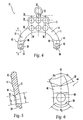
- occipital plate 10 is shown.
- occipital plate 10 is generally Y-shaped with a pair of rod supporting arms 12, 14 and a central extension 16 along with a main portion 17.
- Holes 18 extending from the front surface 11 to the back surface 13 are provided for receiving bone fasteners (not shown) for fixation of occipital plate 10 to the occiput.
- holes 18 are each provided with an expansion head bushing 20 to permit relative angulation of a locking screw or other bone fastener received therein.
- a grooved region 22 is provided along central extension 16 to facilitate bending of plate 10.
- plate 10 may be bent along grooved region 22.
- central extension 16 and grooved region 22 may be removed from plate 10.
- grooved region 22 has a thickness that may be accommodated in a rod cutter as used with the rods of the present invention.
- a clamp assembly 24, 26 is provided proximate the free end of each rod supporting arm 12,14, respectively, for clamping a portion of a rod against occipital plate 10.
- spinal rods are positionable in clamp assemblies 24, 26, by insertion from the top portion 21 of the assemblies.
- the rods may be inserted from a side portion 23 of the assemblies.
- the preferred embodiment includes two clamp assemblies, 24, 26, a number other than two may be provided.
- Rod supporting arms 12, 14 may also be bent, for example near points 12', 14'.
- occipital plate 10 includes seven fastener holes 18, with six of the holes 18 aligned in a 2 ⁇ 3 rectangular array. Three holes 18 are aligned along line 28 while three holes 18 are aligned along line 30, with lines 28, 30 being parallel to each other. In addition, while three holes 18are aligned along central line 32, two holes are aligned long each of lines 34, 26. Lines 32, 34, 36 are parallel to each other and perpendicular to lines 28, 30. In addition, grooved region 22 is aligned along a line 38 which is parallel to lines 28, 30.
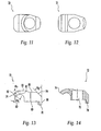
- occipital plate 10' includes four holes 18 that are disposed adjacent line 32, such that the plate may be bent along line 32 without bending along holes 18. In addition, this permits bone screws inserted in holes 18 to be angulated toward the midline 32 of the plate.
- occipital plate 10" includes a triangular array of holes 18 with one hole along line 28' and another hole along line 30'.
- occipital plate 10 includes holes 38, 40 in lower portions 42, 44 respectively. Holes 38, 40 are configured and dimensioned to receive clamping posts, as will be described.
- Rod-receiving recesses 46, 48 are generally V-shaped, with each leg of the "V” extending at an angle ⁇ 1 with respect to a line 50 extending through V-notch 52 and the center of hole 40, and further aligned parallel to lines 32, 34, 36.
- angle ⁇ 1 is between about 60° and about 80°, and more preferably about 70°.
- Arcuate stepped-in portions 54, 56 are disposed along the lowermost regions of rod supporting arms 12, 14, and preferably extend through a total angle of about 80° and about 120°, and more preferably about 100°, symmetrically with respect to line 50. As shown in FIG. 5, holes 38, 40 are preferably tapered with a first diameter D 1 on front surface 11 being smaller than a second diameter D 2 on back surface 13.
- central extension 16 is disposed along a plane 60, while rod supporting arms 12, 14 are disposed along a plane 62.
- Planes 60, 62 are not coplanar, and form an angle ⁇ 3 with respect to each other that is preferably between about 160° and about 175°, and more preferably about 170°.
- a post 64 is shown.
- One post 64 is placed in each hole 38, 40 such that the tapered head 66 rests in the hole.
- taper head 66 tapers at an angle ⁇ 4 of between about 5° and 15° and more preferably about 10° with respect to the central axis 70 of post 64, and this taper angle is also present in holes 38, 40.
- a post 64 installed in a hole 38 is shown in FIGS. 9-10.
- head 66 is provided with serrations that interlock with serrations on the inside surface of a hole 38, 40 so that a positive mechanical engagement can be achieved to assist in locking a post 64 in place with respect to the occipital plate 10.
- Post 64 also includes a body portion 68, which preferably is at least partially threaded for receiving a nut or other like-threaded fastening device.
- Clamp plate 72 for use as a part of a clamp assembly 24, 26 is shown.
- Clamp plate 72 includes a hooked serrated portion 74 for engagement with a longitudinal rod, and further includes a central pivoting hole 76 in which a post 64 is received.
- a leg 78 of each clamp plate 72 is received in an arcuate stepped-in portion 54, 56 of a rod supporting arm 12, 14.
- Front edge 80 of clamp plate 72 is disposed at an angle ⁇ 5 with respect to top edge 82, and preferably angle ⁇ 5 is about 45°.
- Back edge 84 is disposed at an angle ⁇ 6 with respect to rear edge 86, and preferably angle ⁇ 6 is about 38°.
- Outer and inner sides 88, 90, respectively, are substantially parallel with respect to each other.
- Edge 92 is disposed at an angle ⁇ 7 with respect to edge 93, with angle ⁇ 7 preferably being about 22°.
- Bushing 20 for use with the present invention is shown.
- Bushing 20 has an upper surface 116, a lower surface 118, and a sidewall 120.
- Sidewall 120 has an exterior surface 122 configured and dimensioned for polyaxial rotation within a through hole 18.
- a fastener inserted through a bore 124 which is defined by an interior surface 126 of bushing 20 and extends through both upper and lower surfaces 116, 118, can be inserted at a wide variety of orientations relative to occipital plate 10.
- bushing 20 has a frustospherical shape.
- bushing 20 can have a frustoconical shape. With either shape, bore 124 can extend through the central longitudinal axis perpendicular to the parallel upper and lower surfaces 116, 118.
- Bushing 20 includes slots 128 located on sidewall 120. Slots 128 allow sidewall 120 to expand outwardly against through hole 18. This outward expansion locks bushing 20 at the selected orientation relative to the axis of through hole 18. In order to enhance the locking effect upon expansion, exterior surface 122 of sidewall 120 and/or the periphery of through holes 18 can be provided with ridges 130. Ridges 130 provide an additional mechanism to resist motion of bushing 20 relative to occipital plate 10 once sidewall 120 has expanded outwardly. Although bushing 20 is shown having four slots, any number of slots, including one, can be used as long as the chosen number of slots provides for outward expansion of sidewall 120. Slot 128a extends from upper surface 116 through lower surface 118 while the rest of slots 128 do not extend through to lower surface 118. Slots 128 all extend from upper surface 116 of bushing 20.
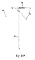
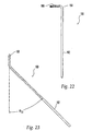
- pre-bent rods suitable for use with the present invention are shown in FIGS. 19-21.
- Each rod 140 includes a straight section 142 for running generally parallel to the spine, a bent section 144, and a serrated clamping section 146.
- Sections 142, 146 are substantially perpendicular to each other, while sections 144, 146 are disposed at an angle ⁇ 8 with respect to each other.
- angle ⁇ 8 is between about 40° and about 50 °, and more preferably approximately 45 °.
- serrated clamping section 146 includes serrations 148 about a portion of its circumference.
- serrations 148 only extend through an angle ⁇ 9 from line 152.
- angle ⁇ 9 is between about 30° and about 50°, and more preferably about 41°.
- serrations 148 are present along the circumference of section 146 of rod 148 through a total angular range ⁇ 10 as measured from center point 154.
- ⁇ 10 is between about 90° and 180°, and more preferably ⁇ 10 is about 156°.
- the pair of rods used with occipital plate 10 are typically mirror images of each other.
- a rod 140 would be used with right clamp assembly 26 while a mirror image of rod 140, as shown in FIG. 19A, would be used with left clamp assembly 24.
- pre-bent rod 160 includes a straight section 162 for running generally parallel to the spine, a transition section 164, and a serrated clamping section 166.
- Sections 162, 166 are substantially perpendicular to each other, while sections 164, 166 are disposed at an angle ⁇ 11 with respect to each other.
- angle ⁇ 11 is between about 40° and about 50°, and more preferably approximately 45°.
- Pre-bent rods 140, 160 are shown retained in clamp assemblies 24, 26, respectively, in FIG. 24. Although the pair of rods used with occipital plate 10 are typically mirror images of each other, for illustrative purposes only, one of each rod 140, 160 is shown. As seen particularly with regard to clamp assembly 24, clamp plate 72 rotates about post 64, and may be fixed in place using a nut 168. Rod receiving recesses 46, 48 are used to further lock a rod 140, 160 in place.
- occipital plate 200 includes seven holes 18 for receiving bone fasteners. However, in this embodiment, holes 18 are disposed about four parallel lines 202, 204, 206, 208 instead of three.
- pre-bent rods are clamped to occipital plate 200 using set screws 210 extending through a U-shaped or C-shaped section 216, and which are disposed about an axis 212 that may be aligned with or slightly offset from the center of a rod held in region 214.
- FIGS. 25-31 Similar to occipital plate 10, occipital plate 200 includes seven holes 18 for receiving bone fasteners. However, in this embodiment, holes 18 are disposed about four parallel lines 202, 204, 206, 208 instead of three.
- pre-bent rods are clamped to occipital plate 200 using set screws 210 extending through a U-shaped or C-shaped section 216, and which are disposed about an axis 212 that may be aligned with or slightly offset from the
- an occipital plate 250 is provided with nine holes 18 disposed about four parallel lines 254, 256, 258, 260.
- sections 262 are provided for clamping spinal fixation rods to occipital plate 250.
- a threaded set screw (not shown) is threadably received in like-threaded hole 264, which is preferably aligned along an axis 266 disposed at an angle ⁇ 12 with respect to plate wall 268.
- angle ⁇ 12 is between about 50° and about 70°, and more preferably about 60°.
- threaded hole 264 aligns a set screw to be offset from the center of a rod seated in region 270 and centered about point 272.
- FIGS. 30-31 Additional embodiments of occipital plates are shown in FIGS. 30-31.
- expansion head screws 282 are shown installed or partially installed in plate holes 18.
- Occipital plates 280, 300 include notched regions 284, 302, respectively, to facilitate bending.
- side clamping assemblies 286, 304 receive rods 290, 308 that are fixed with a set screw extending in holes 288, 306, respectively.
- side clamping assemblies 286, 304 are angulated such that rods 290, 308 are disposed at an angle of between about 20° and about 30°, and more preferably about 25 °with respect to the plane of the plate prior to bending.
- cylindrical rods with a diameter of 3.5 mm are used as the spinal rods or pre-bent rods.
- straight rods may be used and oriented accordingly by a surgeon using a rod bender.
- screw holes have been positioned along the midline of the plate for use at the midline of the occiput, since the bone thickness there is greater than on the sides.
- the screw holes may be angled about 12° to facilitate access to the screws with a screwdriver, and to enhance pull-out strength of the screws due to the wedge effect.
- expansion head screws are preferred, other non-locking screws may be used.
- Arc shaped cuts between the clamping assemblies or arrangements of each plate allow the placement of a bone graft.
- occipital plate 10 is formed of titanium.
- the shape of the occipital plate facilitates polyaxial bending thereof.
- the number of holes provided in an occipital plate of the present invention for receiving bone screws may be varied, as may the pattern of the holes and the relative alignment. Other screw hole shapes such as an oval shape, and other hole sizes may be used, as well as alternative means for locking screws. Bushings may not be included in some embodiments.
- Alternative fasteners for attaching an occipital plate to bone include staples and wires.
- the C-shaped clamping sections of some embodiments of the occipital plate may instead include full-circle regions for receiving rods.
- a sleeve for receiving the rods may extend across some or the entire the length of the occipital plate.
- two smaller occipital plates are provided for securement to the occiput, with each plate having a single clamp assembly and receiving one rod.
Claims (22)
- Okzipitalplatte (10) umfassend:dadurch gekennzeichnet, dasseine Vorderseite (11), eine Rückseite (13), einen Mittelabschnitt (16), zwei Schenkelabschnitte (12,14), eine Mehrzahl von in dem Mittelabschnitt (16) angeordneten Knochenschraubenlöchern (18) und zumindest ein an der Vorderseite (11) in der Nähe eines freien Endes von zumindest einem der Schenkelabschnitte (12,14) angeordnetes Klemmmittel (24,26), wobei die Platte (10) biegbar ist, um sich an das Okziput anzupassen,A) die Platte (10) Y-förmig ist; undB) zumindest eines der Löcher (18) mit einer Buchse (20) versehen ist, welche eine polyaxiale Ausrichtung der in das Loch einzuführenden Schraube ermöglicht.
- Okzipitalplatte (10) nach Anspruch 1, dadurch gekennzeichnet, dass sie weiterhin einen vorgebogenen Stab (140) mit zwei im wesentlichen rechtwinkelig zueinander angeordneten und zur Einführung in das Klemmmittel (24,26) bestimmten Abschnitten (142, 146) umfasst.
- Okzipitalplatte (10) nach Anspruch 1 oder 2, dadurch gekennzeichnet, dass der Mittelabschnitt (16) einen oberen Abschnitt, einen unteren Abschnitt, und einen dazwischen befindlichen gerillten Abschnitt beinhaltet, wobei der obere Abschnitt ein Knochenschraubenloch (18) aufweist.
- Okzipitalplatte (10) nach Anspruch 3, dadurch gekennzeichnet, dass der gerillte Abschnitt (22) biegsam ist, damit der obere Abschnitt in einem Winkel in Bezug auf den unteren Abschnitt angeordnet werden kann.
- Okzipitalplatte (10) nach Anspruch 3, dadurch gekennzeichnet, dass die Schenkelabschnitte (12, 14) und zumindest ein Teil des Mittelabschnitts (16) in nicht parallelen Ebenen angeordnet sind.
- Okzipitalplatte (10) nach Anspruch 5, dadurch gekennzeichnet, dass die Ebenen einander in einem Winkel von zwischen etwa 160° und etwa 175° schneiden.
- Okzipitalplatte (10) nach Anspruch 6, dadurch gekennzeichnet, dass die Ebenen einander in einem Winkel von etwa 170° schneiden.
- Okzipitalplatte (10) nach einem der Ansprüche 1 bis 7, dadurch gekennzeichnet, dass die Klemmmittel (24, 26) ein Schwenkelement und eine Klemmplatte umfassen, wobei die Klemmplatte um das Schwenkelement herum schwenkbar ist.
- Okzipitalplatte (10) nach Anspruch 8, dadurch gekennzeichnet, dass die Klemmplatte weiterhin ein Loch umfasst, wobei das Schwenkelement in dem Loch aufgenommen wird.
- Okzipitalplatte (10) nach Anspruch 9, dadurch gekennzeichnet, dass das Schwenkelement weiterhin eine Verjüngung mit Kerbverzahnungen umfasst und der Schenkelabschnitt weiterhin ein sich verjüngendes Loch mit Kerbverzahnungen umfasst, wobei die Kerbverzahnungen der Verjüngung in formschlüssiger Verbindung mit den Kerbverzahnungen des sich verjüngenden Lochs stehen.
- Okzipitalplatte (10) nach Anspruch 10, dadurch gekennzeichnet, dass der Durchmesser des sich verjüngenden Lochs von der Rückseite zu der Vorderseite hin zunimmt.
- Okzipitalplatte (10) nach Anspruch 11, dadurch gekennzeichnet, dass die Klemmplatte mit einem Befestigungsmittel an dem Schwenkelement befestigt ist.
- Okzipitalplatte (10) nach einem der Ansprüche 1 bis 12, dadurch gekennzeichnet, dass der Schenkelabschnitt zusätzlich eine erste Stabaufnahmevertiefung und die Klemmplatte zusätzlich eine zweite Stabaufnahmevertiefung umfassen, wobei die erste und die zweite Stabaufnahmevertiefung im allgemeinen einander gegenüberliegend angeordnet sind.
- Okzipitalplatte (10) nach Anspruch 13, dadurch gekennzeichnet, dass die zweite Vertiefung Kerbverzahnungen aufweist.
- Okzipitalplatte (10) nach einem der Ansprüche 1 bis 14, dadurch gekennzeichnet, dass die in dem unteren Abschnitt befindlichen Knochenschraubenlöcher (18) in einer rechteckigen Gruppierung angeordnet sind.
- Okzipitalplatte (10) nach Anspruch 15, dadurch gekennzeichnet, dass zumindest eine Gruppe von Knochenschraubenlöchern (18) in der Gruppierung entlang einer zwischen den Schenkelabschnitten (12, 14) verlaufenden Zentralachse der Platte angeordnet ist.
- Okzipitalplatte (10) nach Anspruch 16, dadurch gekennzeichnet, dass das in dem oberen Abschnitt befindliche Knochenschraubenloch (18) auf der Zentralachse angeordnet ist.
- Okzipitalplatte (10) nach einem der Ansprüche 1 bis 14, dadurch gekennzeichnet, dass zumindest zwei Knochenschraubenlöcher (18) koaxial angeordnet sind.
- Okzipitalplatte (10) nach einem der Ansprüche 1 bis 18, dadurch gekennzeichnet, dass sie entlang zumindest zweier im allgemeinen parallel verlaufender Achsen biegbar ist.
- Okzipitalplatte (10) nach einem der Ansprüche 1 bis 18, dadurch gekennzeichnet, dass sie entlang zumindest zweier im allgemeinen rechtwinkelig zueinander verlaufender Achsen biegbar ist.
- Okzipitalplatte (10) nach einem der Ansprüche 2 bis 20, dadurch gekennzeichnet, dass der vorgebogene Stab einen geraden Abschnitt, einen gebogenen Abschnitt und einen mit Kerbverzahnungen versehenen Klemmabschnitt umfasst, wobei der gerade Abschnitt und der mit Kerbverzahnungen versehene Klemmabschnitt im wesentlichen rechtwinkelig zueinander angeordnet sind, während der mit Kerbverzahnungen versehene Klemmabschnitt und der gebogene Abschnitt in einem Winkel von ungefähr 45° zueinander angeordnet sind.
- Okzipitalplatte (10) nach Anspruch 21, dadurch gekennzeichnet, dass der kerbverzahnte Klemmabschnitt im allgemeinen zylindrisch ausgebildet ist und über den Umfang hinweg in einem Winkelbereich zwischen 90° und 180° Kerbverzahnungen umfasst.
Applications Claiming Priority (3)
| Application Number | Priority Date | Filing Date | Title |
|---|---|---|---|
| US09/788,639 US6902565B2 (en) | 2001-02-21 | 2001-02-21 | Occipital plate and system for spinal stabilization |
| US788639 | 2001-02-21 | ||
| PCT/US2002/005308 WO2002067791A2 (en) | 2001-02-21 | 2002-02-19 | Occipital plate and system for spinal stabilization |
Publications (2)
| Publication Number | Publication Date |
|---|---|
| EP1372501A2 EP1372501A2 (de) | 2004-01-02 |
| EP1372501B1 true EP1372501B1 (de) | 2004-12-15 |
Family
ID=25145102
Family Applications (1)
| Application Number | Title | Priority Date | Filing Date |
|---|---|---|---|
| EP02714963A Expired - Lifetime EP1372501B1 (de) | 2001-02-21 | 2002-02-19 | Occiputplatte und system zur stabilisierung der wirbelsäule |
Country Status (16)
| Country | Link |
|---|---|
| US (2) | US6902565B2 (de) |
| EP (1) | EP1372501B1 (de) |
| JP (1) | JP4202143B2 (de) |
| AR (1) | AR033864A1 (de) |
| AT (1) | ATE284648T1 (de) |
| AU (1) | AU2002247190B2 (de) |
| BR (1) | BR0207472A (de) |
| CA (1) | CA2438861C (de) |
| DE (1) | DE60202267T2 (de) |
| DK (1) | DK1372501T3 (de) |
| ES (1) | ES2231678T3 (de) |
| HK (1) | HK1061339A1 (de) |
| MX (1) | MXPA03007509A (de) |
| NZ (1) | NZ527250A (de) |
| PT (1) | PT1372501E (de) |
| WO (1) | WO2002067791A2 (de) |
Cited By (1)
| Publication number | Priority date | Publication date | Assignee | Title |
|---|---|---|---|---|
| US8506567B2 (en) | 2009-02-04 | 2013-08-13 | Lanx, Inc. | Occipital plate fixation system |
Families Citing this family (132)
| Publication number | Priority date | Publication date | Assignee | Title |
|---|---|---|---|---|
| US6599290B2 (en) | 2001-04-17 | 2003-07-29 | Ebi, L.P. | Anterior cervical plating system and associated method |
| JP2004537354A (ja) | 2001-07-20 | 2004-12-16 | スパイナル・コンセプツ・インコーポレーテッド | 脊椎安定化システムおよび方法 |
| US6755833B1 (en) | 2001-12-14 | 2004-06-29 | Kamaljit S. Paul | Bone support assembly |
| US7070599B2 (en) | 2002-07-24 | 2006-07-04 | Paul Kamaljit S | Bone support assembly |
| US7232441B2 (en) * | 2002-02-13 | 2007-06-19 | Cross Medicalproducts, Inc. | Occipital plate and rod system |
| US20040153338A1 (en) * | 2002-05-08 | 2004-08-05 | Back Kim | Medical information system |
| US7001389B1 (en) | 2002-07-05 | 2006-02-21 | Navarro Richard R | Fixed and variable locking fixation assembly |
| US7575588B2 (en) * | 2003-02-03 | 2009-08-18 | Warsaw Orthopedic Inc. | Midline occipital vertebral fixation system |
| WO2004071276A2 (en) | 2003-02-05 | 2004-08-26 | Pioneer Laboratories, Inc. | Bone plate system |
| JP4346358B2 (ja) * | 2003-06-20 | 2009-10-21 | Necエレクトロニクス株式会社 | 化学増幅型レジスト組成物およびそれを用いた半導体装置の製造方法、パターン形成方法 |
| US8167917B2 (en) * | 2003-09-24 | 2012-05-01 | Spinefrontier Lls | Apparatus and method for spine fixation |
| US7740649B2 (en) | 2004-02-26 | 2010-06-22 | Pioneer Surgical Technology, Inc. | Bone plate system and methods |
| US8900277B2 (en) | 2004-02-26 | 2014-12-02 | Pioneer Surgical Technology, Inc. | Bone plate system |
| US7942913B2 (en) * | 2004-04-08 | 2011-05-17 | Ebi, Llc | Bone fixation device |
| US7942912B2 (en) * | 2004-05-25 | 2011-05-17 | University Of Utah Research Foundation | Occipitocervical plate |
| US8241337B2 (en) * | 2004-05-25 | 2012-08-14 | Brockmeyer Douglas L | Occipitocervical plate |
| KR100858306B1 (ko) * | 2004-06-14 | 2008-09-11 | 엠.에스. 아브두 | 정형외과 장치 |
| US20060082015A1 (en) * | 2004-09-30 | 2006-04-20 | Inion Ltd. | Surgical implant shaping instrument, surgical system and method |
| WO2006058221A2 (en) | 2004-11-24 | 2006-06-01 | Abdou Samy M | Devices and methods for inter-vertebral orthopedic device placement |
| US7527640B2 (en) | 2004-12-22 | 2009-05-05 | Ebi, Llc | Bone fixation system |
| US7621942B2 (en) | 2005-03-21 | 2009-11-24 | Zimmer Spine, Inc. | Variable geometry occipital fixation plate |
| US20060229611A1 (en) * | 2005-03-30 | 2006-10-12 | Sdgi Holdings, Inc. | Spinal rod connector |
| US7931681B2 (en) * | 2005-04-14 | 2011-04-26 | Warsaw Orthopedic, Inc. | Anti-backout mechanism for an implant fastener |
| EP1876975A2 (de) | 2005-04-27 | 2008-01-16 | James Marino | Verfahren, system und satz mit einer monoplanaren pedikelschraube |
| US7824433B2 (en) | 2005-05-03 | 2010-11-02 | Williams Lytton A | Bone anchored surgical mesh |
| US8177818B2 (en) | 2005-09-08 | 2012-05-15 | Securos, Inc. | Fixation plate |
| US7955364B2 (en) * | 2005-09-21 | 2011-06-07 | Ebi, Llc | Variable angle bone fixation assembly |
| ES2436101T3 (es) * | 2005-10-07 | 2013-12-27 | Alphatec Spine, Inc. | Placa occipital ajustable |
| CA2626145A1 (en) * | 2005-10-25 | 2007-05-03 | Anthem Orthopaedics Llc | Bone fastening assembly and bushing and screw for use therewith |
| US8100952B2 (en) * | 2005-12-22 | 2012-01-24 | Anthem Orthopaedics Llc | Drug delivering bone plate and method and targeting device for use therewith |
| US7695500B2 (en) * | 2006-03-10 | 2010-04-13 | Custom Spine, Inc. | Polyaxial occipital plate |
| US20070299441A1 (en) * | 2006-06-09 | 2007-12-27 | Zachary M. Hoffman | Adjustable Occipital Plate |
| US7776070B2 (en) * | 2006-08-02 | 2010-08-17 | Warsaw Orthopedic, Inc. | Occipital plating systems and methods |
| US7901433B2 (en) * | 2006-10-04 | 2011-03-08 | Zimmer Spine, Inc. | Occipito-cervical stabilization system and method |
| US20080091186A1 (en) * | 2006-10-13 | 2008-04-17 | Tyco Electronics Corporation | Electro-surgical device RF energy needle electrical shorting plate |
| US8147527B2 (en) | 2006-11-28 | 2012-04-03 | Zimmer Spine, Inc. | Adjustable occipital plate |
| US20080147123A1 (en) * | 2006-12-14 | 2008-06-19 | Seaspine, Inc. | Occipital plate assembly |
| US8246662B2 (en) * | 2006-12-27 | 2012-08-21 | Zimmer Spine, Inc. | Modular occipital plate |
| US8636737B2 (en) | 2006-12-27 | 2014-01-28 | Zimmer Spine, Inc. | Modular occipital plate |
| US7931676B2 (en) * | 2007-01-18 | 2011-04-26 | Warsaw Orthopedic, Inc. | Vertebral stabilizer |
| US20090036894A1 (en) * | 2007-01-29 | 2009-02-05 | Polaris Biotechnology, Inc. | Method of treating a neurological condition through correction and stabilization of the clivo-axial angle |
| US8556939B2 (en) * | 2008-01-08 | 2013-10-15 | Fraser Cummins Henderson | Mathematical relationship of strain, neurological dysfunction and abnormal behavior resulting from neurological dysfunction of the brainstem |
| US9827023B2 (en) | 2007-01-29 | 2017-11-28 | Life Spine, Inc. | Craniospinal fusion method and apparatus |
| US8182511B2 (en) * | 2007-01-29 | 2012-05-22 | Polaris Biotechnology, Inc. | Craniospinal fusion method and apparatus |
| US8403965B2 (en) * | 2007-01-29 | 2013-03-26 | Polaris Biotechnology, Inc. | Vertebra attachment method and system |
| US8083743B2 (en) * | 2007-01-29 | 2011-12-27 | Polaris Biotechnology, Inc. | Craniospinal fusion method and apparatus |
| US20080234742A1 (en) * | 2007-03-08 | 2008-09-25 | Cascarino Jose Ludovico | Head Fixation Device |
| US9072548B2 (en) * | 2007-06-07 | 2015-07-07 | Anthem Orthopaedics Llc | Spine repair assembly |
| WO2009006604A1 (en) | 2007-07-03 | 2009-01-08 | Pioneer Surgical Technology, Inc. | Bone plate system |
| US8361126B2 (en) | 2007-07-03 | 2013-01-29 | Pioneer Surgical Technology, Inc. | Bone plate system |
| EP2211742A4 (de) * | 2007-10-24 | 2012-12-19 | Nuvasive Inc | Chirurgisches fixiersystem und relevante verfahren |
| US20090125067A1 (en) * | 2007-11-08 | 2009-05-14 | Depuy Spine, Inc. | In-line occipital plate and method of use |
| WO2009073614A2 (en) * | 2007-11-29 | 2009-06-11 | University Of South Florida | Apparatus for occipito-cervical fixation enabling supplemental occipital bone fixation |
| US8317842B2 (en) * | 2007-11-30 | 2012-11-27 | Biomet C.V. | Distal tibia plating system |
| WO2009089395A2 (en) * | 2008-01-08 | 2009-07-16 | Polaris Biotechnology, Inc. | Osteointegration apparatus |
| US8088163B1 (en) | 2008-02-06 | 2012-01-03 | Kleiner Jeffrey B | Tools and methods for spinal fusion |
| US9060813B1 (en) | 2008-02-29 | 2015-06-23 | Nuvasive, Inc. | Surgical fixation system and related methods |
| US8551144B2 (en) | 2008-04-22 | 2013-10-08 | Collab Comlo, LLC | Bone plate system configurable as static or dynamic implant |
| WO2009158707A1 (en) * | 2008-06-27 | 2009-12-30 | K2M, Inc. | System and method for performing spinal surgery |
| US20100057141A1 (en) * | 2008-08-27 | 2010-03-04 | Custom Spine, Inc. | Multi-anchor anti-back out mechanism and method |
| USD853560S1 (en) | 2008-10-09 | 2019-07-09 | Nuvasive, Inc. | Spinal implant insertion device |
| US8226695B2 (en) | 2008-10-10 | 2012-07-24 | K2M, Inc. | Occipital plate for cervical fixation |
| US8187277B2 (en) * | 2008-11-17 | 2012-05-29 | Warsaw Orthopedic, Inc. | Translational occipital vertebral fixation system |
| US8864654B2 (en) | 2010-04-20 | 2014-10-21 | Jeffrey B. Kleiner | Method and apparatus for performing retro peritoneal dissection |
| US9717403B2 (en) | 2008-12-05 | 2017-08-01 | Jeffrey B. Kleiner | Method and apparatus for performing retro peritoneal dissection |
| US8366748B2 (en) | 2008-12-05 | 2013-02-05 | Kleiner Jeffrey | Apparatus and method of spinal implant and fusion |
| IT1392298B1 (it) | 2008-12-17 | 2012-02-24 | N B R New Biotechnology Res | Stabilizzatore vertebrale modulare. |
| US9247943B1 (en) | 2009-02-06 | 2016-02-02 | Kleiner Intellectual Property, Llc | Devices and methods for preparing an intervertebral workspace |
| USD656610S1 (en) | 2009-02-06 | 2012-03-27 | Kleiner Jeffrey B | Spinal distraction instrument |
| US20100222825A1 (en) * | 2009-03-02 | 2010-09-02 | Warsaw Orthopedic, Inc. | Side-loading occipital vertebral fixation system |
| US20100256687A1 (en) | 2009-04-01 | 2010-10-07 | Merete Medical Gmbh | Fixation Device and Method of Use for a Ludloff Osteotomy Procedure |
| DE102009016394B4 (de) | 2009-04-07 | 2016-02-11 | Merete Medical Gmbh | Vorrichtung zur winkelstabilen Fixation und Kompression einer Bruchstelle bzw. Osteotomie an einem Knochen |
| US8348981B2 (en) * | 2009-06-23 | 2013-01-08 | Aesculap Implany Systems, LLC | Minimal access occipital plate |
| US9011500B2 (en) * | 2009-07-29 | 2015-04-21 | Globus Medical, Inc. | Clivus plate |
| US8685031B2 (en) | 2009-09-18 | 2014-04-01 | Spinal Surgical Strategies, Llc | Bone graft delivery system |
| USD723682S1 (en) | 2013-05-03 | 2015-03-03 | Spinal Surgical Strategies, Llc | Bone graft delivery tool |
| US9060877B2 (en) | 2009-09-18 | 2015-06-23 | Spinal Surgical Strategies, Llc | Fusion cage with combined biological delivery system |
| US9173694B2 (en) | 2009-09-18 | 2015-11-03 | Spinal Surgical Strategies, Llc | Fusion cage with combined biological delivery system |
| US20170238984A1 (en) | 2009-09-18 | 2017-08-24 | Spinal Surgical Strategies, Llc | Bone graft delivery device with positioning handle |
| US10245159B1 (en) | 2009-09-18 | 2019-04-02 | Spinal Surgical Strategies, Llc | Bone graft delivery system and method for using same |
| USD750249S1 (en) | 2014-10-20 | 2016-02-23 | Spinal Surgical Strategies, Llc | Expandable fusion cage |
| US8906028B2 (en) | 2009-09-18 | 2014-12-09 | Spinal Surgical Strategies, Llc | Bone graft delivery device and method of using the same |
| US9629729B2 (en) | 2009-09-18 | 2017-04-25 | Spinal Surgical Strategies, Llc | Biological delivery system with adaptable fusion cage interface |
| US9186193B2 (en) | 2009-09-18 | 2015-11-17 | Spinal Surgical Strategies, Llc | Fusion cage with combined biological delivery system |
| US10973656B2 (en) | 2009-09-18 | 2021-04-13 | Spinal Surgical Strategies, Inc. | Bone graft delivery system and method for using same |
| US20110106085A1 (en) * | 2009-10-30 | 2011-05-05 | Warsaw Orthopedic, Inc. | Adjustable occipital vertebral fixation system |
| WO2011053962A1 (en) * | 2009-11-02 | 2011-05-05 | Life Spine, Inc. | Laminoplasty rod system |
| US8764806B2 (en) | 2009-12-07 | 2014-07-01 | Samy Abdou | Devices and methods for minimally invasive spinal stabilization and instrumentation |
| TWI397394B (zh) * | 2009-12-21 | 2013-06-01 | Ind Tech Res Inst | 撓性脊椎固定結構 |
| WO2011076205A1 (de) | 2009-12-22 | 2011-06-30 | Merete Medical Gmbh | Knochenplattensystem für die osteosynthese |
| TWI388308B (zh) * | 2009-12-31 | 2013-03-11 | Ind Tech Res Inst | 撓性脊椎固定結構 |
| US8702758B2 (en) | 2009-12-31 | 2014-04-22 | Industrial Technology Research Institute | Flexible spine fixing structure |
| US8986351B2 (en) * | 2010-01-26 | 2015-03-24 | Pioneer Surgical Technology, Inc. | Occipital plate for spinal fusion |
| US9381044B2 (en) | 2010-01-26 | 2016-07-05 | Pioneer Surgical Technology, Inc. | Posterior spinal stabilization plate device |
| US8647369B2 (en) | 2010-05-19 | 2014-02-11 | Josef E. Gorek | Minimal profile anterior bracket for spinal fixation |
| JP6193121B2 (ja) * | 2010-07-21 | 2017-09-06 | シンセス ゲゼルシャフト ミット ベシュレンクテル ハフツングSynthes Gmbh | 骨接合装置 |
| US8518042B2 (en) * | 2010-10-19 | 2013-08-27 | Biomet Manufacturing, Llc | Orthopedic plate assembly for a distal radius having re-contouring features and method for using same |
| US9387013B1 (en) | 2011-03-01 | 2016-07-12 | Nuvasive, Inc. | Posterior cervical fixation system |
| US8992579B1 (en) | 2011-03-08 | 2015-03-31 | Nuvasive, Inc. | Lateral fixation constructs and related methods |
| US9480510B2 (en) | 2011-03-23 | 2016-11-01 | Spinecraft, LLC | Devices, systems and methods of attaching same to the spine |
| DE202011051165U1 (de) | 2011-08-31 | 2011-11-14 | Merete Medical Gmbh | Anatomisch angepasste, plantare Knochenplatte sowie Knochenplattensystem |
| US8845728B1 (en) | 2011-09-23 | 2014-09-30 | Samy Abdou | Spinal fixation devices and methods of use |
| US9216042B2 (en) * | 2011-12-09 | 2015-12-22 | Pioneer Surgical Technology, Inc. | Adjustable fixation device |
| US20130226240A1 (en) | 2012-02-22 | 2013-08-29 | Samy Abdou | Spinous process fixation devices and methods of use |
| US9060815B1 (en) | 2012-03-08 | 2015-06-23 | Nuvasive, Inc. | Systems and methods for performing spine surgery |
| US9566094B2 (en) * | 2012-03-12 | 2017-02-14 | Globus Medical, Inc. | Occipital plate systems |
| US20130253516A1 (en) * | 2012-03-23 | 2013-09-26 | John L Mackall | Occipital plate |
| DE102012103894B4 (de) | 2012-05-03 | 2016-10-27 | Merete Medical Gmbh | Knochenplattensystem für Osteosynthese |
| US9510866B2 (en) * | 2012-08-15 | 2016-12-06 | Blackstone Medical, Inc. | Pivoting spinal fixation devices |
| US9198767B2 (en) | 2012-08-28 | 2015-12-01 | Samy Abdou | Devices and methods for spinal stabilization and instrumentation |
| US9320617B2 (en) | 2012-10-22 | 2016-04-26 | Cogent Spine, LLC | Devices and methods for spinal stabilization and instrumentation |
| EP3384864A1 (de) | 2013-01-29 | 2018-10-10 | III Chester Evan Sutterlin | Okzipitalplatten-anordnungen mit polyaxialen kopfverbindern |
| US9545276B2 (en) | 2013-03-15 | 2017-01-17 | Aristotech Industries Gmbh | Fixation device and method of use for a lapidus-type plantar hallux valgus procedure |
| JP2014200430A (ja) * | 2013-04-04 | 2014-10-27 | 康寛 斉宮 | 歯列矯正用のインプラント治具 |
| US9517089B1 (en) | 2013-10-08 | 2016-12-13 | Nuvasive, Inc. | Bone anchor with offset rod connector |
| US11197703B2 (en) * | 2013-12-20 | 2021-12-14 | Kelyniam Global, Inc. | Fixation article for an implant |
| USD745162S1 (en) | 2014-01-27 | 2015-12-08 | Merete Medical Gmbh | Bone plate |
| US10857003B1 (en) | 2015-10-14 | 2020-12-08 | Samy Abdou | Devices and methods for vertebral stabilization |
| USD797290S1 (en) | 2015-10-19 | 2017-09-12 | Spinal Surgical Strategies, Llc | Bone graft delivery tool |
| ITUB20155792A1 (it) * | 2015-11-20 | 2017-05-20 | Medacta Int Sa | Placca occipitale per fissaggio occipito-cervicale e sistema per il fissaggio occipito-cervicale |
| US20170290608A1 (en) * | 2016-01-22 | 2017-10-12 | Spinal Usa, Inc. | Spinal fixation systems and methods |
| RU2615900C1 (ru) * | 2016-04-26 | 2017-04-11 | Алексей Николаевич Шкарубо | Устройство для передней стабилизации с1-с2 позвонков |
| US10744000B1 (en) | 2016-10-25 | 2020-08-18 | Samy Abdou | Devices and methods for vertebral bone realignment |
| US10973648B1 (en) | 2016-10-25 | 2021-04-13 | Samy Abdou | Devices and methods for vertebral bone realignment |
| CN107822747B (zh) * | 2017-09-22 | 2023-07-25 | 牛国旗 | 一种3d打印枕颈融合固定装置 |
| EP4108194A1 (de) | 2018-03-02 | 2022-12-28 | Stryker European Holdings I, LLC | Knochenplatten und zugehörige schrauben |
| US11179248B2 (en) | 2018-10-02 | 2021-11-23 | Samy Abdou | Devices and methods for spinal implantation |
| US11298244B2 (en) | 2019-01-31 | 2022-04-12 | K2M, Inc. | Interbody implants and instrumentation |
| US11534307B2 (en) | 2019-09-16 | 2022-12-27 | K2M, Inc. | 3D printed cervical standalone implant |
| US11877779B2 (en) | 2020-03-26 | 2024-01-23 | Xtant Medical Holdings, Inc. | Bone plate system |
| US11364055B2 (en) | 2020-09-02 | 2022-06-21 | Zavation, Llc | Occipital plate and hinged rod assembly |
| US11950811B2 (en) | 2020-09-22 | 2024-04-09 | Alphatec Spine, Inc. | Occipital plates and related methods |
Family Cites Families (74)
| Publication number | Priority date | Publication date | Assignee | Title |
|---|---|---|---|---|
| US3242922A (en) | 1963-06-25 | 1966-03-29 | Charles B Thomas | Internal spinal fixation means |
| US4289123A (en) | 1980-03-31 | 1981-09-15 | Dunn Harold K | Orthopedic appliance |
| DE3121272A1 (de) * | 1981-05-29 | 1982-12-23 | Ulrich, Max Bernhard, 7900 Ulm | Korrekturimplantat zur lumbosakralen spondylodese |
| CA1178150A (en) | 1981-06-18 | 1984-11-20 | Emmanuel Anapliotis | Nail for fixing a fracture of the femur |
| US4454876A (en) | 1982-05-25 | 1984-06-19 | University Of Pittsburgh | Pelvic fixation plate and method of implanting same |
| US4604995A (en) | 1984-03-30 | 1986-08-12 | Stephens David C | Spinal stabilizer |
| US4773402A (en) * | 1985-09-13 | 1988-09-27 | Isola Implants, Inc. | Dorsal transacral surgical implant |
| US5007909A (en) | 1986-11-05 | 1991-04-16 | Chaim Rogozinski | Apparatus for internally fixing the spine |
| GB8626409D0 (en) | 1986-11-05 | 1986-12-03 | Showell A W Sugicraft Ltd | Spinal etc fixation devices |
| DE8706912U1 (de) | 1987-05-14 | 1987-08-27 | Howmedica Gmbh, 2314 Schoenkirchen, De | |
| US4887595A (en) | 1987-07-29 | 1989-12-19 | Acromed Corporation | Surgically implantable device for spinal columns |
| GB8721661D0 (en) | 1987-09-15 | 1987-10-21 | Showell A W Sugicraft Ltd | Spinal/skull fixation device |
| GB8825909D0 (en) | 1988-11-04 | 1988-12-07 | Showell A W Sugicraft Ltd | Pedicle engaging means |
| FR2658413B1 (fr) | 1990-02-19 | 1997-01-03 | Sofamor | Dispositif d'osteosynthese pour la correction des deviations rachidiennes. |
| US5030220A (en) | 1990-03-29 | 1991-07-09 | Advanced Spine Fixation Systems Incorporated | Spine fixation system |
| WO1991016020A1 (en) | 1990-04-26 | 1991-10-31 | Danninger Medical Technology, Inc. | Transpedicular screw system and method of use |
| US5092893A (en) | 1990-09-04 | 1992-03-03 | Smith Thomas E | Human orthopedic vertebra implant |
| US5300073A (en) | 1990-10-05 | 1994-04-05 | Salut, Ltd. | Sacral implant system |
| US5127912A (en) | 1990-10-05 | 1992-07-07 | R. Charles Ray | Sacral implant system |
| US5113685A (en) | 1991-01-28 | 1992-05-19 | Acromed Corporation | Apparatus for contouring spine plates and/or rods |
| US5603713A (en) | 1991-09-24 | 1997-02-18 | Aust; Gilbert M. | Anterior lumbar/cervical bicortical compression plate |
| GB9122753D0 (en) | 1991-10-26 | 1991-12-11 | Reis Nicolas D | Internal ilio-lumbar fixator |
| JP2664614B2 (ja) | 1992-02-20 | 1997-10-15 | ジ・ベ・エス ソシエテ アノニム | 頸椎の矯正、固定、締付け及び牽引用デバイス |
| FR2689750B1 (fr) * | 1992-04-10 | 1997-01-31 | Eurosurgical | Element d'ancrage osseux et dispositif d'osteosynthese rachidienne incorporant de tels elements. |
| US5545165A (en) | 1992-10-09 | 1996-08-13 | Biedermann Motech Gmbh | Anchoring member |
| US5702395A (en) | 1992-11-10 | 1997-12-30 | Sofamor S.N.C. | Spine osteosynthesis instrumentation for an anterior approach |
| ATE206602T1 (de) | 1992-11-12 | 2001-10-15 | Neville Alleyne | Einrichtung zum schutz des herzens |
| US5545164A (en) | 1992-12-28 | 1996-08-13 | Advanced Spine Fixation Systems, Incorporated | Occipital clamp assembly for cervical spine rod fixation |
| CA2103200A1 (en) * | 1992-12-28 | 1994-06-29 | Robert S. Howland | Cervical spine rod fixation system |
| US5306275A (en) | 1992-12-31 | 1994-04-26 | Bryan Donald W | Lumbar spine fixation apparatus and method |
| US5947965A (en) | 1992-12-31 | 1999-09-07 | Bryan; Donald W. | Spinal fixation apparatus and method |
| US5330473A (en) * | 1993-03-04 | 1994-07-19 | Advanced Spine Fixation Systems, Inc. | Branch connector for spinal fixation systems |
| US5415661A (en) | 1993-03-24 | 1995-05-16 | University Of Miami | Implantable spinal assist device |
| DE69408792T2 (de) | 1993-06-11 | 1998-09-24 | Johnson & Johnson Professional | Chirurgisches implantat |
| US5558674A (en) | 1993-12-17 | 1996-09-24 | Smith & Nephew Richards, Inc. | Devices and methods for posterior spinal fixation |
| US5476463A (en) | 1994-01-12 | 1995-12-19 | Acromed Corporation | Spinal column retaining apparatus |
| US5507745A (en) | 1994-02-18 | 1996-04-16 | Sofamor, S.N.C. | Occipito-cervical osteosynthesis instrumentation |
| US5601552A (en) * | 1994-03-18 | 1997-02-11 | Sofamor, S.N.C. | Fixing device for a rigid transverse connection device between rods of a spinal osteosynthesis system |
| US5542946A (en) | 1994-05-27 | 1996-08-06 | Sofamor S.N.C. | Hook for an occipito-cervical rod or plate of an occipito-cervical osteosynthesis instrumentation |
| US5527312A (en) | 1994-08-19 | 1996-06-18 | Salut, Ltd. | Facet screw anchor |
| DE4434574A1 (de) | 1994-09-28 | 1996-04-04 | Ulrich Heinrich | Implantat zur Korrektur und Fixierung einer Wirbelsäulenverformung |
| FR2729556B1 (fr) | 1995-01-23 | 1998-10-16 | Sofamor | Dispositif d'osteosynthese rachidienne a crochet median et appuis d'ancrage vertebral |
| US5620443A (en) | 1995-01-25 | 1997-04-15 | Danek Medical, Inc. | Anterior screw-rod connector |
| US5709686A (en) | 1995-03-27 | 1998-01-20 | Synthes (U.S.A.) | Bone plate |
| FR2732888B1 (fr) | 1995-04-11 | 1997-09-05 | Biomat | Dispositif d'osteosynthese pour consolidation du rachis cervical |
| US5582612A (en) | 1995-05-01 | 1996-12-10 | Lin; Chih-I | Vertebral fixing and retrieving device having centrally two fixation |
| US5630816A (en) | 1995-05-01 | 1997-05-20 | Kambin; Parviz | Double barrel spinal fixation system and method |
| JP2000501624A (ja) | 1995-06-06 | 2000-02-15 | エスディージーアイ・ホールディングス・インコーポレーテッド | 脊柱インストルメンテーションにおける隣接するロッドをリンク結合するための装置 |
| US5947966A (en) | 1995-06-06 | 1999-09-07 | Sdgi Holdings, Inc. | Device for linking adjacent rods in spinal instrumentation |
| US5693053A (en) | 1995-10-19 | 1997-12-02 | Sdgi Holdings, Inc. | Variable angle and transitional linking member |
| ES2155141T3 (es) | 1995-11-30 | 2001-05-01 | Synthes Ag | Dispositivo de osteosintesis. |
| EP0873090A1 (de) | 1995-12-22 | 1998-10-28 | Ohio Medical Instrument Company, Inc. | Fixierungsgerät für die wirbelsäule mit lateralen befestigbaren verbindungselementen |
| US5885284A (en) | 1996-07-11 | 1999-03-23 | Third Millennium Engineering, L.L.C. | Hinged variable length cross-link device |
| US5810815A (en) | 1996-09-20 | 1998-09-22 | Morales; Jose A. | Surgical apparatus for use in the treatment of spinal deformities |
| US6171311B1 (en) | 1996-10-18 | 2001-01-09 | Marc Richelsoph | Transverse connector |
| JP2002514100A (ja) * | 1996-10-24 | 2002-05-14 | スピナル コンセプツ,インク. | 脊椎を固定するための方法および装置 |
| AU5489898A (en) | 1997-03-17 | 1998-10-12 | Intellect Medical Limited | Cervical fixation system |
| DE29712285U1 (de) | 1997-07-11 | 1997-09-25 | Endotec Vertriebs Und Beratung | Fixationsplatte |
| US5891145A (en) * | 1997-07-14 | 1999-04-06 | Sdgi Holdings, Inc. | Multi-axial screw |
| US5954722A (en) * | 1997-07-29 | 1999-09-21 | Depuy Acromed, Inc. | Polyaxial locking plate |
| US6030389A (en) | 1997-08-04 | 2000-02-29 | Spinal Concepts, Inc. | System and method for stabilizing the human spine with a bone plate |
| US5976135A (en) | 1997-12-18 | 1999-11-02 | Sdgi Holdings, Inc. | Lateral connector assembly |
| US5980523A (en) | 1998-01-08 | 1999-11-09 | Jackson; Roger | Transverse connectors for spinal rods |
| US6179838B1 (en) | 1998-02-24 | 2001-01-30 | Daniel Fiz | Bone fixation arrangements and method |
| TW415228U (en) | 1998-04-29 | 2000-12-11 | Nat Science Council | Internal fixer for front position of the spine |
| US5989251A (en) | 1998-06-17 | 1999-11-23 | Surgical Dynamics, Inc. | Apparatus for spinal stabilization |
| EP1109502B1 (de) | 1998-09-11 | 2006-03-15 | Synthes AG Chur | Winkelverstellbares fixierungssystem für die wirbelsäule |
| US6110173A (en) | 1998-09-15 | 2000-08-29 | Advanced Spine Fixation Systems, Inc. | Transverse connector for spinal fixation systems |
| US6146382A (en) * | 1998-09-23 | 2000-11-14 | Spinal Concepts, Inc. | Occipito-cervical stabilization system and method |
| US6331179B1 (en) * | 2000-01-06 | 2001-12-18 | Spinal Concepts, Inc. | System and method for stabilizing the human spine with a bone plate |
| US6235033B1 (en) * | 2000-04-19 | 2001-05-22 | Synthes (Usa) | Bone fixation assembly |
| US6524315B1 (en) * | 2000-08-08 | 2003-02-25 | Depuy Acromed, Inc. | Orthopaedic rod/plate locking mechanism |
| US6485491B1 (en) * | 2000-09-15 | 2002-11-26 | Sdgi Holdings, Inc. | Posterior fixation system |
| US6478798B1 (en) * | 2001-05-17 | 2002-11-12 | Robert S. Howland | Spinal fixation apparatus and methods for use |
-
2001
- 2001-02-21 US US09/788,639 patent/US6902565B2/en not_active Expired - Lifetime
-
2002
- 2002-02-19 JP JP2002567166A patent/JP4202143B2/ja not_active Expired - Lifetime
- 2002-02-19 BR BR0207472-9A patent/BR0207472A/pt not_active Application Discontinuation
- 2002-02-19 DK DK02714963T patent/DK1372501T3/da active
- 2002-02-19 AT AT02714963T patent/ATE284648T1/de not_active IP Right Cessation
- 2002-02-19 AU AU2002247190A patent/AU2002247190B2/en not_active Ceased
- 2002-02-19 WO PCT/US2002/005308 patent/WO2002067791A2/en active IP Right Grant
- 2002-02-19 EP EP02714963A patent/EP1372501B1/de not_active Expired - Lifetime
- 2002-02-19 CA CA002438861A patent/CA2438861C/en not_active Expired - Fee Related
- 2002-02-19 DE DE60202267T patent/DE60202267T2/de not_active Expired - Lifetime
- 2002-02-19 NZ NZ527250A patent/NZ527250A/en unknown
- 2002-02-19 PT PT02714963T patent/PT1372501E/pt unknown
- 2002-02-19 MX MXPA03007509A patent/MXPA03007509A/es unknown
- 2002-02-19 ES ES02714963T patent/ES2231678T3/es not_active Expired - Lifetime
- 2002-02-20 AR ARP020100577A patent/AR033864A1/es unknown
-
2004
- 2004-03-10 HK HK04101749A patent/HK1061339A1/xx not_active IP Right Cessation
-
2005
- 2005-01-19 US US11/039,676 patent/US20050124994A1/en not_active Abandoned
Cited By (1)
| Publication number | Priority date | Publication date | Assignee | Title |
|---|---|---|---|---|
| US8506567B2 (en) | 2009-02-04 | 2013-08-13 | Lanx, Inc. | Occipital plate fixation system |
Also Published As
| Publication number | Publication date |
|---|---|
| DK1372501T3 (da) | 2005-01-24 |
| US20020120268A1 (en) | 2002-08-29 |
| BR0207472A (pt) | 2004-04-06 |
| AU2002247190B2 (en) | 2005-03-10 |
| DE60202267T2 (de) | 2005-12-08 |
| EP1372501A2 (de) | 2004-01-02 |
| ATE284648T1 (de) | 2005-01-15 |
| NZ527250A (en) | 2005-03-24 |
| WO2002067791A8 (en) | 2003-12-24 |
| WO2002067791A2 (en) | 2002-09-06 |
| US6902565B2 (en) | 2005-06-07 |
| MXPA03007509A (es) | 2004-07-30 |
| CA2438861C (en) | 2009-01-06 |
| HK1061339A1 (en) | 2004-09-17 |
| JP4202143B2 (ja) | 2008-12-24 |
| AR033864A1 (es) | 2004-01-07 |
| CA2438861A1 (en) | 2002-09-06 |
| WO2002067791A3 (en) | 2003-03-06 |
| JP2004523299A (ja) | 2004-08-05 |
| US20050124994A1 (en) | 2005-06-09 |
| PT1372501E (pt) | 2005-04-29 |
| ES2231678T3 (es) | 2005-05-16 |
| DE60202267D1 (de) | 2005-01-20 |
Similar Documents
| Publication | Publication Date | Title |
|---|---|---|
| EP1372501B1 (de) | Occiputplatte und system zur stabilisierung der wirbelsäule | |
| AU2002247190A1 (en) | Occipital plate and system for spinal stabilization | |
| EP1405606B1 (de) | Knochenschraube mit Gelenkkippdübel | |
| EP1152705B1 (de) | System zur fixierung der wirbelsäule | |
| US6520990B1 (en) | Lateral fixation plates for a spinal system | |
| AU747932B2 (en) | Clamping connector for spinal fixation systems | |
| US7575588B2 (en) | Midline occipital vertebral fixation system | |
| US6197028B1 (en) | Sacral implant system | |
| AU680209B2 (en) | Spinal rod transverse connector for supporting vertebral fixation elements | |
| US6623484B2 (en) | Methods and apparatus for fusionless treatment of spinal deformities | |
| US6709434B1 (en) | Spinal osteosynthesis device | |
| US5344422A (en) | Pedicular screw clamp | |
| JPH11502134A (ja) | 上部を固定する骨固定装置 | |
| JPH06277228A (ja) | 骨接合板システム | |
| JP2007516811A (ja) | 骨アンカーアセンブリ、および、骨アンカーアセンブリの製造方法 | |
| JP2000516820A (ja) | 外部骨固定システム | |
| JP2002540836A (ja) | 脊髄ロッド結合用トランスコネクタ | |
| KR101166614B1 (ko) | 정형외과용 플레이트 시스템 |
Legal Events
| Date | Code | Title | Description |
|---|---|---|---|
| PUAI | Public reference made under article 153(3) epc to a published international application that has entered the european phase |
Free format text: ORIGINAL CODE: 0009012 |
|
| 17P | Request for examination filed |
Effective date: 20030724 |
|
| AK | Designated contracting states |
Kind code of ref document: A2 Designated state(s): AT BE CH CY DE DK ES FI FR GB GR IE IT LI LU MC NL PT SE TR |
|
| 17Q | First examination report despatched |
Effective date: 20040122 |
|
| RAP1 | Party data changed (applicant data changed or rights of an application transferred) |
Owner name: SYNTHES AG CHUR |
|
| GRAP | Despatch of communication of intention to grant a patent |
Free format text: ORIGINAL CODE: EPIDOSNIGR1 |
|
| REG | Reference to a national code |
Ref country code: HK Ref legal event code: DE Ref document number: 1061339 Country of ref document: HK |
|
| GRAS | Grant fee paid |
Free format text: ORIGINAL CODE: EPIDOSNIGR3 |
|
| GRAA | (expected) grant |
Free format text: ORIGINAL CODE: 0009210 |
|
| AK | Designated contracting states |
Kind code of ref document: B1 Designated state(s): AT BE CH CY DE DK ES FI FR GB GR IE IT LI LU MC NL PT SE TR |
|
| REG | Reference to a national code |
Ref country code: GB Ref legal event code: FG4D Ref country code: CH Ref legal event code: NV Representative=s name: DR. LUSUARDI AG Ref country code: CH Ref legal event code: EP |
|
| RIN1 | Information on inventor provided before grant (corrected) |
Inventor name: EMCH, HANSJUERG, W. Inventor name: BRACE, MICHAEL Inventor name: GERBER, DAVID Inventor name: BERGER, ROGER |
|
| REG | Reference to a national code |
Ref country code: IE Ref legal event code: FG4D |
|
| REF | Corresponds to: |
Ref document number: 60202267 Country of ref document: DE Date of ref document: 20050120 Kind code of ref document: P |
|
| REG | Reference to a national code |
Ref country code: DK Ref legal event code: T3 |
|
| PG25 | Lapsed in a contracting state [announced via postgrant information from national office to epo] |
Ref country code: LU Free format text: LAPSE BECAUSE OF NON-PAYMENT OF DUE FEES Effective date: 20050219 |
|
| PG25 | Lapsed in a contracting state [announced via postgrant information from national office to epo] |
Ref country code: MC Free format text: LAPSE BECAUSE OF NON-PAYMENT OF DUE FEES Effective date: 20050228 |
|
| REG | Reference to a national code |
Ref country code: SE Ref legal event code: TRGR |
|
| REG | Reference to a national code |
Ref country code: GR Ref legal event code: EP Ref document number: 20050400625 Country of ref document: GR |
|
| REG | Reference to a national code |
Ref country code: HK Ref legal event code: GR Ref document number: 1061339 Country of ref document: HK |
|
| REG | Reference to a national code |
Ref country code: PT Ref legal event code: SC4A Free format text: AVAILABILITY OF NATIONAL TRANSLATION Effective date: 20050222 |
|
| REG | Reference to a national code |
Ref country code: ES Ref legal event code: FG2A Ref document number: 2231678 Country of ref document: ES Kind code of ref document: T3 |
|
| ET | Fr: translation filed | ||
| PLBE | No opposition filed within time limit |
Free format text: ORIGINAL CODE: 0009261 |
|
| STAA | Information on the status of an ep patent application or granted ep patent |
Free format text: STATUS: NO OPPOSITION FILED WITHIN TIME LIMIT |
|
| 26N | No opposition filed |
Effective date: 20050916 |
|
| PGFP | Annual fee paid to national office [announced via postgrant information from national office to epo] |
Ref country code: NL Payment date: 20060119 Year of fee payment: 6 |
|
| PGFP | Annual fee paid to national office [announced via postgrant information from national office to epo] |
Ref country code: PT Payment date: 20060124 Year of fee payment: 5 |
|
| PGFP | Annual fee paid to national office [announced via postgrant information from national office to epo] |
Ref country code: FI Payment date: 20060210 Year of fee payment: 5 |
|
| PGFP | Annual fee paid to national office [announced via postgrant information from national office to epo] |
Ref country code: DK Payment date: 20060215 Year of fee payment: 5 |
|
| PGFP | Annual fee paid to national office [announced via postgrant information from national office to epo] |
Ref country code: TR Payment date: 20060216 Year of fee payment: 5 |
|
| PGFP | Annual fee paid to national office [announced via postgrant information from national office to epo] |
Ref country code: GR Payment date: 20060221 Year of fee payment: 5 |
|
| PGFP | Annual fee paid to national office [announced via postgrant information from national office to epo] |
Ref country code: IE Payment date: 20060223 Year of fee payment: 5 |
|
| PGFP | Annual fee paid to national office [announced via postgrant information from national office to epo] |
Ref country code: BE Payment date: 20060310 Year of fee payment: 5 |
|
| REG | Reference to a national code |
Ref country code: CH Ref legal event code: PUE Owner name: SYNTHES GMBH Free format text: SYNTHES AG CHUR#GRABENSTRASSE 15#7002 CHUR (CH) -TRANSFER TO- SYNTHES GMBH#EIMATTSTRASSE 3#4436 OBERDORF (CH) |
|
| REG | Reference to a national code |
Ref country code: GB Ref legal event code: 732E |
|
| NLS | Nl: assignments of ep-patents |
Owner name: SYNTHES GMBH Effective date: 20061030 |
|
| REG | Reference to a national code |
Ref country code: PT Ref legal event code: PC4A Owner name: SYNTHES GMBH, CH Effective date: 20061213 |
|
| PG25 | Lapsed in a contracting state [announced via postgrant information from national office to epo] |
Ref country code: FI Free format text: LAPSE BECAUSE OF NON-PAYMENT OF DUE FEES Effective date: 20070219 |
|
| REG | Reference to a national code |
Ref country code: FR Ref legal event code: TP |
|
| PG25 | Lapsed in a contracting state [announced via postgrant information from national office to epo] |
Ref country code: PT Free format text: LAPSE BECAUSE OF NON-PAYMENT OF DUE FEES Effective date: 20070820 |
|
| REG | Reference to a national code |
Ref country code: PT Ref legal event code: MM4A Free format text: LAPSE DUE TO NON-PAYMENT OF FEES Effective date: 20070820 |
|
| REG | Reference to a national code |
Ref country code: DK Ref legal event code: EBP |
|
| PG25 | Lapsed in a contracting state [announced via postgrant information from national office to epo] |
Ref country code: CY Free format text: LAPSE BECAUSE OF NON-PAYMENT OF DUE FEES Effective date: 20070219 |
|
| REG | Reference to a national code |
Ref country code: IE Ref legal event code: MM4A |
|
| BERE | Be: lapsed |
Owner name: *SYNTHES G.M.B.H. Effective date: 20070228 |
|
| PG25 | Lapsed in a contracting state [announced via postgrant information from national office to epo] |
Ref country code: BE Free format text: LAPSE BECAUSE OF NON-PAYMENT OF DUE FEES Effective date: 20070228 |
|
| PG25 | Lapsed in a contracting state [announced via postgrant information from national office to epo] |
Ref country code: DK Free format text: LAPSE BECAUSE OF NON-PAYMENT OF DUE FEES Effective date: 20070228 Ref country code: IE Free format text: LAPSE BECAUSE OF NON-PAYMENT OF DUE FEES Effective date: 20070219 |
|
| PGFP | Annual fee paid to national office [announced via postgrant information from national office to epo] |
Ref country code: AT Payment date: 20080213 Year of fee payment: 7 |
|
| PG25 | Lapsed in a contracting state [announced via postgrant information from national office to epo] |
Ref country code: GR Free format text: LAPSE BECAUSE OF NON-PAYMENT OF DUE FEES Effective date: 20070904 |
|
| NLV4 | Nl: lapsed or anulled due to non-payment of the annual fee |
Effective date: 20080901 |
|
| PG25 | Lapsed in a contracting state [announced via postgrant information from national office to epo] |
Ref country code: NL Free format text: LAPSE BECAUSE OF NON-PAYMENT OF DUE FEES Effective date: 20080901 |
|
| PGFP | Annual fee paid to national office [announced via postgrant information from national office to epo] |
Ref country code: CY Payment date: 20060127 Year of fee payment: 5 |
|
| PG25 | Lapsed in a contracting state [announced via postgrant information from national office to epo] |
Ref country code: TR Free format text: LAPSE BECAUSE OF FAILURE TO SUBMIT A TRANSLATION OF THE DESCRIPTION OR TO PAY THE FEE WITHIN THE PRESCRIBED TIME-LIMIT Effective date: 20041215 |
|
| PG25 | Lapsed in a contracting state [announced via postgrant information from national office to epo] |
Ref country code: AT Free format text: LAPSE BECAUSE OF NON-PAYMENT OF DUE FEES Effective date: 20090219 |
|
| PGFP | Annual fee paid to national office [announced via postgrant information from national office to epo] |
Ref country code: SE Payment date: 20110211 Year of fee payment: 10 |
|
| PG25 | Lapsed in a contracting state [announced via postgrant information from national office to epo] |
Ref country code: SE Free format text: LAPSE BECAUSE OF NON-PAYMENT OF DUE FEES Effective date: 20120220 |
|
| PGFP | Annual fee paid to national office [announced via postgrant information from national office to epo] |
Ref country code: ES Payment date: 20120307 Year of fee payment: 11 |
|
| REG | Reference to a national code |
Ref country code: ES Ref legal event code: FD2A Effective date: 20140509 |
|
| PG25 | Lapsed in a contracting state [announced via postgrant information from national office to epo] |
Ref country code: ES Free format text: LAPSE BECAUSE OF NON-PAYMENT OF DUE FEES Effective date: 20130220 |
|
| REG | Reference to a national code |
Ref country code: FR Ref legal event code: PLFP Year of fee payment: 15 |
|
| REG | Reference to a national code |
Ref country code: FR Ref legal event code: PLFP Year of fee payment: 16 |
|
| REG | Reference to a national code |
Ref country code: FR Ref legal event code: PLFP Year of fee payment: 17 |
|
| PGFP | Annual fee paid to national office [announced via postgrant information from national office to epo] |
Ref country code: CH Payment date: 20180213 Year of fee payment: 17 Ref country code: DE Payment date: 20180206 Year of fee payment: 17 Ref country code: GB Payment date: 20180214 Year of fee payment: 17 |
|
| PGFP | Annual fee paid to national office [announced via postgrant information from national office to epo] |
Ref country code: IT Payment date: 20180221 Year of fee payment: 17 Ref country code: FR Payment date: 20180111 Year of fee payment: 17 |
|
| REG | Reference to a national code |
Ref country code: DE Ref legal event code: R119 Ref document number: 60202267 Country of ref document: DE |
|
| REG | Reference to a national code |
Ref country code: CH Ref legal event code: PL |
|
| GBPC | Gb: european patent ceased through non-payment of renewal fee |
Effective date: 20190219 |
|
| PG25 | Lapsed in a contracting state [announced via postgrant information from national office to epo] |
Ref country code: CH Free format text: LAPSE BECAUSE OF NON-PAYMENT OF DUE FEES Effective date: 20190228 Ref country code: LI Free format text: LAPSE BECAUSE OF NON-PAYMENT OF DUE FEES Effective date: 20190228 |
|
| PG25 | Lapsed in a contracting state [announced via postgrant information from national office to epo] |
Ref country code: GB Free format text: LAPSE BECAUSE OF NON-PAYMENT OF DUE FEES Effective date: 20190219 Ref country code: DE Free format text: LAPSE BECAUSE OF NON-PAYMENT OF DUE FEES Effective date: 20190903 |
|
| PG25 | Lapsed in a contracting state [announced via postgrant information from national office to epo] |
Ref country code: FR Free format text: LAPSE BECAUSE OF NON-PAYMENT OF DUE FEES Effective date: 20190228 Ref country code: IT Free format text: LAPSE BECAUSE OF NON-PAYMENT OF DUE FEES Effective date: 20190219 |