EP1372184A2 - Electrode system for a metal halide lamp and lamp provided with such a system - Google Patents
Electrode system for a metal halide lamp and lamp provided with such a system Download PDFInfo
- Publication number
- EP1372184A2 EP1372184A2 EP03012802A EP03012802A EP1372184A2 EP 1372184 A2 EP1372184 A2 EP 1372184A2 EP 03012802 A EP03012802 A EP 03012802A EP 03012802 A EP03012802 A EP 03012802A EP 1372184 A2 EP1372184 A2 EP 1372184A2
- Authority
- EP
- European Patent Office
- Prior art keywords
- electrode
- shaft
- bushing
- electrode system
- lamp
- Prior art date
- Legal status (The legal status is an assumption and is not a legal conclusion. Google has not performed a legal analysis and makes no representation as to the accuracy of the status listed.)
- Withdrawn
Links
- 229910001507 metal halide Inorganic materials 0.000 title claims description 9
- 150000005309 metal halides Chemical class 0.000 title claims description 9
- 229910052721 tungsten Inorganic materials 0.000 claims description 12
- 239000011195 cermet Substances 0.000 claims description 11
- 239000000463 material Substances 0.000 claims description 11
- WFKWXMTUELFFGS-UHFFFAOYSA-N tungsten Chemical compound [W] WFKWXMTUELFFGS-UHFFFAOYSA-N 0.000 claims description 11
- 239000010937 tungsten Substances 0.000 claims description 11
- 239000000919 ceramic Substances 0.000 claims description 8
- 229910018072 Al 2 O 3 Inorganic materials 0.000 claims description 3
- 230000035515 penetration Effects 0.000 claims 2
- 229910052750 molybdenum Inorganic materials 0.000 description 18
- 229910052758 niobium Inorganic materials 0.000 description 15
- 239000010955 niobium Substances 0.000 description 15
- ZOKXTWBITQBERF-UHFFFAOYSA-N Molybdenum Chemical compound [Mo] ZOKXTWBITQBERF-UHFFFAOYSA-N 0.000 description 12
- 239000011733 molybdenum Substances 0.000 description 12
- 230000008018 melting Effects 0.000 description 11
- 238000002844 melting Methods 0.000 description 11
- GUCVJGMIXFAOAE-UHFFFAOYSA-N niobium atom Chemical compound [Nb] GUCVJGMIXFAOAE-UHFFFAOYSA-N 0.000 description 10
- 238000005476 soldering Methods 0.000 description 8
- 229910000679 solder Inorganic materials 0.000 description 7
- 238000003466 welding Methods 0.000 description 4
- QSHDDOUJBYECFT-UHFFFAOYSA-N mercury Chemical compound [Hg] QSHDDOUJBYECFT-UHFFFAOYSA-N 0.000 description 3
- 229910052753 mercury Inorganic materials 0.000 description 3
- 229910052751 metal Inorganic materials 0.000 description 3
- 239000002184 metal Substances 0.000 description 3
- 239000002893 slag Substances 0.000 description 3
- XKRFYHLGVUSROY-UHFFFAOYSA-N Argon Chemical compound [Ar] XKRFYHLGVUSROY-UHFFFAOYSA-N 0.000 description 2
- 239000000654 additive Substances 0.000 description 2
- 229910045601 alloy Inorganic materials 0.000 description 2
- 239000000956 alloy Substances 0.000 description 2
- 230000008901 benefit Effects 0.000 description 2
- 239000007789 gas Substances 0.000 description 2
- 150000004820 halides Chemical class 0.000 description 2
- 229910052702 rhenium Inorganic materials 0.000 description 2
- WUAPFZMCVAUBPE-UHFFFAOYSA-N rhenium atom Chemical compound [Re] WUAPFZMCVAUBPE-UHFFFAOYSA-N 0.000 description 2
- UFHFLCQGNIYNRP-UHFFFAOYSA-N Hydrogen Chemical compound [H][H] UFHFLCQGNIYNRP-UHFFFAOYSA-N 0.000 description 1
- VYPSYNLAJGMNEJ-UHFFFAOYSA-N Silicium dioxide Chemical compound O=[Si]=O VYPSYNLAJGMNEJ-UHFFFAOYSA-N 0.000 description 1
- 238000009825 accumulation Methods 0.000 description 1
- 230000000996 additive effect Effects 0.000 description 1
- 229910052786 argon Inorganic materials 0.000 description 1
- 238000005219 brazing Methods 0.000 description 1
- 239000003795 chemical substances by application Substances 0.000 description 1
- 150000001875 compounds Chemical class 0.000 description 1
- 238000005260 corrosion Methods 0.000 description 1
- 230000007797 corrosion Effects 0.000 description 1
- 230000001419 dependent effect Effects 0.000 description 1
- 238000006073 displacement reaction Methods 0.000 description 1
- 239000011888 foil Substances 0.000 description 1
- 239000001257 hydrogen Substances 0.000 description 1
- 229910052739 hydrogen Inorganic materials 0.000 description 1
- 230000001788 irregular Effects 0.000 description 1
- 238000004519 manufacturing process Methods 0.000 description 1
- TWNQGVIAIRXVLR-UHFFFAOYSA-N oxo(oxoalumanyloxy)alumane Chemical compound O=[Al]O[Al]=O TWNQGVIAIRXVLR-UHFFFAOYSA-N 0.000 description 1
- 238000007747 plating Methods 0.000 description 1
- 238000004080 punching Methods 0.000 description 1
- 210000004243 sweat Anatomy 0.000 description 1
- 229910052715 tantalum Inorganic materials 0.000 description 1
- GUVRBAGPIYLISA-UHFFFAOYSA-N tantalum atom Chemical compound [Ta] GUVRBAGPIYLISA-UHFFFAOYSA-N 0.000 description 1
- 229910052724 xenon Inorganic materials 0.000 description 1
- FHNFHKCVQCLJFQ-UHFFFAOYSA-N xenon atom Chemical compound [Xe] FHNFHKCVQCLJFQ-UHFFFAOYSA-N 0.000 description 1
Images


Classifications
-
- H—ELECTRICITY
- H01—ELECTRIC ELEMENTS
- H01J—ELECTRIC DISCHARGE TUBES OR DISCHARGE LAMPS
- H01J61/00—Gas-discharge or vapour-discharge lamps
- H01J61/02—Details
- H01J61/36—Seals between parts of vessels; Seals for leading-in conductors; Leading-in conductors
-
- H—ELECTRICITY
- H01—ELECTRIC ELEMENTS
- H01J—ELECTRIC DISCHARGE TUBES OR DISCHARGE LAMPS
- H01J61/00—Gas-discharge or vapour-discharge lamps
- H01J61/02—Details
- H01J61/04—Electrodes; Screens; Shields
- H01J61/06—Main electrodes
- H01J61/073—Main electrodes for high-pressure discharge lamps
- H01J61/0732—Main electrodes for high-pressure discharge lamps characterised by the construction of the electrode
Definitions
- the invention is based on an electrode system for a metal halide lamp and associated lamp according to the preamble of claim 1. These are in particular lamps with an output of at least 20 W, preferably from 100 W, up to powers of 400 W, possibly over 1000 W.
- EP-A 587 238 describes a metal halide lamp with a ceramic discharge vessel known, in which a two-part implementation in an elongated Stopper capillary by means of glass solder at the end of the Plug is sealed.
- the outer part of the bushing is permeable Material (niobium stick), the inner part made of halide-resistant material (for example a pen made of tungsten or molybdenum).
- halide-resistant material for example a pen made of tungsten or molybdenum.
- another solution is used, namely the replacement of the inner Mo pin part with a cermet part.
- Whose thermal expansion coefficient can be set between that of other metal parts and that of ceramics.
- a disadvantage of such solutions is that the connection between the inner part of the bushing and the electrode is very prone to breakage. This applies both to the further processing of the electrode system and in Lifetime behavior of the system when the lamp is in operation. Ultimately, can cause the electrodes to kink to burst the discharge tubes during operation.
- WO 01/82331 tries this by a multi-part arrangement of the Bypass implementation.
- this only solves the basic problem insufficient.
- the diameter of the electrode is smaller than that of the inner part, the two components by melting the End of the inner part and embedding the electrode end therein become. Melting is often done by brazing or laser soldering.
- the inner part mostly consists of molybdenum or Mo-containing cermet. there but the melting amount on the inner part can not be within the required Accuracy can be ensured reproducibly. Remedy would offer an increase in the melting length. However, that is the limit towards the maximum permissible "welding hump height".
- the maximum allowable amount of the cant is determined by the minimum allowable Capillary inner diameter of the discharge vessel determined.
- a means for positive locking in particular a notch or groove, near the end of the electrode facing the bushing appropriate. It is so close to the end of the shaft that it is from the Material of the bushing from the connection area or melting area is encased.
- the agent comprises at least one local depression or notch.
- a circumferential depression is preferred, which is V-shaped or U-shaped, can be designed rectangular or trough-shaped.
- the notch can for example by grinding or punching.
- This notch can be an irregular or regular reduction in the Cross section of the electrode. In particular, it is a circumferential notch or U-shaped or V-shaped groove.
- the recess is a provisional fixation option for a possible coil at the distal end of an extended one Electrode shaft provides by melting the end area the execution is then finally and particularly securely fixed, similar as is known as a fixing option from US-A 5 451 837.
- the implementation can be made in one piece, or in two or more parts be constructed by the outer part of niobium or another hydrogen permeable Material, while the inner part has properties, that favors the connection with the shaft (see below).
- the inner part can be replaced by an extended shaft of the electrode so that the connection technology according to the invention on the connection between the only remaining outer bushing part and accordingly elongated core pin is applied.
- the known structure of ceramic discharge vessels also includes a Elongated capillary tube (hereinafter called capillary), where through this capillary an electrically conductive, one or two part Implementation related to the discharge from an inner part and there is an outer pin-shaped part, is passed vacuum-tight.
- the bushing is usually sealed on the outside of the stopper with glass solder.
- an electrode is attached with its shaft, which in the interior of the discharge vessel protrudes.
- the lamp power is preferably between 20 and 400 W, however Larger powers (2000 W and more) are also possible.
- the attached table shows the dimensions for different lamp powers (35, 70 and 150 W) of the following parts: lamp core pin groove execution Abschmelz Scheme power material AD [ ⁇ m] Depth T [ ⁇ m] Width B [ ⁇ m] Final distance [ ⁇ m] material AD [ ⁇ m] Length [ ⁇ m] 35 W 200 30 50 50 Mo or Nb 560 150 70 W 300 50 100 50 Mo or Nb 680 225 70 W 300 60 70 70 Mo or Nb 680 225 150 W 500 70 100 70 Cermet with Mo or Nb 800 270 150 W 500 90 80 70 Cermet with Mo or Nb 800 250
- Core pin material and outer diameter in ⁇ m; Groove in the core pin: depth T, width B and distance of the groove from the distal end of the pin, each in ⁇ m; Implementation: material and outer diameter in ⁇ m; Melting area: Length of the connection area of both components in ⁇ m.
- connection between the two components implementation and The core pin is made by laser soldering.
- the inner end region is the Implementation (hereinafter referred to as the melting range), with the electrode in contact, made of Mo, W, or a cermet, the W in one Contains amount that keeps it weldable.
- the diameter of both to be connected Parts can be approximately the same size in this embodiment.
- the Electrode is preferably made of tungsten. Your first end is in the connection area embedded, the second end faces the discharge.
- the Shaft of the electrode can still be used to limit the dead volume Helix, preferably made of molybdenum, be covered, as is known per se.
- the inner part of the current feedthrough by extending the electrode core pin (usually from Tungsten) to the outer lead-through part (usually made of niobium) replace in accordance with EP-A 1 056 115.
- the elongated shaft of the electrode can also be used with a helix to limit the dead volume, preferably made of molybdenum, as in the case of the two-part Power supply (EP-A 587 238) practiced.
- the feedthrough or at least the outer part thereof in the case of a two-part feedthrough consists of an outer part which is adapted to the (aluminum oxide) ceramic and is permeable to H 2 and O 2 (in particular a niobium pin or tube, but also the use of Tantalum is possible), which is covered with glass solder and sealed.
- the inner part of the implementation consists made of a halide resistant metal (preferably molybdenum or Tungsten or its alloys) or a corresponding cermet.
- Prefers is the material molybdenum.
- the inner part is only partly on his outer end covered with glass solder and melted.
- the inside part is in particular a pen made of cermet or molybdenum or of the higher melting Tungsten.
- the tungsten can have a rhenium additive either as an alloy or as a plating on the surface.
- the Rhenium increases the high temperature resistance and corrosion resistance of tungsten.
- molybdenum is especially for mercury-containing Suitable fillings
- W is advantageous for mercury-free fillings used. In particular, W is also for relatively small watt lamps from 70 W. suitable.
- the inner part of the two-part bushing is on one side with the outer Part (niobium stick or tube) and on the other side with the electrode connected.
- the inner part can itself be constructed in several parts, for example described in WO 01/82331.
- the stopper can be made in one part, but also in several parts. For example can in a manner known per se a stopper capillary from an annular Be part of the plug.
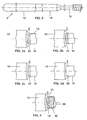
- a metal halide lamp with an output of 150 W is shown schematically in FIG. It consists of a cylindrical outer bulb 1 made of quartz glass which defines a lamp axis and is squeezed (2) and base (3) on two sides.
- the axially arranged discharge vessel 4 made of Al 2 O 3 ceramic is cylindrical or bulbous in shape and has two ends 6. It is held in the outer bulb 1 by means of two current leads 7, which are connected to the base parts 3 via foils 8.
- the power supply lines 7 are welded to bushings 9, which are each fitted in an end plug 12 at the end 6 of the discharge vessel.
- the stopper part is designed as an elongated capillary tube 12 (stopper capillary).
- the end 6 of the discharge vessel and the stopper capillary 12 are, for example, sintered together directly.
- the bushings 9 each consist of two parts.
- the outer part 13 is designed as a niobium stick and extends up to about a quarter of the length the capillary tube 12 into this.
- the inner part 14 extends inside of the capillary tube 12 towards the discharge volume. It stops on the discharge side Electrodes 15, consisting of an electrode shaft 16 Tungsten and one pushed onto the discharge end of the shaft Spiral 17.
- the inner part 14 of the implementation is on the one hand with the Electrode shaft 15 laser soldered and on the other hand with the outer part 13 the execution laser-welded.
- the niobium stick 13 is approximately 3 mm deep the stopper capillary 12 inserted and sealed by means of glass solder 10.
- the discharge vessel is filled, e.g. Argon, from mercury and additives to metal halides.
- a metal halide filling without Mercury, preferably xenon and in particular a high ignition gas Pressure well above 1.3 bar can be selected.
- FIG. 2 An electrode system is shown in detail in FIG. 2.
- implementation 9 is a system consisting of a niobium stick (or tube) as an outer part 13 and a molybdenum pin as the inner part 14.
- the niobium pin 13 is on the discharge side with the inner part 14 made of molybdenum butt welded. Inner part 14 is in the same way on the discharge side soldered to the electrode shaft 16.
- the alternative is to use an inner part 14 made of cermet with a high proportion of Mo, the remainder Al 2 O 3 .
- the shaft 16 has a diameter of 0.4 mm.
- the diameter of the inner Part is 0.8 mm, the outer part is 0.88 mm.
- the inner part 14 has that is, a 100% larger diameter than the electrode shaft 16.
- FIG. 3a The principle of the connection according to the invention is shown in FIG. 3a.
- the lamp power considered about 0.5 mm to 2 mm away from the lead-through end of the electrode shaft 16 circumferential groove 18 attached. It also has one, depending on performance Depth of 0.5 to 2 mm and a width of 0.5 to 2 mm.
- the melting area 25 extends beyond the groove 18, which is here is rectangular, from.
- the melted molybdenum serves as a solder for embedding the tungsten shaft 16.
- the groove enables an additional one Form fit and serves as a reservoir for excess melt or the slag generated when segregating cermet.
- the groove can also have a circumferential groove with a different shape
- a cross section in particular a V-shaped recess 26 (Fig. 3b) or a trough-shaped puncture 27 (Fig. 3c).
- a positive locking device that consists of two opposite one another There are notches 28 in the shaft (FIG. 3d).
- Figure 4 is on the shaft 36, which is greatly elongated and therefore replaces the inner lead-through part, a coil 20 for displacement of the dead volume is applied, which is made of molybdenum consists. The last turn 21 is held in the groove 18. While the manufacture becomes a provisional fixation up to laser welding achieved to produce the melting area.
- FIG. 5 shows an embodiment in which the bushing 30 (one-piece made of niobium) with the extended core pin 31 made of tungsten or is welded. Both components have approximately the same outside diameter.
- the means for positive locking is a notch 32.
- the connection area 33 which can contain material from both components shown here very schematically.
- FIG. 6 A further embodiment is shown in FIG. 6, in which, in addition to the first Groove 37 remote from the discharge, a second groove 38 in the vicinity of the front, discharge-side End of the shaft 39 ensures that the second Spiral end can be fixed.
- the helix is not shown. benefits result here in particular from the simplification of the automatic Orientation for the subsequent laser soldering.
- Both notches 37 and 38 are shaped like a trough with sloping side walls.
Abstract
Description
Die Erfindung geht aus von einem Elektrodensystem für eine Metallhalogenidlampe
und zugehörige Lampe gemäß dem Oberbegriff des Anspruchs 1.
Es handelt sich dabei insbesondere um Lampen mit einer Leistung von mindestens
20 W, bevorzugt ab 100 W, bis hin zu Leistungen von 400 W, ggf.
über 1000 W.The invention is based on an electrode system for a metal halide lamp
and associated lamp according to the preamble of
Aus der EP-A 587 238 ist eine Metallhalogenidlampe mit keramischem Entladungsgefäß bekannt, bei der eine zweiteilige Durchführung in einer langgestreckten Stopfenkapillare mittels Glaslot am entladungsfernen Ende des Stopfens abgedichtet ist. Der äußere Teil der Durchführung besteht aus permeablem Material (Niobstift), der innere Teil aus halogenidresistentem Material (beispielsweise Stift aus Wolfram oder Molybdän). Für höhere Lampenleistungen (bis etwa 400 W) wird eine andere Lösung angewendet, nämlich der Ersatz des inneren Mo-Stift-Teiles durch ein Cermet-Teil. Dessen thermischer Ausdehnungskoeffizient lässt sich wunschgemäß einstellen zwischen dem anderer Metallteile und dem der Keramik.EP-A 587 238 describes a metal halide lamp with a ceramic discharge vessel known, in which a two-part implementation in an elongated Stopper capillary by means of glass solder at the end of the Plug is sealed. The outer part of the bushing is permeable Material (niobium stick), the inner part made of halide-resistant material (for example a pen made of tungsten or molybdenum). For higher lamp outputs (up to about 400 W) another solution is used, namely the replacement of the inner Mo pin part with a cermet part. Whose thermal expansion coefficient can be set between that of other metal parts and that of ceramics.
Nachteilig an derartigen Lösungen ist, dass die Verbindung zwischen dem inneren Teil der Durchführung und der Elektrode sehr bruchanfällig ist. Dies gilt sowohl bei der Weiterverarbeitung des Elektrodensystems als auch im Lebensdauerverhalten des Systems im Betrieb der Lampe. Letztlich können abknickende Elektroden zum Platzen der Entladungsgefäße im Betrieb führen.A disadvantage of such solutions is that the connection between the inner part of the bushing and the electrode is very prone to breakage. This applies both to the further processing of the electrode system and in Lifetime behavior of the system when the lamp is in operation. Ultimately, can cause the electrodes to kink to burst the discharge tubes during operation.
Die WO 01/82331 versucht dies durch eine mehrteilige Anordnung der Durchführung zu umgehen. Jedoch löst dies das grundsätzliche Problem nur unzureichend. Gemeinhin ist der Durchmesser der Elektrode kleiner als der des inneren Teils, wobei die beiden Komponenten durch Abschmelzen des Endes des inneren Teils und Einbetten des Elektrodenendes darin verbunden werden. Oft geschieht das Abschmelzen durch Hart- oder Laserlöten. Das innere Teil besteht meist aus Molybdän oder Mo-haltigem Cermet. Dabei kann aber die Abschmelzmenge am inneren Teil nicht innerhalb der erforderlichen Genauigkeit reproduzierbar sichergestellt werden. Abhilfe würde eine Vergrößerung der Abschmelzlänge bieten. Dem steht jedoch die Begrenzung der maximal zulässigen "Schweißbuckelhöhe" entgegen. Damit ist eine Überhöhung gemeint, die im Bereich der Schweiß- oder Lötzone aus einer lokalen Schweißgut- oder Lotanhäufung resultiert. Es kann sich auch um Schlacke (insbesondere im Falle einer Cermet-Verbindung) handeln. Das maximal zulässige Maß der Überhöhung wird dabei durch den minimal zulässigen Kapillar-Innendurchmesser des Entladungsgefäßes bestimmt.WO 01/82331 tries this by a multi-part arrangement of the Bypass implementation. However, this only solves the basic problem insufficient. Generally the diameter of the electrode is smaller than that of the inner part, the two components by melting the End of the inner part and embedding the electrode end therein become. Melting is often done by brazing or laser soldering. The inner part mostly consists of molybdenum or Mo-containing cermet. there but the melting amount on the inner part can not be within the required Accuracy can be ensured reproducibly. Remedy would offer an increase in the melting length. However, that is the limit towards the maximum permissible "welding hump height". So that is an elevation meant in the area of the welding or soldering zone a local accumulation of weld metal or solder results. It can also be act as slag (especially in the case of a cermet compound). The The maximum allowable amount of the cant is determined by the minimum allowable Capillary inner diameter of the discharge vessel determined.
Es ist Aufgabe der vorliegenden Erfindung, ein Elektrodensystem gemäß
dem Oberbegriff des Anspruchs 1 bereitzustellen, wobei die Verbindung
zwischen Durchführung und Elektrode so konzipiert ist, dass sie dauerhaft
mechanischen und thermischen Belastungen standhält. It is an object of the present invention to provide an electrode system
to provide the preamble of
Diese Aufgabe wird durch die kennzeichnenden Merkmale des Anspruchs 1
gelöst. Besonders vorteilhafte Ausgestaltungen finden sich in den abhängigen
Ansprüchen.This object is achieved by the characterizing features of
Erfindungsgemäß ist ein Mittel zum Formschluss, insbesondere eine Kerbe oder Nut, in der Nähe des der Durchführung zugewandten Endes der Elektrode angebracht. Es ist so nahe am Ende des Schafts angebracht, dass es vom Material der Durchführung aus dem Verbindungsbereich bzw. Abschmelzbereich ummantelt wird. Das Mittel umfasst zumindest eine lokale Vertiefung oder Kerbe. Bevorzugt ist eine umlaufende Vertiefung, die V- oder U-förmig, rechtwinkelig oder trogförmig gestaltet sein kann. Die Kerbe kann beispielsweise durch Schleifen oder Stanzen hergestellt werden.According to the invention is a means for positive locking, in particular a notch or groove, near the end of the electrode facing the bushing appropriate. It is so close to the end of the shaft that it is from the Material of the bushing from the connection area or melting area is encased. The agent comprises at least one local depression or notch. A circumferential depression is preferred, which is V-shaped or U-shaped, can be designed rectangular or trough-shaped. The notch can for example by grinding or punching.
Diese Kerbe kann eine unregelmäßige oder regelmäßige Verringerung des Querschnitts der Elektrode sein. Insbesondere ist sie eine umlaufende Kerbe oder Nut in U- oder V-Form. Beim Verbinden der Durchführung mit der Elektrode, die meist durch Löten (Hart- oder Laserlöten) oder Schweißen geschieht, wird nunmehr ein zusätzlicher Formschluss erreicht, der die mechanische Belastbarkeit der Verbindung erhöht. Auch der Ausschuss in Folge unzulässig großer Schweiß/Lötzonenüberhöhung wird reduziert, da nun ein Reservoir für die überschüssige Schmelze bzw. Schlacke zur Verfügung steht.This notch can be an irregular or regular reduction in the Cross section of the electrode. In particular, it is a circumferential notch or U-shaped or V-shaped groove. When connecting the bushing to the electrode, which is usually done by soldering (hard or laser soldering) or welding, an additional positive connection is now achieved, which is the mechanical Resilience of the connection increased. The committee in a row Inadmissibly large sweat / soldering zone increase is reduced, because now a Reservoir for the excess melt or slag available stands.
Ein zusätzlicher Vorteil ist, dass die Vertiefung eine provisorische Fixiermöglichkeit für eine etwaige Wendel am entladungsfernen Ende eines verlängerten Elektrodenschafts bietet, die durch das Aufschmelzen des Endbereichs der Durchführung dann endgültig und besonders sicher fixiert wird, ähnlich wie dies als Fixiermöglichkeit aus US-A 5 451 837 bekannt ist.An additional advantage is that the recess is a provisional fixation option for a possible coil at the distal end of an extended one Electrode shaft provides by melting the end area the execution is then finally and particularly securely fixed, similar as is known as a fixing option from US-A 5 451 837.
Die Durchführung kann einteilig hergestellt sein, oder zwei- oder mehrteilig aufgebaut sein, indem der äußere Teil aus Niob oder einem anderen wasserstoffpermeablem Material besteht, während der innere Teil Eigenschaften, die die Verbindung mit dem Schaft begünstigt, besitzt (s.u.). Der innere Teil kann durch einen verlängerten Schaft der Elektrode ersetzt werden, so dass die erfindungsgemäße Verbindungstechnik auf die Verbindung zwischen dem alleine verbleibenden äußeren Durchführungsteil und dem entsprechend verlängerten Kernstift angewendet wird.The implementation can be made in one piece, or in two or more parts be constructed by the outer part of niobium or another hydrogen permeable Material, while the inner part has properties, that favors the connection with the shaft (see below). The inner part can be replaced by an extended shaft of the electrode so that the connection technology according to the invention on the connection between the only remaining outer bushing part and accordingly elongated core pin is applied.
Der bekannte Aufbau keramischer Entladungsgefäße umfasst außerdem ein langgezogenes Kapillarrohr (im folgenden Stopfenkapillare genannt), wobei durch diese Stopfenkapillare eine elektrisch leitende, ein- oder zweiteilige Durchführung, die bezogen auf die Entladung aus einem inneren Teil und einem äußeren stiftförmigen Teil besteht, vakuumdicht hindurchgeführt ist. Die Durchführung ist meist außen am Stopfen durch Glaslot abgedichtet. An der Durchführung ist innen eine Elektrode mit ihrem Schaft befestigt, die in das Innere des Entladungsgefäßes hineinragt.The known structure of ceramic discharge vessels also includes a Elongated capillary tube (hereinafter called capillary), where through this capillary an electrically conductive, one or two part Implementation related to the discharge from an inner part and there is an outer pin-shaped part, is passed vacuum-tight. The bushing is usually sealed on the outside of the stopper with glass solder. On the leadthrough an electrode is attached with its shaft, which in the interior of the discharge vessel protrudes.
Bevorzugt beträgt die Leistung der Lampe zwischen 20 und 400 W, aber auch größere Leistungen (2000 W und mehr) sind möglich.The lamp power is preferably between 20 and 400 W, however Larger powers (2000 W and more) are also possible.
Die beiliegende Tabelle zeigt die Bemaßung für verschiedene Lampenleistungen
(35, 70 und 150 W) folgender Teile:
Die Verbindung zwischen den beiden Komponenten Durchführung und Kernstift erfolgt durch Laserlöten.The connection between the two components implementation and The core pin is made by laser soldering.
Bevorzugt ist das Verhältnis der Breite B der Kerbe und ihrer Tiefe T im Bereich B/T = 1:1, insbesondere sollte es zwischen 0,8 und 2,2 liegen. Aus Stabilitätsgründen sollte der verbleibende Außendurchmesser des Kernstiftes im Bereich der Kerbe mindestens 60 % des ursprünglichen Durchmessers betragen, bevorzugt sind 65 bis 75 %.The ratio of the width B of the notch and its depth T in the region is preferred B / T = 1: 1, in particular it should be between 0.8 and 2.2. For reasons of stability should the remaining outer diameter of the core pin in the Area of the notch must be at least 60% of the original diameter, 65 to 75% are preferred.
Im Falle einer zweiteiligen Durchführung ist der innere Endbereich der Durchführung (im folgenden Abschmelzbereich genannt), der mit der Elektrode in Kontakt steht, aus Mo, W, oder einem Cermet gefertigt, das W in einer Menge enthält, die es schweißfähig hält. Der Durchmesser beider zu verbindenden Teile kann in dieser Ausführungsform etwa gleich groß sein. Die Elektrode besteht bevorzugt aus Wolfram. Ihr erstes Ende ist im Verbindungsbereich eingebettet, das zweite Ende ist der Entladung zugewandt. Der Schaft der Elektrode kann zum Begrenzen des Totvolumens noch mit einer Wendel, bevorzugt aus Molybdän, ummantelt sein, wie an sich bekannt.In the case of a two-part implementation, the inner end region is the Implementation (hereinafter referred to as the melting range), with the electrode in contact, made of Mo, W, or a cermet, the W in one Contains amount that keeps it weldable. The diameter of both to be connected Parts can be approximately the same size in this embodiment. The Electrode is preferably made of tungsten. Your first end is in the connection area embedded, the second end faces the discharge. The Shaft of the electrode can still be used to limit the dead volume Helix, preferably made of molybdenum, be covered, as is known per se.
Es besteht alternativ die Möglichkeit, den inneren Teil der Stromdurchführung
mittels einer Verlängerung des Elektrodenkernstiftes (in der Regel aus
Wolfram) bis zum äußeren Durchführungsteil (in der Regel aus Niob) zu
ersetzen, entsprechend der EP-A 1 056 115. Der so verlängerte Schaft der Elektrode
kann zur Begrenzung des Totvolumens ebenfalls mit einer Wendel,
bevorzugt aus Molybdän, ummantelt sein, wie an sich auch bei der 2-teiligen
Stromzuführung (EP-A 587 238) praktiziert.Alternatively, there is the possibility of the inner part of the current feedthrough
by extending the electrode core pin (usually from
Tungsten) to the outer lead-through part (usually made of niobium)
replace in accordance with EP-
Die Durchführung oder zumindest deren äußerer Teil im Falle einer zweiteiligen Durchführung besteht aus einem in der thermischen Ausdehnung an die (Aluminiumoxid)-Keramik angepassten äußeren, für H2 und O2 permeablen Teil (insbesondere Stift oder Rohr aus Niob, aber auch die Verwendung von Tantal ist möglich), der mit Glaslot bedeckt und abgedichtet ist.The feedthrough or at least the outer part thereof in the case of a two-part feedthrough consists of an outer part which is adapted to the (aluminum oxide) ceramic and is permeable to H 2 and O 2 (in particular a niobium pin or tube, but also the use of Tantalum is possible), which is covered with glass solder and sealed.
Im Falle einer zweiteiligen Durchführung besteht der innere Teil der Durchführung aus einem halogenidresistentem Metall (bevorzugt Molybdän oder Wolfram oder deren Legierungen) oder einem entsprechenden Cermet. Bevorzugt ist das Material Molybdän. Der innere Teil ist nur teilweise an seinem äußeren Ende mit Glaslot bedeckt und eingeschmolzen. Der Innenteil ist insbesondere ein Stift aus Cermet oder Molybdän oder aus dem höherschmelzenden Wolfram. Das Wolfram kann einen Rheniumzusatz aufweisen, entweder als Legierung oder als Plattierung an der Oberfläche. Das Rhenium erhöht die Hochtemperaturbelastbarkeit und Korrosionsbeständigkeit des Wolfram. Während sich Molybdän besonders für Quecksilberhaltige Füllungen eignet, wird W vorteilhaft für Quecksilber-freie Füllungen verwendet. Insbesondere ist W auch für relativ kleinwattige Lampen ab 70 W geeignet.In the case of a two-part implementation, the inner part of the implementation consists made of a halide resistant metal (preferably molybdenum or Tungsten or its alloys) or a corresponding cermet. Prefers is the material molybdenum. The inner part is only partly on his outer end covered with glass solder and melted. The inside part is in particular a pen made of cermet or molybdenum or of the higher melting Tungsten. The tungsten can have a rhenium additive either as an alloy or as a plating on the surface. The Rhenium increases the high temperature resistance and corrosion resistance of tungsten. While molybdenum is especially for mercury-containing Suitable fillings, W is advantageous for mercury-free fillings used. In particular, W is also for relatively small watt lamps from 70 W. suitable.
Das Innenteil der zweiteiligen Durchführung ist auf einer Seite mit dem äußeren Teil (Niobstift oder -rohr) und auf der anderen Seite mit der Elektrode verbunden. Das Innenteil kann selbst mehrteilig aufgebaut sein, wie beispielsweise in WO 01/82331 beschrieben. The inner part of the two-part bushing is on one side with the outer Part (niobium stick or tube) and on the other side with the electrode connected. The inner part can itself be constructed in several parts, for example described in WO 01/82331.
Der Stopfen kann einteilig, aber auch mehrteilig ausgeführt sein. Beispielsweise kann in an sich bekannter Weise eine Stopfenkapillare von einem ringförmigen Stopfenteil umgeben sein.The stopper can be made in one part, but also in several parts. For example can in a manner known per se a stopper capillary from an annular Be part of the plug.
Im folgenden soll die Erfindung anhand mehrerer Ausführungsbeispiele näher erläutert werden. Es zeigen schematisch:
Figur 1- eine Metallhalogenidlampe mit keramischem Entladungsgefäß;
Figur 2- das Elektrodensystem der
Lampe der Figur 1 im Detail; Figur 3- den Verbindungsbereich des Elektrodensystems der Figur 2 mit verschieden geformten Kerben (a bis d);
Figur 4- ein weiteres Ausführungsbeispiel des Verbindungsbereichs;
- Figur 5
- ein weiteres Ausführungsbeispiel des Verbindungsbereichs;
Figur 6- ein weiteres Ausführungsbeispiel eines Endbereichs.
- Figure 1
- a metal halide lamp with a ceramic discharge vessel;
- Figure 2
- the electrode system of the lamp of Figure 1 in detail;
- Figure 3
- the connection area of the electrode system of Figure 2 with differently shaped notches (a to d);
- Figure 4
- another embodiment of the connection area;
- Figure 5
- another embodiment of the connection area;
- Figure 6
- another embodiment of an end region.
In Figur 1 ist schematisch eine Metallhalogenidlampe mit einer Leistung von
150 W dargestellt. Sie besteht aus einem eine Lampenachse definierenden
zylindrischen Außenkolben 1 aus Quarzglas, der zweiseitig gequetscht (2)
und gesockelt (3) ist. Das axial angeordnete Entladungsgefäß 4 aus Al2O3-Keramik
ist zylindrisch oder bauchig geformt und besitzt zwei Enden 6. Es
ist mittels zweier Stromzuführungen 7, die mit den Sockelteilen 3 über Folien
8 verbunden sind, im Außenkolben 1 gehaltert. Die Stromzuführungen 7
sind mit Durchführungen 9 verschweißt, die jeweils in einem Endstopfen 12
am Ende 6 des Entladungsgefäßes eingepasst sind. Das Stopfenteil ist als ein
langgezogenes Kapillarrohr 12 (Stopfenkapillare) ausgeführt. Das Ende 6 des
Entladungsgefäßes und die Stopfenkapillare 12 sind beispielsweise miteinander
direkt versintert. A metal halide lamp with an output of 150 W is shown schematically in FIG. It consists of a cylindrical
Die Durchführungen 9 bestehen jeweils aus zwei Teilen. Der äußere Teil 13
ist jeweils als Niobstift ausgeführt und ragt bis etwa in ein Viertel der Länge
des Kapillarrohr 12 in dieses hinein. Der innere Teil 14 erstreckt sich innerhalb
des Kapillarrohrs 12 zum Entladungsvolumen hin. Er haltert entladungsseitig
Elektroden 15, bestehend aus einem Elektrodenschaft 16 aus
Wolfram und einer am entladungsseitigen Ende des Schaftes aufgeschobenen
Wendel 17. Der innere Teil 14 der Durchführung ist einerseits mit dem
Elektrodenschaft 15 lasergelötet und andererseits mit dem äußeren Teil 13
der Durchführung laserverschweißt. Der Niobstift 13 ist etwa 3 mm tief in
die Stopfenkapillare 12 eingesetzt und mittels Glaslot 10 abgedichtet.The
Die Füllung des Entladungsgefäßes besteht neben einem inerten Zündgas, z.B. Argon, aus Quecksilber und Zusätzen an Metallhalogeniden. Möglich ist beispielsweise auch die Verwendung einer Metallhalogenid-Füllung ohne Quecksilber, wobei als Zündgas bevorzugt Xenon und insbesondere ein hoher Druck, deutlich über 1,3 bar, gewählt werden kann.In addition to an inert ignition gas, the discharge vessel is filled, e.g. Argon, from mercury and additives to metal halides. Is possible for example, the use of a metal halide filling without Mercury, preferably xenon and in particular a high ignition gas Pressure well above 1.3 bar can be selected.
In Fig. 2 ist ein Elektrodensystem im Detail gezeigt. Als Durchführung 9
dient ein System, bestehend aus einem Niobstift (oder auch Rohr) als Außenteil
13 und einem Molybdänstift als Innenteil 14.An electrode system is shown in detail in FIG. 2. As
Der Niobstift 13 ist entladungsseitig mit dem Innenteil 14 aus Molybdän
stumpf verschweißt. Auf der Entladungsseite ist Innenteil 14 in gleicher Weise
an den Elektrodenschaft 16 angelötet.The
Die Alternative ist die Verwendung eines inneren Teils 14 aus Cermet mit
einem hohen Anteil an Mo, Rest Al2O3.The alternative is to use an
Der Schaft 16 hat einen Durchmesser von 0,4 mm. Der Durchmesser des inneren
Teils ist 0,8 mm, der des äußeren Teils ist 0,88 mm. Das Innenteil 14 hat
also einen um 100 % größeren Durchmesser als der Elektrodenschaft 16. The
In Figur 3a ist das Prinzip der erfindungsgemäßen Verbindung dargestellt.
In Abhängigkeit von der betrachteten Lampenleistung ist etwa 0,5 mm bis 2
mm vom durchführungsseitigen Ende des Elektrodenschafts 16 entfernt eine
umlaufende Nut 18 angebracht. Sie hat, ebenfalls leistungsabhängig, eine
Tiefe von 0,5 bis 2 mm und eine Breite von 0,5 bis 2 mm. Beim Laserlöten
(Pfeil) dehnt sich der Abschmelzbereich 25 bis über die Nut 18, die hier
rechteckig ausgebildet ist, aus. Das aufgeschmolzene Molybdän dient als Lot
zur Einbettung des Wolfram-Schaftes 16. Die Nut ermöglicht einen zusätzlicher
Formschluss und dient als Reservoir für überschüssige Schmelze bzw.
der beim Entmischen von Cermet entstehenden Schlacke.The principle of the connection according to the invention is shown in FIG. 3a.
Depending on the lamp power considered, about 0.5 mm to 2
mm away from the lead-through end of the
Alternativ kann die Nut auch einen umlaufenden Einstich mit anders geformtem Querschnitt besitzen, insbesondere einen V-förmigen Einstich 26 (Fig. 3b) oder einen trogförmigen Einstich 27 (Fig. 3c). eine weitere Alternative ist ein Formschlussmittel, das aus zwei einander gegenüberliegenden Kerben 28 im Schaft besteht (Fig. 3d).Alternatively, the groove can also have a circumferential groove with a different shape Have a cross section, in particular a V-shaped recess 26 (Fig. 3b) or a trough-shaped puncture 27 (Fig. 3c). another alternative is a positive locking device that consists of two opposite one another There are notches 28 in the shaft (FIG. 3d).
In einer besonders bevorzugten Ausführungsform (Figur 4) ist auf den Schaft
36, der stark verlängert ist und daher das innere Durchführungsteil ersetzt,
eine Wendel 20 zur Verdrängung des Totvolumens aufgebracht, die aus Molybdän
besteht. Die letzte Windung 21 ist in der Nut 18 gehaltert. Während
der Herstellung wird dadurch eine provisorische Fixierung bis zum Laserschweißen
zur Herstellung des Abschmelzbereichs erzielt.In a particularly preferred embodiment (Figure 4) is on the
In Figur 5 ist eine Ausführungsform gezeigt, bei der die Durchführung 30
(einteilig aus Niob) mit dem verlängerten Kernstift 31 aus Wolfram hartgelötet
oder verschweißt ist. Beide Komponenten haben etwa denselben Außendurchmesser.
Das Mittel zum Formschluss ist eine Kerbe 32. Der Verbindungsbereich
33, der Material aus beiden Komponenten enthalten kann, ist
hier stark schematisch dargestellt. FIG. 5 shows an embodiment in which the bushing 30
(one-piece made of niobium) with the
In Figur 6 ist eine weitere Ausführungsform gezeigt, bei der neben der ersten
entladungsfernen Nut 37 eine zweite Nut 38 in der Nähe des vorderen, entladungsseitigen
Endes des Schaftes 39 dafür sorgt, dass auch das zweite
Wendelende fixiert werden kann. Die Wendel ist nicht dargestellt. Vorteile
ergeben sich hier insbesondere auch durch die Vereinfachung der automatischen
Lageorientierung für das anschließende Laserlöten. Beide Kerben 37
und 38 sind hier rinnenförmig mit schrägen Seitenwänden geformt.A further embodiment is shown in FIG. 6, in which, in addition to the
Claims (13)
Applications Claiming Priority (4)
| Application Number | Priority Date | Filing Date | Title |
|---|---|---|---|
| DE10226762 | 2002-06-14 | ||
| DE2002126762 DE10226762A1 (en) | 2002-06-14 | 2002-06-14 | Electrode system of metal-halide lamp, includes interlocking groove forming connection zone in shaft |
| DE20210400U | 2002-07-04 | ||
| DE20210400U DE20210400U1 (en) | 2002-07-04 | 2002-07-04 | Electrode system for metal halide lamp comprises electrically conducting bushing and electrode having unit for interlocking within connecting region consisting of recess in shaft of electrode |
Publications (2)
| Publication Number | Publication Date |
|---|---|
| EP1372184A2 true EP1372184A2 (en) | 2003-12-17 |
| EP1372184A3 EP1372184A3 (en) | 2006-05-31 |
Family
ID=29585337
Family Applications (1)
| Application Number | Title | Priority Date | Filing Date |
|---|---|---|---|
| EP03012802A Withdrawn EP1372184A3 (en) | 2002-06-14 | 2003-06-05 | Electrode system for a metal halide lamp and lamp provided with such a system |
Country Status (4)
| Country | Link |
|---|---|
| US (1) | US6995514B2 (en) |
| EP (1) | EP1372184A3 (en) |
| JP (1) | JP2004022545A (en) |
| CA (1) | CA2432255A1 (en) |
Cited By (2)
| Publication number | Priority date | Publication date | Assignee | Title |
|---|---|---|---|---|
| WO2010069677A1 (en) * | 2008-12-17 | 2010-06-24 | Osram Gesellschaft mit beschränkter Haftung | Discharge lamp |
| CN110444465A (en) * | 2018-05-02 | 2019-11-12 | 欧司朗有限公司 | Method for the electrode of discharge lamp, discharge lamp and for manufacturing electrode |
Families Citing this family (5)
| Publication number | Priority date | Publication date | Assignee | Title |
|---|---|---|---|---|
| US7615929B2 (en) * | 2005-06-30 | 2009-11-10 | General Electric Company | Ceramic lamps and methods of making same |
| JP2007073200A (en) * | 2005-09-02 | 2007-03-22 | Osram Melco Toshiba Lighting Kk | High-pressure discharge lamp |
| JP4852718B2 (en) * | 2005-09-07 | 2012-01-11 | 岩崎電気株式会社 | Electrode support, metal vapor discharge lamp using the same, and method for manufacturing electrode support |
| DE202006002833U1 (en) * | 2006-02-22 | 2006-05-04 | Patent-Treuhand-Gesellschaft für elektrische Glühlampen mbH | High pressure discharge lamp with ceramic discharge vessel |
| JP2011034980A (en) * | 2010-11-04 | 2011-02-17 | Osram Melco Toshiba Lighting Kk | High-pressure discharge lamp |
Citations (6)
| Publication number | Priority date | Publication date | Assignee | Title |
|---|---|---|---|---|
| JPS5829570A (en) * | 1981-08-14 | 1983-02-21 | Pioneer Electronic Corp | Mounting structure for shaft-like object made of metal and rotating device to be inserted therein |
| JPH0589839A (en) * | 1991-09-26 | 1993-04-09 | Toshiba Lighting & Technol Corp | Welds for bulb |
| EP0700070A2 (en) * | 1994-09-01 | 1996-03-06 | Osram Sylvania Inc. | Cathode for high intensity discharge lamp |
| JP2001068062A (en) * | 1999-01-29 | 2001-03-16 | Ngk Insulators Ltd | Electrode structure of ceramic discharge tube, and high- pressure discharge lamp using the ceramic discharge tube |
| EP1150334A1 (en) * | 1999-01-26 | 2001-10-31 | Hamamatsu Photonics K.K. | Electrode for discharge tube and discharge tube using it |
| WO2001082331A1 (en) * | 2000-04-19 | 2001-11-01 | Koninklijke Philips Electronics N.V. | High-pressure discharge lamp |
Family Cites Families (4)
| Publication number | Priority date | Publication date | Assignee | Title |
|---|---|---|---|---|
| EP0587238B1 (en) | 1992-09-08 | 2000-07-19 | Koninklijke Philips Electronics N.V. | High-pressure discharge lamp |
| JP3238909B2 (en) * | 1999-05-24 | 2001-12-17 | 松下電器産業株式会社 | Metal halide lamp |
| EP1271595B1 (en) * | 2001-06-13 | 2013-06-05 | Ushiodenki Kabushiki Kaisha | Super-high pressure discharge lamp of the short arc type |
| US6805603B2 (en) * | 2001-08-09 | 2004-10-19 | Matsushita Electric Industrial Co., Ltd. | Electrode, manufacturing method thereof, and metal vapor discharge lamp |
-
2003
- 2003-06-05 EP EP03012802A patent/EP1372184A3/en not_active Withdrawn
- 2003-06-12 CA CA002432255A patent/CA2432255A1/en not_active Abandoned
- 2003-06-13 US US10/460,265 patent/US6995514B2/en not_active Expired - Fee Related
- 2003-06-16 JP JP2003170790A patent/JP2004022545A/en active Pending
Patent Citations (6)
| Publication number | Priority date | Publication date | Assignee | Title |
|---|---|---|---|---|
| JPS5829570A (en) * | 1981-08-14 | 1983-02-21 | Pioneer Electronic Corp | Mounting structure for shaft-like object made of metal and rotating device to be inserted therein |
| JPH0589839A (en) * | 1991-09-26 | 1993-04-09 | Toshiba Lighting & Technol Corp | Welds for bulb |
| EP0700070A2 (en) * | 1994-09-01 | 1996-03-06 | Osram Sylvania Inc. | Cathode for high intensity discharge lamp |
| EP1150334A1 (en) * | 1999-01-26 | 2001-10-31 | Hamamatsu Photonics K.K. | Electrode for discharge tube and discharge tube using it |
| JP2001068062A (en) * | 1999-01-29 | 2001-03-16 | Ngk Insulators Ltd | Electrode structure of ceramic discharge tube, and high- pressure discharge lamp using the ceramic discharge tube |
| WO2001082331A1 (en) * | 2000-04-19 | 2001-11-01 | Koninklijke Philips Electronics N.V. | High-pressure discharge lamp |
Non-Patent Citations (3)
| Title |
|---|
| PATENT ABSTRACTS OF JAPAN Bd. 006, Nr. 106 (M-213), 10. Mai 1983 (1983-05-10) -& JP 58 029570 A (PIONEER KK), 21. Februar 1983 (1983-02-21) * |
| PATENT ABSTRACTS OF JAPAN Bd. 017, Nr. 424 (E-1410), 6. August 1993 (1993-08-06) -& JP 05 089839 A (TOSHIBA LIGHTING & TECHNOL CORP), 9. April 1993 (1993-04-09) * |
| PATENT ABSTRACTS OF JAPAN Bd. 2000, Nr. 20, 10. Juli 2001 (2001-07-10) -& JP 2001 068062 A (NGK INSULATORS LTD), 16. März 2001 (2001-03-16) * |
Cited By (2)
| Publication number | Priority date | Publication date | Assignee | Title |
|---|---|---|---|---|
| WO2010069677A1 (en) * | 2008-12-17 | 2010-06-24 | Osram Gesellschaft mit beschränkter Haftung | Discharge lamp |
| CN110444465A (en) * | 2018-05-02 | 2019-11-12 | 欧司朗有限公司 | Method for the electrode of discharge lamp, discharge lamp and for manufacturing electrode |
Also Published As
| Publication number | Publication date |
|---|---|
| CA2432255A1 (en) | 2003-12-14 |
| JP2004022545A (en) | 2004-01-22 |
| EP1372184A3 (en) | 2006-05-31 |
| US20050280370A1 (en) | 2005-12-22 |
| US6995514B2 (en) | 2006-02-07 |
Similar Documents
| Publication | Publication Date | Title |
|---|---|---|
| EP0887839B1 (en) | Metal halide lamp with ceramic discharge vessel | |
| EP0607149B1 (en) | Method of producing a metal-halide discharge lamp with a ceramic discharge tube | |
| EP0887841B1 (en) | Metal halide lamp with ceramic discharge vessel | |
| EP0887840B1 (en) | Metal halide lamp with ceramic discharge vessel | |
| EP0602530A2 (en) | Method for producing a vacuum-tight seal between a ceramic and a metallic part, especially for discharge vessels and lamps | |
| EP2020018B1 (en) | High-pressure discharge lamp | |
| EP0528427A1 (en) | High pressure discharge lamp | |
| EP0602529A2 (en) | High-pressure discharge lamp having a ceramic discharge vessel | |
| EP0639853B1 (en) | High-pressure discharge lamp with ceramic discharge vessel | |
| EP1372184A2 (en) | Electrode system for a metal halide lamp and lamp provided with such a system | |
| DE102006052715B4 (en) | Process for producing a mercury-free arc tube, each having a single crystal at the electrode tips | |
| EP1730766B1 (en) | Electrode system for a high-pressure discharge lamp | |
| DE10026802A1 (en) | Metal halide lamp with ceramic discharge vessel has capillary tube with two sections and diameter of inner section comes to, at most, 92% of diameter of outer section | |
| EP1351278B1 (en) | Metal halide lamp with ceramic discharge vessel | |
| DE10256389A1 (en) | Metal halogen lamp has ceramic discharge piece with electrode system having molybdenum tungsten rod inside an outer niobium tube | |
| EP1048052B1 (en) | Method for manufacturing an electrode for discharge lamps | |
| EP0764970B1 (en) | High pressure discharge lamp | |
| DE10226762A1 (en) | Electrode system of metal-halide lamp, includes interlocking groove forming connection zone in shaft | |
| DE10159580B4 (en) | Arc tube and method of making the same | |
| DE202004013922U1 (en) | Metal halide lamp with ceramic discharge tube | |
| EP0588201A2 (en) | High pressure discharge lamp and methof of manufacturing a high pressure discharge lamp | |
| DE102004061266B4 (en) | Mercury-free arc tube for a discharge lamp | |
| DE102006011732A1 (en) | Metal halogen lamp has two ended ceramic discharge unit with a two section through guide for current leads and electrodes arranged to form a capillary gap | |
| DE60111103T2 (en) | High pressure discharge lamp | |
| DE102004012242A1 (en) | Electrode system for a high-pressure gas discharge lamp has a pin-type shank with a spiral helix as an electrode head interconnected to an encasing coil winding |
Legal Events
| Date | Code | Title | Description |
|---|---|---|---|
| PUAI | Public reference made under article 153(3) epc to a published international application that has entered the european phase |
Free format text: ORIGINAL CODE: 0009012 |
|
| AK | Designated contracting states |
Kind code of ref document: A2 Designated state(s): AT BE BG CH CY CZ DE DK EE ES FI FR GB GR HU IE IT LI LU MC NL PT RO SE SI SK TR |
|
| AX | Request for extension of the european patent |
Extension state: AL LT LV MK |
|
| PUAL | Search report despatched |
Free format text: ORIGINAL CODE: 0009013 |
|
| AK | Designated contracting states |
Kind code of ref document: A3 Designated state(s): AT BE BG CH CY CZ DE DK EE ES FI FR GB GR HU IE IT LI LU MC NL PT RO SE SI SK TR |
|
| AX | Request for extension of the european patent |
Extension state: AL LT LV MK |
|
| RIC1 | Information provided on ipc code assigned before grant |
Ipc: B23K 1/18 20060101ALI20060411BHEP Ipc: H01J 61/36 20060101ALI20060411BHEP Ipc: H01J 61/073 20060101AFI20030927BHEP |
|
| AKX | Designation fees paid | ||
| STAA | Information on the status of an ep patent application or granted ep patent |
Free format text: STATUS: THE APPLICATION IS DEEMED TO BE WITHDRAWN |
|
| 18D | Application deemed to be withdrawn |
Effective date: 20070103 |
|
| REG | Reference to a national code |
Ref country code: DE Ref legal event code: 8566 |