EP1371751A1 - Film forming device - Google Patents
Film forming device Download PDFInfo
- Publication number
- EP1371751A1 EP1371751A1 EP02711435A EP02711435A EP1371751A1 EP 1371751 A1 EP1371751 A1 EP 1371751A1 EP 02711435 A EP02711435 A EP 02711435A EP 02711435 A EP02711435 A EP 02711435A EP 1371751 A1 EP1371751 A1 EP 1371751A1
- Authority
- EP
- European Patent Office
- Prior art keywords
- showerhead
- gas
- film
- temperature
- forming apparatus
- Prior art date
- Legal status (The legal status is an assumption and is not a legal conclusion. Google has not performed a legal analysis and makes no representation as to the accuracy of the status listed.)
- Granted
Links
Images








Classifications
-
- C—CHEMISTRY; METALLURGY
- C23—COATING METALLIC MATERIAL; COATING MATERIAL WITH METALLIC MATERIAL; CHEMICAL SURFACE TREATMENT; DIFFUSION TREATMENT OF METALLIC MATERIAL; COATING BY VACUUM EVAPORATION, BY SPUTTERING, BY ION IMPLANTATION OR BY CHEMICAL VAPOUR DEPOSITION, IN GENERAL; INHIBITING CORROSION OF METALLIC MATERIAL OR INCRUSTATION IN GENERAL
- C23C—COATING METALLIC MATERIAL; COATING MATERIAL WITH METALLIC MATERIAL; SURFACE TREATMENT OF METALLIC MATERIAL BY DIFFUSION INTO THE SURFACE, BY CHEMICAL CONVERSION OR SUBSTITUTION; COATING BY VACUUM EVAPORATION, BY SPUTTERING, BY ION IMPLANTATION OR BY CHEMICAL VAPOUR DEPOSITION, IN GENERAL
- C23C16/00—Chemical coating by decomposition of gaseous compounds, without leaving reaction products of surface material in the coating, i.e. chemical vapour deposition [CVD] processes
- C23C16/44—Chemical coating by decomposition of gaseous compounds, without leaving reaction products of surface material in the coating, i.e. chemical vapour deposition [CVD] processes characterised by the method of coating
- C23C16/455—Chemical coating by decomposition of gaseous compounds, without leaving reaction products of surface material in the coating, i.e. chemical vapour deposition [CVD] processes characterised by the method of coating characterised by the method used for introducing gases into reaction chamber or for modifying gas flows in reaction chamber
- C23C16/45563—Gas nozzles
- C23C16/4557—Heated nozzles
-
- C—CHEMISTRY; METALLURGY
- C23—COATING METALLIC MATERIAL; COATING MATERIAL WITH METALLIC MATERIAL; CHEMICAL SURFACE TREATMENT; DIFFUSION TREATMENT OF METALLIC MATERIAL; COATING BY VACUUM EVAPORATION, BY SPUTTERING, BY ION IMPLANTATION OR BY CHEMICAL VAPOUR DEPOSITION, IN GENERAL; INHIBITING CORROSION OF METALLIC MATERIAL OR INCRUSTATION IN GENERAL
- C23C—COATING METALLIC MATERIAL; COATING MATERIAL WITH METALLIC MATERIAL; SURFACE TREATMENT OF METALLIC MATERIAL BY DIFFUSION INTO THE SURFACE, BY CHEMICAL CONVERSION OR SUBSTITUTION; COATING BY VACUUM EVAPORATION, BY SPUTTERING, BY ION IMPLANTATION OR BY CHEMICAL VAPOUR DEPOSITION, IN GENERAL
- C23C16/00—Chemical coating by decomposition of gaseous compounds, without leaving reaction products of surface material in the coating, i.e. chemical vapour deposition [CVD] processes
- C23C16/44—Chemical coating by decomposition of gaseous compounds, without leaving reaction products of surface material in the coating, i.e. chemical vapour deposition [CVD] processes characterised by the method of coating
- C23C16/455—Chemical coating by decomposition of gaseous compounds, without leaving reaction products of surface material in the coating, i.e. chemical vapour deposition [CVD] processes characterised by the method of coating characterised by the method used for introducing gases into reaction chamber or for modifying gas flows in reaction chamber
- C23C16/45563—Gas nozzles
- C23C16/45565—Shower nozzles
-
- C—CHEMISTRY; METALLURGY
- C23—COATING METALLIC MATERIAL; COATING MATERIAL WITH METALLIC MATERIAL; CHEMICAL SURFACE TREATMENT; DIFFUSION TREATMENT OF METALLIC MATERIAL; COATING BY VACUUM EVAPORATION, BY SPUTTERING, BY ION IMPLANTATION OR BY CHEMICAL VAPOUR DEPOSITION, IN GENERAL; INHIBITING CORROSION OF METALLIC MATERIAL OR INCRUSTATION IN GENERAL
- C23C—COATING METALLIC MATERIAL; COATING MATERIAL WITH METALLIC MATERIAL; SURFACE TREATMENT OF METALLIC MATERIAL BY DIFFUSION INTO THE SURFACE, BY CHEMICAL CONVERSION OR SUBSTITUTION; COATING BY VACUUM EVAPORATION, BY SPUTTERING, BY ION IMPLANTATION OR BY CHEMICAL VAPOUR DEPOSITION, IN GENERAL
- C23C16/00—Chemical coating by decomposition of gaseous compounds, without leaving reaction products of surface material in the coating, i.e. chemical vapour deposition [CVD] processes
- C23C16/44—Chemical coating by decomposition of gaseous compounds, without leaving reaction products of surface material in the coating, i.e. chemical vapour deposition [CVD] processes characterised by the method of coating
- C23C16/455—Chemical coating by decomposition of gaseous compounds, without leaving reaction products of surface material in the coating, i.e. chemical vapour deposition [CVD] processes characterised by the method of coating characterised by the method used for introducing gases into reaction chamber or for modifying gas flows in reaction chamber
- C23C16/45563—Gas nozzles
- C23C16/45572—Cooled nozzles
-
- H—ELECTRICITY
- H01—ELECTRIC ELEMENTS
- H01J—ELECTRIC DISCHARGE TUBES OR DISCHARGE LAMPS
- H01J37/00—Discharge tubes with provision for introducing objects or material to be exposed to the discharge, e.g. for the purpose of examination or processing thereof
- H01J37/32—Gas-filled discharge tubes
- H01J37/32431—Constructional details of the reactor
- H01J37/3244—Gas supply means
-
- H—ELECTRICITY
- H10—SEMICONDUCTOR DEVICES; ELECTRIC SOLID-STATE DEVICES NOT OTHERWISE PROVIDED FOR
- H10P—GENERIC PROCESSES OR APPARATUS FOR THE MANUFACTURE OR TREATMENT OF DEVICES COVERED BY CLASS H10
- H10P14/00—Formation of materials, e.g. in the shape of layers or pillars
- H10P14/40—Formation of materials, e.g. in the shape of layers or pillars of conductive or resistive materials
- H10P14/42—Formation of materials, e.g. in the shape of layers or pillars of conductive or resistive materials using a gas or vapour
- H10P14/43—Chemical deposition, e.g. chemical vapour deposition [CVD]
Definitions
- This invention relates to a film-forming apparatus that forms a predetermined thin film onto a substrate to be processed by means of chemical vapor deposition process (CVD).
- CVD chemical vapor deposition process
- a metal such as Ti, Al or Cu and/or a metal compound such as WSi, TiN or TiSi is deposited to form a thin film.
- PVD physical vapor deposition process
- a pedestal in which a heater is embedded and onto which a semiconductor wafer is placed, is arranged in a chamber having another heater.
- a showerhead for discharging a process gas is provided above and opposite to the pedestal.
- the chamber is heated to a predetermined temperature, and the inside of the chamber is vacuumed to a predetermined vacuum level.
- the semiconductor wafer placed on the pedestal is heated to a predetermined temperature, while the process gas such as TiCl 4 , H 2 and the like is supplied from the showerhead.
- a high-frequency electric power is applied to the showerhead, so that the process gas is changed to plasma thereof. Then, the film-forming process is conducted.
- the semiconductor wafer starts to be enlarged to 300 mm.
- the film-forming apparatus has to be enlarged correspondingly. Therefore, the following problems appear manifestly.
- the showerhead When the temperature of the heater embedded in the pedestal rises up, the showerhead provided opposed to the pedestal is heated by radiant heat thereof. However, when the unit is enlarged, the showerhead is also enlarged, that is, heat capacity thereof becomes larger, so that it takes a longer time for the temperature to become stable when the showerhead is heated. That is, the throughput is deteriorated. If the temperature of the showerhead, that is, the surface temperature of the showerhead is not stable during a process, the process is not uniformly conducted.
- the conventional showerhead has a structure with high heat-insulating properties, in order to secure temperature stability during a process. Thus, if the showerhead is enlarged, it takes also a longer time to lower the temperature to a predetermined temperature, for example for a cleaning process. If the cleaning process is conducted under a high-temperature state, the showerhead member may be damaged.
- the temperature of the pedestal has to be set higher than that during the process, in order to maintain the temperature of the showerhead at a predetermined temperature.
- the temperatures of members in the chamber are raised by the plasma.
- the surface temperature of the showerhead tends to be raised because it has a large area opposed to the wafer surface and exposed to the plasma.
- a film-forming process is conducted after an idling state or a cleaning process, it is possible that a film-forming rate for the first wafer is low. It is thought that the reason is that the temperature of the showerhead is low.
- the temperature thereof is about 500 °C during a normal film-forming process, but it is thought that the temperature falls down by about 20 to 30 °C. In order to prevent this, during the idling state or the cleaning process, the temperature of the pedestal had to be set higher than the film-forming temperature.
- an upper lid including the showerhead is opened by a degree not larger than 90 degrees, and then the showerhead is removed or the like.
- the film-forming apparatus is enlarged, when the showerhead is also bulked or enlarged, it is difficult to conduct the maintenance process of the showerhead in accordance with the conventional method.
- the object of this invention is to provide a film-forming apparatus that can lead a showerhead to a predetermined temperature within a short time and wherein temperature stability of the showerhead is high, and to provide a film-forming apparatus wherein maintenance of the showerhead can be easily conducted.
- This invention is a film-forming apparatus comprising: a processing container that defines a chamber; a pedestal arranged in the chamber, on which a substrate to be processed can be placed; a showerhead provided opposite to the pedestal, which has a large number of gas-discharging holes; a gas-supplying mechanism that supplies a process gas into the chamber through the showerhead; and a showerhead-temperature controlling unit that controls a temperature of the showerhead.
- the showerhead since the showerhead is provided with the temperature controlling unit, the showerhead can be actively controlled to a desired temperature, when the showerhead is heated. Thus, even if the film-forming apparatus is larger, the temperature of the showerhead can be raised and lowered within a short time. In addition, by actively controlling the temperature of the showerhead, temperature stability of the showerhead can be enhanced.
- the film is also formed (deposited) on a surface of the showerhead.
- Ticl x which is generated by an intermediate reaction, has to be volatilized.
- the showerhead has to be heated over 425 °C, in particular over 500 °C.
- the showerhead can be controlled to a desired temperature during a film-forming process or a pre-coating process, so that a stable film can be surely formed on the showerhead. Therefore, the first film-forming process can be stably conducted.
- the processing container is formed in such a manner that the processing container can be vacuumed.
- the film-forming apparatus further comprises a heating unit that heats the pedestal.
- the showerhead has: a chamber-inside part that includes a surface in which the large number of gas-discharging holes appear; and an atmosphere-side part that contacts with atmospheric air outside the chamber; and the showerhead-temperature controlling unit is provided in the atmosphere-side part.
- the showerhead-temperature controlling unit can be handled in the atmospheric air.
- the film-forming apparatus further comprises a second heating unit that heats the chamber.
- the showerhead-temperature controlling unit includes: a heating mechanism that heats the showerhead; a cooling mechanism that cools the showerhead; a temperature-detecting mechanism that detects a temperature of the showerhead; and a controller that controls at least the heating mechanism, based on a result detected by the temperature-detecting mechanism.
- the showerhead can be rapidly controlled to a desired temperature when the showerhead is both heated and cooled.
- the heating mechanism has: an inside heater that heats an inside portion of the showerhead; and an outside heater that heats an outside portion of the showerhead; and the temperature detecting mechanism has: an inside-temperature detecting part that detects a temperature of the inside portion; and an outside-temperature detecting part that detects a temperature of the outside portion.
- the controller is adapted to control the inside heater in such a manner that a value detected by the inside-temperature detecting part coincides with a set temperature, and to control the outside heater in such a manner that a difference between a value detected by the outside-temperature detecting part and the value detected by the inside-temperature detecting part coincides with zero.
- a thermal-insulating member is arranged on a surface of the showerhead reverse to the chamber.
- the showerhead has: a showerhead body; and a circular supporting part continued upward from on an outside periphery of the showerhead body; and the supporting part has a rib structure.
- an insulating member is arranged on the showerhead body and inside the supporting part.
- a circular infilling member and a fixing member for fixing the infilling member to the showerhead or the processing container are arranged between the showerhead and the processing container.
- a resilient member is interposed between the infilling member and the fixing member.
- quartz, ceramics and so on it can be prevented that the infilling member is damaged.
- the resilient member by means of the resilient member, the interval between the infilling member and the fixing member can be made uniform.
- the film-forming apparatus further comprises a plasma-generating unit for generating plasma of the process gas in the chamber.
- the film-forming apparatus further comprises an inverting mechanism that inverts the showerhead by turning the showerhead outwardly from the chamber.
- the showerhead is turned outwardly from the chamber, and thus inverted, so that the showerhead can be taken out from the chamber substantially completely.
- maintenance of the showerhead can be conducted very easily.
- this invention is a film-forming apparatus comprising: a processing container that defines a chamber; a pedestal arranged in the chamber, on which a substrate to be processed can be placed; a showerhead provided opposite to the pedestal, which has a large number of gas-discharging holes; a gas-supplying mechanism that supplies a process gas into the chamber through the showerhead; and an inverting mechanism that inverts the showerhead by turning the showerhead outwardly from the chamber.
- the showerhead is turned outwardly from the chamber, and thus inverted, so that the showerhead can be taken out from the chamber substantially completely.
- maintenance of the showerhead can be conducted very easily.
- a circular infilling member and a fixing member for fixing the infilling member to the showerhead or the processing container are arranged between the showerhead and the processing container.
- a resilient member is interposed between the infilling member and the fixing member.
- quartz, ceramics and so on it can be prevented that the infilling member is damaged.
- the clearance between the infilling member and the fixing member can be made uniform.
- the fixing member is outwardly removable in a state wherein the showerhead is inverted, and the infilling member is upwardly removable in a state wherein the fixing member has been outwardly removed.
- Fig. 1 is a sectional view showing the CVD film-forming apparatus for forming a Ti thin film according to the embodiment of the present invention.
- Fig. 2 is a plan view showing an upper portion of a showerhead of the CVD film-forming apparatus of Fig. 1.
- the film-forming apparatus 1 has a sealed chamber 2 of a substantially cylindrical shape or a box-like shape.
- a pedestal supporting member 7 that protrudes downward is attached at a central bottom of the chamber 2 via a sealing ring.
- a cylindrical supporting member 4 joined to a bottom surface of the pedestal 3 is fixed to the pedestal supporting member 7.
- the chamber 2 and the pedestal supporting member 7 have heating mechanisms not shown.
- An electric power source not shown supplies electric power to the heating mechanisms, so that the chamber 2 and the pedestal supporting member 7 are heated to respective predetermined temperatures.
- a ring 5 for stabilizing generation of plasma is provided at an outside peripheral portion of the pedestal 3.
- a heater 6 is embedded in the pedestal 3.
- An electric power source not shown supplies electric power to the heater 6, so that the semiconductor wafer W placed on the pedestal 3 as an object to be processed is heated to a predetermined temperature.
- a showerhead 10 is arranged opposite to the pedestal 3 at an upper portion of the chamber 2.
- the showerhead 10 has an upper plate 10a, a middle plate 10b and a lower plate 10c.
- the plane shape of the showerhead 10 is a circle.
- the upper plate 10a has a horizontal portion 10d that forms a showerhead body together with the middle plate 10b and the lower plate 10c, and a circular supporting portion 10e continued upward from on an outside periphery of the horizontal portion 10d.
- the upper plate 10a is generally concave.
- ribs 10f are arranged toward the center of the showerhead 10 at regular distance. As the ribs 10f are formed, while strength against heat deformation of the supporting portion 10e and supporting strength of the supporting portion 10e are enhanced, the other portion of the supporting portion 10e can be made thin. Thus, heat dissipation from the showerhead 10 can be inhibited.
- each rib 10f protrudes toward the center by 5 mm or more, in particular 10 mm or more.
- a width of each rib 10f is 2 mm or more, in particular 5 mm or more.
- the ribs 10f are arranged at regular distance.
- the upper plate 10a serves as a base member.
- An upper portion of an outside periphery of the circular concave middle plate 10b is fixed to a lower portion of an outside periphery of the horizontal portion 10d of the upper plate 10a by means of screws.
- An upper surface of the lower plate 10c is fixed to a lower surface of the middle plate 10b by means of screws.
- a space 11a is hermetically formed between a lower surface of the horizontal portion 10d of the upper plate 10a and an upper surface of the middle plate 10b having a concave portion.
- a plurality of grooves are formed radially and uniformly in the lower surface of the middle plate 10b.
- the middle plate 10b and the lower plate 10c are hermetically joined.
- a space 11b is formed between the plurality of grooves formed in the lower surface of the middle plate 10b and the upper surface of the lower plate 10c.
- a large number of first gas-passages 12a which run from the space 11a toward the lower plate 10c through a plurality of holes formed in the middle plate 10b, and a second gas-passage 12b, which communicates not with the space 11a but with the space 11b, are formed.
- a large number of first gas-discharging-holes 13a which communicate with the first gas-passages 12a
- a large number of second gas-discharging-holes 13b which communicates with the space 11b
- each first gas-passage 12a formed in the middle plate 10b is for example 0.5 to 3 mm, preferably 1.0 to 2.0 mm.
- the inside diameter of each first gas-discharging-hole 13a formed in the lower plate 10c has a two-tier structure, wherein the diameter is for example ⁇ 1.0 to 3.5 mm, preferably ⁇ 1.2 to 2.3 mm, at a portion on the side of the space 11a and for example ⁇ 0.3 to 1.0 mm, preferably ⁇ 0.5 to 0.7 mm, at the other portion on the side of the lower opening.
- a first gas-introducing-pipe 14a and a second gas-introducing-pipe 14b are connected to an upper surface of the upper plate 10a.
- the first gas-introducing-pipe 14a communicates with the space 11a.
- the second gas-introducing-pipe 14b communicates with the second gas-way 12b of the middle plate 10b and the space 11b.
- a gas introduced from the first gas-introducing-pipe 14a is discharged out from the first gas-discharging-holes 13a through the space 11a and the first gas-passages 12a.
- a gas introduced from the second gas-introducing-pipe 14b is introduced into the space 11b through the second gas-passage 12b and then discharged out from the second gas-discharging-holes 13b.
- the showerhead 10 is a postmix type wherein the gas supplied from the first gas-introducing-pipe 14a and the gas supplied from the second gas-introducing-pipe 14b are independently supplied into the chamber 2. That is, the gas supplied from the first gas-introducing-pipe 14a and the gas supplied from the second gas-introducing-pipe 14b are not mixed in the showerhead 10, and supplied separately.
- Fig. 7 is an enlarged view of the showerhead of Fig. 1.
- a sealing ring 10h can be interposed between a lower surface of a portion of the upper plate 10a surrounding a connecting portion with the second gas-introducing-pipe 14b, which introduces the second process gas, and a flange 10g at a portion of the middle plate 10b forming the second gas-passage 12b.
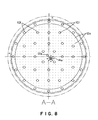
- Fig. 8 is a sectional view taken along A-A line of Fig. 7, and Fig. 9 is a sectional view taken along B-B line of Fig. 7.
- a numeral sign 101 indicates bolts. The bolts 101 fasten the middle plate 10b and the lower plate 10c. Arrows in Fig. 9 indicate flow directions of gas supplied from the second gas-passage 12b into the space 11b.
- slits 212b as gas-discharging-holes are formed on right and left sides at a lower end of the second gas-passage 12b.
- the direction in which the slits 212b are formed may be not only a right and left direction but also a vertical direction or a diagonal direction.
- discharging holes may be formed.
- the diameter of each discharging hole is preferably 1.0 to 3.0 mm, in particular 2.0 mm.
- the number of the discharging holes is optional.
- a flange 14 is commonly welded to respective base ends of the first gas-introducing-pipe 14a and the second gas-introducing-pipe 14b, which are connected to the upper plate 10a.
- An insulating member 24 including a first gas-passage 24a and a second gas-passage 24b is connected to the flange 14.
- a gas introducing member 26 including a first gas-passage 26a and a second gas-passage 26b is connected to the other end of the insulating member 24. Then, the gas introducing member 26 is connected to an upper surface of the lid member 15.
- the lid member 15 and the chamber 2 have, respectively, a first gas-passage 15a, 2a and a second gas-passage 15b, 2b.
- the first gas-passages 24a, 26a, 15a and 2a and the second gas-passages 24b, 26b, 15b and 2b from the flange 14 to the chamber 2 are, respectively, communicated in series, and sealing rings such as O-rings are interposed at connecting portions thereof.
- a first gas pipe 25a is connected to the first gas-passage 2a in the chamber 2
- a second gas pipe 25b is connected to the second gas-passage 2b.
- the respective base ends of the gas pipes 25a and 25b are connected to a gas supplying part 30.
- the gas supplying part 30 has: a ClF 3 gas source 31 that supplies ClF 3 gas, which is a cleaning gas; a TiCl 4 gas source 32 that supplies TiCl 4 gas, which is a film-forming gas; an Ar gas source 33 that supplies Ar gas, which is a carrier gas; a H 2 gas source 34 that supplies H 2 gas, which is a reduction gas; and a NH 3 gas source 35 that supplies NH 3 gas, which is used for nitriding a Ti film.
- the ClF 3 gas source 31, the TiCl 4 gas source 32 and the Ar gas source 33 are respectively connected to gas pipes 36, 37 and 38.
- the gas pipes 36, 37 and 38 are connected to the second gas pipe 25b.
- the H 2 gas source 34 and the NH 3 gas source 35 are respectively connected to gas pipes 39, 40.
- the gas pipes 39 and 40 are connected to the first gas pipe 25a.
- the respective gases from the ClF 3 gas source 31, the TiCl 4 gas source 32 and the Ar gas source 33 arrive in the second gas-passage 12b of the middle plate 10b of the showerhead 10, through the gas pipe 25b, the second gas-passages 2b, 15b, 26b and 24b of the above respective members and the gas-introducing-pipe 14b. Then, the respective gases are introduced into the space 11b, and discharged out from the second gas-discharging-holes 13b of the lower plate 10c.
- the respective gases from the H 2 gas source 34 and the NH 3 gas source 35 are introduced in the space 11a of the showerhead 10, through the gas pipe 25a, the first gas-passages 2a, 15a, 26a and 24a of the above respective members and the gas-introducing-pipe 14a. Then, the respective gases are discharged out from the first gas-discharging-holes 13a of the lower plate 10c through the first gas-passages 12a of the middle plate 10b.
- the TiCl 4 gas and the H 2 gas are not mixed with each other on the way to be supplied, but mixed after discharged into the chamber 2.
- Plasma is generated, a predetermined reaction is produced, and a Ti film is deposited on the semiconductor wafer W.
- a mass-flow controller 41 and a pair of opening/closing valves 42 and 43, between which the mass-flow controller 41 is sandwiched, are provided in each gas pipe 36, 37, 38, 39, 40 from each gas source.
- the gas supplying part 30 includes an N 2 gas source, another pipe, and another opening/closing valve and so on, which are not shown.
- the gases supplied into the spaces 11a and 11b may be changed by changing the gas sources connected to the first gas-passage 26a and the second gas-passage 26b, which are formed in the gas introducing member 26.
- a lid member 15 having an opening is mounted on an upper side of the chamber 2.
- a circular insulating member 16 is mounted on an inside peripheral portion of the lid member 15.
- the supporting portion 10e of the upper plate 10a is supported by the insulating member 16.
- An upper portion of the supporting portion 10e is covered by a circular insulating member 21 for the purpose of heat insulation.
- the insulating member 21 is supported by the lid member 15.
- the insulating member 16 has an effect of electrical insulation between the showerhead 10 and the chamber 2 and an effect of heat (thermal) insulation. Sealing rings such as O-rings are respectively interposed between the chamber 2 and the lid member 15, between the lid member 15 and the insulating member 16, and between the insulating member 16 and the supporting portion 10e. Thus, a sealed state is formed.
- An inside heater 17 is arranged on an upper surface of the horizontal portion 10d of the upper plate 10a, correspondingly to the whole surface of the semiconductor wafer W placed on the pedestal 3.
- the inside heater 17 may be formed by sandwiching a thin plate-like heater member between mica insulating plates.
- a circular (doughnut-like) outside heater 18, for example a sheath heater, is fitted so as to surround an outside periphery of the inside heater 17.
- Fig. 14 shows a structure wherein the same heater as the inside heater 17 is arranged as an outside heater.
- These heaters function as elements of a showerhead-temperature controlling unit, which is explained below.
- a space 19 is provided above the inside heater 17.
- a heat insulating member 20 is arranged above the space 19.
- the heat insulating member 20 may be a ceramics resin such as Al 2 O 3 or the like.
- the heat insulating member 20 has a cooling-gas passage 20a and a discharging port 20b.
- a dry-air supplying pipe 61a for cooling an inside portion is connected to an upper portion of the cooling-gas passage 20a.
- a dry-air supplying pipe 61b for cooling an outside portion is arranged above the supporting portion 10e of the upper plate 10a.
- the pipe 61b has a pipe portion 61c along an inside periphery of the insulating member 21.
- a large number of jetting-holes for jetting out dry air are uniformly and downwardly provided at the pipe portion 61c.
- the jetted dry air is supplied into a gap between the insulating member 16 and the heat insulating member 20 and its vicinity, so as to cool the outside heater and its vicinity.
- a power supply line 45 is connected to an upper surface of the upper plate 10a of the showerhead 10.
- the power supply line 45 is connected to a high-frequency electric power source 47 via a matching unit 46. Then, a high-frequency electric power is supplied from the high-frequency electric power source 47 to the showerhead 10. Thus, a high-frequency electric field is formed, the process gas supplied into the chamber 2 is made plasma, and the film-forming reaction is promoted.
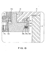
- a circular filler 48 made of quartz is provided so as to prevent that plasma is generated around a lower portion of the showerhead 10, especially in a space surrounded by lateral surfaces of the upper plate 10a, the middle plate 10b and the lower plate 10c, a lower surface of the insulating member 16, a lower surface of the lid member 15 and a side wall of the chamber 2.
- the filler 48 has a concave portion 48a at an outside portion thereof. Convex portions 49a of a plurality of supporting members 49 fastened to the lid member 15 by means of screws are fitted in the concave portion 48a to support the filler 48.
- An elastic (resilient) member 50 such as a fluoro rubber is interposed between a lateral surface of the concave portion 48a of the filler 48 and a lateral surface of each convex portion 49a of each supporting member 49. Because of the elastic member 50, centering of the showerhead 10 can be easily achieved and the filler 48 can be simply attached and removed. In addition, breakage of the filler 48 caused by thermal expansion and contraction can be prevented.
- An elastic (resilient) member 51 is interposed between the filler 48 and the lid member 15. The elastic member 51 also has a function of preventing the breakage of the filler 48.
- An exhaust pipe 52 is connected to a side wall at a base portion of the cylindrical pedestal supporting member 7 attached at a base portion of the chamber 2.
- An exhaust unit 53 is connected to the exhausting pipe 52.
- the chamber 2 can be evacuated.
- a unit that traps unreacted materials and/or by-products is not shown but provided on an upstream side with respect to the exhausting unit 53.
- the chamber 2 can be vacuumed to a predetermined vacuum level by driving the exhausting unit 53.
- a sealed box 23 is provided over the lid member 15.
- An exhausting port 54 is provided at an upper portion of the sealed box 23. Inside heated dry air and outside heated dry air in the sealed box 23 are adapted to be exhausted from the exhausting port 54.
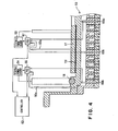
- the CVD film-forming apparatus 1 has a showerhead-temperature controlling unit 60 that controls a temperature of the showerhead 10.
- the showerhead-temperature controlling unit 60 is explained hereinafter.
- the showerhead-temperature controlling unit 60 has: the inside heater 17 and the outside heater 18, which are described above as a heating mechanism; the dry-air supplying pipes 61a and 61b for supplying dry air as a cooling mechanism; a temperature-detecting mechanism consisting of thermocouples 65a, 65b, 66a and 66b that monitor temperatures of the inside heater 17, the outside heater 18 and the lower plate 10d of the showerhead 10; and a controller 62 that controls the above elements.
- thermocouple 65a for detecting the temperature contacts with an insulating sheet 131 of high thermal conductivity on the upper plate, and the thermocouple 65b contacts with the inside of the lower plate.
- thermocouple 66a for detecting the temperature of the outside portion of the upper plate 10a contacts with the inside of the upper plate and the thermocouple 66b for detecting the temperature of the outside portion of the lower plate 10c contacts with the inside of the lower plate.
- Each thermocouple 65a, 65b, 66a, 66b may be a plurality of thermocouples.
- an inside-temperature controller 67 that controls the temperature by means of a PID control to the output of the inside heater 17, based on an instruction of the controller 62 and a signal detected by the thermocouple 65a or 65b
- an outside-temperature controller 68 that controls the temperature by means of a PID control to the output of the outside heater 18 or the like, based on an instruction of the controller 62 and a signal detected by the thermocouple 66a or 66b.
- the dry air supplied from the dry-air supplying pipe 61a is introduced into the space 19 through the cooling-gas passage 20a of the heat insulating member 20, as a cooling material.
- the dry air takes heat emitted from the inside heater 17 into the space 19, flows through the exhausting port 20b, and is exhausted from the exhausting port 54 of the sealed box 23 provided on the upper portion of the lid member 15.
- the dry air supplied from the dry-air supplying pipe 61b is discharged out from the discharging-holes on the lower side of the pipe, takes heat in the outside portion of the showerhead including the outside heater 18 or the like, and is exhausted from the exhausting port 54 of the sealed box 23.
- Air operation valves 69a and 69b are respectively provided in the dry-air supplying pipes 61a and 61b.
- the air operation valves 69a and 69b are controlled by the controller 62.
- a preferable temperature control can be achieved in accordance with a control shown in Fig. 5.
- a set temperature is set at the controller 62.
- the temperature controller 67 controls the output of the inside heater 17 in such a manner that a temperature detected by the thermocouple 65a or 65b coincides with the set temperature.
- the value detected by the thermocouple 65a or 65b is also outputted to the temperature controller 68 via the controller 62.
- the temperature controller 68 controls the output of the outside heater 18 in such a manner that the difference between a temperature detected by the thermocouple 66a or 66b at the position corresponding to the outside heater 18 and a temperature detected by the thermocouple 65a or 65b at the position corresponding to the inside heater 17 coincides with zero. Therefore, the temperature of the outside portion of the showerhead 10 and the temperature of the inside portion of the showerhead 10 are controlled to be substantially the same.
- thermocouples 65b and 66b of the showerhead-temperature controlling unit 60 are arranged in the showerhead, which can be a vacuum. However, the other elements are arranged in the atmospheric air.
- the showerhead 10 can be inverted outwardly from the chamber 2 by an inverting mechanism 80 having a hinge mechanism.
- the showerhead 10 can be positioned substantially completely outside the chamber 2 in such a manner that the gas-discharging surface is directed upward.
- maintenance of the showerhead 10 can be very easily conducted.
- the plurality of supporting members 49 can be easily taken out outwardly by removing the fastening screws (arrow (1)). After the supporting members 49 are taken out, the filler 48 can be easily taken out upwardly (arrow (2)). Then, after the filler 48 is taken out, maintenance of the showerhead 10 itself can be conducted.
- the lower plate 10c and the middle plate 10b can be easily taken out upwardly (arrow (3)).
- the showerhead 10 is held at a position inverted by 180 degrees. It is sufficient that the inverted degrees are around 180 degrees.
- a gas spring or the like can be used.
- a processing operation of the CVD film-forming apparatus 1 as structured above is explained.
- a pre-coated film is formed on the surfaces of the showerhead 10 and the pedestal 3 and so on in accordance with the following steps.
- the chamber 2 is exhausted by the discharging unit 53, a predetermined gas is introduced into the chamber 2 at a predetermined flow rate, and the inside of the chamber 2 becomes a predetermined pressure.
- a film-forming gas which includes H 2 gas, Ticl 4 gas and other gases, is introduced into the chamber 2 at a predetermined flow rate, and a high-frequency electric power is supplied from the high-frequency electric power source 47 to the showerhead 10, so that plasma is generated in the chamber 2.
- a Ti film is deposited on the showerhead 10 and the pedestal 3 and so on.
- the supply of the electric power from the high-frequency electric power source 47 and the supply of the TiCl 4 gas are stopped.
- NH 3 gas and other gases are supplied at predetermined flow rates, and again the high-frequency electric power is supplied from the high-frequency electric power source 47 to the showerhead 10, so that plasma is generated.
- a surface of the deposited Ti film is nitrided, so that a stable pre-coated film is formed on the showerhead 10 and pedestal 3 and so on.
- a gate valve not shown is opened, and a semiconductor wafer W is conveyed into the chamber 2 and placed onto the pedestal 3. Then, the H 2 gas, the Ticl 4 gas and the other gases are supplied at predetermined flow rates, and a high-frequency electric power is supplied from the high-frequency electric power source 47 to the showerhead 10, so that plasma is generated in the chamber 2. Thus, a Ti film is deposited on the semiconductor wafer W. Then, the supply of the electric power from the high-frequency electric power source 47 and the supply of the TiCl 4 gas are stopped.
- the NH 3 gas and the other gases are supplied at predetermined flow rates, and again the high-frequency electric power is supplied from the high-frequency electric power source 47 to the showerhead 10, so that plasma is generated.
- the Ti film deposited on the semiconductor wafer W is nitrided.
- the supply of the electric power from the high-frequency electric power source 47 and the supply of the NH 3 gas are stopped.
- the film-forming process is completed as described above, the processed semiconductor wafer W is conveyed out from the chamber 2, another semiconductor wafer W to be successively processed is conveyed into the chamber, and the same film-forming process is conducted to the latter semiconductor wafer W.
- the pedestal 3 and the showerhead 10 are cooled to a predetermined temperature, and ClF 3 gas as a cleaning gas is supplied into the chamber 2 in order to conduct a cleaning process.
- the following effects can be achieved because the showerhead 10 is provided with the showerhead-temperature controlling unit 60.
- the TiCl x has to be volatilized in order to form a stable film on the showerhead.
- the conventional showerhead is passively heated by the heater in the pedestal, there is no certification of that the conventional showerhead is heated to or over 425 °C.
- a stable pre-coated film may not be formed on the showerhead.
- the showerhead 10 is provided with the showerhead-temperature controlling unit 60, so that the showerhead 10 can be actively heated to or over 425 °C.
- a gas including the NH 3 gas so as to reduce and nitride TiCl x , a stable pre-coated film can be surely formed on the showerhead 10.
- the showerhead 10 when the inside of the chamber 2 is heated to a film-forming temperature, if the showerhead 10 is heated only by radiant heat from the pedestal 3 like a conventional manner, it takes a long time for the temperature of the showerhead 10 to become stable at a predetermined heating temperature.
- the showerhead 10 in addition to being passively heated by the heater 6 of the pedestal 3, the showerhead 10 is in advance actively heated by the heaters 17 and 18 that are elements of the showerhead-temperature controlling unit 60.
- the whole showerhead 10 is heated, so that the temperature of a surface of the lower plate of the showerhead 10 can be stabilized to a constant temperature.
- the temperature in the chamber 2 can be stabilized to a predetermined temperature within a short time.
- the temperature of the showerhead 10 is controlled uniformly, the Ti film can be formed uniformly on the semiconductor wafer W. Especially, when a semiconductor wafer is enlarged to 300 mm and thus the apparatus is also enlarged, the above effect is remarkable.
- the high-frequency electric power source is turned off.
- the temperature of the heater in the pedestal was set higher.
- the temperature of the showerhead 10 is controlled by the showerhead-temperature controlling unit 60, the temperature of the showerhead 10 can be maintained and stabilized at a predetermined temperature, even during an idling state.
- the temperature of the showerhead 10 has to be lowered from the film-forming temperature to a cleaning temperature of 200 to 300 °C.
- heat-radiating performance of the showerhead was so poor that it took a long time for the temperature to fall down.
- dry air as a cooling medium is supplied to the upper portion of the showerhead 10 through the dry-air supplying pipes 61a and 61b by the showerhead-temperature controlling unit 60, in order to cool the showerhead.
- the inside temperature of the chamber 2 can be fast lowered to a cleaning temperature.
- the upper part of the upper plate 10a of the showerhead 10 is exposed to atmospheric air.
- almost all the elements of the showerhead-temperature controlling unit 60 can be disposed inside atmosphere. Therefore, it is easy to handle the showerhead-temperature controlling unit 60.
- the inside heater 17 and the outside heater 18 are provided as a heating mechanism of the showerhead-temperature controlling unit 60, in order to achieve a two-zone control. Then, as shown in Fig. 4, the output of the inside heater 17 is controlled by the temperature controller 67 in such a manner that a temperature detected by the thermocouple 65a or 65b coincides with a set temperature, and the output of the outside heater 18 is controlled by the temperature controller 68 in such a manner that the difference between a temperature detected by the thermocouple 66a or 66b located correspondingly to the outside heater 18 and the temperature detected by the thermocouple 65a or 65b located correspondingly to the inside heater 17 coincides with zero, so that the inside portion and the outside portion of the showerhead 10 are controlled to be always at the same temperature.
- heat dissipation from the outside portion of the showerhead 10 can be inhibited, so that temperature controlling performance can be enhanced.
- the above two-zone control is more effective.
- the showerhead 10 is inverted outwardly from the chamber 2 by the inverting mechanism 8.
- the maintenance of the showerhead 10 can be conducted while the gas-discharging surface of the showerhead 10 is directed upward. That is, the maintenance of the showerhead 10 can be conducted very easily.
- the plurality of supporting members 49 are taken out outwardly.
- the filler 48 is taken out upwardly.
- the lower plate 10c and the middle plate 10b of the showerhead 10 are taken out upwardly.
- each operation for taking-out each element is so easy that the maintenance of the showerhead 10 can be conducted very easily.
- This invention is not limited to the above embodiment, but may be variably modified within a scope of spirit of the invention.
- the film-forming process of a Ti film is explained in the above embodiment, this invention is not limited thereto, but applicable to a CVD film-forming process of another film such as a TiN film.
- the plasma is not necessary.
- the showerhead-temperature controlling unit is also not limited to the above structure.
- the controlling method is also not limited to the above method.
- the dry air is used as a cooling medium, another gas such as Ar or N 2 can be also used. If plasma is not used, liquid such as water or coolant can be used as a cooling medium.
- the process to the semiconductor wafer is explained, this invention is not limited thereto, but also applicable to a process to another substrate such as a Liquid-Crystal-Display glass substrate.
- the second gas-supplying portion 12 communicating with the second gas-passage 12b is arranged in the substantially central portion of the space 11b formed below the middle plate.
- the openings 12c are formed on the lateral sides of the gas-supplying portion 12.
- the gas supplied through the second gas-passage 12b may not be sufficiently uniformly diffused into the space 11b of the middle plate 10c.
- one or more gas-diffusion promoting pipes are connected to the openings 12c of the second gas-discharging portion 12 arranged in the substantially central portion of the space 11b.
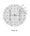
- a substantially H-shaped gas-diffusion promoting pipe 110 is arranged in the space 11b below the middle plate 10c in order to uniformly diffuse the second gas.
- the central portion of the substantially H-shaped gas-diffusion promoting pipe 110 is connected to and fitted in the second gas-discharging portion 12.
- Gas-discharging holes 110a are formed at four tip portions of the gas-diffusion promoting pipe 110.
- the gas-diffusion promoting pipe 110 is formed integratedly by welding.
- Supporting pillars 110b that supports the gas-diffusion promoting pipe 110 are fixed to the middle plate 10b and the upper surface of the lower plate 10c, in order to prevent motion of the gas-diffusion promoting pipe 110.
- the gas-discharging holes 110a formed at the respective tip portions are open toward the upper plate, so that the gas supplied through the second gas-discharging portion 12 can be sufficiently uniformly diffused into the space 11b.
- Arrows in Fig. 10 schematically show flows of the gas supplied from the gas-discharging holes 110a into the space 11b.
- the shape, the orientation and the position of the gas-diffusion promoting pipe 110, the number of gas-discharging holes 110a and the manner of openings are not limited, if the gas supplied through the second gas-passage 12b can be diffused sufficiently uniformly into the space 11b.
- the gas-discharging holes 110a may be formed to open to a lateral direction.
- the gas-discharging holes 110a may be formed uniformly on the way to the tip ends of the pipe, preferably uniformly in the space 11b.
- Fig. 11 shows a sectional view of the middle plate 10b attached to the lower plate 10c and the gas-diffusion promoting pipe 110 shown in Fig. 10.
- Fig. 11 shows a section piercing a central pipe 110c of the gas-diffusion promoting pipe 110 basically, but shows a section piercing a gas-discharging hole 110a at a right-end portion of the gas-diffusion promoting pipe 110.
- Figs. 12 and 13 show a variant regarding the control system.
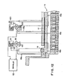
- Fig. 12 is a schematic view showing the variant at a portion corresponding to the heating mechanism of Fig. 4, and Fig. 13 is a view showing the variant of the controlling manner of Fig. 5.
- noise filters 120 are provided between the control system and the respective thermocouples 65a, 65b, 66a and 66b, and between the control system and the respective heaters 17 and 18. Preferably, they are arranged nearer to the control system. Providing the noise filters 120 like this is effective in removing noises from the high-frequency electric power source 47 to improve the controlling performance.
- a flat doughnut-like outside heater 118 is provided instead of the circular outside heater 18 having a circular section.
- the shape of the heater is not limited in particular.
- an insulating sheet 131 is formed between the inside heater 17 and the upper plate 10a, and an insulating sheet 132 is similarly formed between the outside heater 118 and the upper plate 10a.
- the thickness of the respective insulating sheets 131 is a degree not affected by noises, for example 0.5 mm to 1.0 mm.
- the upper plate 10a functions as an electrode for generating plasma, so that the insulating sheets 131 and 132 are preferably thick in order to inhibit effects of the noises that the heaters receive.
- the insulating sheets 131 and 132 have to have high heat conductivity and high heat resistance.
- ceramics such as aluminum nitride is suitable as a material of the insulating sheets 131 and 132.
- a corrosion-resisting metal spring for example an elastic member 150 made of a Ni-alloy such as inconel, is provided.
- an elastic member 150 made of a Ni-alloy such as inconel.
- the manner of an elastic member interposed between the lateral surface of the concave portion 48a of the filler 48 and the lateral surface of the convex portion 49a of the supporting member 49 is not limited in particular.
Landscapes
- Chemical & Material Sciences (AREA)
- Engineering & Computer Science (AREA)
- Chemical Kinetics & Catalysis (AREA)
- General Chemical & Material Sciences (AREA)
- Materials Engineering (AREA)
- Mechanical Engineering (AREA)
- Metallurgy (AREA)
- Organic Chemistry (AREA)
- Plasma & Fusion (AREA)
- Analytical Chemistry (AREA)
- Physics & Mathematics (AREA)
- Chemical Vapour Deposition (AREA)
- Electrodes Of Semiconductors (AREA)
Abstract
Description
| Temperature of showerhead | Temperature of pedestal | Operation Operation | |
| Prior art | 470~480°C | 640~650°C | Temperature of pedestal has to be raised not lower than film-forming temperature |
| Invention | 500°C | 640°C | Temperature of showerhead controlled |
Claims (19)
- A film-forming apparatus comprising:a processing container that defines a chamber,a pedestal arranged in the chamber, on which a substrate to be processed can be placed,a showerhead provided opposite to the pedestal, which has a large number of gas-discharging holes,a gas-supplying mechanism that supplies a process gas into the chamber through the showerhead, anda showerhead-temperature controlling unit that controls a temperature of the showerhead.
- A film-forming apparatus according to claim 1, wherein
the processing container is formed in such a manner that the processing container can be vacuumed. - A film-forming apparatus according to claim 1 or 2, further comprising
a heating unit that heats the pedestal. - A film-forming apparatus according to any of claims 1 to 3, wherein
the showerhead has: a chamber-inside part that includes a surface in which the large number of gas-discharging holes appear, and an atmosphere-side part that contacts with atmospheric air outside the chamber, and
the showerhead-temperature controlling unit is provided in the atmosphere-side part. - A film-forming apparatus according to any of claims 1 to 4, further comprising
a second heating unit that heats the chamber. - A film-forming apparatus according to any of claims 1 to 5, wherein
the showerhead-temperature controlling unit includes:a heating mechanism that heats the showerhead,a cooling mechanism that cools the showerhead,a temperature-detecting mechanism that detects a temperature of the showerhead, anda controller that controls at least the heating mechanism, based on a result detected by the temperature-detecting mechanism. - A film-forming apparatus according to claim 6, wherein
the heating mechanism has:the temperature detecting mechanism has:an inside heater that heats an inside portion of the showerhead, andan outside heater that heats an outside portion of the showerhead, andan inside-temperature detecting part that detects a temperature of the inside portion, andan outside-temperature detecting part that detects a temperature of the outside portion. - A film-forming apparatus according to claim 7, wherein
the controller is adapted to control the inside heater in such a manner that a value detected by the inside-temperature detecting part coincides with a set temperature, and to control the outside heater in such a manner that a difference between a value detected by the outside-temperature detecting part and the value detected by the inside-temperature detecting part coincides with zero. - A film-forming apparatus according to any of claims 1 to 8, wherein
a thermal-insulating member is arranged on a surface of the showerhead reverse to the chamber. - A film-forming apparatus according to any of claims 1 to 9, wherein
the showerhead has: a showerhead body, and a circular supporting part continued upward from on an outside periphery of the showerhead body, and
the supporting part has a rib structure. - A film-forming apparatus according to claim 10, wherein
an insulating member is arranged on the showerhead body and inside the supporting part. - A film-forming apparatus according to any of claims 1 to 11, wherein
a circular infilling member and a fixing member for fixing the infilling member to the showerhead or the processing container are arranged between the showerhead and the processing container. - A film-forming apparatus according to claim 12, wherein
a resilient member is interposed between the infilling member and the fixing member. - A film-forming apparatus according to any of claims 1 to 13, further comprising
a plasma-generating unit for generating plasma of the process gas in the chamber. - A film-forming apparatus according to any of claims 1 to 14, further comprising
an inverting mechanism that inverts the showerhead by turning the showerhead outwardly from the chamber. - A film-forming apparatus comprising:a processing container that defines a chamber,a pedestal arranged in the chamber, on which a substrate to be processed can be placed,a showerhead provided opposite to the pedestal, which has a large number of gas-discharging holes,a gas-supplying mechanism that supplies a process gas into the chamber through the showerhead, andan inverting mechanism that inverts the showerhead by turning the showerhead outwardly from the chamber.
- A film-forming apparatus according to claim 16, wherein
a circular infilling member and a fixing member for fixing the infilling member to the showerhead or the processing container are arranged between the showerhead and the processing container. - A film-forming apparatus according to claim 17, wherein
a resilient member is interposed between the infilling member and the fixing member. - A film-forming apparatus according to claim 18, wherein
the fixing member is outwardly removable in a state wherein the showerhead is inverted, and
the infilling member is upwardly removable in a state wherein the fixing member has been outwardly removed.
Applications Claiming Priority (3)
| Application Number | Priority Date | Filing Date | Title |
|---|---|---|---|
| JP2001034520 | 2001-02-09 | ||
| JP2001034520 | 2001-02-09 | ||
| PCT/JP2002/001110 WO2002063065A1 (en) | 2001-02-09 | 2002-02-08 | Film forming device |
Publications (3)
| Publication Number | Publication Date |
|---|---|
| EP1371751A1 true EP1371751A1 (en) | 2003-12-17 |
| EP1371751A4 EP1371751A4 (en) | 2005-09-07 |
| EP1371751B1 EP1371751B1 (en) | 2011-08-17 |
Family
ID=18898113
Family Applications (1)
| Application Number | Title | Priority Date | Filing Date |
|---|---|---|---|
| EP02711435A Expired - Lifetime EP1371751B1 (en) | 2001-02-09 | 2002-02-08 | Film forming device |
Country Status (5)
| Country | Link |
|---|---|
| US (4) | US7661386B2 (en) |
| EP (1) | EP1371751B1 (en) |
| JP (1) | JP4889683B2 (en) |
| KR (12) | KR100756107B1 (en) |
| WO (1) | WO2002063065A1 (en) |
Cited By (2)
| Publication number | Priority date | Publication date | Assignee | Title |
|---|---|---|---|---|
| WO2006104687A1 (en) * | 2005-03-25 | 2006-10-05 | Tokyo Electron Limited | Load bearing insulator in vacuum etch chamber |
| CN1669796B (en) * | 2004-02-23 | 2012-05-23 | 周星工程股份有限公司 | Device for manufacturing display basic board and blow head combination assemblaging therein |
Families Citing this family (106)
| Publication number | Priority date | Publication date | Assignee | Title |
|---|---|---|---|---|
| KR100756107B1 (en) * | 2001-02-09 | 2007-09-05 | 동경 엘렉트론 주식회사 | Deposition device |
| TWI224815B (en) * | 2001-08-01 | 2004-12-01 | Tokyo Electron Ltd | Gas processing apparatus and gas processing method |
| JP4121269B2 (en) * | 2001-11-27 | 2008-07-23 | 日本エー・エス・エム株式会社 | Plasma CVD apparatus and method for performing self-cleaning |
| KR100455430B1 (en) * | 2002-03-29 | 2004-11-06 | 주식회사 엘지이아이 | Cooling apparatus for surface treatment device of heat exchanger and manufacturing method thereof |
| JP3574651B2 (en) * | 2002-12-05 | 2004-10-06 | 東京エレクトロン株式会社 | Film forming method and film forming apparatus |
| US20040237889A1 (en) * | 2003-05-28 | 2004-12-02 | Winbond Electronics Corporation | Chemical gas deposition process and dry etching process and apparatus of same |
| KR100527048B1 (en) * | 2003-08-29 | 2005-11-09 | 주식회사 아이피에스 | Method for depositing thin film on wafer |
| KR20060064067A (en) * | 2003-09-03 | 2006-06-12 | 동경 엘렉트론 주식회사 | Heat dissipation method of gas processing apparatus and processing gas discharge mechanism |
| US20050050708A1 (en) * | 2003-09-04 | 2005-03-10 | Taiwan Semiconductor Manufacturing Co., Ltd. | Embedded fastener apparatus and method for preventing particle contamination |
| JP4513329B2 (en) | 2004-01-16 | 2010-07-28 | 東京エレクトロン株式会社 | Processing equipment |
| US20050230350A1 (en) * | 2004-02-26 | 2005-10-20 | Applied Materials, Inc. | In-situ dry clean chamber for front end of line fabrication |
| US7712434B2 (en) * | 2004-04-30 | 2010-05-11 | Lam Research Corporation | Apparatus including showerhead electrode and heater for plasma processing |
| JP4659820B2 (en) * | 2005-03-07 | 2011-03-30 | シャープ株式会社 | Plasma processing apparatus and semiconductor thin film manufacturing method using the same |
| US20070210182A1 (en) * | 2005-04-26 | 2007-09-13 | Spraying Systems Co. | System and Method for Monitoring Performance of a Spraying Device |
| US20060237556A1 (en) * | 2005-04-26 | 2006-10-26 | Spraying Systems Co. | System and method for monitoring performance of a spraying device |
| JP5044931B2 (en) * | 2005-10-31 | 2012-10-10 | 東京エレクトロン株式会社 | Gas supply apparatus and substrate processing apparatus |
| JP2007146252A (en) * | 2005-11-29 | 2007-06-14 | Tokyo Electron Ltd | Heat treatment method, heat treatment apparatus and storage medium |
| CN101310040B (en) * | 2006-02-24 | 2011-08-17 | 东京毅力科创株式会社 | Manufacturing method of ti system film |
| KR100755753B1 (en) * | 2006-03-30 | 2007-09-05 | 주식회사 아이피에스 | Shower head heating unit and thin film deposition apparatus using the same |
| JP5045000B2 (en) * | 2006-06-20 | 2012-10-10 | 東京エレクトロン株式会社 | Film forming apparatus, gas supply apparatus, film forming method, and storage medium |
| KR101206725B1 (en) | 2006-07-26 | 2012-11-30 | 주성엔지니어링(주) | Substrate processing apparatus in which buffer insulator is insulted in gap between different potential surfaces |
| KR101339201B1 (en) * | 2006-08-14 | 2013-12-09 | 주식회사 원익아이피에스 | Unit for measuring temperature and Apparatus using the same |
| KR100791010B1 (en) * | 2007-01-12 | 2008-01-03 | 삼성전자주식회사 | Semiconductor manufacturing apparatus and processing method of semiconductor substrate using same |
| CN102174693B (en) * | 2007-01-12 | 2014-10-29 | 威科仪器有限公司 | Gas treatment systems |
| US8375890B2 (en) * | 2007-03-19 | 2013-02-19 | Micron Technology, Inc. | Apparatus and methods for capacitively coupled plasma vapor processing of semiconductor wafers |
| US20080236614A1 (en) * | 2007-03-30 | 2008-10-02 | Hitachi High-Technologies Corporation | Plasma processing apparatus and plasma processing method |
| US20080237184A1 (en) * | 2007-03-30 | 2008-10-02 | Mamoru Yakushiji | Method and apparatus for plasma processing |
| US8419854B2 (en) * | 2007-04-17 | 2013-04-16 | Ulvac, Inc. | Film-forming apparatus |
| KR100920417B1 (en) * | 2007-08-01 | 2009-10-14 | 주식회사 에이디피엔지니어링 | Sensing unit and substrate processing apparatus having same |
| JP5141155B2 (en) * | 2007-09-21 | 2013-02-13 | 東京エレクトロン株式会社 | Deposition equipment |
| US8673080B2 (en) * | 2007-10-16 | 2014-03-18 | Novellus Systems, Inc. | Temperature controlled showerhead |
| US7976631B2 (en) * | 2007-10-16 | 2011-07-12 | Applied Materials, Inc. | Multi-gas straight channel showerhead |
| KR101553423B1 (en) * | 2007-12-19 | 2015-09-15 | 램 리써치 코포레이션 | Film adhesive for semiconductor vacuum processing apparatus |
| KR101553422B1 (en) * | 2007-12-19 | 2015-09-15 | 램 리써치 코포레이션 | A composite showerhead electrode assembly for a plasma processing apparatus |
| JP5039576B2 (en) * | 2008-01-11 | 2012-10-03 | シャープ株式会社 | Plasma processing equipment |
| JP5223377B2 (en) * | 2008-02-29 | 2013-06-26 | 東京エレクトロン株式会社 | Electrode for plasma processing apparatus, plasma processing apparatus and plasma processing method |
| JP4558810B2 (en) * | 2008-02-29 | 2010-10-06 | 富士フイルム株式会社 | Deposition equipment |
| FR2930561B1 (en) * | 2008-04-28 | 2011-01-14 | Altatech Semiconductor | DEVICE AND METHOD FOR CHEMICAL TREATMENT IN STEAM PHASE. |
| US8161906B2 (en) * | 2008-07-07 | 2012-04-24 | Lam Research Corporation | Clamped showerhead electrode assembly |
| KR20110079831A (en) * | 2008-10-03 | 2011-07-08 | 비코 프로세스 이큅먼트, 아이엔씨. | Weather epitaxy system |
| KR101680751B1 (en) * | 2009-02-11 | 2016-12-12 | 어플라이드 머티어리얼스, 인코포레이티드 | Non-contact substrate processing |
| WO2010114118A1 (en) * | 2009-04-03 | 2010-10-07 | 東京エレクトロン株式会社 | Deposition head and film forming apparatus |
| KR101036454B1 (en) | 2009-06-08 | 2011-05-24 | 주식회사 테스 | Large Area Gas Injection Device |
| US20110061812A1 (en) * | 2009-09-11 | 2011-03-17 | Applied Materials, Inc. | Apparatus and Methods for Cyclical Oxidation and Etching |
| US20110061810A1 (en) * | 2009-09-11 | 2011-03-17 | Applied Materials, Inc. | Apparatus and Methods for Cyclical Oxidation and Etching |
| US20110065276A1 (en) * | 2009-09-11 | 2011-03-17 | Applied Materials, Inc. | Apparatus and Methods for Cyclical Oxidation and Etching |
| WO2011044451A2 (en) * | 2009-10-09 | 2011-04-14 | Applied Materials, Inc. | Multi-gas centrally cooled showerhead design |
| US9034142B2 (en) * | 2009-12-18 | 2015-05-19 | Novellus Systems, Inc. | Temperature controlled showerhead for high temperature operations |
| USD642605S1 (en) | 2010-04-02 | 2011-08-02 | Applied Materials, Inc. | Lid assembly for a substrate processing chamber |
| US10658161B2 (en) * | 2010-10-15 | 2020-05-19 | Applied Materials, Inc. | Method and apparatus for reducing particle defects in plasma etch chambers |
| KR101609429B1 (en) * | 2010-11-05 | 2016-04-05 | 샤프 가부시키가이샤 | Oxidation/annealing treatment apparatus and process for production of thin film transistor employing oxidation/annealing treatment |
| SG192967A1 (en) | 2011-03-04 | 2013-09-30 | Novellus Systems Inc | Hybrid ceramic showerhead |
| TWI534291B (en) * | 2011-03-18 | 2016-05-21 | 應用材料股份有限公司 | Sprinkler assembly |
| JP5762798B2 (en) * | 2011-03-31 | 2015-08-12 | 東京エレクトロン株式会社 | Ceiling electrode plate and substrate processing placement |
| US10224182B2 (en) | 2011-10-17 | 2019-03-05 | Novellus Systems, Inc. | Mechanical suppression of parasitic plasma in substrate processing chamber |
| US9449795B2 (en) * | 2013-02-28 | 2016-09-20 | Novellus Systems, Inc. | Ceramic showerhead with embedded RF electrode for capacitively coupled plasma reactor |
| US9748121B2 (en) * | 2013-03-05 | 2017-08-29 | Applied Materials, Inc. | Thermal coupled quartz dome heat sink |
| TWI627305B (en) * | 2013-03-15 | 2018-06-21 | Applied Materials, Inc. | Atmospheric cover with rigid plate for turntable processing chamber |
| KR20150046966A (en) * | 2013-10-23 | 2015-05-04 | 삼성디스플레이 주식회사 | Plasma processing apparatus and plasma processing method |
| US9657397B2 (en) * | 2013-12-31 | 2017-05-23 | Lam Research Ag | Apparatus for treating surfaces of wafer-shaped articles |
| US9597701B2 (en) * | 2013-12-31 | 2017-03-21 | Lam Research Ag | Apparatus for treating surfaces of wafer-shaped articles |
| JP6379550B2 (en) | 2014-03-18 | 2018-08-29 | 東京エレクトロン株式会社 | Deposition equipment |
| KR102263827B1 (en) * | 2014-03-21 | 2021-06-14 | 삼성디스플레이 주식회사 | Oxide semiconductor depositing apparatus and method of manufacturing oxide semiconductor using the same |
| US10741365B2 (en) | 2014-05-05 | 2020-08-11 | Lam Research Corporation | Low volume showerhead with porous baffle |
| US20150361582A1 (en) * | 2014-06-17 | 2015-12-17 | Veeco Instruments, Inc. | Gas Flow Flange For A Rotating Disk Reactor For Chemical Vapor Deposition |
| KR101613864B1 (en) | 2014-10-13 | 2016-04-20 | 주식회사 테스 | Metal organic chemical vapour deposition reaction apparatus |
| US10378107B2 (en) | 2015-05-22 | 2019-08-13 | Lam Research Corporation | Low volume showerhead with faceplate holes for improved flow uniformity |
| US10023959B2 (en) | 2015-05-26 | 2018-07-17 | Lam Research Corporation | Anti-transient showerhead |
| US10487401B2 (en) * | 2015-10-02 | 2019-11-26 | Applied Materials, Inc. | Diffuser temperature control |
| KR101941488B1 (en) * | 2016-07-04 | 2019-01-23 | 세메스 주식회사 | Shower head unit and Apparatus for treating substrate with the unit |
| JP6495875B2 (en) | 2016-09-12 | 2019-04-03 | 株式会社東芝 | Flow path structure and processing apparatus |
| US10403476B2 (en) * | 2016-11-09 | 2019-09-03 | Lam Research Corporation | Active showerhead |
| FR3061914B1 (en) * | 2017-01-16 | 2019-05-31 | Kobus Sas | TREATMENT CHAMBER FOR A CHEMICAL VAPOR DEPOSITION REACTOR (CVD) AND METHOD OF THERMALIZATION IMPLEMENTED IN THIS CHAMBER |
| US10867812B2 (en) | 2017-08-30 | 2020-12-15 | Taiwan Semiconductor Manufacturing Co., Ltd. | Semiconductor manufacturing system and control method |
| JP6926233B2 (en) * | 2017-12-01 | 2021-08-25 | 東京エレクトロン株式会社 | Substrate liquid processing equipment |
| US11084694B2 (en) | 2018-03-27 | 2021-08-10 | Samsung Electronics Co., Ltd. | Jacking tool and semiconductor process apparatus having the same |
| JP2021521648A (en) * | 2018-04-17 | 2021-08-26 | アプライド マテリアルズ インコーポレイテッドApplied Materials,Incorporated | Ceramic face plate to be heated |
| US11286565B2 (en) * | 2018-12-13 | 2022-03-29 | Xia Tai Xin Semiconductor (Qing Dao) Ltd. | Apparatus and method for semiconductor fabrication |
| JP7134863B2 (en) * | 2018-12-27 | 2022-09-12 | 東京エレクトロン株式会社 | Plasma processing apparatus and plasma processing method |
| US11332827B2 (en) * | 2019-03-27 | 2022-05-17 | Applied Materials, Inc. | Gas distribution plate with high aspect ratio holes and a high hole density |
| CN111785604B (en) * | 2019-04-04 | 2025-04-08 | 中微半导体设备(上海)股份有限公司 | Gas shower head, manufacturing method and plasma device including the gas shower head |
| US20220228263A1 (en) * | 2019-06-07 | 2022-07-21 | Lam Research Corporation | Independently adjustable flowpath conductance in multi-station semiconductor processing |
| KR102268559B1 (en) * | 2019-07-03 | 2021-06-22 | 세메스 주식회사 | Shower head unit and system for treating substrate with the shower head unit |
| US10954595B2 (en) * | 2019-07-30 | 2021-03-23 | Applied Materials, Inc. | High power showerhead with recursive gas flow distribution |
| KR20260046529A (en) | 2019-08-23 | 2026-04-07 | 램 리써치 코포레이션 | Thermally controlled chandelier showerhead |
| CN119980191A (en) | 2019-08-28 | 2025-05-13 | 朗姆研究公司 | Metal Deposition |
| CN114503246A (en) * | 2019-09-13 | 2022-05-13 | 应用材料公司 | Semiconductor processing chamber |
| CN112543520B (en) * | 2019-09-20 | 2023-05-30 | 中微半导体设备(上海)股份有限公司 | Heater, heating method and plasma processor |
| WO2021053836A1 (en) | 2019-09-20 | 2021-03-25 | 株式会社Kokusai Electric | Semiconductor device manufacturing method, substrate processing device, and program |
| KR102235672B1 (en) * | 2019-12-19 | 2021-04-01 | 광운대학교 산학협력단 | Atmospheric Pressure Plasma Generation System and Method for Large Area |
| CN111321463B (en) * | 2020-03-06 | 2021-10-15 | 北京北方华创微电子装备有限公司 | Reaction chamber |
| US11242600B2 (en) * | 2020-06-17 | 2022-02-08 | Applied Materials, Inc. | High temperature face plate for deposition application |
| US12191169B2 (en) * | 2020-07-19 | 2025-01-07 | Applied Materials, Inc. | Systems and methods for faceplate temperature control |
| CN114334700A (en) * | 2020-09-29 | 2022-04-12 | 长鑫存储技术有限公司 | Installation jig of semiconductor equipment electrode plate |
| KR102699263B1 (en) * | 2021-06-29 | 2024-08-28 | (주)나노테크 | Shower head with heating function |
| JP7317083B2 (en) * | 2021-09-01 | 2023-07-28 | 株式会社Kokusai Electric | Semiconductor device manufacturing method, substrate processing apparatus, program, and substrate processing method |
| US20230073150A1 (en) * | 2021-09-09 | 2023-03-09 | Applied Materials, Inc. | Heated lid for a process chamber |
| CN114334728B (en) * | 2021-12-27 | 2025-08-29 | 拓荆科技股份有限公司 | Semiconductor process chamber |
| US12176185B2 (en) * | 2022-04-01 | 2024-12-24 | Semes Co., Ltd. | Apparatus and method for processing substrate using plasma |
| US20230352275A1 (en) * | 2022-04-29 | 2023-11-02 | Semes Co., Ltd. | Apparatus and method for processing substrate |
| CN117389101A (en) * | 2022-07-04 | 2024-01-12 | 中强光电股份有限公司 | Heat dissipation module and anti-condensation method of projection device |
| KR102760452B1 (en) * | 2022-08-02 | 2025-02-03 | 주식회사 테스 | Showerhead assembly and Substrate processing apparatus |
| JP2024051314A (en) | 2022-09-30 | 2024-04-11 | 東京エレクトロン株式会社 | COOLING APPARATUS, SUBSTRATE PROCESSING APPARATUS, AND COOLING METHOD |
| KR102893081B1 (en) * | 2023-01-12 | 2025-12-10 | 주식회사 지엠피 | Plasma enhanced chemical vapor deposition apparatus and manufacturing apparatus for electrode structure for lithium-sulfur battery |
| JP2026007621A (en) * | 2024-07-03 | 2026-01-16 | 東京エレクトロン株式会社 | Substrate processing apparatus and substrate processing method |
| USD1112390S1 (en) | 2024-07-22 | 2026-02-10 | Asm Ip Holding B.V. | Flow control ring |
Family Cites Families (68)
| Publication number | Priority date | Publication date | Assignee | Title |
|---|---|---|---|---|
| DE69130205T2 (en) * | 1990-12-25 | 1999-03-25 | Ngk Insulators, Ltd., Nagoya, Aichi | Semiconductor wafer heater and method of manufacturing the same |
| JP3283272B2 (en) * | 1991-04-30 | 2002-05-20 | 株式会社ニチレイ | Enhancer nucleic acid base sequence |
| US5447568A (en) * | 1991-12-26 | 1995-09-05 | Canon Kabushiki Kaisha | Chemical vapor deposition method and apparatus making use of liquid starting material |
| US5366585A (en) | 1993-01-28 | 1994-11-22 | Applied Materials, Inc. | Method and apparatus for protection of conductive surfaces in a plasma processing reactor |
| JP3190165B2 (en) * | 1993-04-13 | 2001-07-23 | 東京エレクトロン株式会社 | Vertical heat treatment apparatus and heat treatment method |
| US5350480A (en) * | 1993-07-23 | 1994-09-27 | Aspect International, Inc. | Surface cleaning and conditioning using hot neutral gas beam array |
| JPH07230956A (en) * | 1994-02-18 | 1995-08-29 | Kokusai Electric Co Ltd | Plasma CVD equipment |
| JP2840026B2 (en) | 1994-05-02 | 1998-12-24 | 日本エー・エス・エム株式会社 | Air-cooled processing apparatus and method for continuously processing an object to be processed using the apparatus |
| US5653806A (en) * | 1995-03-10 | 1997-08-05 | Advanced Technology Materials, Inc. | Showerhead-type discharge assembly for delivery of source reagent vapor to a substrate, and CVD process utilizing same |
| JP3360098B2 (en) * | 1995-04-20 | 2002-12-24 | 東京エレクトロン株式会社 | Shower head structure of processing equipment |
| DE69629412T2 (en) * | 1995-04-20 | 2004-06-24 | Ebara Corp. | Plant for vapor deposition of thin layers |
| JPH0930893A (en) * | 1995-05-16 | 1997-02-04 | Hitachi Electron Eng Co Ltd | Vapor phase growth equipment |
| US5698036A (en) * | 1995-05-26 | 1997-12-16 | Tokyo Electron Limited | Plasma processing apparatus |
| JPH0987090A (en) * | 1995-09-26 | 1997-03-31 | Toshiba Corp | Vapor growth method and vapor growth apparatus |
| KR100267418B1 (en) | 1995-12-28 | 2000-10-16 | 엔도 마코토 | Plasma treatment method and plasma treatment device |
| US5906683A (en) * | 1996-04-16 | 1999-05-25 | Applied Materials, Inc. | Lid assembly for semiconductor processing chamber |
| JP3310171B2 (en) | 1996-07-17 | 2002-07-29 | 松下電器産業株式会社 | Plasma processing equipment |
| KR100492258B1 (en) * | 1996-10-11 | 2005-09-02 | 가부시키가이샤 에바라 세이사꾸쇼 | Reaction gas ejection head |
| JP3649267B2 (en) * | 1996-10-11 | 2005-05-18 | 株式会社荏原製作所 | Reactive gas injection head |
| JPH10280149A (en) * | 1997-04-04 | 1998-10-20 | Ebara Corp | Gas injection device |
| KR19980071012A (en) | 1997-01-24 | 1998-10-26 | 조셉 제이. 스위니 | Method and apparatus for depositing high temperature and high deposition rate titanium films |
| US6051286A (en) | 1997-02-12 | 2000-04-18 | Applied Materials, Inc. | High temperature, high deposition rate process and apparatus for depositing titanium layers |
| JPH1167693A (en) | 1997-06-11 | 1999-03-09 | Tokyo Electron Ltd | CVD film forming apparatus and CVD film forming method |
| US6258170B1 (en) * | 1997-09-11 | 2001-07-10 | Applied Materials, Inc. | Vaporization and deposition apparatus |
| US6161500A (en) | 1997-09-30 | 2000-12-19 | Tokyo Electron Limited | Apparatus and method for preventing the premature mixture of reactant gases in CVD and PECVD reactions |
| EP1032723A1 (en) | 1997-11-17 | 2000-09-06 | Symetrix Corporation | Method and apparatus for misted deposition of thin films |
| US6106625A (en) * | 1997-12-02 | 2000-08-22 | Applied Materials, Inc. | Reactor useful for chemical vapor deposition of titanium nitride |
| US6079356A (en) | 1997-12-02 | 2000-06-27 | Applied Materials, Inc. | Reactor optimized for chemical vapor deposition of titanium |
| US6222161B1 (en) * | 1998-01-12 | 2001-04-24 | Tokyo Electron Limited | Heat treatment apparatus |
| US5997649A (en) * | 1998-04-09 | 1999-12-07 | Tokyo Electron Limited | Stacked showerhead assembly for delivering gases and RF power to a reaction chamber |
| JPH11302850A (en) | 1998-04-17 | 1999-11-02 | Ebara Corp | Gas injection device |
| KR100267885B1 (en) | 1998-05-18 | 2000-11-01 | 서성기 | Deposition apparatus |
| US6086677A (en) * | 1998-06-16 | 2000-07-11 | Applied Materials, Inc. | Dual gas faceplate for a showerhead in a semiconductor wafer processing system |
| JP3461120B2 (en) | 1998-06-29 | 2003-10-27 | 日立化成工業株式会社 | Electrode plate for plasma etching and plasma etching apparatus |
| JP2000073376A (en) * | 1998-08-31 | 2000-03-07 | Misawa Homes Co Ltd | Sheath pipe |
| KR100280519B1 (en) | 1998-11-17 | 2001-03-02 | 김영환 | Gas injection device for semiconductor organic metal chemical vapor deposition equipment |
| US20020179245A1 (en) | 1999-03-17 | 2002-12-05 | Toshio Masuda | Plasma processing apparatus and maintenance method therefor |
| JP3363405B2 (en) | 1999-03-17 | 2003-01-08 | 株式会社日立製作所 | Plasma processing apparatus and plasma processing apparatus system |
| JP3205312B2 (en) | 1999-03-17 | 2001-09-04 | 株式会社日立製作所 | Plasma processing apparatus and maintenance method for plasma processing apparatus |
| JP3595853B2 (en) * | 1999-03-18 | 2004-12-02 | 日本エー・エス・エム株式会社 | Plasma CVD film forming equipment |
| JP2000315658A (en) | 1999-04-30 | 2000-11-14 | Tokyo Electron Ltd | Heat treatment equipment |
| US20050061445A1 (en) | 1999-05-06 | 2005-03-24 | Tokyo Electron Limited | Plasma processing apparatus |
| JP4467667B2 (en) | 1999-05-21 | 2010-05-26 | 東京エレクトロン株式会社 | Plasma processing equipment |
| KR100302609B1 (en) * | 1999-05-10 | 2001-09-13 | 김영환 | Temperature controllable gas distributor |
| JP4307628B2 (en) | 1999-05-19 | 2009-08-05 | キヤノンアネルバ株式会社 | Flat plate gas introduction device for CCP reaction vessel |
| US6123775A (en) * | 1999-06-30 | 2000-09-26 | Lam Research Corporation | Reaction chamber component having improved temperature uniformity |
| US6245192B1 (en) * | 1999-06-30 | 2001-06-12 | Lam Research Corporation | Gas distribution apparatus for semiconductor processing |
| JP2001021039A (en) | 1999-07-07 | 2001-01-26 | Hitachi Kokusai Electric Inc | Semiconductor manufacturing equipment |
| KR100671359B1 (en) | 1999-07-26 | 2007-01-22 | 동경 엘렉트론 주식회사 | Method for manufacturing semiconductor device and apparatus for manufacturing same |
| JP4220075B2 (en) * | 1999-08-20 | 2009-02-04 | 東京エレクトロン株式会社 | Film forming method and film forming apparatus |
| US6772827B2 (en) * | 2000-01-20 | 2004-08-10 | Applied Materials, Inc. | Suspended gas distribution manifold for plasma chamber |
| US6432255B1 (en) * | 2000-01-31 | 2002-08-13 | Applied Materials, Inc. | Method and apparatus for enhancing chamber cleaning |
| TWI228747B (en) * | 2000-05-17 | 2005-03-01 | Tokyo Electron Ltd | Processing apparatus and the maintenance method, assembling mechanism and method of processing apparatus parts, and lock mechanism and the lock method |
| KR100756107B1 (en) * | 2001-02-09 | 2007-09-05 | 동경 엘렉트론 주식회사 | Deposition device |
| US6602800B2 (en) * | 2001-05-09 | 2003-08-05 | Asm Japan K.K. | Apparatus for forming thin film on semiconductor substrate by plasma reaction |
| US6537928B1 (en) * | 2002-02-19 | 2003-03-25 | Asm Japan K.K. | Apparatus and method for forming low dielectric constant film |
| US20030047282A1 (en) * | 2001-09-10 | 2003-03-13 | Yasumi Sago | Surface processing apparatus |
| US6827815B2 (en) * | 2002-01-15 | 2004-12-07 | Applied Materials, Inc. | Showerhead assembly for a processing chamber |
| WO2003065424A2 (en) * | 2002-01-25 | 2003-08-07 | Applied Materials, Inc. | Apparatus for cyclical deposition of thin films |
| US6901808B1 (en) * | 2002-02-12 | 2005-06-07 | Lam Research Corporation | Capacitive manometer having reduced process drift |
| US6921556B2 (en) * | 2002-04-12 | 2005-07-26 | Asm Japan K.K. | Method of film deposition using single-wafer-processing type CVD |
| US6946033B2 (en) * | 2002-09-16 | 2005-09-20 | Applied Materials Inc. | Heated gas distribution plate for a processing chamber |
| US7270713B2 (en) * | 2003-01-07 | 2007-09-18 | Applied Materials, Inc. | Tunable gas distribution plate assembly |
| US6838329B2 (en) * | 2003-03-31 | 2005-01-04 | Intel Corporation | High concentration indium fluorine retrograde wells |
| US20060213617A1 (en) * | 2005-03-25 | 2006-09-28 | Fink Steven T | Load bearing insulator in vacuum etch chambers |
| US7651568B2 (en) * | 2005-03-28 | 2010-01-26 | Tokyo Electron Limited | Plasma enhanced atomic layer deposition system |
| US20060213437A1 (en) * | 2005-03-28 | 2006-09-28 | Tokyo Electron Limited | Plasma enhanced atomic layer deposition system |
| US8163087B2 (en) * | 2005-03-31 | 2012-04-24 | Tokyo Electron Limited | Plasma enhanced atomic layer deposition system and method |
-
2002
- 2002-02-08 KR KR1020037010504A patent/KR100756107B1/en not_active Ceased
- 2002-02-08 KR KR1020067006792A patent/KR100922241B1/en not_active Expired - Fee Related
- 2002-02-08 KR KR1020097002784A patent/KR100945320B1/en not_active Expired - Fee Related
- 2002-02-08 EP EP02711435A patent/EP1371751B1/en not_active Expired - Lifetime
- 2002-02-08 KR KR1020057018178A patent/KR100676979B1/en not_active Expired - Fee Related
- 2002-02-08 KR KR1020097014511A patent/KR101004173B1/en not_active Expired - Fee Related
- 2002-02-08 WO PCT/JP2002/001110 patent/WO2002063065A1/en not_active Ceased
- 2002-02-08 KR KR1020067006790A patent/KR100735932B1/en not_active Expired - Lifetime
- 2002-02-08 KR KR1020107011259A patent/KR101004199B1/en not_active Expired - Fee Related
- 2002-02-08 KR KR1020067024611A patent/KR100776843B1/en not_active Expired - Lifetime
- 2002-02-08 KR KR1020107011258A patent/KR101004222B1/en not_active Expired - Fee Related
- 2002-02-08 US US10/467,293 patent/US7661386B2/en not_active Expired - Fee Related
- 2002-02-08 KR KR1020097002783A patent/KR100945321B1/en not_active Expired - Fee Related
- 2002-02-08 KR KR1020067018174A patent/KR100749377B1/en not_active Ceased
- 2002-02-08 KR KR1020097014512A patent/KR101004192B1/en not_active Expired - Fee Related
-
2007
- 2007-03-27 US US11/727,485 patent/US20070175396A1/en not_active Abandoned
-
2008
- 2008-05-30 JP JP2008142121A patent/JP4889683B2/en not_active Expired - Fee Related
-
2009
- 2009-03-16 US US12/404,878 patent/US8128751B2/en not_active Expired - Fee Related
-
2010
- 2010-01-06 US US12/652,942 patent/US20100107977A1/en not_active Abandoned
Cited By (2)
| Publication number | Priority date | Publication date | Assignee | Title |
|---|---|---|---|---|
| CN1669796B (en) * | 2004-02-23 | 2012-05-23 | 周星工程股份有限公司 | Device for manufacturing display basic board and blow head combination assemblaging therein |
| WO2006104687A1 (en) * | 2005-03-25 | 2006-10-05 | Tokyo Electron Limited | Load bearing insulator in vacuum etch chamber |
Also Published As
Similar Documents
| Publication | Publication Date | Title |
|---|---|---|
| US7661386B2 (en) | Film forming device | |
| KR100628888B1 (en) | Shower head thermostat and film forming apparatus having the same | |
| US7618493B2 (en) | Device and method for manufacturing thin films | |
| KR101089977B1 (en) | Film forming apparatus and method, gas supply device and storage medium | |
| US8262798B2 (en) | Shower head, device and method for manufacturing thin films | |
| JP4260404B2 (en) | Deposition equipment | |
| JP4782761B2 (en) | Deposition equipment | |
| JP2005054252A (en) | Thin film production apparatus and production method |
Legal Events
| Date | Code | Title | Description |
|---|---|---|---|
| PUAI | Public reference made under article 153(3) epc to a published international application that has entered the european phase |
Free format text: ORIGINAL CODE: 0009012 |
|
| 17P | Request for examination filed |
Effective date: 20030807 |
|
| AK | Designated contracting states |
Kind code of ref document: A1 Designated state(s): AT BE CH CY DE DK ES FI FR GB GR IE IT LI LU MC NL PT SE TR |
|
| RIC1 | Information provided on ipc code assigned before grant |
Ipc: 7C 23C 16/455 B Ipc: 7H 01L 21/285 A |
|
| A4 | Supplementary search report drawn up and despatched |
Effective date: 20050721 |
|
| 17Q | First examination report despatched |
Effective date: 20071120 |
|
| GRAP | Despatch of communication of intention to grant a patent |
Free format text: ORIGINAL CODE: EPIDOSNIGR1 |
|
| RBV | Designated contracting states (corrected) |
Designated state(s): DE FR GB IT NL |
|
| GRAS | Grant fee paid |
Free format text: ORIGINAL CODE: EPIDOSNIGR3 |
|
| GRAA | (expected) grant |
Free format text: ORIGINAL CODE: 0009210 |
|
| AK | Designated contracting states |
Kind code of ref document: B1 Designated state(s): DE FR GB IT NL |
|
| REG | Reference to a national code |
Ref country code: GB Ref legal event code: FG4D |
|
| REG | Reference to a national code |
Ref country code: DE Ref legal event code: R096 Ref document number: 60240792 Country of ref document: DE Effective date: 20111013 |
|
| REG | Reference to a national code |
Ref country code: NL Ref legal event code: VDEP Effective date: 20110817 |
|
| PG25 | Lapsed in a contracting state [announced via postgrant information from national office to epo] |
Ref country code: NL Free format text: LAPSE BECAUSE OF FAILURE TO SUBMIT A TRANSLATION OF THE DESCRIPTION OR TO PAY THE FEE WITHIN THE PRESCRIBED TIME-LIMIT Effective date: 20110817 |
|
| PG25 | Lapsed in a contracting state [announced via postgrant information from national office to epo] |
Ref country code: IT Free format text: LAPSE BECAUSE OF FAILURE TO SUBMIT A TRANSLATION OF THE DESCRIPTION OR TO PAY THE FEE WITHIN THE PRESCRIBED TIME-LIMIT Effective date: 20110817 |
|
| PLBE | No opposition filed within time limit |
Free format text: ORIGINAL CODE: 0009261 |
|
| STAA | Information on the status of an ep patent application or granted ep patent |
Free format text: STATUS: NO OPPOSITION FILED WITHIN TIME LIMIT |
|
| 26N | No opposition filed |
Effective date: 20120521 |
|
| REG | Reference to a national code |
Ref country code: DE Ref legal event code: R097 Ref document number: 60240792 Country of ref document: DE Effective date: 20120521 |
|
| GBPC | Gb: european patent ceased through non-payment of renewal fee |
Effective date: 20120208 |
|
| REG | Reference to a national code |
Ref country code: FR Ref legal event code: ST Effective date: 20121031 |
|
| PG25 | Lapsed in a contracting state [announced via postgrant information from national office to epo] |
Ref country code: FR Free format text: LAPSE BECAUSE OF NON-PAYMENT OF DUE FEES Effective date: 20120229 Ref country code: GB Free format text: LAPSE BECAUSE OF NON-PAYMENT OF DUE FEES Effective date: 20120208 |
|
| PGFP | Annual fee paid to national office [announced via postgrant information from national office to epo] |
Ref country code: DE Payment date: 20140417 Year of fee payment: 13 |
|
| REG | Reference to a national code |
Ref country code: DE Ref legal event code: R119 Ref document number: 60240792 Country of ref document: DE |
|
| PG25 | Lapsed in a contracting state [announced via postgrant information from national office to epo] |
Ref country code: DE Free format text: LAPSE BECAUSE OF NON-PAYMENT OF DUE FEES Effective date: 20150901 |