EP1371510A1 - Vehicle windshield mounting structure - Google Patents
Vehicle windshield mounting structure Download PDFInfo
- Publication number
- EP1371510A1 EP1371510A1 EP03012935A EP03012935A EP1371510A1 EP 1371510 A1 EP1371510 A1 EP 1371510A1 EP 03012935 A EP03012935 A EP 03012935A EP 03012935 A EP03012935 A EP 03012935A EP 1371510 A1 EP1371510 A1 EP 1371510A1
- Authority
- EP
- European Patent Office
- Prior art keywords
- windshield
- passenger compartment
- resin
- members
- mounting
- Prior art date
- Legal status (The legal status is an assumption and is not a legal conclusion. Google has not performed a legal analysis and makes no representation as to the accuracy of the status listed.)
- Granted
Links
Images





Classifications
-
- B—PERFORMING OPERATIONS; TRANSPORTING
- B60—VEHICLES IN GENERAL
- B60J—WINDOWS, WINDSCREENS, NON-FIXED ROOFS, DOORS, OR SIMILAR DEVICES FOR VEHICLES; REMOVABLE EXTERNAL PROTECTIVE COVERINGS SPECIALLY ADAPTED FOR VEHICLES
- B60J1/00—Windows; Windscreens; Accessories therefor
- B60J1/02—Windows; Windscreens; Accessories therefor arranged at the vehicle front, e.g. structure of the glazing, mounting of the glazing
-
- B—PERFORMING OPERATIONS; TRANSPORTING
- B32—LAYERED PRODUCTS
- B32B—LAYERED PRODUCTS, i.e. PRODUCTS BUILT-UP OF STRATA OF FLAT OR NON-FLAT, e.g. CELLULAR OR HONEYCOMB, FORM
- B32B17/00—Layered products essentially comprising sheet glass, or glass, slag, or like fibres
- B32B17/06—Layered products essentially comprising sheet glass, or glass, slag, or like fibres comprising glass as the main or only constituent of a layer, next to another layer of a specific material
- B32B17/10—Layered products essentially comprising sheet glass, or glass, slag, or like fibres comprising glass as the main or only constituent of a layer, next to another layer of a specific material of synthetic resin
- B32B17/10005—Layered products essentially comprising sheet glass, or glass, slag, or like fibres comprising glass as the main or only constituent of a layer, next to another layer of a specific material of synthetic resin laminated safety glass or glazing
- B32B17/10009—Layered products essentially comprising sheet glass, or glass, slag, or like fibres comprising glass as the main or only constituent of a layer, next to another layer of a specific material of synthetic resin laminated safety glass or glazing characterized by the number, the constitution or treatment of glass sheets
- B32B17/10036—Layered products essentially comprising sheet glass, or glass, slag, or like fibres comprising glass as the main or only constituent of a layer, next to another layer of a specific material of synthetic resin laminated safety glass or glazing characterized by the number, the constitution or treatment of glass sheets comprising two outer glass sheets
-
- B—PERFORMING OPERATIONS; TRANSPORTING
- B60—VEHICLES IN GENERAL
- B60J—WINDOWS, WINDSCREENS, NON-FIXED ROOFS, DOORS, OR SIMILAR DEVICES FOR VEHICLES; REMOVABLE EXTERNAL PROTECTIVE COVERINGS SPECIALLY ADAPTED FOR VEHICLES
- B60J10/00—Sealing arrangements
- B60J10/45—Assembling sealing arrangements with vehicle parts
-
- B—PERFORMING OPERATIONS; TRANSPORTING
- B60—VEHICLES IN GENERAL
- B60J—WINDOWS, WINDSCREENS, NON-FIXED ROOFS, DOORS, OR SIMILAR DEVICES FOR VEHICLES; REMOVABLE EXTERNAL PROTECTIVE COVERINGS SPECIALLY ADAPTED FOR VEHICLES
- B60J10/00—Sealing arrangements
- B60J10/70—Sealing arrangements specially adapted for windows or windscreens
Definitions
- the present invention relates to a vehicle windshield mounting structure for mitigating impact on collision objects when the collision objects collide with windshields from the front of vehicles.
- a laminated safety glass consisting of an annealing glass, a resin interlayer bonded to the interior-side surface of the annealing glass and an impermeable film bonded to the interior-side surface of the resin interlayer is known as disclosed, for example, in Japanese Patent Laid-Open Publication No. HEI-4-19136.
- FIGS. 10A and 10B illustrate a state in which a collision object is colliding with a windshield from the interior of a passenger compartment.
- OUT indicates the outside of the passenger compartment and IN the inside of the passenger compartment.
- FIG. 10A illustrates a state in which a collision object 211 is heading toward a windshield 212.
- the windshield 212 is made from a glass having two glasses 213 and 214 curved from the passenger compartment toward the vehicle outside, bonded together with an interlayer 215 (hereinafter referred to as a "laminated glass").
- the laminated safety glass in HEI-4-19136 or the windshield 212 shown in FIG. 10A takes into account the safety of vehicle passengers, and mitigates impact on the head of a passenger hitting against the laminated safety glass or the windshield 212 upon a vehicle collision. However, no consideration is given to the safety of pedestrians, that is, a collision object from the outside of the vehicle compartment toward the laminated safety glass or the windshield 212.
- the windshield 212 when the collision object 211 hits on the windshield 212, the windshield 212 is partly broken, mitigating the impact of collision.
- the windshield 212 does not allow for impact from the vehicle outside.
- the windshield 212 has a shape curved outward of the passenger compartment, that is, a so-called "arch" shape in cross section, and is thus more unbreakable against a load from the outside of the passenger compartment than from the inside of the passenger compartment.
- a vehicle windshield mounting structure which comprises: a windshield; mounting members for mounting the windshield; and frangible members provided at the mounting members for supporting the windshield; the frangible members being configured to deform or break when an external force greater than a given force acts on the windshield from the outside of a passenger compartment, thereby causing the windshield to move in its entirety or in part inward into the passenger compartment.
- the frangible members deform or brake, so that the windshield can move in its entirety or in part inward into the passenger compartment, further absorbing impact in collision than in conventional windshield mounting structures, and mitigating impact received by a collision object.
- the frangible members preferably comprise resin members each having at least one notch.
- the frangible members can facilitate the formation of the frangible members, resulting in reduction in cost increase.
- the use of a material having high toughness for the resin members can allow the windshield to be moved inward into the passenger compartment without breaking the resin members, and to be prevented from falling off the mounting members for retainment.
- a vehicle 10 has a windshield 12 at the front of a passenger compartment.
- Reference numeral 15 denotes a hood covering an upper portion of an engine compartment, 16 and 17 left and right front fenders, 18 a front bumper, 21 a front wheel (a front wheel on the other side is not shown), 23 and 24 left and right A-pillars, 25 a front door, and 26 a door mirror.
- FIG. 2 illustrates a state in which the windshield 12 is mounted between the left and right A-pillars 23 and 24.
- the windshield 12 is a laminated glass consisting of an outer glass 32 arranged outside of the vehicle, an inner glass 33 arranged inside of a passenger compartment 36, and an interlayer 34 interposed between the outer glass 32 and the inner glass 33, bonding the outer glass 32 and the inner glass 33 together.
- an external force greater than an external force of a given magnitude acts on the windshield 12 from the outside of the passenger compartment 36, stress is concentrated in the vicinities of the A-pillars 23 and 24 as mounting members of the windshield 12, causing cracks in the windshield 12, and thereby causing the windshield 12 to move in its entirety or in part inward into the passenger compartment 36, so that if an object collides from the outside of the passenger compartment 36, the impact of collision is effectively mitigated.
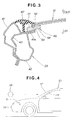
- FIG. 3 illustrates a windshield mounting structure according to a first embodiment of the present invention.
- the A-pillar 23 consists of an outer panel 41, an inner panel 42 disposed on the passenger compartment 36 side of the outer panel 41, and a reinforcing panel 43 mounted between the outer panel 41 and the inner panel 42.
- a resin hinge 46 is attached to a longitudinal end portion 41a of the outer panel 41.
- the resin hinge 46 is made from frangible material.
- the windshield 12 is mounted on the resin hinge 46.
- a windshield molding 47 covers an end of the windshield 12.
- the resin hinge 46 has a first notch 52 formed in a first surface 51 on which to mount the windshield 12 and a second notch 54 formed in a second surface 53 opposite to the first surface 51.
- the first notch 52 and the second notch 54 facilitate the deformation of the resin hinge 46.
- polypropylene (PP) a resin having high toughness and excellent flexing-fatigue resistance, is suitable.
- the windshield 12 is also mounted via a resin hinge 46.
- the present invention is first characterized in that the windshield mounting structure of the vehicle 10 for mounting the windshield 12 at the front of the passenger compartment 36 has the resin hinges 46 made from frangible material provided at the left and right A-pillars 23 and 24 as mounting members for the windshield 12, which hinges 46 are deformed when an external force larger than a given force acts on the windshield 12 from the outside of the passenger compartment 36, that is, the object 38 collides with the windshield 12 from the outside of the passenger compartment 36, so that the windshield 12 is moved in its entirety or in part inward into the passenger compartment 36.
- the resin hinges 46 can thus be deformed, causing the windshield 12 to move in its entirety or in part inward into the passenger compartment 36, further absorbing the impact in collision as compared with conventional windshield mounting structures, thereby mitigating impact force received by the collision object 38.
- the present invention is secondly characterized in that the resin hinges 46 are constituted by resin members each having the first notch 52 and the second notch 54.
- Providing notches to resin members to be the resin hinges 46 can facilitate the formation of the resign hinges 46 of frangible members, resulting in reduction in cost increase.
- the use of a material having high toughness, e.g., polypropylene for the resin members can allow the windshield 12 to be moved inward into the passenger compartment 36 without braking the resin hinges 46 and to be retained on the A-pillars 23 and 24.
- FIGS. 6A and 6B illustrate a windshield mounting structure according to a second embodiment.
- a resin support member 57 is bonded with an adhesive 56 to a longitudinal end portion 41a of an outer panel 41 of an A-pillar 23.
- the resin support member 57 constitutes a frangible member.
- An outer surface 58 of a windshield 12 is supported by the resin support member 57.
- a rubber connecting member 62 is fixed at its one end between the end portion 41a of the outer panel 41 and the resin support member 57 via the adhesive 56 and an adhesive 61.
- An inner surface 66 of the windshield 12 is bonded to the other end of the connecting member 62 via an adhesive 63.
- the resin support member 57 and the outer surface 58 of the windshield 12 are bonded together with an adhesive 67.
- the resin support member 57 has a notch 72 in an outer surface 71 on one side.
- the notch 72 facilitates the breakage of the resin support member 57.
- the windshield 12 receives an impact force, and the impact force causes the resin support member 57 to break from the notch 72. As a result, the windshield 12 largely moves toward the passenger compartment 36, mitigating the impact in collision. At that time, the connecting member 62 connects the A-pillar 23 and the windshield 12, preventing the windshield 12 from falling off.
- FIGS. 7A and 7B illustrate a windshield mounting structure according to a third embodiment.
- a support plate 75 as a frangible member is bonded at its one end with an adhesive 74 to an end portion 41a of an outer panel 41 of an A-pillar 23.
- the support plate 75 functions as an energy absorbing member for absorbing impact energy when a collision object collides with a windshield 12.
- the windshield 12 is bonded to the other end of the support plate 75 with an adhesive 76.
- the support plate 75 is a steel plate member consisting of a pillar mounting portion 81 to be attached to the A-pillar 23, a slant portion 82 extending at an angle from the pillar mounting portion 81 toward the windshield 12, and a windshield mounting portion 83 to which the windshield 12 is attached, extending from the front end of the slant portion 82 in parallel with the pillar mounting portion 81.
- the impact force acting on the windshield 12 causes the slant portion 82 of the support plate 75 to flex largely toward the passenger compartment 36, that is, to deform, and the windshield 12 largely moves inward into the passenger compartment 36.
- the support plate 75 absorbs impact energy acting on the windshield 12, mitigating the impact.
- a member of a honeycomb structure or a bellows structure may be interposed as an energy absorbing member between the A-pillar 23 and an end of the windshield 12.
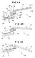
- FIGS. 8A to 8C illustrate a windshield mounting structure according to a fourth embodiment.
- a support plate 85 as a frangible member is attached at its one end with an adhesive 74 to an end portion 41a of an outer panel 41 of an A-pillar 23.
- a support base 86 is fixed to an end portion of the outer panel 41 in such a manner as straddling the support plate 85.
- a resin support member 87 as a frangible member is attached to the support base 86.
- To the resin support member 87, the other end of the support plate 85 is attached with an adhesive 88.
- a windshield 12 is mounted to the resin support member 87.
- the support plate 85 is a steel plate member consisting of a pillar mounting portion 91 to be attached to the A-pillar 23, a support member mounting portion 92 to be attached to the resin support member 87, and a connecting portion 93 for connecting the pillar mounting portion 91 and the support member mounting portion 92.
- the resin support member 87 has a first notch 96 provided in a first-side surface 94 and a second notch 98 provided in a second-side surface 97.
- the second-side surface 97 is attached on its one side with the second notch 98 as a border to the support base 86, and is attached the support plate 85 on the other side.
- the resin support member 87 and the support plate 85 can cause the windshield 12 to move in two stages inward into the passenger compartment 36, allowing a greater amount of movement of the windshield 12, and further absorbing impact energy.
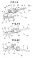
- FIGS. 9A to 9C illustrate a windshield mounting structure according to a fifth embodiment.
- a support plate 101 of a frangible member is bonded at its one end with an adhesive 74 to an end portion 41a of an outer panel 41 of an A-pillar 23.
- a resin support member 102 as a frangible member is attached with an adhesive 76.
- An outer surface 58 of a windshield 12 is attached to the resin support member 102 with an adhesive 67.
- a rubber connecting member 104 is attached at its one end with an adhesive 103. The other end of the connecting member 104 is attached to an inner surface 66 of the windshield 12 with an adhesive 63.
- the support plate 101 is, like the support plate 75 in the third embodiment shown in FIG. 7A, a steel plate member consisting of a pillar mounting portion 106, a slant portion 107, and a windshield mounting portion 108.
- the resin support member 102 has a notch 112 formed in a first-side surface 111.
- the connecting member 104 connects the A-pillar 23 and the windshield 12, preventing the windshield 12 from falling off.
- the support plate 101 and the resin support member 102 cause the windshield 12 to move in two stages inward into the passenger compartment 36, allowing a greater amount of movement of the windshield 12, and resulting in further absorption of impact energy.
- frangible members of the resin support members 46, 57, 87 and 102, and frangible members of the support plates 75, 85 and 101 are separately provided to the A-pillars 23 as mounting members of the windshields 12, but the present invention is not limited thereto.
- a frangible member may be provided integrally to a mounting member of the windshield 12 or directly integrally to the windshield 12.
- the resign hinge 46 is provided with both the first notch 52 and the second notch 54, which is not limiting. Only one of the first notch 52 and the second notch 54 may be provided.
- a windshield mounting structure includes A-pillars (23, 24) for mounting a windshield (12) and frangible members (46, 57, 75, 85, 87, 101, 102) provided at the A-pillars for supporting the windshield.
- frangible members When an object (38) collides with the windshield from the vehicle outside, the frangible members deform or break, thereby causing the windshield to move in its entirety or in part inward into a passenger compartment (36), absorbing the impact in collision.
Landscapes
- Engineering & Computer Science (AREA)
- Mechanical Engineering (AREA)
- Body Structure For Vehicles (AREA)
Abstract
Description
- The present invention relates to a vehicle windshield mounting structure for mitigating impact on collision objects when the collision objects collide with windshields from the front of vehicles.
- As this kind of windshield, a laminated safety glass consisting of an annealing glass, a resin interlayer bonded to the interior-side surface of the annealing glass and an impermeable film bonded to the interior-side surface of the resin interlayer is known as disclosed, for example, in Japanese Patent Laid-Open Publication No. HEI-4-19136.
- As another example of such a windshield, a windshield shown in FIGS. 10A and 10B is known. These figures illustrate a state in which a collision object is colliding with a windshield from the interior of a passenger compartment. In the figures, OUT indicates the outside of the passenger compartment and IN the inside of the passenger compartment.
- FIG. 10A illustrates a state in which a
collision object 211 is heading toward awindshield 212. Thewindshield 212 is made from a glass having twoglasses - The laminated safety glass in HEI-4-19136 or the
windshield 212 shown in FIG. 10A takes into account the safety of vehicle passengers, and mitigates impact on the head of a passenger hitting against the laminated safety glass or thewindshield 212 upon a vehicle collision. However, no consideration is given to the safety of pedestrians, that is, a collision object from the outside of the vehicle compartment toward the laminated safety glass or thewindshield 212. - In FIG. 10B, when the
collision object 211 hits on thewindshield 212, thewindshield 212 is partly broken, mitigating the impact of collision. However, as described above, thewindshield 212 does not allow for impact from the vehicle outside. Further, thewindshield 212 has a shape curved outward of the passenger compartment, that is, a so-called "arch" shape in cross section, and is thus more unbreakable against a load from the outside of the passenger compartment than from the inside of the passenger compartment. - Further, recent years' trends toward short-nose vehicles with passenger compartments expanded in space and slant-nose vehicles with front end portions inclined downward to reduce air resistance in high-speed travel result in increased collisions from the vehicle front toward windshields. On the other hand, under an increased rate of seatbelt wearing and the widespread adoption of airbags, importance is being attached to consideration to the safety of pedestrians in addition to the safety of vehicle passengers. In other words, it is desired to improve a vehicle windshield mounting structure so as to effectively mitigate the impact of collision with windshields from the outside of passenger compartments.
- According to the present invention, there is provided a vehicle windshield mounting structure, which comprises: a windshield; mounting members for mounting the windshield; and frangible members provided at the mounting members for supporting the windshield; the frangible members being configured to deform or break when an external force greater than a given force acts on the windshield from the outside of a passenger compartment, thereby causing the windshield to move in its entirety or in part inward into the passenger compartment.
- When an external force greater than a given force acts on the windshield from the outside of the passenger compartment, the frangible members deform or brake, so that the windshield can move in its entirety or in part inward into the passenger compartment, further absorbing impact in collision than in conventional windshield mounting structures, and mitigating impact received by a collision object.
- In this invention, the frangible members preferably comprise resin members each having at least one notch. Thus providing notches to resin members to be the frangible members can facilitate the formation of the frangible members, resulting in reduction in cost increase.
- Further, the use of a material having high toughness for the resin members can allow the windshield to be moved inward into the passenger compartment without breaking the resin members, and to be prevented from falling off the mounting members for retainment.
- Preferred embodiments of the present invention will be described in detail below, by way of example only, with reference to the accompanying drawings, in which:
- FIG. 1 is a perspective view of a front portion of a vehicle employing a windshield mounting structure according to the present invention;
- FIG. 2 is a cross-sectional view according to a first embodiment, taken along line 2-2 in FIG. 1;
- FIG. 3 is an enlarged cross-sectional view illustrating a portion of the windshield mounting structure according to the first embodiment shown in FIG. 2;
- FIG. 4 is a diagram illustrating a state in which a collision object is colliding with a windshield from the front of the vehicle;
- FIG. 5 is a diagram illustrating a state in which the collision object collides with the windshield, deforming a frangible member;
- FIGS. 6A and 6B are cross-sectional views illustrating a windshield mounting structure according to a second embodiment of the present invention;
- FIGS. 7A and 7B are cross-sectional views illustrating a windshield mounting structure according to a third embodiment of the present invention;
- FIGS. 8A to 8C are cross-sectional views illustrating a windshield mounting structure according to a fourth embodiment of the present invention;
- FIGS. 9A to 9C are cross-sectional views illustrating a windshield mounting structure according to a fifth embodiment of the present invention; and
- FIGS. 10A and 10B are cross-sectional views of the conventional windshield.
-
- Referring initially to FIG. 1, a
vehicle 10 has awindshield 12 at the front of a passenger compartment.Reference numeral 15 denotes a hood covering an upper portion of an engine compartment, 16 and 17 left and right front fenders, 18 a front bumper, 21 a front wheel (a front wheel on the other side is not shown), 23 and 24 left and right A-pillars, 25 a front door, and 26 a door mirror. - FIG. 2 illustrates a state in which the
windshield 12 is mounted between the left and right A-pillars 23 and 24. - The
windshield 12 is a laminated glass consisting of anouter glass 32 arranged outside of the vehicle, aninner glass 33 arranged inside of apassenger compartment 36, and aninterlayer 34 interposed between theouter glass 32 and theinner glass 33, bonding theouter glass 32 and theinner glass 33 together. As will be described below, when an external force greater than an external force of a given magnitude acts on thewindshield 12 from the outside of thepassenger compartment 36, stress is concentrated in the vicinities of the A-pillars 23 and 24 as mounting members of thewindshield 12, causing cracks in thewindshield 12, and thereby causing thewindshield 12 to move in its entirety or in part inward into thepassenger compartment 36, so that if an object collides from the outside of thepassenger compartment 36, the impact of collision is effectively mitigated. - FIG. 3 illustrates a windshield mounting structure according to a first embodiment of the present invention. The A-pillar 23 consists of an
outer panel 41, aninner panel 42 disposed on thepassenger compartment 36 side of theouter panel 41, and a reinforcingpanel 43 mounted between theouter panel 41 and theinner panel 42. Aresin hinge 46 is attached to alongitudinal end portion 41a of theouter panel 41. Theresin hinge 46 is made from frangible material. Thewindshield 12 is mounted on theresin hinge 46. Awindshield molding 47 covers an end of thewindshield 12. - The
resin hinge 46 has afirst notch 52 formed in afirst surface 51 on which to mount thewindshield 12 and asecond notch 54 formed in asecond surface 53 opposite to thefirst surface 51. Thefirst notch 52 and thesecond notch 54 facilitate the deformation of theresin hinge 46. For the material of theresin hinge 46, polypropylene (PP), a resin having high toughness and excellent flexing-fatigue resistance, is suitable. - To the
A-pillar 24 shown in FIG. 2, thewindshield 12 is also mounted via aresin hinge 46. - Now the function of the windshield mounting structure according to the above-described first embodiment will be described with reference to FIGS. 4 and 5.
- When a
collision object 38 heads toward thewindshield 12 from the front of thevehicle 10 as shown by an arrow in FIG. 4, and thecollision object 38 collides with thewindshield 12 as shown in FIG. 5, for example, theresin hinge 46 starts bending at thefirst notch 52 and thesecond notch 54. Thewindshield 12 then flexes largely inward into thepassenger compartment 36, absorbing the impact in collision. - Since the
resin hinges 46 are not broken, thewindshield 12 after collision can be retained on theresin hinges 46, having no possibility of falling off. - As described above with FIGS. 1, 3 and 5, the present invention is first characterized in that the windshield mounting structure of the
vehicle 10 for mounting thewindshield 12 at the front of thepassenger compartment 36 has theresin hinges 46 made from frangible material provided at the left and right A-pillars 23 and 24 as mounting members for thewindshield 12, whichhinges 46 are deformed when an external force larger than a given force acts on thewindshield 12 from the outside of thepassenger compartment 36, that is, theobject 38 collides with thewindshield 12 from the outside of thepassenger compartment 36, so that thewindshield 12 is moved in its entirety or in part inward into thepassenger compartment 36. - When an external force larger than a given force acts on the
windshield 12 from the outside of thepassenger compartment 36, theresin hinges 46 can thus be deformed, causing thewindshield 12 to move in its entirety or in part inward into thepassenger compartment 36, further absorbing the impact in collision as compared with conventional windshield mounting structures, thereby mitigating impact force received by thecollision object 38. - The present invention is secondly characterized in that the
resin hinges 46 are constituted by resin members each having thefirst notch 52 and thesecond notch 54. - Providing notches to resin members to be the
resin hinges 46 can facilitate the formation of theresign hinges 46 of frangible members, resulting in reduction in cost increase. - The use of a material having high toughness, e.g., polypropylene for the resin members can allow the
windshield 12 to be moved inward into thepassenger compartment 36 without braking theresin hinges 46 and to be retained on the A-pillars 23 and 24. - FIGS. 6A and 6B illustrate a windshield mounting structure according to a second embodiment.
- As shown in FIG. 6A, a
resin support member 57 is bonded with an adhesive 56 to alongitudinal end portion 41a of anouter panel 41 of an A-pillar 23. Theresin support member 57 constitutes a frangible member. Anouter surface 58 of awindshield 12 is supported by theresin support member 57. Arubber connecting member 62 is fixed at its one end between theend portion 41a of theouter panel 41 and theresin support member 57 via the adhesive 56 and an adhesive 61. Aninner surface 66 of thewindshield 12 is bonded to the other end of the connectingmember 62 via an adhesive 63. Theresin support member 57 and theouter surface 58 of thewindshield 12 are bonded together with an adhesive 67. - The
resin support member 57 has anotch 72 in anouter surface 71 on one side. Thenotch 72 facilitates the breakage of theresin support member 57. - As shown in FIG. 6B, when a collision object collides with the
windshield 12 from the outside of apassenger compartment 36, thewindshield 12 receives an impact force, and the impact force causes theresin support member 57 to break from thenotch 72. As a result, thewindshield 12 largely moves toward thepassenger compartment 36, mitigating the impact in collision. At that time, the connectingmember 62 connects the A-pillar 23 and thewindshield 12, preventing thewindshield 12 from falling off. - FIGS. 7A and 7B illustrate a windshield mounting structure according to a third embodiment.
- As shown in FIG. 7A, a
support plate 75 as a frangible member is bonded at its one end with an adhesive 74 to anend portion 41a of anouter panel 41 of an A-pillar 23. Thesupport plate 75 functions as an energy absorbing member for absorbing impact energy when a collision object collides with awindshield 12. Thewindshield 12 is bonded to the other end of thesupport plate 75 with an adhesive 76. - The
support plate 75 is a steel plate member consisting of apillar mounting portion 81 to be attached to the A-pillar 23, aslant portion 82 extending at an angle from thepillar mounting portion 81 toward thewindshield 12, and awindshield mounting portion 83 to which thewindshield 12 is attached, extending from the front end of theslant portion 82 in parallel with thepillar mounting portion 81. - As shown in FIG. 7B, when a collision object collides with the
windshield 12 from the outside of apassenger compartment 36, the impact force acting on thewindshield 12 causes theslant portion 82 of thesupport plate 75 to flex largely toward thepassenger compartment 36, that is, to deform, and thewindshield 12 largely moves inward into thepassenger compartment 36. As a result, thesupport plate 75 absorbs impact energy acting on thewindshield 12, mitigating the impact. - In place of the
support plate 75, a member of a honeycomb structure or a bellows structure may be interposed as an energy absorbing member between the A-pillar 23 and an end of thewindshield 12. - FIGS. 8A to 8C illustrate a windshield mounting structure according to a fourth embodiment.
- As shown in FIG. 8A, a
support plate 85 as a frangible member is attached at its one end with an adhesive 74 to anend portion 41a of anouter panel 41 of an A-pillar 23. Asupport base 86 is fixed to an end portion of theouter panel 41 in such a manner as straddling thesupport plate 85. Aresin support member 87 as a frangible member is attached to thesupport base 86. To theresin support member 87, the other end of thesupport plate 85 is attached with an adhesive 88. Awindshield 12 is mounted to theresin support member 87. - The
support plate 85 is a steel plate member consisting of apillar mounting portion 91 to be attached to the A-pillar 23, a support member mounting portion 92 to be attached to theresin support member 87, and a connectingportion 93 for connecting thepillar mounting portion 91 and the support member mounting portion 92. - The
resin support member 87 has afirst notch 96 provided in a first-side surface 94 and asecond notch 98 provided in a second-side surface 97. The second-side surface 97 is attached on its one side with thesecond notch 98 as a border to thesupport base 86, and is attached thesupport plate 85 on the other side. - In FIG. 8B, when an object collides with the
windshield 12 from the outside of apassenger compartment 36, the impact force acting on thewindshield 12 causes theresin support member 87 to start breaking at thefirst notch 96 and thesecond notch 98, and thewindshield 12 moves inward into thepassenger compartment 36. - In FIG. 8C, after the
resin support member 87 breaks, the connectingportion 93 of thesupport plate 85 largely flexes, causing thewindshield 12 to move largely inward into thepassenger compartment 36. As a result, thesupport plate 85 absorbs impact energy acting on thewindshield 12, mitigating the impact in collision. - In the fourth embodiment, the
resin support member 87 and thesupport plate 85 can cause thewindshield 12 to move in two stages inward into thepassenger compartment 36, allowing a greater amount of movement of thewindshield 12, and further absorbing impact energy. - FIGS. 9A to 9C illustrate a windshield mounting structure according to a fifth embodiment.
- As shown in FIG. 9A, a
support plate 101 of a frangible member is bonded at its one end with an adhesive 74 to anend portion 41a of anouter panel 41 of an A-pillar 23. To the other end of thesupport plate 101, aresin support member 102 as a frangible member is attached with an adhesive 76. Anouter surface 58 of awindshield 12 is attached to theresin support member 102 with an adhesive 67. To the other end of thesupport plate 102, arubber connecting member 104 is attached at its one end with an adhesive 103. The other end of the connectingmember 104 is attached to aninner surface 66 of thewindshield 12 with an adhesive 63. - The
support plate 101 is, like thesupport plate 75 in the third embodiment shown in FIG. 7A, a steel plate member consisting of apillar mounting portion 106, aslant portion 107, and awindshield mounting portion 108. Theresin support member 102 has anotch 112 formed in a first-side surface 111. - In FIG. 9B, when an object collides with the
windshield 12 from the outside of apassenger compartment 36, the impact force acting on thewindshield 12 causes theslant portion 107 of thesupport plate 107 to largely flex, and thewindshield 12 largely moves inward into thepassenger compartment 36. - When the other end of the
support plate 101 or specifically the one end of the connectingmember 104 attached to thesupport plate 101 abuts on theend portion 41a of theouter panel 41 of the A-pillar 23, impact force acts on theresin support member 102 as shown in FIG. 9C, and theresin support member 102 starts breaking at thenotch 112, so that thewindshield 12 further moves inward into thepassenger compartment 36, absorbing impact energy acting on thewindshield 12, and mitigating the impact in collision. - At that time, the connecting
member 104 connects the A-pillar 23 and thewindshield 12, preventing thewindshield 12 from falling off. - In the fifth embodiment, as in the fourth embodiment shown in FIG. 8A, the
support plate 101 and theresin support member 102 cause thewindshield 12 to move in two stages inward into thepassenger compartment 36, allowing a greater amount of movement of thewindshield 12, and resulting in further absorption of impact energy. - In the above-described embodiments, frangible members of the
resin support members support plates windshields 12, but the present invention is not limited thereto. A frangible member may be provided integrally to a mounting member of thewindshield 12 or directly integrally to thewindshield 12. - In the first embodiment shown in FIG. 3, the resign
hinge 46 is provided with both thefirst notch 52 and thesecond notch 54, which is not limiting. Only one of thefirst notch 52 and thesecond notch 54 may be provided. - A windshield mounting structure includes A-pillars (23, 24) for mounting a windshield (12) and frangible members (46, 57, 75, 85, 87, 101, 102) provided at the A-pillars for supporting the windshield. When an object (38) collides with the windshield from the vehicle outside, the frangible members deform or break, thereby causing the windshield to move in its entirety or in part inward into a passenger compartment (36), absorbing the impact in collision.
Claims (2)
- A vehicle windshield mounting structure, comprising:a windshield (12);mounting members (23, 24) for mounting said windshield; andfrangible members (46, 57, 75, 85, 87, 101, 102) provided at said mounting members for supporting said windshield;said frangible members being configured to deform or break when an external force greater than a given force acts on said windshield from the outside of a passenger compartment (36), thereby causing said windshield to move in its entirety or in part inward into said passenger compartment.
- The vehicle windshield mounting structure of claim 1, wherein said frangible members comprise resin members each having at least one notch (52, 54, 72, 96, 98, 112).
Applications Claiming Priority (2)
| Application Number | Priority Date | Filing Date | Title |
|---|---|---|---|
| JP2002169178A JP2004009965A (en) | 2002-06-10 | 2002-06-10 | Vehicle windshield mounting structure |
| JP2002169178 | 2002-06-10 |
Publications (2)
| Publication Number | Publication Date |
|---|---|
| EP1371510A1 true EP1371510A1 (en) | 2003-12-17 |
| EP1371510B1 EP1371510B1 (en) | 2010-05-12 |
Family
ID=29561733
Family Applications (1)
| Application Number | Title | Priority Date | Filing Date |
|---|---|---|---|
| EP03012935A Expired - Lifetime EP1371510B1 (en) | 2002-06-10 | 2003-06-06 | Vehicle windshield mounting structure |
Country Status (4)
| Country | Link |
|---|---|
| US (1) | US6769730B2 (en) |
| EP (1) | EP1371510B1 (en) |
| JP (1) | JP2004009965A (en) |
| DE (1) | DE60332512D1 (en) |
Cited By (3)
| Publication number | Priority date | Publication date | Assignee | Title |
|---|---|---|---|---|
| EP1808364A1 (en) * | 2006-01-16 | 2007-07-18 | Ford Global Technologies, LLC | Vehicle front interior structure |
| EP1810893A1 (en) * | 2006-01-16 | 2007-07-25 | Ford Global Technologies, LLC | Vehicle front interior structure |
| EP1810892A1 (en) * | 2006-01-16 | 2007-07-25 | Ford Global Technologies, LLC | Vehicle front interior structure |
Families Citing this family (8)
| Publication number | Priority date | Publication date | Assignee | Title |
|---|---|---|---|---|
| US8136870B2 (en) | 2009-09-23 | 2012-03-20 | Toyota Motor Engineering & Manufacturing North America, Inc. | Cowl braces and windshield support assemblies with cowl braces |
| DE102010054718A1 (en) | 2010-12-16 | 2012-07-05 | GM Global Technology Operations LLC | Retention device for use in motor to receive shock during collision, has disk and/or plate-like body deformed during collision such that body is disconnected from frame of motor car during collision |
| DE102011111237A1 (en) * | 2011-08-20 | 2013-02-21 | GM Global Technology Operations LLC (n. d. Gesetzen des Staates Delaware) | Automotive body |
| US9610981B1 (en) | 2016-01-12 | 2017-04-04 | Honda Motor Co., Ltd. | Vehicle body assembly |
| EP3666641B1 (en) * | 2018-12-11 | 2021-05-05 | AIRBUS HELICOPTERS DEUTSCHLAND GmbH | Foreign object impact proof windshield assembly |
| US11180003B2 (en) * | 2020-02-06 | 2021-11-23 | Fca Us Llc | Support for a vehicle window |
| US11345409B1 (en) | 2020-12-18 | 2022-05-31 | Ford Global Technologies, Llc | Canopy windshield retention |
| FR3163637A1 (en) * | 2024-06-24 | 2025-12-26 | Airbus Helicopters | Aircraft equipped with a transparent wall attached to a structure by a shock-absorbing system |
Citations (4)
| Publication number | Priority date | Publication date | Assignee | Title |
|---|---|---|---|---|
| US3764178A (en) * | 1970-10-29 | 1973-10-09 | Saint Gobain | Safety windshield |
| US3843193A (en) * | 1971-07-28 | 1974-10-22 | Saint Gobain | Windshield mounting |
| US5419088A (en) * | 1992-11-09 | 1995-05-30 | Rohm And Haas Company | Energy absorbing mounting systems for motor vehicles windows |
| US5422058A (en) * | 1993-03-03 | 1995-06-06 | Okamoto; Satoru | Mounting structure of sheet glass on window frame and the like |
Family Cites Families (3)
| Publication number | Priority date | Publication date | Assignee | Title |
|---|---|---|---|---|
| JPH0419136A (en) | 1990-05-14 | 1992-01-23 | Nippon Sheet Glass Co Ltd | Safety laminated glass |
| JP3449463B2 (en) * | 1998-05-12 | 2003-09-22 | 本田技研工業株式会社 | Windshield support structure |
| JP3939861B2 (en) * | 1998-07-24 | 2007-07-04 | 本田技研工業株式会社 | Windshield support structure |
-
2002
- 2002-06-10 JP JP2002169178A patent/JP2004009965A/en active Pending
-
2003
- 2003-05-30 US US10/449,164 patent/US6769730B2/en not_active Expired - Fee Related
- 2003-06-06 DE DE60332512T patent/DE60332512D1/en not_active Expired - Lifetime
- 2003-06-06 EP EP03012935A patent/EP1371510B1/en not_active Expired - Lifetime
Patent Citations (4)
| Publication number | Priority date | Publication date | Assignee | Title |
|---|---|---|---|---|
| US3764178A (en) * | 1970-10-29 | 1973-10-09 | Saint Gobain | Safety windshield |
| US3843193A (en) * | 1971-07-28 | 1974-10-22 | Saint Gobain | Windshield mounting |
| US5419088A (en) * | 1992-11-09 | 1995-05-30 | Rohm And Haas Company | Energy absorbing mounting systems for motor vehicles windows |
| US5422058A (en) * | 1993-03-03 | 1995-06-06 | Okamoto; Satoru | Mounting structure of sheet glass on window frame and the like |
Cited By (3)
| Publication number | Priority date | Publication date | Assignee | Title |
|---|---|---|---|---|
| EP1808364A1 (en) * | 2006-01-16 | 2007-07-18 | Ford Global Technologies, LLC | Vehicle front interior structure |
| EP1810893A1 (en) * | 2006-01-16 | 2007-07-25 | Ford Global Technologies, LLC | Vehicle front interior structure |
| EP1810892A1 (en) * | 2006-01-16 | 2007-07-25 | Ford Global Technologies, LLC | Vehicle front interior structure |
Also Published As
| Publication number | Publication date |
|---|---|
| US20030227191A1 (en) | 2003-12-11 |
| JP2004009965A (en) | 2004-01-15 |
| DE60332512D1 (en) | 2010-06-24 |
| EP1371510B1 (en) | 2010-05-12 |
| US6769730B2 (en) | 2004-08-03 |
Similar Documents
| Publication | Publication Date | Title |
|---|---|---|
| CN1131801C (en) | Safety bumper comprising an energy-absorbing element controlled by an impact sensor | |
| KR101097018B1 (en) | Automotive doors with enhanced side impact performance | |
| US6851737B2 (en) | Vehicle windshield mounting structure | |
| US6769730B2 (en) | Vehicle windshield mounting structure | |
| US6840659B2 (en) | Transition region between a vehicle engine hood or front trunk lid and a headlight | |
| JP3100296U (en) | Structure for front part of vehicle that can control deformation for pedestrian safety protection | |
| US20030098192A1 (en) | Large vehicle hood or trunk lid bodyshell element | |
| JP2002284035A (en) | Upper front pillar structure of a car | |
| CA2449904A1 (en) | Rail vehicle, in particular lightweight motor car | |
| JP2000289550A (en) | Automotive impact absorbing device | |
| KR200146703Y1 (en) | Car door structure | |
| JPH11255149A (en) | Vehicle roof side rail | |
| KR100334276B1 (en) | Structure for assembling shroud panel | |
| JP2006205779A (en) | Vehicle door structure | |
| KR100394706B1 (en) | Structure for reinforcing a rear bumper for automobiles | |
| KR200149041Y1 (en) | Door impact beam with impct absorption material for a car | |
| KR100338508B1 (en) | An Double Shot Gun Structure in Vehicle | |
| KR0139596Y1 (en) | Rear shock absorber structure of automobile | |
| JP2001151147A (en) | Car front pillar | |
| JP2001163256A (en) | Car front pillar | |
| JP2002029448A (en) | Impact energy absorbing structure | |
| KR20030096501A (en) | Impact absorbing structure of pilar trim for car | |
| JPH03121923A (en) | Door construction for vehicle | |
| JP2007168584A (en) | Hood airbag device for vehicle | |
| KR20010063553A (en) | Fender panel structure for preventing pedestrain |
Legal Events
| Date | Code | Title | Description |
|---|---|---|---|
| PUAI | Public reference made under article 153(3) epc to a published international application that has entered the european phase |
Free format text: ORIGINAL CODE: 0009012 |
|
| AK | Designated contracting states |
Kind code of ref document: A1 Designated state(s): AT BE BG CH CY CZ DE DK EE ES FI FR GB GR HU IE IT LI LU MC NL PT RO SE SI SK TR |
|
| AX | Request for extension of the european patent |
Extension state: AL LT LV MK |
|
| 17P | Request for examination filed |
Effective date: 20040225 |
|
| 17Q | First examination report despatched |
Effective date: 20040330 |
|
| AKX | Designation fees paid |
Designated state(s): DE FR GB |
|
| GRAP | Despatch of communication of intention to grant a patent |
Free format text: ORIGINAL CODE: EPIDOSNIGR1 |
|
| GRAS | Grant fee paid |
Free format text: ORIGINAL CODE: EPIDOSNIGR3 |
|
| GRAA | (expected) grant |
Free format text: ORIGINAL CODE: 0009210 |
|
| AK | Designated contracting states |
Kind code of ref document: B1 Designated state(s): DE FR GB |
|
| REG | Reference to a national code |
Ref country code: GB Ref legal event code: FG4D |
|
| REF | Corresponds to: |
Ref document number: 60332512 Country of ref document: DE Date of ref document: 20100624 Kind code of ref document: P |
|
| PGFP | Annual fee paid to national office [announced via postgrant information from national office to epo] |
Ref country code: FR Payment date: 20100709 Year of fee payment: 8 |
|
| PGFP | Annual fee paid to national office [announced via postgrant information from national office to epo] |
Ref country code: DE Payment date: 20100602 Year of fee payment: 8 Ref country code: GB Payment date: 20100602 Year of fee payment: 8 |
|
| PLBE | No opposition filed within time limit |
Free format text: ORIGINAL CODE: 0009261 |
|
| STAA | Information on the status of an ep patent application or granted ep patent |
Free format text: STATUS: NO OPPOSITION FILED WITHIN TIME LIMIT |
|
| 26N | No opposition filed |
Effective date: 20110215 |
|
| REG | Reference to a national code |
Ref country code: DE Ref legal event code: R097 Ref document number: 60332512 Country of ref document: DE Effective date: 20110214 |
|
| GBPC | Gb: european patent ceased through non-payment of renewal fee |
Effective date: 20110606 |
|
| REG | Reference to a national code |
Ref country code: FR Ref legal event code: ST Effective date: 20120229 |
|
| REG | Reference to a national code |
Ref country code: DE Ref legal event code: R119 Ref document number: 60332512 Country of ref document: DE Effective date: 20120103 |
|
| PG25 | Lapsed in a contracting state [announced via postgrant information from national office to epo] |
Ref country code: FR Free format text: LAPSE BECAUSE OF NON-PAYMENT OF DUE FEES Effective date: 20110630 Ref country code: DE Free format text: LAPSE BECAUSE OF NON-PAYMENT OF DUE FEES Effective date: 20120103 |
|
| PG25 | Lapsed in a contracting state [announced via postgrant information from national office to epo] |
Ref country code: GB Free format text: LAPSE BECAUSE OF NON-PAYMENT OF DUE FEES Effective date: 20110606 |