EP1371347B1 - Grooved phaco-emulsification needle - Google Patents
Grooved phaco-emulsification needle Download PDFInfo
- Publication number
- EP1371347B1 EP1371347B1 EP03015611A EP03015611A EP1371347B1 EP 1371347 B1 EP1371347 B1 EP 1371347B1 EP 03015611 A EP03015611 A EP 03015611A EP 03015611 A EP03015611 A EP 03015611A EP 1371347 B1 EP1371347 B1 EP 1371347B1
- Authority
- EP
- European Patent Office
- Prior art keywords
- needle
- circumference
- phaco
- sleeve
- emulsification
- Prior art date
- Legal status (The legal status is an assumption and is not a legal conclusion. Google has not performed a legal analysis and makes no representation as to the accuracy of the status listed.)
- Expired - Lifetime
Links
Images


Classifications
-
- A—HUMAN NECESSITIES
- A61—MEDICAL OR VETERINARY SCIENCE; HYGIENE
- A61F—FILTERS IMPLANTABLE INTO BLOOD VESSELS; PROSTHESES; DEVICES PROVIDING PATENCY TO, OR PREVENTING COLLAPSING OF, TUBULAR STRUCTURES OF THE BODY, e.g. STENTS; ORTHOPAEDIC, NURSING OR CONTRACEPTIVE DEVICES; FOMENTATION; TREATMENT OR PROTECTION OF EYES OR EARS; BANDAGES, DRESSINGS OR ABSORBENT PADS; FIRST-AID KITS
- A61F9/00—Methods or devices for treatment of the eyes; Devices for putting-in contact lenses; Devices to correct squinting; Apparatus to guide the blind; Protective devices for the eyes, carried on the body or in the hand
- A61F9/007—Methods or devices for eye surgery
- A61F9/00736—Instruments for removal of intra-ocular material or intra-ocular injection, e.g. cataract instruments
- A61F9/00745—Instruments for removal of intra-ocular material or intra-ocular injection, e.g. cataract instruments using mechanical vibrations, e.g. ultrasonic
-
- A—HUMAN NECESSITIES
- A61—MEDICAL OR VETERINARY SCIENCE; HYGIENE
- A61B—DIAGNOSIS; SURGERY; IDENTIFICATION
- A61B17/00—Surgical instruments, devices or methods, e.g. tourniquets
- A61B17/32—Surgical cutting instruments
- A61B17/320068—Surgical cutting instruments using mechanical vibrations, e.g. ultrasonic
- A61B2017/320072—Working tips with special features, e.g. extending parts
- A61B2017/320074—Working tips with special features, e.g. extending parts blade
- A61B2017/320075—Working tips with special features, e.g. extending parts blade single edge blade, e.g. for cutting
-
- A—HUMAN NECESSITIES
- A61—MEDICAL OR VETERINARY SCIENCE; HYGIENE
- A61B—DIAGNOSIS; SURGERY; IDENTIFICATION
- A61B17/00—Surgical instruments, devices or methods, e.g. tourniquets
- A61B17/32—Surgical cutting instruments
- A61B17/320068—Surgical cutting instruments using mechanical vibrations, e.g. ultrasonic
- A61B2017/320072—Working tips with special features, e.g. extending parts
- A61B2017/32008—Working tips with special features, e.g. extending parts preventing clogging of suction channel
-
- A—HUMAN NECESSITIES
- A61—MEDICAL OR VETERINARY SCIENCE; HYGIENE
- A61B—DIAGNOSIS; SURGERY; IDENTIFICATION
- A61B17/00—Surgical instruments, devices or methods, e.g. tourniquets
- A61B17/32—Surgical cutting instruments
- A61B17/320068—Surgical cutting instruments using mechanical vibrations, e.g. ultrasonic
- A61B2017/320084—Irrigation sleeves
-
- A—HUMAN NECESSITIES
- A61—MEDICAL OR VETERINARY SCIENCE; HYGIENE
- A61M—DEVICES FOR INTRODUCING MEDIA INTO, OR ONTO, THE BODY; DEVICES FOR TRANSDUCING BODY MEDIA OR FOR TAKING MEDIA FROM THE BODY; DEVICES FOR PRODUCING OR ENDING SLEEP OR STUPOR
- A61M1/00—Suction or pumping devices for medical purposes; Devices for carrying-off, for treatment of, or for carrying-over, body-liquids; Drainage systems
- A61M1/84—Drainage tubes; Aspiration tips
- A61M1/85—Drainage tubes; Aspiration tips with gas or fluid supply means, e.g. for supplying rinsing fluids or anticoagulants
Definitions
- the present invention relates generally to phaco-emulsification needles and more particularly to needles that provide improved irrigation and reduced risk of corneal or scleral tissue damage.
- cataracts in which the lens of the eye becomes clouded, is common, and can lead to blindness. It has become accepted practice to alleviate this condition by surgically removing the cataract-effected lens and replacing it by an artificial intraocular lens.
- the cataract-effected lens is usually removed by manual extraction or phaco-emulsification.
- Manual extraction requires expression of the nucleus of the lens through a wound of about 12 mm in length.
- phaco-emulsification enables removal of a cataract-effected lens through a much smaller incision of about 2.5-4 mm, for example, 3.2 mm. This is accomplished using high frequency ultrasound energy, typically of 40 kHz frequency, that is transmitted by a phaco-emulsification needle to fragment or emulsify the nucleus of the cataract-effected lens. Once fragmented or emulsified, the nuclear material is aspirated through a lumen of the phaco-emulsification needle.
- a simultaneous flow of liquid into the eye is provided around the needle via a soft plastic or elastomeric sleeve concentrically disposed over the needle to form an annulus.
- This flow of liquid into the eye is essential to prevent collapse of the anterior chamber of the eye while the fragmented or emulsified nucleus is aspirated via the phaco-emulsification needle.
- the inflowing liquid serves to cool the needle, thus reducing heat generated by the ultrasonic vibration of the needle. If this heat were instead permitted to be transmitted to the entry wound of the eye, thermal damage of the cornea or scleral tissue could result.
- One difficulty encountered in practicing the phaco-emulsification technique is the necessity of maintaining a low-leakage seal between the entry wound in the eye and the sleeve surrounding the phaco-emulsification needle. If the wound entrance is too small, the sleeve may be compressed against the needle, thereby restricting the flow of irrigant into the anterior chamber and allowing frictional heat to be transmitted to the wound.
- a first technique uses a rigid plastic sleeve made from a material such as polysulphone rather than a softer silicone material, because polysulphone resists compression by the wound.
- Another technique described in U.S. Patent 5,282,786 , incorporates a rigid plastic or metal sleeve disposed on the outer circumference of a softer silicone sleeve, so that the rigid plastic contacts the entry wound.
- a second technique employs a rigid plastic or metal intermediate sleeve inserted in the annulus between the conventional outer soft silicone sleeve and the phaco-emulsification needle.
- the rigid intermediate sleeve is permitted to "float" on the exterior of the phaco-emulsification needle, and the needle may have a reduced outer diameter in a middle region to limit longitudinal travel of the intermediate sleeve.
- the reduced middle region of the needle permits a small incision while maintaining fluid flow around the phaco-emulsification needle.
- such benefits are believed to be more than offset by the increase in the overall diameter of the apparatus to accommodate the intermediate sleeve and the overall reduction in the irrigation cross-sectional flow area caused by the presence of the intermediate sleeve.
- a phaco-emulsification needle that overcomes the drawbacks of previously known needle and sleeve arrangements by permitting the use of a small wound size, and that reduces the risk of restriction of fluid flow around the needle.
- a phaco-emulsification needle as described comprises a shaft having an axially extending lumen for removal of material from an eye, and at least in a middle region of the needle, one or more axially extending channels or grooves disposed externally of the lumen for supplying fluid to the eye during aspiration.
- the channels or grooves permit continued fluid flow while reducing the contact area between the sleeve and needle, thereby reducing the risk of thermal damage to the entry wound.
- a previously known phaco-emulsification needle 10 comprising hub 12 and hollow shaft 14 extending from hub 12.
- a threaded portion 16 extends away from hub 12 on the proximal portion of shaft 14, as is conventional.
- Shaft 14 terminates in tip 18 at the distal end (i.e., remote from hub 12).
- Needle 10 contains a central axially extending lumen 13 through which material can be drawn from an eye using known techniques, as described hereinabove.
- sleeve 17 can be compressed by the eye, and in particular, the portion surrounding the entry wound, to reduce liquid flow to an unacceptable extent.
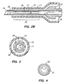
- Needle 20 which is typically made of titanium, comprises hub 12, lumen 13, threaded portion 16, tip 18 and tubular portion 21 located in mid-region 25 between tip 18 and hub 12.
- tubular portion 21 illustratively comprises hollow reduced-circumference cylindrical member 22 having a plurality of equispaced rib-like projections or flanges 24 extending radially outwardly from the outer surface of member 22.
- FIG. 2B if projections 24 in mid-region 25 are alternatively viewed from the perspective of the outer diameter of the adjacent proximal and distal regions, the interstices between adjacent projections 24 appear as longitudinally-oriented channels or grooves 30 in the outer surface of needle 20.
- Projections 24 on reduced-circumference cylindrical member 22 may have their outer surfaces formed flush with the outer surface of needle 20 in the regions proximal and distal to mid-region 25 (as in FIG. 2B ), or extend slightly below or beyond the outer surface of needle 20 in the adjacent proximal and distal regions.
- lumen 13 may have a reduced diameter in central region 25, as can be seen by comparison of FIGS. 3 and 4 .
- Projections 24 and reduced-circumference cylindrical member 22 may be disposed only in central or mid-region 25 of needle 20, which is the region typically subjected to compressive loading by the tissue surrounding the entry wound, or may alternatively extend along the entire outer surface of needle 20 to tip 18.
- sleeve 17 Disposed about and spaced from tubular portion 21 is sleeve 17, which may be formed of soft plastic or elastomeric material, for example, silicone.
- sleeve tube 17 When sleeve tube 17 is subjected to a compressive load and contacts needle 20, adjacent projections 24, together with the intervening portion of reduced-circumference cylindrical member 22 and the inner surface of sleeve 17, form channels or grooves 30 which extend axially along needle 20.
- Tubular portion 21 may be of a variety of shapes in cross-section, including circular and elliptical, and may have an outer circumference that is smaller than, the same as, or larger than the circumference of the adjacent proximal and distal portions of needle 20.
- central lumen 13 of needle 20 may have a single diameter over its entire length, or may be formed having a reduced diameter in the mid-region of tubular portion 21.
- projections 24 may be greater or fewer in number than shown in the accompanying figures, and form greater or lesser portions of the outer circumference of central portion 25 than shown in the accompanying figures, which are to be understood as exemplary only.
- projections 24 need not be spaced equidistant apart around the circumference of tubular portion 24, but may instead be concentrated on the upper and lower portions of needle 20, which are most likely to experience compressive loads.
- needle 20' has longitudinally-oriented projections 24 that spiral around the circumference of cylindrical member 22, thereby creating spiral channels.
- projections 24 may be formed or machined to create hollow channels 26 that communicate with lumen 13, thereby increasing the flow area through the mid-portion of the needle.
- the rib-like projections 24 of any of the embodiments of FIGS. 2-5 may advantageously include hollow channels 26.
- the channels may be disposed either in the mid-portion of the needle, or extend for the length of the entire inner surface of the needle.
- projections 24 on needle 20 are formed as individual longitudinally-oriented diamond-shaped islands extending outward from the outer circumference of cylindrical member 22, for example, by cross-cutting reverse-spiral grooves in the needle of FIG. 5 .
- grooves 30 may be disposed in a needles 20' and 20'' by rotating the needle as the grooves 30 are being formed.
- projections 24 and cylindrical member 22 may be formed by machining a single piece of titanium to the desired shape.
- a phaco-emulsification needle in accordance with the present invention may be formed from stainless steel, a suitably tough plastic composite, or a combination thereof.
- projections 24 may be formed in any of a number of readily manufacturable configurations, for example, as circumferential channels with longitudinally-oriented communications, or even cylindrical nub-like shapes.
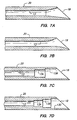
- FIGS. 7A through 7D alternative designs of tip 18 of needle 20 are illustrated.
- FIG. 7A shows lumen 13 in the distal portion of needle 20 expanding to tip 18 in a funnel-like manner;
- FIG. 7B shows the lumen 13 having a curved horn-like shape as it expands to tip 18.
- FIGS. 7C and 7D illustrate alternative embodiments in which lumen 13 expands to tip 18 through a series of multi-chamber steps 13A-13B and 13A-13C.
- the foregoing lumen and tip configurations may be advantageously used with any of the phaco-emulsification needles of the present invention.
- Needle 40 includes reduced-circumference portion 21 in mid-region 25. Flanges or projections 24 and cylindrical member 22 form a separate insert 41 which is disposed on the reduced-circumference portion 21 of needle 40.
- Insert 41 may be formed of a soft plastic or elastomeric material, for example, silicone, and preferably is dimensioned so that gap 42 forms between the inner surface of cylindrical member 22 and the outer surface of reduced-circumference portion 21.
- Cylindrical member 22 may also include a longitudinal slit that permits cylindrical member 22 to be easily installed over reduced-circumference portion 21.
- cylindrical member 22 may be dimensioned to slip over a standard phaco-emulsification needle 10 as shown in FIG. 1 , but may then require the use of a larger sleeve 17 and larger entry wound.
- insert 41 is expected to provide many of the advantages described hereinabove with respect to the needle embodiments of FIGS. 2-6 .
- Applicant has performed some closed chamber experiments employing a silicone model "eye” used in phaco-emulsification training workshops, in which the silicone "cornea” can be exchanged.
- applicant used a Series 10000 Master phaco-emulsification system, available from Alcon Surgical, Fort Worth, Texas, to compare the cooling performance of a needle constructed in accordance with the embodiment of FIG. 2 to a standard Master phaco-emulsification needle.
- the sleeve temperature was lower for the needle of FIG. 2 at all incision sizes and always remained below 40 °C. In contrast, using the standard tip, the sleeve reached temperature levels exceeding fifty degrees -- a temperature at which thermal damage and collagen shrinkage would be expected to occur.
- Applicant performed similar experiments in which the incision size was maintained at 3.00 mm and the flow rate was varied from 20 to 35 cc/min. While the performance of neither the standard needle nor the needle of FIG. 2 varied much with change in irrigant flow rate, the sleeve temperature for the needle of FIG. 2 was consistently about 20 °C lower than for the standard needle. In yet a third series of experiments, applicant kept the incision size at 3.00 mm and the flow rate constant at 20 cc/min and varied the irrigant bottle height from 65 to 75 cm. This also did not produce much an effect in the sleeve temperature for either needle, but again the sleeve temperature for the needle of FIG. 2 was consistently about 20 °C lower than for the standard needle.
Landscapes
- Health & Medical Sciences (AREA)
- Ophthalmology & Optometry (AREA)
- Life Sciences & Earth Sciences (AREA)
- Animal Behavior & Ethology (AREA)
- Engineering & Computer Science (AREA)
- Biomedical Technology (AREA)
- Heart & Thoracic Surgery (AREA)
- Vascular Medicine (AREA)
- Nuclear Medicine, Radiotherapy & Molecular Imaging (AREA)
- Surgery (AREA)
- General Health & Medical Sciences (AREA)
- Public Health (AREA)
- Veterinary Medicine (AREA)
- Surgical Instruments (AREA)
- Colloid Chemistry (AREA)
- Media Introduction/Drainage Providing Device (AREA)
- Medicinal Preparation (AREA)
Abstract
Description
- The present invention relates generally to phaco-emulsification needles and more particularly to needles that provide improved irrigation and reduced risk of corneal or scleral tissue damage.
- Occurrence of the disease known as cataracts, in which the lens of the eye becomes clouded, is common, and can lead to blindness. It has become accepted practice to alleviate this condition by surgically removing the cataract-effected lens and replacing it by an artificial intraocular lens.
- The cataract-effected lens is usually removed by manual extraction or phaco-emulsification. Manual extraction requires expression of the nucleus of the lens through a wound of about 12 mm in length.
- The technique known as phaco-emulsification, as described, for example, in
U.S. Patent 3,589,363 , enables removal of a cataract-effected lens through a much smaller incision of about 2.5-4 mm, for example, 3.2 mm. This is accomplished using high frequency ultrasound energy, typically of 40 kHz frequency, that is transmitted by a phaco-emulsification needle to fragment or emulsify the nucleus of the cataract-effected lens. Once fragmented or emulsified, the nuclear material is aspirated through a lumen of the phaco-emulsification needle. - During aspiration of the fragmented nucleus, a simultaneous flow of liquid into the eye is provided around the needle via a soft plastic or elastomeric sleeve concentrically disposed over the needle to form an annulus. This flow of liquid into the eye is essential to prevent collapse of the anterior chamber of the eye while the fragmented or emulsified nucleus is aspirated via the phaco-emulsification needle. Also, the inflowing liquid serves to cool the needle, thus reducing heat generated by the ultrasonic vibration of the needle. If this heat were instead permitted to be transmitted to the entry wound of the eye, thermal damage of the cornea or scleral tissue could result.
- One difficulty encountered in practicing the phaco-emulsification technique is the necessity of maintaining a low-leakage seal between the entry wound in the eye and the sleeve surrounding the phaco-emulsification needle. If the wound entrance is too small, the sleeve may be compressed against the needle, thereby restricting the flow of irrigant into the anterior chamber and allowing frictional heat to be transmitted to the wound.
- Alternatively, if the wound is made large to avoid compression of the sleeve, unacceptably high leakage may occur around the sleeve, for example, at rates of 25 cc/minute. The liquid lost by leakage must be replaced by liquid inflow through the annulus between the plastic sleeve and the needle, thus reducing the safety margin in maintaining a constant anterior chamber volume. Accordingly, to avoid collapse of the anterior chamber, liquid inflow through the annulus should never be less than total liquid outflow via the phaco-emulsification lumen and leakage around the sleeve.
- In response to these concerns, a number of techniques have been developed which attempt to reduce leakage from the wound by improving the seal between the wound and the sleeve, while avoiding heat transmission to the wound.
- A first technique uses a rigid plastic sleeve made from a material such as polysulphone rather than a softer silicone material, because polysulphone resists compression by the wound. Another technique, described in
U.S. Patent 5,282,786 , incorporates a rigid plastic or metal sleeve disposed on the outer circumference of a softer silicone sleeve, so that the rigid plastic contacts the entry wound. These techniques, however, have the drawback that they increase wound distortion and tend to enlarge the wound during the procedure, thus enhancing leakage. - A second technique, described for example in
U.S. Patents 5,286,256 and5,354,265 , employs a rigid plastic or metal intermediate sleeve inserted in the annulus between the conventional outer soft silicone sleeve and the phaco-emulsification needle. The rigid intermediate sleeve is permitted to "float" on the exterior of the phaco-emulsification needle, and the needle may have a reduced outer diameter in a middle region to limit longitudinal travel of the intermediate sleeve. The reduced middle region of the needle permits a small incision while maintaining fluid flow around the phaco-emulsification needle. However, such benefits are believed to be more than offset by the increase in the overall diameter of the apparatus to accommodate the intermediate sleeve and the overall reduction in the irrigation cross-sectional flow area caused by the presence of the intermediate sleeve. - A yet third technique attempting to solve the problems of fluid leakage from the entry wound and heat transmission is described in
U.S. Patents 4,634,420 ,4,643,717 ,4,808,154 and5,242,385 . The sleeves described in these patents each include a plurality of inwardly extending ribs that serve to reinforce the sleeve against compression, to limit contact between the sleeve and the phaco-emulsification needle, and to provide flow channels in the event that the sleeve is compressed against the needle. All of these designs share the common drawback that the ribs enhance the rigidity of the sleeve, and thus pose a risk of transmitting more frictional heat to the entry wound. In addition, all of these designs require a larger entry wound to accommodate the added dimension of the ribs. Moreover, if the ribs are formed of silicone or other soft plastic or elastomeric material, it is expected that the compressive loads transmitted to such sleeves from the entry wound may compress the ribs to an extent that unacceptably low flow rates might still occur. - In view of the foregoing, it would be desirable to provide a phaco-emulsification needle that overcomes the drawbacks of previously known needle and sleeve arrangements by permitting the use of a small wound size, and that reduces the risk of restriction of fluid flow around the needle.
- It further would be desirable to provide a phaco-emulsification needle that provides reduced contact area between the needle and the sleeve, thus reducing the transmission of heat to adjacent tissue, with concomitant reduction in the risk of tissue damage.
- It would be still further desirable to provide a phaco-emulsification needle that ensures adequate irrigant flow even in those cases where the sleeve is compressed against the exterior of the needle.
- It would be yet further desirable to provide a device for use with a phaco-emulsification needle that would improve fluid flow and reduce heat transmission in those cases where the sleeve is subjected to high compressive loading by the entry wound.
- In view of the foregoing, it is an object of the present invention to provide a phaco-emulsification needle that overcomes the drawbacks of previously known needle and sleeve arrangements by permitting the use of a small wound size, and that reduces the risk of restriction of fluid flow around the needle.
- It is a further object of the invention to provide a phaco-emulsification needle that provides reduced contact area between the needle and the sleeve, thus reducing the transmission of heat to adjacent tissue, with concomitant reduction in the risk of tissue damage.
- It is still a further object of the present invention to provide a phaco-emulsification needle that ensures adequate irrigant flow even in those cases where the sleeve is compressed against the exterior of the needle.
- It is yet another object of this invention to provide a device for use with a phaco-emulsification needle that improves fluid flow and reduces heat transmission in those cases where the sleeve is subjected to high compressive loading by the entry wound.
- These and other objects of the invention are accomplished by the present invention as defined in the claims.
- In particular a phaco-emulsification needle as described comprises a shaft having an axially extending lumen for removal of material from an eye, and at least in a middle region of the needle, one or more axially extending channels or grooves disposed externally of the lumen for supplying fluid to the eye during aspiration.
- With the phaco-emulsification needle of the present invention, even if a soft plastic or elastomeric sleeve is compressed against the needle, the channels or grooves permit continued fluid flow while reducing the contact area between the sleeve and needle, thereby reducing the risk of thermal damage to the entry wound.
- Further features of the invention, its nature and various advantages will be more apparent from the accompanying drawings and the following detailed description of the preferred embodiments.
-
-
FIG. 1 is a side elevation of a previously known phaco-emulsification needle; -
FIG. 2A is a perspective view of a phaco-emulsification needle constructed in accordance with the present invention; -
FIG. 2B is a sectional view taken alongline 2B--2B of the phaco-emulsification needle ofFIG. 2A , showing the needle disposed within a sleeve; -
FIG. 3 is an enlarged cross-sectional view taken along the line 3-3 ofFIG. 2A ; -
FIG. 4 is an enlarged cross-sectional view taken along the line 4-4 ofFIG. 2A ; -
FIGS. 5A and 5B are, respectively, perspective and sectional views of an alternative embodiment of the needle ofFIG. 2A ; -
FIG. 6 is a perspective view of another alternative embodiment of the phaco-emulsification needle ofFIG. 2A ; -
FIGS. 7A through 7D are alternative designs fortip 18 of any of the phaco-emulsification needles of the present invention; -
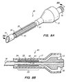
FIG. 8A is a perspective view of a ribbed sleeve and phaco-emulsification needle which is not part of the present invention; and -
FIG. 8B is a sectional view taken alongline 8B--8B of the phaco-smulsification needle ofFIG. 8A , showing the needle disposed within a sleeve. - Referring to
FIG. 1 , a previously known phaco-emulsification needle 10 is shown comprisinghub 12 andhollow shaft 14 extending fromhub 12. A threadedportion 16 extends away fromhub 12 on the proximal portion ofshaft 14, as is conventional.Shaft 14 terminates intip 18 at the distal end (i.e., remote from hub 12). -
Needle 10 contains a centralaxially extending lumen 13 through which material can be drawn from an eye using known techniques, as described hereinabove.Sleeve 17, which typically comprises a soft silicone material, is disposed overneedle 10 to form anannulus 19 through which liquid can be supplied to the anterior chamber of the eye during aspiration. As further described hereinabove,sleeve 17 can be compressed by the eye, and in particular, the portion surrounding the entry wound, to reduce liquid flow to an unacceptable extent. - Referring now to
FIGS. 2A and2B , phaco-emulsification needle 20 constructed in accordance with the present invention is described, in which like numbers denote like parts. As will of course be understood by one of skill in the art,FIGS. 2A and2B are not drawn to scale, but are provided merely for illustration.Needle 20, which is typically made of titanium, compriseshub 12,lumen 13, threadedportion 16,tip 18 andtubular portion 21 located inmid-region 25 betweentip 18 andhub 12. - Referring now also to
FIG. 3 ,tubular portion 21 illustratively comprises hollow reduced-circumferencecylindrical member 22 having a plurality of equispaced rib-like projections orflanges 24 extending radially outwardly from the outer surface ofmember 22. As shown inFIG. 2B , ifprojections 24 inmid-region 25 are alternatively viewed from the perspective of the outer diameter of the adjacent proximal and distal regions, the interstices betweenadjacent projections 24 appear as longitudinally-oriented channels orgrooves 30 in the outer surface ofneedle 20. -
Projections 24 on reduced-circumferencecylindrical member 22 may have their outer surfaces formed flush with the outer surface ofneedle 20 in the regions proximal and distal to mid-region 25 (as inFIG. 2B ), or extend slightly below or beyond the outer surface ofneedle 20 in the adjacent proximal and distal regions. To accommodate projections 24 (and thus grooves 30),lumen 13 may have a reduced diameter incentral region 25, as can be seen by comparison ofFIGS. 3 and 4 .Projections 24 and reduced-circumferencecylindrical member 22 may be disposed only in central ormid-region 25 ofneedle 20, which is the region typically subjected to compressive loading by the tissue surrounding the entry wound, or may alternatively extend along the entire outer surface ofneedle 20 to tip 18. - Disposed about and spaced from
tubular portion 21 issleeve 17, which may be formed of soft plastic or elastomeric material, for example, silicone. Whensleeve tube 17 is subjected to a compressive load and contacts needle 20,adjacent projections 24, together with the intervening portion of reduced-circumferencecylindrical member 22 and the inner surface ofsleeve 17, form channels orgrooves 30 which extend axially alongneedle 20. - Accordingly, if
needle 20 comes under pressure along itsmid-region 25 during a procedure of removing a cataract-effected lens, reduction in the cross-sectional areas of thechannels 30 is inhibited by the presence ofprojections 24. Liquid flow through thesleeve 17 viachannels 30 therefore can be maintained at a satisfactory level to replenish liquid removed by aspiration in the anterior chamber of the eye. - Moreover, no special external sleeves are required to ensure adequate
irrigation using needle 20. Thus, sealing between thesleeve 17 and entry wound may be accomplished with a previously knownsleeve 17 as described with respect toFIG. 1 , while maintaining the required wound size in the desired 2.5 - 3.2 mm range. -
Tubular portion 21 may be of a variety of shapes in cross-section, including circular and elliptical, and may have an outer circumference that is smaller than, the same as, or larger than the circumference of the adjacent proximal and distal portions ofneedle 20. In addition,central lumen 13 ofneedle 20 may have a single diameter over its entire length, or may be formed having a reduced diameter in the mid-region oftubular portion 21. - Likewise, projections 24 (and grooves 30) may be greater or fewer in number than shown in the accompanying figures, and form greater or lesser portions of the outer circumference of
central portion 25 than shown in the accompanying figures, which are to be understood as exemplary only. Moreover,projections 24 need not be spaced equidistant apart around the circumference oftubular portion 24, but may instead be concentrated on the upper and lower portions ofneedle 20, which are most likely to experience compressive loads. - Referring now to
FIGS. 5 and 6 , alternative embodiments of the phaco-emulsification needle of the present invention are shown, again in which like numbers denote like parts. InFIG. 5A , needle 20' has longitudinally-orientedprojections 24 that spiral around the circumference ofcylindrical member 22, thereby creating spiral channels. As illustrated inFIG. 5B ,projections 24 may be formed or machined to createhollow channels 26 that communicate withlumen 13, thereby increasing the flow area through the mid-portion of the needle. As will of course be understood by one of skill in the art, the rib-like projections 24 of any of the embodiments ofFIGS. 2-5 may advantageously includehollow channels 26. In addition, the channels may be disposed either in the mid-portion of the needle, or extend for the length of the entire inner surface of the needle. - In
FIG. 6 ,projections 24 onneedle 20 are formed as individual longitudinally-oriented diamond-shaped islands extending outward from the outer circumference ofcylindrical member 22, for example, by cross-cutting reverse-spiral grooves in the needle ofFIG. 5 . As will of course be understood by one of skill in the art,grooves 30 may be disposed in a needles 20' and 20'' by rotating the needle as thegrooves 30 are being formed. - In a preferred embodiment of the needle of
FIGS. 2-6 ,projections 24 andcylindrical member 22 may be formed by machining a single piece of titanium to the desired shape. Alternatively, a phaco-emulsification needle in accordance with the present invention may be formed from stainless steel, a suitably tough plastic composite, or a combination thereof. Likewise,projections 24 may be formed in any of a number of readily manufacturable configurations, for example, as circumferential channels with longitudinally-oriented communications, or even cylindrical nub-like shapes. - Referring now to
FIGS. 7A through 7D , alternative designs oftip 18 ofneedle 20 are illustrated.FIG. 7A showslumen 13 in the distal portion ofneedle 20 expanding to tip 18 in a funnel-like manner;FIG. 7B shows thelumen 13 having a curved horn-like shape as it expands to tip 18.FIGS. 7C and 7D illustrate alternative embodiments in which lumen 13 expands to tip 18 through a series ofmulti-chamber steps 13A-13B and 13A-13C. The foregoing lumen and tip configurations may be advantageously used with any of the phaco-emulsification needles of the present invention. - In
FIGS. 8A and 8B , a phaco-emulsification needle,needle 40, is depicted, which is not part of the present invention, in which like numbers denote like parts.Needle 40 includes reduced-circumference portion 21 inmid-region 25. Flanges orprojections 24 andcylindrical member 22 form aseparate insert 41 which is disposed on the reduced-circumference portion 21 ofneedle 40. -
Insert 41 may be formed of a soft plastic or elastomeric material, for example, silicone, and preferably is dimensioned so thatgap 42 forms between the inner surface ofcylindrical member 22 and the outer surface of reduced-circumference portion 21.Cylindrical member 22 may also include a longitudinal slit that permitscylindrical member 22 to be easily installed over reduced-circumference portion 21. - Alternatively,
cylindrical member 22 may be dimensioned to slip over a standard phaco-emulsification needle 10 as shown inFIG. 1 , but may then require the use of alarger sleeve 17 and larger entry wound. When installed on the either reduced-circumference portion 21 ofneedle 40 orstandard needle 10, insert 41 is expected to provide many of the advantages described hereinabove with respect to the needle embodiments ofFIGS. 2-6 . - Applicant has performed some closed chamber experiments employing a silicone model "eye" used in phaco-emulsification training workshops, in which the silicone "cornea" can be exchanged. In particular, applicant used a Series 10000 Master phaco-emulsification system, available from Alcon Surgical, Fort Worth, Texas, to compare the cooling performance of a needle constructed in accordance with the embodiment of
FIG. 2 to a standard Master phaco-emulsification needle. - The experiments were conducted using with a power setting of 70 on the Master system, a vacuum setting of 100 mmHg, a bottle height of 65 cm, an
irrigant flow rate 20 cc/min and an initial irrigant temperature of 25.6 °C. Varying the incision size from 2.75 mm to 4.1 mm in the silicone cornea (obtained using a keratome), the temperature of the sleeve at the point of compression by the incision was measured with a thermocouple for both the standard needle and the needle ofFIG. 2 after 15 seconds of operation. The results are shown in Table 1.TABLE 1 Sleeve Temperature °C Incision Size (mm) 2.75 Standard Needle 53 FIG. 2 Needle 373.00 50 32 3.25 47 32 3.50 44 30 4.10 33 28 - As will be observed from Table 1, the sleeve temperature was lower for the needle of
FIG. 2 at all incision sizes and always remained below 40 °C. In contrast, using the standard tip, the sleeve reached temperature levels exceeding fifty degrees -- a temperature at which thermal damage and collagen shrinkage would be expected to occur. - Applicant performed similar experiments in which the incision size was maintained at 3.00 mm and the flow rate was varied from 20 to 35 cc/min. While the performance of neither the standard needle nor the needle of
FIG. 2 varied much with change in irrigant flow rate, the sleeve temperature for the needle ofFIG. 2 was consistently about 20 °C lower than for the standard needle. In yet a third series of experiments, applicant kept the incision size at 3.00 mm and the flow rate constant at 20 cc/min and varied the irrigant bottle height from 65 to 75 cm. This also did not produce much an effect in the sleeve temperature for either needle, but again the sleeve temperature for the needle ofFIG. 2 was consistently about 20 °C lower than for the standard needle. - While preferred illustrative embodiments of the present invention are described above, it will be obvious to one skilled in the art that various changes and modifications may be made therein.
Claims (13)
- A phaco-emulsification system comprising:a phaco-emulsification needle (20); anda sleeve (17),wherein said phaco-emulsification needle (20) comprises:(i) a shaft (14) having a proximal end, a distal end, a first circumference, a mid-region (25) having a second circumference and a plurality of longitudinally-oriented outwardly extending projections (24) disposed from the second circumference, and a longitudinal lumen (13) extending through the shaft from the proximal end to the distal end,(ii) a hub (12) disposed at the proximal end of the shaft (14) and a threaded portion (16) proximal from the hub (12) and on the proximal portion of the shaft (14), the longitudinal lumen (13) extending through the hub (12) and the threaded portion (16), and(iii) a tip (18) disposed at the distal end of the shaft, the tip (18) having an opening communicating with the longitudinal lumen (13) for aspiration of fluid from the eye;wherein said needle shaft (14) is disposed within the sleeve (17); andwherein the adjacent projections (24) form channels therebetween for supplying fluid to the eye during aspiration even when the sleeve (17) is compressed against the needle shaft (14).
- The system as defined in claim 1, wherein the second circumference is smaller than the first circumference.
- The system as defined in any one of claim 1 or 2, wherein the projections (24) have an outer diameter, and the outer diameter of the projections (24) is flush with the first circumference.
- The system as defined in any one of claims 1-3, wherein the plurality of outwardly extending projections (24) extend radially outward from the second circumference.
- The system as defined in any one of claims 1-4, wherein the outwardly extending projections (24) form a plurality of ribs.
- The system as defined in claim 5, wherein the plurality of ribs are mutually parallel.
- The system as defined in claim 6, wherein the plurality of ribs spiral around the second circumference.
- The system as defined in any one of claims 5-7, wherein the plurality of ribs is spaced apart equidistant around the second circumference.
- The system as defined in claim 5, wherein the plurality of ribs define a plurality of grooves (30) in communication with one another.
- The system as defined in any one of claims 1 to 9, wherein the longitudinal lumen has a first cross-sectional area and, in the mid-region (25), the lumen (12) has a second cross-sectional area smaller than the first cross-sectional area.
- The system as defined in any one of claims 1 to 10, wherein the shaft is cylindrical.
- The system as defined in any one of claims 1 to 11, wherein the phaco-emulsification needle is made of titanium.
- The system as defined in any one of claims 1 to 12, wherein the longitudinal lumen (13) in the tip (18) is funnel-shaped, or horn-shaped, or has a multi-chambered stepped-shape.
Applications Claiming Priority (5)
| Application Number | Priority Date | Filing Date | Title |
|---|---|---|---|
| AUPM7844A AUPM784494A0 (en) | 1994-09-02 | 1994-09-02 | A phacoemulsification needle |
| AUPM784494 | 1994-09-02 | ||
| US486861 | 1995-06-07 | ||
| US08/486,861 US5718676A (en) | 1994-09-02 | 1995-06-07 | Grooved phaco-emulsification needle |
| EP95929677A EP0778757B1 (en) | 1994-09-02 | 1995-08-30 | Grooved phaco-emulsification needle |
Related Parent Applications (2)
| Application Number | Title | Priority Date | Filing Date |
|---|---|---|---|
| EP95929677A Division EP0778757B1 (en) | 1994-09-02 | 1995-08-30 | Grooved phaco-emulsification needle |
| EP95929677.3 Division | 1996-03-14 |
Publications (3)
| Publication Number | Publication Date |
|---|---|
| EP1371347A2 EP1371347A2 (en) | 2003-12-17 |
| EP1371347A3 EP1371347A3 (en) | 2005-06-01 |
| EP1371347B1 true EP1371347B1 (en) | 2011-02-09 |
Family
ID=25644757
Family Applications (2)
| Application Number | Title | Priority Date | Filing Date |
|---|---|---|---|
| EP03015611A Expired - Lifetime EP1371347B1 (en) | 1994-09-02 | 1995-08-30 | Grooved phaco-emulsification needle |
| EP95929677A Expired - Lifetime EP0778757B1 (en) | 1994-09-02 | 1995-08-30 | Grooved phaco-emulsification needle |
Family Applications After (1)
| Application Number | Title | Priority Date | Filing Date |
|---|---|---|---|
| EP95929677A Expired - Lifetime EP0778757B1 (en) | 1994-09-02 | 1995-08-30 | Grooved phaco-emulsification needle |
Country Status (11)
| Country | Link |
|---|---|
| US (2) | US5989209A (en) |
| EP (2) | EP1371347B1 (en) |
| JP (1) | JP3280671B2 (en) |
| AT (2) | ATE245013T1 (en) |
| AU (1) | AU684224B2 (en) |
| CA (1) | CA2198259C (en) |
| DE (1) | DE69531304T2 (en) |
| ES (1) | ES2200002T3 (en) |
| IL (1) | IL115139A (en) |
| IN (1) | IN185723B (en) |
| WO (1) | WO1996007377A1 (en) |
Cited By (2)
| Publication number | Priority date | Publication date | Assignee | Title |
|---|---|---|---|---|
| US8784361B2 (en) | 2010-12-07 | 2014-07-22 | Alcon Research, Ltd. | Combined coaxial and bimanual irrigation/aspiration apparatus |
| US9433725B2 (en) | 2011-12-23 | 2016-09-06 | Alcon Research, Ltd. | Combined coaxial and bimanual irrigation/aspiration apparatus |
Families Citing this family (95)
| Publication number | Priority date | Publication date | Assignee | Title |
|---|---|---|---|---|
| US5911699A (en) * | 1990-07-17 | 1999-06-15 | Aziz Yehia Anis | Removal of tissue |
| AUPO178796A0 (en) | 1996-08-22 | 1996-09-12 | Oversby Pty Ltd | Intraocular irrigation/aspiration device |
| US5676649A (en) * | 1996-10-04 | 1997-10-14 | Alcon Laboratories, Inc. | Phacoemulsification cutting tip |
| US6283974B1 (en) * | 1997-11-14 | 2001-09-04 | Aaron James Alexander | Surgical tip for phacoemulsification |
| US6165150A (en) * | 1997-12-29 | 2000-12-26 | Surgical Design Corporation | Tips for ultrasonic handpiece |
| WO1999044515A1 (en) * | 1998-03-02 | 1999-09-10 | Mentor Corporation | Ultrasonic liposuction probe |
| US6398759B1 (en) * | 1998-06-04 | 2002-06-04 | Alcon Manufacturing, Ltd. | Liquefracture handpiece tip |
| US6132436A (en) * | 1998-07-17 | 2000-10-17 | Allergan | Self-regulating phaco sleeve to reduce tissue burn |
| US6613056B1 (en) * | 1999-02-17 | 2003-09-02 | Misonix, Inc. | Ultrasonic probe with low-friction bushings |
| AU4420100A (en) * | 1999-04-21 | 2000-11-10 | Michael John Radley Young | Improved waveguide output configurations |
| US20050119679A1 (en) * | 1999-10-05 | 2005-06-02 | Omnisonics Medical Technologies, Inc. | Apparatus and method for an ultrasonic medical device to treat chronic total occlusions |
| US6551337B1 (en) | 1999-10-05 | 2003-04-22 | Omnisonics Medical Technologies, Inc. | Ultrasonic medical device operating in a transverse mode |
| US20050096669A1 (en) * | 1999-10-05 | 2005-05-05 | Omnisonics Medical Technologies, Inc. | Apparatus and method for an ultrasonic medical device to treat coronary thrombus bearing lesions |
| US20040249401A1 (en) * | 1999-10-05 | 2004-12-09 | Omnisonics Medical Technologies, Inc. | Apparatus and method for an ultrasonic medical device with a non-compliant balloon |
| US6733451B2 (en) | 1999-10-05 | 2004-05-11 | Omnisonics Medical Technologies, Inc. | Apparatus and method for an ultrasonic probe used with a pharmacological agent |
| US6660013B2 (en) | 1999-10-05 | 2003-12-09 | Omnisonics Medical Technologies, Inc. | Apparatus for removing plaque from blood vessels using ultrasonic energy |
| US20030236539A1 (en) * | 1999-10-05 | 2003-12-25 | Omnisonics Medical Technologies, Inc. | Apparatus and method for using an ultrasonic probe to clear a vascular access device |
| US20030065263A1 (en) * | 1999-10-05 | 2003-04-03 | Omnisonics Medical Technologies, Inc. | Ultrasonic probe device with rapid attachment and detachment means having a line contact collet |
| US20050043753A1 (en) * | 1999-10-05 | 2005-02-24 | Omnisonics Medical Technologies, Inc. | Apparatus and method for an ultrasonic medical device to treat peripheral artery disease |
| US20050043629A1 (en) * | 1999-10-05 | 2005-02-24 | Omnisonics Medical Technologies, Inc. | Apparatus and method for an ultrasonic medical device having a probe with a small proximal end |
| US6695782B2 (en) | 1999-10-05 | 2004-02-24 | Omnisonics Medical Technologies, Inc. | Ultrasonic probe device with rapid attachment and detachment means |
| EP1090658A1 (en) * | 1999-10-05 | 2001-04-11 | OmniSonics Medical Technologies | Ultrasonic medical treatment apparatus |
| US20040097996A1 (en) * | 1999-10-05 | 2004-05-20 | Omnisonics Medical Technologies, Inc. | Apparatus and method of removing occlusions using an ultrasonic medical device operating in a transverse mode |
| AU5943900A (en) * | 1999-11-29 | 2001-05-31 | Alcon Universal Limited | Torsional ultrasound handpiece |
| US6241710B1 (en) * | 1999-12-20 | 2001-06-05 | Tricardia Llc | Hypodermic needle with weeping tip and method of use |
| US6423074B1 (en) * | 1999-12-21 | 2002-07-23 | Allergan Sales, Inc. | Flexible irrigation/aspiration tip assembly for providing irrigation to an eye capsule and for aspirating fluid from the eye capsule |
| AUPQ644400A0 (en) | 2000-03-23 | 2000-04-20 | Oversby Pty Ltd | An aspiration flow modulation device |
| US6520929B2 (en) | 2000-04-20 | 2003-02-18 | Advanced Medical Optics | Infusion sleeve for ophthalmic surgery |
| US6638064B1 (en) * | 2000-06-07 | 2003-10-28 | Robert Scott Nance | Flexible endodontic syringe |
| US6527765B2 (en) * | 2000-10-06 | 2003-03-04 | Charles D. Kelman | Cryogenic surgical system and method of use in removal of tissue |
| US6533750B2 (en) * | 2001-01-23 | 2003-03-18 | Advanced Medical Optics | Conically shaped phaco tip |
| US6969373B2 (en) * | 2001-04-13 | 2005-11-29 | Tricardia, Llc | Syringe system |
| US7204828B2 (en) * | 2001-09-14 | 2007-04-17 | Zymequest, Inc. | Collection needle |
| JP3613634B2 (en) * | 2001-11-06 | 2005-01-26 | 得一郎 長谷川 | Vision correction device |
| US6852092B2 (en) * | 2002-10-02 | 2005-02-08 | Advanced Medical Optics, Inc. | Handpiece system for multiple phacoemulsification techniques |
| US7373850B2 (en) | 2002-11-08 | 2008-05-20 | Advanced Medical Optics, Inc. | Test chamber for bi-manual lens extraction |
| US20040199192A1 (en) * | 2003-04-04 | 2004-10-07 | Takayuki Akahoshi | Phacoemulsification needle |
| US20040199171A1 (en) * | 2003-04-04 | 2004-10-07 | Takayuki Akahoshi | Phacoemulsification needle |
| US20050020990A1 (en) * | 2003-04-04 | 2005-01-27 | Ravi Nallakrishnan | Phacoemulsification needle |
| US20060047254A1 (en) * | 2003-04-04 | 2006-03-02 | Ravi Nallakrishnan | Phacoemulsification needle |
| US7227095B2 (en) * | 2003-08-06 | 2007-06-05 | Micron Technology, Inc. | Wire bonders and methods of wire-bonding |
| US20050059939A1 (en) * | 2003-09-17 | 2005-03-17 | Perkins James T. | Phacoemulsification needle |
| US7794414B2 (en) | 2004-02-09 | 2010-09-14 | Emigrant Bank, N.A. | Apparatus and method for an ultrasonic medical device operating in torsional and transverse modes |
| WO2005092258A1 (en) * | 2004-03-25 | 2005-10-06 | Graham David Barrett | Phacoemulsification needle |
| US7947049B2 (en) * | 2004-03-31 | 2011-05-24 | Bausch & Lomb Incorporated | IOL injector |
| US7601136B2 (en) * | 2004-07-20 | 2009-10-13 | Takayuki Akahoshi | Infusion sleeve |
| US8876750B2 (en) * | 2004-09-27 | 2014-11-04 | Art, Limited | Coaxial tubing system for phacoemulsification handpieces |
| CH697759B1 (en) * | 2004-11-24 | 2009-02-13 | Oertli Instr Ag | Needle for an apparatus for phacoemulsification. |
| WO2006059183A1 (en) * | 2004-11-30 | 2006-06-08 | Bausch & Lomb Incorporated | Two stage plunger for intraocular lens injector |
| US7329261B2 (en) * | 2004-12-20 | 2008-02-12 | Bausch & Lomb Incorporated | No port phacoemulsification needle sleeve |
| US20080058708A1 (en) * | 2005-08-02 | 2008-03-06 | Takayuki Akahoshi | Phacoemulsification Needle |
| US8287484B2 (en) * | 2006-05-02 | 2012-10-16 | Abbott Medical Optics Inc. | Multi-purpose phacoemulsification needle |
| US20070260173A1 (en) | 2006-05-05 | 2007-11-08 | Alcon, Inc. | Irrigation/aspiration tip |
| US8333741B2 (en) * | 2006-11-10 | 2012-12-18 | Bausch & Lomb Incorporated | Phacoemulsification cannula with improved purchase |
| US20080269771A1 (en) * | 2007-04-26 | 2008-10-30 | Fulcher Samuel F A | Method and apparatus for ophthalmic surgery |
| US20090018596A1 (en) * | 2007-05-15 | 2009-01-15 | Cvrx, Inc. | Baroreflex activation therapy device with pacing cardiac electrical signal detection capability |
| WO2009032951A1 (en) | 2007-09-04 | 2009-03-12 | Marcus + Joy Llc | Protective sleeves for containers |
| US20100010419A1 (en) * | 2008-07-14 | 2010-01-14 | Takayuki Akahoshi | Phacoemulssification Needle Tips |
| US8308735B2 (en) * | 2008-10-06 | 2012-11-13 | Novartis Ag | Phacoemulsification tip with internal oriented structures |
| US9351871B2 (en) | 2008-11-12 | 2016-05-31 | Alcon Research, Ltd. | Distal plastic end infusion/aspiration tip |
| US20100125278A1 (en) * | 2008-11-19 | 2010-05-20 | Wagner Christopher E | Hard and Soft Tip Intraocular Lens Injector System and Method |
| NL2002379C2 (en) * | 2008-12-29 | 2010-06-30 | D O R C Dutch Ophthalmic Res Ct International B V | An ophthalmic device and an intravitreal method. |
| US8132683B2 (en) | 2009-05-13 | 2012-03-13 | Evenflo Company, Inc. | Protective bottle sling |
| US8623040B2 (en) * | 2009-07-01 | 2014-01-07 | Alcon Research, Ltd. | Phacoemulsification hook tip |
| US20110112466A1 (en) * | 2009-11-11 | 2011-05-12 | Ramon Carsola Dimalanta | Extended Point Phacoemulsification Tip |
| WO2011093674A2 (en) * | 2010-01-29 | 2011-08-04 | (주)유바이오메드 | Micro needle and micro needle device |
| US10258505B2 (en) | 2010-09-17 | 2019-04-16 | Alcon Research, Ltd. | Balanced phacoemulsification tip |
| US10106278B2 (en) | 2011-01-28 | 2018-10-23 | Aquavit Pharmaceuticals, Inc. | System and method for personalized injection treatment |
| KR101942597B1 (en) | 2011-01-28 | 2019-01-25 | 아쿠아빗 파마슈티컬즈, 아이엔씨. | System and method for personalized injection treatment |
| US9439807B2 (en) | 2011-09-26 | 2016-09-13 | Fluidics Partners, Llc | Apparatus and method for performing phacoemulsification |
| US20130085477A1 (en) * | 2011-09-29 | 2013-04-04 | Tyco Healthcare Group Lp | Catheter with tapering surfaces |
| US9149291B2 (en) | 2012-06-11 | 2015-10-06 | Tenex Health, Inc. | Systems and methods for tissue treatment |
| US11406415B2 (en) | 2012-06-11 | 2022-08-09 | Tenex Health, Inc. | Systems and methods for tissue treatment |
| US10980865B2 (en) * | 2012-08-10 | 2021-04-20 | Aquavit Pharmaceuticals, Inc. | Direct application system and method for the delivery of bioactive compositions and formulations |
| US9943439B2 (en) | 2012-10-26 | 2018-04-17 | Bausch & Lomb Incorporated | Irrigation sleeve and phacoemulsification needle with sleeve retention features |
| JP6320426B2 (en) * | 2013-01-24 | 2018-05-09 | デンツプライ シロナ インコーポレーテッド | Ultrasonic tip assembly |
| US9333114B2 (en) * | 2013-03-07 | 2016-05-10 | Fluidics Partners, Llc | Apparatus for performing phaco-emulsification |
| JP3185238U (en) * | 2013-05-28 | 2013-08-08 | Jmr株式会社 | Lens for ultrasonic emulsion suction |
| BR112015030230B1 (en) | 2013-06-06 | 2021-05-11 | Alcon Inc | suction/irrigation cannula device |
| CN104055620B (en) * | 2014-07-02 | 2016-03-30 | 以诺康医疗科技(苏州)有限公司 | Safety economy type ultrasonic emulsification syringe needle |
| US9962181B2 (en) | 2014-09-02 | 2018-05-08 | Tenex Health, Inc. | Subcutaneous wound debridement |
| US20160096040A1 (en) * | 2014-10-02 | 2016-04-07 | Tenex Health, Inc. | Laminated Needles and Methods of Making and Using Same |
| US10137033B2 (en) * | 2015-04-15 | 2018-11-27 | Moog Inc. | Torsional mode needle for phacoemulsification |
| US10932948B2 (en) * | 2015-04-20 | 2021-03-02 | Bausch & Lomb Incorporated | Ultrasonic needles and transducer assemblies formed of non-metal materials or a combination of materials |
| CN105310821A (en) | 2015-05-15 | 2016-02-10 | 以诺康医疗科技(苏州)有限公司 | Ultrasonic vitrectomy needle and device thereof |
| DE102015219062A1 (en) * | 2015-10-02 | 2017-04-06 | Geuder Ag | Hollow needle for an ophthalmological instrument |
| US10220195B2 (en) | 2016-06-08 | 2019-03-05 | Eclipse Medcorp, Llc | Radio frequency needling device for use with disposable needle cartridges |
| US9636491B1 (en) | 2016-06-08 | 2017-05-02 | Eclipse Aesthetics, LLC | Disposable needle cartridges having absorbing contaminant barriers |
| US9629991B1 (en) | 2016-06-08 | 2017-04-25 | Eclipse Aesthetics, LLC | Disposable radio frequency needle cartridges having absorbing containment barriers |
| CN106345051A (en) * | 2016-11-25 | 2017-01-25 | 崔丽林 | Miniature injection needle and integrated device thereof |
| US10478211B2 (en) * | 2017-07-07 | 2019-11-19 | Ethicon Llc | Features to promote removal of debris from within ultrasonic surgical instrument |
| DE102018200971B4 (en) * | 2018-01-23 | 2023-07-20 | Geuder Ag | Hollow needle for an ophthalmic surgical instrument and a sheath surrounding the hollow needle |
| US20200038242A1 (en) * | 2018-08-06 | 2020-02-06 | Nallakrishnan Family Trust | Apparatus and method for phacoemulsification |
| WO2021067306A1 (en) * | 2019-09-30 | 2021-04-08 | Gyrus Acmi, Inc. D/B/A Olympus Surgical Technologies America | Ultrasonic probe |
| US11202753B1 (en) | 2020-03-06 | 2021-12-21 | Aquavit Pharmaceuticals, Inc. | Systems and methods for generating immune responses in subjects using microchannel delivery devices |
Family Cites Families (41)
| Publication number | Priority date | Publication date | Assignee | Title |
|---|---|---|---|---|
| DE53855C (en) * | S. SEABURY, Lieutenant in der Marine der Vereinigten Staaten,von Nordamerika, Shuyler Place in Bergen Point, New-Jersey, V. St. A | Screw lock for rear loading guns with cartridge cases - ejector | ||
| DE332387C (en) * | 1921-02-04 | Reinhardt Willy Beckert | Wringing machine with rollers made from parts | |
| US3386438A (en) * | 1965-07-07 | 1968-06-04 | Roehr Products Company Inc | Tapered needle |
| NL145136C (en) * | 1967-07-25 | 1900-01-01 | ||
| US3732858A (en) * | 1968-09-16 | 1973-05-15 | Surgical Design Corp | Apparatus for removing blood clots, cataracts and other objects from the eye |
| SU602176A1 (en) * | 1973-06-18 | 1978-04-15 | Ростовский государственный медицинский институт | Tool for exerting ultrasonic action upon biological tissue |
| US4320761A (en) * | 1979-02-06 | 1982-03-23 | Haddad Heskel M | Surgical device for excision of tissue |
| FR2466994A1 (en) * | 1979-10-11 | 1981-04-17 | Emerit Andre | Medical needle directs liq. radially into or from flesh - partic. for intramuscular anaesthetic injection or draining venom from snake bite |
| SU1066583A1 (en) * | 1980-10-31 | 1984-01-15 | Ростовский Ордена Дружбы Народов Государственный Медицинский Институт | Ultrasonic instrument for acting on biologic tissue |
| DE3323867C2 (en) * | 1983-06-30 | 1986-07-10 | Hans-Peter Jasch | Surgical needle |
| US4515583A (en) * | 1983-10-17 | 1985-05-07 | Coopervision, Inc. | Operative elliptical probe for ultrasonic surgical instrument and method of its use |
| US4808154A (en) * | 1983-10-26 | 1989-02-28 | Freeman Jerre M | Phacoemulsification/irrigation and aspiration sleeve apparatus |
| US4634717A (en) * | 1984-05-01 | 1987-01-06 | Merck & Co., Inc. | Substituted-3-(2,3-dihydro-1H-inden-5-yl)-4-hydroxy-1H-pyrrole-2,5-diones, useful for treating persons with gray matter edema |
| US4634420A (en) * | 1984-10-31 | 1987-01-06 | United Sonics Incorporated | Apparatus and method for removing tissue mass from an organism |
| US4689040A (en) * | 1985-04-29 | 1987-08-25 | Thompson Robert J | Tip for a phacoemulsification needle |
| FR2584916B1 (en) * | 1985-07-19 | 1990-05-25 | Satelec Soc | APPARATUS FOR CURETYING OR EXERTING BIOLOGICAL TISSUES BY AN INSTRUMENT VIBRATING AT ULTRASONIC FREQUENCIES |
| US4816018A (en) * | 1985-08-02 | 1989-03-28 | Ultramed Corporation | Ultrasonic probe tip |
| US4643717A (en) * | 1985-09-16 | 1987-02-17 | Site Microsurgical Systems, Inc. | Aspiration fitting adaptor |
| US4634419A (en) * | 1985-12-13 | 1987-01-06 | Cooper Lasersonics, Inc. | Angulated ultrasonic surgical handpieces and method for their production |
| SU1715328A1 (en) * | 1987-02-12 | 1992-02-28 | Предприятие П/Я А-1687 | Ultrasonic instrument for affecting biological tissue preferentially in treating chronic tonsillitis |
| US5139504A (en) * | 1987-05-01 | 1992-08-18 | Ophthalmocare, Inc. | Apparatus, system, and method for softening and extracting cataractous tissue |
| WO1989005612A1 (en) * | 1987-12-24 | 1989-06-29 | Sumitomo Bakelite Company Limited | Excreting apparatus |
| GB8906898D0 (en) * | 1989-03-28 | 1989-05-10 | Young Michael J R | Tool for removal of plastics material |
| US4959049A (en) * | 1989-09-11 | 1990-09-25 | Smirmaul Heinz J | Tip for a phacoemulsification needle |
| US5038756A (en) * | 1989-10-30 | 1991-08-13 | Storz Instrument Company | Needle interface boot for ultrasonic surgical instrument |
| US5163433A (en) * | 1989-11-01 | 1992-11-17 | Olympus Optical Co., Ltd. | Ultrasound type treatment apparatus |
| US5071421A (en) * | 1990-02-08 | 1991-12-10 | Stahl Norman O | Method for preventing damage to tissue during ultrasonic surgery |
| US5205817A (en) * | 1990-05-17 | 1993-04-27 | Sumitomo Bakelite Company Limited | Surgical instrument |
| US5231569A (en) * | 1990-06-12 | 1993-07-27 | Sears Payment Systems, Inc. | Account transaction system |
| CA2071760A1 (en) * | 1991-09-23 | 1993-03-24 | Alexander Ureche | Infusion sleeve for surgical ultrasonic apparatus |
| US5178605A (en) * | 1991-09-23 | 1993-01-12 | Alcon Surgical, Inc. | Coaxial flow irrigating and aspirating ultrasonic handpiece |
| US5242385A (en) * | 1991-10-08 | 1993-09-07 | Surgical Design Corporation | Ultrasonic handpiece |
| US5188589A (en) * | 1991-10-10 | 1993-02-23 | Alcon Surgical, Inc. | Textured irrigating sleeve |
| US5199943A (en) * | 1991-12-12 | 1993-04-06 | Alcon Surgical, Inc. | Ultrasonic surgical handpiece |
| WO1993015703A1 (en) * | 1992-02-05 | 1993-08-19 | Inventive Systems, Inc. | Improved phacoemulsification handpiece |
| US5213569A (en) * | 1992-03-31 | 1993-05-25 | Davis Peter L | Tip for a tissue phacoemulsification device |
| US5300084A (en) * | 1992-11-23 | 1994-04-05 | United States Surgical Corporation | Pneumoperitoneum needle |
| US5286256A (en) * | 1992-12-30 | 1994-02-15 | Mackool Richard J | Fluid infusion sleeve |
| US5354265A (en) * | 1992-12-30 | 1994-10-11 | Mackool Richard J | Fluid infusion sleeve |
| US5464389A (en) * | 1993-08-10 | 1995-11-07 | Stahl; Norman O. | Working tip for fragmenting and aspirating ocular tissue |
| AUPM784494A0 (en) * | 1994-09-02 | 1994-09-22 | Oversby Pty Ltd | A phacoemulsification needle |
-
1995
- 1995-08-30 DE DE69531304T patent/DE69531304T2/en not_active Expired - Lifetime
- 1995-08-30 AU AU33365/95A patent/AU684224B2/en not_active Expired
- 1995-08-30 EP EP03015611A patent/EP1371347B1/en not_active Expired - Lifetime
- 1995-08-30 JP JP50903396A patent/JP3280671B2/en not_active Expired - Lifetime
- 1995-08-30 AT AT95929677T patent/ATE245013T1/en not_active IP Right Cessation
- 1995-08-30 CA CA002198259A patent/CA2198259C/en not_active Expired - Lifetime
- 1995-08-30 ES ES95929677T patent/ES2200002T3/en not_active Expired - Lifetime
- 1995-08-30 EP EP95929677A patent/EP0778757B1/en not_active Expired - Lifetime
- 1995-08-30 WO PCT/AU1995/000558 patent/WO1996007377A1/en active IP Right Grant
- 1995-08-30 AT AT03015611T patent/ATE497747T1/en not_active IP Right Cessation
- 1995-09-01 IL IL11513995A patent/IL115139A/en not_active IP Right Cessation
- 1995-09-04 IN IN1051CA1995 patent/IN185723B/en unknown
-
1997
- 1997-06-30 US US08/884,904 patent/US5989209A/en not_active Expired - Lifetime
- 1997-07-10 US US08/890,908 patent/US5935096A/en not_active Expired - Lifetime
Cited By (2)
| Publication number | Priority date | Publication date | Assignee | Title |
|---|---|---|---|---|
| US8784361B2 (en) | 2010-12-07 | 2014-07-22 | Alcon Research, Ltd. | Combined coaxial and bimanual irrigation/aspiration apparatus |
| US9433725B2 (en) | 2011-12-23 | 2016-09-06 | Alcon Research, Ltd. | Combined coaxial and bimanual irrigation/aspiration apparatus |
Also Published As
| Publication number | Publication date |
|---|---|
| CA2198259C (en) | 2006-08-15 |
| IL115139A0 (en) | 1995-12-31 |
| EP1371347A2 (en) | 2003-12-17 |
| ES2200002T3 (en) | 2004-03-01 |
| MX9701540A (en) | 1998-07-31 |
| ATE497747T1 (en) | 2011-02-15 |
| CA2198259A1 (en) | 1996-03-14 |
| EP1371347A3 (en) | 2005-06-01 |
| JP3280671B2 (en) | 2002-05-13 |
| WO1996007377A1 (en) | 1996-03-14 |
| IL115139A (en) | 1999-11-30 |
| ATE245013T1 (en) | 2003-08-15 |
| EP0778757A4 (en) | 2000-04-26 |
| US5989209A (en) | 1999-11-23 |
| IN185723B (en) | 2001-04-14 |
| US5935096A (en) | 1999-08-10 |
| EP0778757A1 (en) | 1997-06-18 |
| AU684224B2 (en) | 1997-12-04 |
| DE69531304D1 (en) | 2003-08-21 |
| EP0778757B1 (en) | 2003-07-16 |
| AU3336595A (en) | 1996-03-27 |
| JPH10507655A (en) | 1998-07-28 |
| DE69531304T2 (en) | 2004-03-04 |
Similar Documents
| Publication | Publication Date | Title |
|---|---|---|
| EP1371347B1 (en) | Grooved phaco-emulsification needle | |
| US5718676A (en) | Grooved phaco-emulsification needle | |
| EP0928177B1 (en) | Intraocular irrigation/aspiration device | |
| US20080188792A1 (en) | Phacoemulsification Needle | |
| EP0778750B1 (en) | Phacoemulsification handpiece, sleeve, and tip | |
| US6428501B1 (en) | Surgical instrument sleeve | |
| EP1835873B1 (en) | No port phacoemulsification needle sleeve | |
| EP2161046B1 (en) | Irrigation/aspiration system | |
| US7601136B2 (en) | Infusion sleeve | |
| EP0676931B1 (en) | New and improved fluid infusion sleeve | |
| AU2001255415A1 (en) | Infusion sleeve for ophthalmic surgery | |
| US20070027470A1 (en) | Surgical instrument | |
| MXPA97001540A (en) | Grooved needle for emulsification of f | |
| US7736329B2 (en) | Surgical instrument with a sleeve for use during eye surgery | |
| AU3841497A (en) | Intraocular irrigation/aspiration device | |
| Drews | Phacoemulsification Without Ultrasound |
Legal Events
| Date | Code | Title | Description |
|---|---|---|---|
| PUAI | Public reference made under article 153(3) epc to a published international application that has entered the european phase |
Free format text: ORIGINAL CODE: 0009012 |
|
| AC | Divisional application: reference to earlier application |
Ref document number: 0778757 Country of ref document: EP Kind code of ref document: P |
|
| AK | Designated contracting states |
Kind code of ref document: A2 Designated state(s): AT BE CH DE DK ES FR GB GR IE IT LI LU MC NL PT SE |
|
| RIN1 | Information on inventor provided before grant (corrected) |
Inventor name: BARRETT, GRAHAM D. |
|
| PUAL | Search report despatched |
Free format text: ORIGINAL CODE: 0009013 |
|
| AK | Designated contracting states |
Kind code of ref document: A3 Designated state(s): AT BE CH DE DK ES FR GB GR IE IT LI LU MC NL PT SE |
|
| RIC1 | Information provided on ipc code assigned before grant |
Ipc: 7A 61F 9/007 B Ipc: 7A 61F 9/00 A |
|
| 17P | Request for examination filed |
Effective date: 20050823 |
|
| AKX | Designation fees paid |
Designated state(s): AT BE CH DE DK ES FR GB GR IE IT LI LU MC NL PT SE |
|
| 17Q | First examination report despatched |
Effective date: 20091016 |
|
| GRAP | Despatch of communication of intention to grant a patent |
Free format text: ORIGINAL CODE: EPIDOSNIGR1 |
|
| GRAS | Grant fee paid |
Free format text: ORIGINAL CODE: EPIDOSNIGR3 |
|
| GRAA | (expected) grant |
Free format text: ORIGINAL CODE: 0009210 |
|
| AC | Divisional application: reference to earlier application |
Ref document number: 0778757 Country of ref document: EP Kind code of ref document: P |
|
| AK | Designated contracting states |
Kind code of ref document: B1 Designated state(s): AT BE CH DE DK ES FR GB GR IE IT LI LU MC NL PT SE |
|
| REG | Reference to a national code |
Ref country code: GB Ref legal event code: FG4D |
|
| REG | Reference to a national code |
Ref country code: CH Ref legal event code: EP |
|
| REG | Reference to a national code |
Ref country code: IE Ref legal event code: FG4D |
|
| REF | Corresponds to: |
Ref document number: 69536136 Country of ref document: DE Date of ref document: 20110324 Kind code of ref document: P |
|
| REG | Reference to a national code |
Ref country code: DE Ref legal event code: R096 Ref document number: 69536136 Country of ref document: DE Effective date: 20110324 |
|
| REG | Reference to a national code |
Ref country code: ES Ref legal event code: FG2A Ref document number: 2360087 Country of ref document: ES Kind code of ref document: T3 Effective date: 20110531 |
|
| REG | Reference to a national code |
Ref country code: NL Ref legal event code: VDEP Effective date: 20110209 |
|
| PG25 | Lapsed in a contracting state [announced via postgrant information from national office to epo] |
Ref country code: SE Free format text: LAPSE BECAUSE OF FAILURE TO SUBMIT A TRANSLATION OF THE DESCRIPTION OR TO PAY THE FEE WITHIN THE PRESCRIBED TIME-LIMIT Effective date: 20110209 Ref country code: PT Free format text: LAPSE BECAUSE OF FAILURE TO SUBMIT A TRANSLATION OF THE DESCRIPTION OR TO PAY THE FEE WITHIN THE PRESCRIBED TIME-LIMIT Effective date: 20110609 Ref country code: GR Free format text: LAPSE BECAUSE OF FAILURE TO SUBMIT A TRANSLATION OF THE DESCRIPTION OR TO PAY THE FEE WITHIN THE PRESCRIBED TIME-LIMIT Effective date: 20110510 |
|
| PG25 | Lapsed in a contracting state [announced via postgrant information from national office to epo] |
Ref country code: NL Free format text: LAPSE BECAUSE OF FAILURE TO SUBMIT A TRANSLATION OF THE DESCRIPTION OR TO PAY THE FEE WITHIN THE PRESCRIBED TIME-LIMIT Effective date: 20110209 Ref country code: AT Free format text: LAPSE BECAUSE OF FAILURE TO SUBMIT A TRANSLATION OF THE DESCRIPTION OR TO PAY THE FEE WITHIN THE PRESCRIBED TIME-LIMIT Effective date: 20110209 Ref country code: BE Free format text: LAPSE BECAUSE OF FAILURE TO SUBMIT A TRANSLATION OF THE DESCRIPTION OR TO PAY THE FEE WITHIN THE PRESCRIBED TIME-LIMIT Effective date: 20110209 |
|
| PG25 | Lapsed in a contracting state [announced via postgrant information from national office to epo] |
Ref country code: DK Free format text: LAPSE BECAUSE OF FAILURE TO SUBMIT A TRANSLATION OF THE DESCRIPTION OR TO PAY THE FEE WITHIN THE PRESCRIBED TIME-LIMIT Effective date: 20110209 |
|
| PLBE | No opposition filed within time limit |
Free format text: ORIGINAL CODE: 0009261 |
|
| STAA | Information on the status of an ep patent application or granted ep patent |
Free format text: STATUS: NO OPPOSITION FILED WITHIN TIME LIMIT |
|
| 26N | No opposition filed |
Effective date: 20111110 |
|
| REG | Reference to a national code |
Ref country code: DE Ref legal event code: R097 Ref document number: 69536136 Country of ref document: DE Effective date: 20111110 |
|
| PG25 | Lapsed in a contracting state [announced via postgrant information from national office to epo] |
Ref country code: MC Free format text: LAPSE BECAUSE OF NON-PAYMENT OF DUE FEES Effective date: 20110831 |
|
| REG | Reference to a national code |
Ref country code: CH Ref legal event code: PL |
|
| PG25 | Lapsed in a contracting state [announced via postgrant information from national office to epo] |
Ref country code: CH Free format text: LAPSE BECAUSE OF NON-PAYMENT OF DUE FEES Effective date: 20110831 Ref country code: LI Free format text: LAPSE BECAUSE OF NON-PAYMENT OF DUE FEES Effective date: 20110831 |
|
| REG | Reference to a national code |
Ref country code: IE Ref legal event code: MM4A |
|
| PG25 | Lapsed in a contracting state [announced via postgrant information from national office to epo] |
Ref country code: IE Free format text: LAPSE BECAUSE OF NON-PAYMENT OF DUE FEES Effective date: 20110830 |
|
| PG25 | Lapsed in a contracting state [announced via postgrant information from national office to epo] |
Ref country code: LU Free format text: LAPSE BECAUSE OF NON-PAYMENT OF DUE FEES Effective date: 20110830 |
|
| PGFP | Annual fee paid to national office [announced via postgrant information from national office to epo] |
Ref country code: DE Payment date: 20140901 Year of fee payment: 20 |
|
| PGFP | Annual fee paid to national office [announced via postgrant information from national office to epo] |
Ref country code: GB Payment date: 20140725 Year of fee payment: 20 Ref country code: FR Payment date: 20140725 Year of fee payment: 20 Ref country code: ES Payment date: 20140818 Year of fee payment: 20 |
|
| PGFP | Annual fee paid to national office [announced via postgrant information from national office to epo] |
Ref country code: IT Payment date: 20140820 Year of fee payment: 20 |
|
| REG | Reference to a national code |
Ref country code: DE Ref legal event code: R071 Ref document number: 69536136 Country of ref document: DE |
|
| REG | Reference to a national code |
Ref country code: GB Ref legal event code: PE20 Expiry date: 20150829 |
|
| PG25 | Lapsed in a contracting state [announced via postgrant information from national office to epo] |
Ref country code: GB Free format text: LAPSE BECAUSE OF EXPIRATION OF PROTECTION Effective date: 20150829 |
|
| REG | Reference to a national code |
Ref country code: ES Ref legal event code: FD2A Effective date: 20151204 |
|
| PG25 | Lapsed in a contracting state [announced via postgrant information from national office to epo] |
Ref country code: ES Free format text: LAPSE BECAUSE OF EXPIRATION OF PROTECTION Effective date: 20150831 |