EP1370397B1 - Shaving system for a dry shaver - Google Patents
Shaving system for a dry shaver Download PDFInfo
- Publication number
- EP1370397B1 EP1370397B1 EP02702346A EP02702346A EP1370397B1 EP 1370397 B1 EP1370397 B1 EP 1370397B1 EP 02702346 A EP02702346 A EP 02702346A EP 02702346 A EP02702346 A EP 02702346A EP 1370397 B1 EP1370397 B1 EP 1370397B1
- Authority
- EP
- European Patent Office
- Prior art keywords
- cutting
- teeth
- shaving
- cutting elements
- shaving system
- Prior art date
- Legal status (The legal status is an assumption and is not a legal conclusion. Google has not performed a legal analysis and makes no representation as to the accuracy of the status listed.)
- Expired - Lifetime
Links
- 238000005520 cutting process Methods 0.000 claims abstract description 104
- 230000036346 tooth eruption Effects 0.000 claims abstract description 11
- 210000004209 hair Anatomy 0.000 claims description 22
- 230000001154 acute effect Effects 0.000 claims description 3
- 210000001520 comb Anatomy 0.000 description 26
- 230000008878 coupling Effects 0.000 description 6
- 238000010168 coupling process Methods 0.000 description 6
- 238000005859 coupling reaction Methods 0.000 description 6
- 239000011888 foil Substances 0.000 description 3
- 229910000831 Steel Inorganic materials 0.000 description 2
- 238000005452 bending Methods 0.000 description 2
- 239000000969 carrier Substances 0.000 description 2
- 238000006073 displacement reaction Methods 0.000 description 2
- 230000000694 effects Effects 0.000 description 2
- 239000000314 lubricant Substances 0.000 description 2
- 239000002184 metal Substances 0.000 description 2
- 239000010959 steel Substances 0.000 description 2
- 238000011144 upstream manufacturing Methods 0.000 description 2
- 244000126211 Hericium coralloides Species 0.000 description 1
- 238000000429 assembly Methods 0.000 description 1
- 230000000712 assembly Effects 0.000 description 1
- 230000000295 complement effect Effects 0.000 description 1
- 230000003111 delayed effect Effects 0.000 description 1
- 239000000428 dust Substances 0.000 description 1
- 238000005530 etching Methods 0.000 description 1
- 238000002474 experimental method Methods 0.000 description 1
- 238000001746 injection moulding Methods 0.000 description 1
- 238000009434 installation Methods 0.000 description 1
- 238000000034 method Methods 0.000 description 1
- 230000008092 positive effect Effects 0.000 description 1
- 238000003825 pressing Methods 0.000 description 1
- 230000000284 resting effect Effects 0.000 description 1
Images


Classifications
-
- B—PERFORMING OPERATIONS; TRANSPORTING
- B26—HAND CUTTING TOOLS; CUTTING; SEVERING
- B26B—HAND-HELD CUTTING TOOLS NOT OTHERWISE PROVIDED FOR
- B26B19/00—Clippers or shavers operating with a plurality of cutting edges, e.g. hair clippers, dry shavers
- B26B19/02—Clippers or shavers operating with a plurality of cutting edges, e.g. hair clippers, dry shavers of the reciprocating-cutter type
- B26B19/04—Cutting heads therefor; Cutters therefor; Securing equipment thereof
- B26B19/10—Cutting heads therefor; Cutters therefor; Securing equipment thereof involving two or more different types of reciprocating cutting elements, e.g. a pair of toothed shearing elements combined with a pair of perforated cutting elements or a combined toothed and perforated cutting assembly
Definitions
- the invention relates to a shaving system for a dry shaver according to the preamble of claim 1.
- the central cutter has an upper knife with threading elements, which are aligned parallel to the skin to be shaved.
- the central cutter has an upper knife with threading elements, which are aligned parallel to the skin to be shaved.
- a shaving head according to the DE-OS 15 53 659 which shows two arranged between two Kurzhaarschneidsystemen long-hair trimmer, which are each folded in opposite directions of rotation by an angle of approximately 45 ° from the longitudinal plane of the razor.
- the invention is therefore an object of the invention to provide a skin-friendly working low-friction shear system with central cutter whose cutting properties ensures optimum cutting performance even when shaving of beard directly on the skin whiskers.
- the comb-shaped and perpendicular to the skin-oriented cutting elements of the long-hair trimmer allow both a tensing of the skin and a pre-combing the whiskers to be cut. Whiskers protruding from the skin are pre-combed by the long-hair trimmer and folded in the direction of the skin.
- the skin is tautened at the same time by contacting by means of the comb-shaped cutting elements.
- the shear system according to the invention provides that the long-hair trimmer consists of three cutting elements, wherein the central cutting element is movable relative to the two outer cutting elements, whereby a particularly skin-friendly and regardless of the direction of shaving particularly thorough shaving is possible.
- the cutting blade thus cuts on both sides between the two cutting combs.
- This symmetrical design ensures that both the combing of the whiskers and the tensing of the skin is always done with a stationary, that is not driven cutting comb, the moving cutting elements (the cutting blade) is now placed protected between the two cutting combs.
- the cutting teeth rows of the cutting elements are aligned parallel to each other, however, the cutting element planes are arranged in a downwardly opening acute angle to each other, resulting in a friction-reducing acting line between the cutting elements.
- the angle should be less than 5 °, preferably 2-3 °.
- the tooth base of at least one of the cutting teeth rows is lowered relative to the tooth base and at least one further tooth cutting row.
- a further advantageous embodiment of the invention provides that mutually facing side surfaces of the cutting elements are provided with a plurality of recesses and / or openings.
- This embodiment allows on the one hand the inclusion of lubricants to reduce friction, in addition, through these profiled side surfaces a hair between these side surfaces grated hair by the relative movement between the cutting elements and thus be removed. As a result, a bending or unfolding of the cutting elements in the cutting area can be prevented.
- the invention provided that adjacent cutting teeth rows have a different pitch.
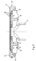
- Fig. 1 shows a cross section through an inventive shaving system in the form of a razor shaving head in the form of a removable frame 1, which can be connected in a conventional manner with the housing of a dry shaver.
- the removable frame 1 carries two U-shaped curved shear plates 2, which together with an associated lower blade 3, which is driven by a corresponding drive of the dry shaver, for example in the form of an electric motor provided in the housing of the dry shaver driven eccentric or a crank drive, oscillating , which form two shear units for the short haircut.
- the lower blade 3 are formed in a conventional manner as so-called blade tube blocks, which are made of a tubular steel element which has been processed by a plurality of transverse slots which extend approximately over half the diameter, so that the remaining webs sharp edged blades form.
- blade tube blocks which are made of a tubular steel element which has been processed by a plurality of transverse slots which extend approximately over half the diameter, so that the remaining webs sharp edged blades form.
- the two shear films 2 are attached with their downwardly pointing legs each at one of two outer webs 4 and one of two inner webs 5 of the removable frame 1 of the symmetrical to the center plane A shaving head.
- the outer and inner webs 4 and 5 are interconnected by side portions 6 of the removable frame 1.
- the long-hair trimmer 10 is arranged centrally, which is connected to the side portions 6 of the removable frame 1 by means of a Einklipsthetic.
- the long-hair trimmer 10 will now be described in detail with reference to the following figures in terms of structure and function.
- the cutting blade 12 and the two cutting combs 13 and 14 are made of a steel sheet, while the coupling element 11 is made of plastic.
- the cutting combs 13 and 14 are connected to a respective plastic carrier 15 and 16 respectively.
- the two assembled from cutting comb 13 and 14 and plastic carrier 15 and 16 assemblies are identical, so that they can be used twice per long hair trimmer 10, which can reduce the number of parts used. Due to this design similarity, the description of individual elements of this module of course applies to the corresponding second module.
- brackets 19 allow both a Vorspannkrafter Wegung as well as a pre-assembly of the long-hair trimmer.
- the cutting blade 12 has an upwardly and in the assembled state outwardly from the shaving head facing row of teeth 20, the teeth 21 are directed away from the coupling element 11.
- the cutting blade 12 is further provided with two elongated holes 22 which extend parallel to the row of teeth 20. These slots 22 are covered with a rim 23 made of plastic.
- the guide pins 24 have flat running surfaces 25 which extend in the same direction as the elongated holes 22, and two semi-circular end portions 26.
- Each plastic carrier 15, 16 has such a guide pin 24 which extends through the corresponding cutting comb 13, 14 therethrough. After assembly, it engages in a corresponding recess 27 of the complementary plastic carrier.
- the star-shaped clamping pin 28 which extends in the same direction as the guide pin 24 and is pressed for clamping in the bore 29 of the plastic carrier.
- the cutting combs 13, 14 Offset laterally outward relative to the recesses 27 or the guide pin 24, the cutting combs 13, 14 have through holes into which rivet heads 30, which are formed on the plastic carrier 15, 16, protrude.
- Each plastic carrier side has a cover 31, as the space between the two shaving foils 2 closes after installation of the trimmer, and an elastically deformable latching hook 32, which serves to lock the finished long-hair trimmer with the two side portions 6 of the removable frame 1.
- Each of the cutting blade 12 facing surface of the cutting comb 13 and 14 is provided with a plurality of recesses 33, on the one hand to receive lubricant to reduce friction; On the other hand, it also very quickly rubbed between these contact surfaces hair dust, whereby a gap in the cutting area or a bending of the cutting combs or the blade is prevented by a beard in this contact area beard hair.
- Fig. 5 shows a cutting blade 12, which with a plurality of recesses 40, which may also be formed as openings, at the two the associated cutting combs 13, 14 facing surfaces.
- the teeth of the row of teeth 20 are provided with openings or recesses 41, whereby the effect just mentioned is still increased. Both the recesses and the openings are produced by means of an etching process.
- the rows of teeth 34 of the cutting combs 13, 14 are formed in comparison to the row of teeth 20 of the cutting blade 12 with a much larger tooth height.
- the tooth tips 35 of the rows of teeth 34 project beyond the tooth tips of the row of teeth 20, whereby a particularly good combing of the beard to be shaved and raising possible flat hairs resting on the skin is achieved with maximum skin protection.
- This height difference of the tooth tips is especially in Fig. 4 clearly shown.
- the pitch of the row of teeth 20 is slightly larger than the pitch of the row of teeth 34, whereby a hooking between the cutting blade 12 and the cutting combs 15, 16 is prevented. At the same time, this difference in pitch ensures that not all of the cutting events occur simultaneously along the rows of teeth, resulting in a rounder run.
- Fig. 1 It can be seen that the cutting blade 12 is aligned so that it comes to rest in the center plane A.
- the cutting combs 13, 14 arranged laterally for this purpose are provided in one embodiment of the long-hair trimmer 10 in such a manner that they form an acute angle which opens downwards.
- the deviation from the center plane A is only a few degrees.
- This slight inclination of the cutting combs 13, 14 relative to the cutting blade 12 has the consequence that there is only a line of contact between the sliding metal parts, which significantly reduces the friction occurring against a flat support.
- the whiskers to be cut on the plastic supports 15, 16 of the rows of teeth 34 upstream combs 36 are formed with a rounded contour and with the rows of teeth 34 identical division.
- By appropriate pressing of these combs 36 to the skin to be shaved and a tensing of the skin can take place during shaving, whereby an optimal cutting result is favored.
- Fig. 3 shows, the teeth of the rows of teeth 34 of the cutting combs 13, 14 and those of these upstream combs 36 are aligned with each other, so that in the view shown there, the cutting comb 13 associated teeth including the Teeth of the combs 36 are covered by the cutting comb 14 associated teeth.
- the long-hair trimmer is characterized in that an offset is provided between said teeth. The maximum offset would thus be half the pitch of the rows of teeth 34.
- short hair When shaving with the shaving head described short hair are first shaved by means of Kurzhaarschneidsystems consisting of the shaving foil and the associated lower blade 3, while longer hair, which may also lie flat against the skin, are aligned by the long-hair trimmer 10 in the direction of shaving and between the cutting combs 13, 14 and the cutting blade 12 are cut off.
- the long-hair trimmer 10 following shorthair cutting then shaved off the shortened by the long-hair trimmer beard hair thoroughly.
Landscapes
- Life Sciences & Earth Sciences (AREA)
- Forests & Forestry (AREA)
- Engineering & Computer Science (AREA)
- Mechanical Engineering (AREA)
- Dry Shavers And Clippers (AREA)
- Drying Of Solid Materials (AREA)
Abstract
Description
Die Erfindung betrifft ein Schersystem für einen Trockenrasierer nach dem Oberbegriff des Patentanspruches 1.The invention relates to a shaving system for a dry shaver according to the preamble of
Aus der
Ein weiteres Schersystem ist aus der
Das gleiche gilt für einen Scherkopf gemäß der
Der Erfindung liegt daher die Aufgabe zugrunde, ein hautschonend arbeitendes reibungsarmes Schersystem mit Mittelschneider zu schaffen, dessen Schneideigenschaften auch bei der Rasur von direkt an der Haut anliegenden Barthaaren eine optimale Schneidleistung sicherstellt.The invention is therefore an object of the invention to provide a skin-friendly working low-friction shear system with central cutter whose cutting properties ensures optimum cutting performance even when shaving of beard directly on the skin whiskers.
Diese Aufgabe wird erfindungsgemäß durch die kennzeichnenden Merkmale des Anspruches 1 gelöst.This object is achieved by the characterizing features of
Die kammförmig ausgebildeten und senkrecht auf die Haut ausgerichteten Schneidelemente des Langhaarschneiders ermöglichen sowohl ein Abspannen der Haut sowie ein Vorkämmen der zu schneidenden Barthaare. Von der Haut abstehende Barthaare werden durch den Langhaarschneider vorgekämmt und in Richtung auf die Haut umgelegt. Die Haut wird dabei durch das Kontaktieren mittels der kammförmigen Schneidelemente gleichzeitig abgespannt. Überraschenderweise hat sich in praktischen Rasierversuchen gezeigt, daß die erfindungsgemäße Ausrichtung der Schneidelemente keine negativen Auswirkungen auf die Hautschonung während der Rasur hat.The comb-shaped and perpendicular to the skin-oriented cutting elements of the long-hair trimmer allow both a tensing of the skin and a pre-combing the whiskers to be cut. Whiskers protruding from the skin are pre-combed by the long-hair trimmer and folded in the direction of the skin. The skin is tautened at the same time by contacting by means of the comb-shaped cutting elements. Surprisingly, it has been shown in practical shaving experiments that the inventive Alignment of the cutting elements has no negative effect on the skin care during shaving.
Das erfindungsgemäße Schersystem sieht vor, daß der Langhaarschneider aus drei Schneidelementen besteht, wobei das mittlere Schneidelement relativ zu den beiden äußeren Schneidelementen bewegbar ist, wodurch ein besonders hautschonendes und unabhängig von der Rasierrichtung besonders gründliches Rasieren ermöglicht wird. Die Schneidklinge schneidet somit beidseitig zwischen den beiden Schneidkämmen. Diese symmetrische Ausführung stellt sicher, daß sowohl das Vorkämmen der Barthaare als auch das Abspannen der Haut stets mit einem ruhenden, also nicht angetriebenen Schneidkamm erfolgt, wobei das bewegte Schneidelemente (die Schneidklinge) jetzt geschützt zwischen den beiden Schneidkämmen angeordnet ist.The shear system according to the invention provides that the long-hair trimmer consists of three cutting elements, wherein the central cutting element is movable relative to the two outer cutting elements, whereby a particularly skin-friendly and regardless of the direction of shaving particularly thorough shaving is possible. The cutting blade thus cuts on both sides between the two cutting combs. This symmetrical design ensures that both the combing of the whiskers and the tensing of the skin is always done with a stationary, that is not driven cutting comb, the moving cutting elements (the cutting blade) is now placed protected between the two cutting combs.
Die Schneidzahnreihen der Schneidelemente sind parallel zueinander ausgerichtet, die Schneidelementeebenen werden jedoch in einem sich nach unten öffenden spitzen Winkel zueinander angeordnet, wodurch sich eine reibungsmindernd wirkende Berührungslinie zwischen den Schneidelementen ergibt. Der Winkel sollte dabei kleiner als 5°, vorzugsweise 2-3° betragen.The cutting teeth rows of the cutting elements are aligned parallel to each other, however, the cutting element planes are arranged in a downwardly opening acute angle to each other, resulting in a friction-reducing acting line between the cutting elements. The angle should be less than 5 °, preferably 2-3 °.
Besonders positiv auf das Einfädelverhalten von Barthaaren wirkt es sich aus, wenn die Zahnspitzen eines der Schneidelemente gegenüber den Zahnspitzen mindestens eines weiteren Schneidelementes in Bezug auf die zu rasierende Hautfläche abgesenkt ist. Um eine optimale Hautschonung und ein bestmögliches Einfädelverhalten der Barthaare unabhängig von der Rasierrichtung zu erhalten, ist es von Vorteil, wenn das mittlere Schneidelement gegenüber den äußeren Schneidelementen abgesenkt ist.It has a particularly positive effect on the threading behavior of whiskers when the tooth tips of one of the cutting elements are lowered relative to the tooth tips of at least one further cutting element with respect to the skin surface to be shaved. In order to obtain optimal skin care and the best possible Einfädelverhalten the beard hair regardless of the direction of shaving, it is advantageous if the central cutting element is lowered relative to the outer cutting elements.
Um abgeschnittene oder eingefädelte Haare möglichst schnell aus dem Schneidbereich zu entfernen, ist es von Vorteil, wenn der Zahngrund mindestens eines der Schneidzahnreihen gegenüber dem Zahngrund und mindestens einer weiteren Zahnschneidreihe abgesenkt ist.In order to remove cut or threaded hair as quickly as possible from the cutting area, it is advantageous if the tooth base of at least one of the cutting teeth rows is lowered relative to the tooth base and at least one further tooth cutting row.
Eine weitere vorteilhafte Ausführungsform der Erfindung sieht vor, daß einander zugewandte Seitenflächen der Schneidelemente mit einer Vielzahl von Ausnehmungen und/oder Durchbrüchen versehen sind. Diese Ausführung ermöglicht zum einen die Aufnahme von Schmiermitteln zur Reibungsverringerung, darüber hinaus kann durch diese profilierten Seitenflächen ein zwischen diese Seitenflächen gelangtes Haar durch die Relativbewegung zwischen den Schneidelementen zerrieben und damit entfernt werden. Dadurch läßt sich ein Aufbiegen oder Aufklappen der Schneidelemente im Schneidbereich verhindern.A further advantageous embodiment of the invention provides that mutually facing side surfaces of the cutting elements are provided with a plurality of recesses and / or openings. This embodiment allows on the one hand the inclusion of lubricants to reduce friction, in addition, through these profiled side surfaces a hair between these side surfaces grated hair by the relative movement between the cutting elements and thus be removed. As a result, a bending or unfolding of the cutting elements in the cutting area can be prevented.
Um ein Verhaken der Schneidzähne zu vermeiden und ein Verteilen der Schneidereignisse entlang der Schneidzahnreihen zu erreichen, ist bei einer weiteren bevorzugten Ausführungsform der Erfindung vorgesehen, daß benachbarte Schneidzahnreihen eine unterschiedliche Teilung aufweisen.In order to avoid snagging of the cutting teeth and to achieve distribution of the cutting events along the rows of cutting teeth, in another preferred embodiment the invention provided that adjacent cutting teeth rows have a different pitch.
Weitere Ziele, Merkmale, Vorteile und Anwendungsmöglichkeiten der vorliegenden Erfindung ergeben sich aus der nachfolgenden Beschreibung der Ausführungsbeispiele. Dabei bilden alle beschriebenen oder bildlich dargestellten Merkmale für sich oder in beliebiger Kombination den Gegenstand vorliegender Erfindung, auch unabhängig von ihrer Zusammenfassung in den Ansprüchen oder deren Rückbeziehung.Other objects, features, advantages and applications of the present invention will become apparent from the following description of the embodiments. All described or illustrated features alone or in any combination form the subject matter of the present invention, regardless of their inclusion in the claims or their dependency.
- Fig. 1Fig. 1
- einen Querschnitt durch ein erfindungsgemäßes Schersystem,a cross section through a shear system according to the invention,
- Fig. 2Fig. 2
- eine Explosionsdarstellung des erfindungsgemäßen Mittelschneiders,an exploded view of the center cutter according to the invention,
- Fig. 3Fig. 3
-
eine Seitenansicht des Langhaarschneiders gemäß
Fig. 2 in montiertem Zustand,a side view of the long-hair trimmer according toFig. 2 in assembled condition, - Fig. 4Fig. 4
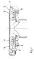
- zeigt einen teilmontierten Langhaarschneider undshows a partially assembled long hair trimmer and
- Fig. 5Fig. 5
- eine perspektivische Darstellung einer speziellen Ausführungsform der zentralen Schneidklinge.a perspective view of a specific embodiment of the central cutting blade.
Die Untermesser 3 sind in an sich bekannter Weise als sogenannte Messerrohrblöcke ausgebildet, die aus einem rohrförmigen Stahlelement hergestellt werden, das durch eine Vielzahl von quer verlaufenden Schlitzen, die sich etwa über den halben Durchmesser erstrekken, derart bearbeitet wurde, daß die verbleibenden Stege scharfkantige Klingen bilden. Auf der von der Scherfolie 2 abgewandten Seite der Untermesser 3 sind jeweils Kupplungselemente angebracht, die in montierten Zustand die Untermesser mit dem Antrieb in Eingriff bringen.The
In der Zeichnung ist lediglich eines der beiden Untermesser 3 gezeigt. Der Antrieb sowie das Gehäuse des Trockenrasierers wurden der Übersichtlichkeit halber ebenfalls zeichnerisch nicht dargestellt.In the drawing, only one of the two
Die beiden Scherfolien 2 sind mit ihren nach unten weisenden Schenkeln jeweils an einem von zwei Außenstegen 4 und einem von zwei Innenstegen 5 des Wechselrahmens 1 des zur Mittelebene A symmetrischen Scherkopfes befestigt. Die Außen- und Innenstege 4 bzw. 5 sind durch Seitenabschnitte 6 des Wechselrahmens 1 miteinander verbunden.The two
Zwischen den beiden Scherfolien 2, welche zusammen mit den zugeordneten Untermessern 3 die Schneideinheiten für den Kurzhaarschnitt bilden, ist der Langhaarschneider 10 mittig angeordnet, welcher mit den Seitenabschnitten 6 des Wechselrahmens 1 mittels einer Einklipsverbindung verbunden ist. Der Langhaarschneider 10 wird nun anhand der folgenden Figuren in Bezug auf Struktur und Funktion näher beschrieben.Between the two
Sämtliche Figuren zeigen deutlich das Kupplungselement 11, welches mit dem zentralen Schneidelement, nämlich der Schneidklinge 12 fest verbunden ist, wobei das Kupplungselement 11 nach dem Befestigen des Wechselrahmens 1 am Gehäuse des Trockenrasierers mit dem Antrieb des Trockenrasierers zum oszillierenden Betätigen der Schneidklinge 12 in Eingriff gebracht wird. Dieser Eingriff kann entweder unmittelbar oder mittelbar, etwa durch Einkoppeln der Schneidklinge 12 in ein mit einem der Untermesser 3 verbundenes Bauteil erfolgen. Wie
Die Schneidklinge 12 sowie die beiden Schneidkämme 13 und 14 sind aus einem Stahlblech hergestellt, während das Kupplungselement 11 aus Kunststoff besteht. Die Schneidkämme 13 und 14 sind mit jeweils einem Kunststoffträger 15 bzw. 16 verbunden. Die beiden aus Schneidkamm 13 bzw. 14 und Kunststoffträger 15 bzw. 16 zusammengesetzten Baugruppen sind dabei identisch ausgeführt, sodaß sie pro Langhaarschneider 10 zweimal verwendet werden können, wodurch sich die Anzahl der verwendeten Teile reduzieren läßt. Aufgrund dieser Baugleichheit gilt die Beschreibung einzelner Elemente dieser Baugruppe natürlich auch für die entsprechende zweite Baugruppe.The
Auf den den Schneidkämmen 13, 14 abgewandten Seiten besitzen die Kunststoffträger 15, 16 Ausnehmungen 17, zur Aufnahme der gewölbten Enden 18 der Klammern 19, welche die beiden äußeren Schneidelemente unter elastischer Vorspannung gegen das mittlere Schneidelement andrücken. Somit ermöglichen die Klammern 19 sowohl eine Vorspannkrafterzeugung als auch eine Vormontage des Langhaarschneiders.On the
Die Schneidklinge 12 besitzt eine nach oben und in montiertem Zustand nach außen aus dem Scherkopf weisende Zahnreihe 20, deren Zähne 21 vom Kupplungselement 11 fortgerichtet sind. Die Schneidklinge 12 ist ferner mit zwei Langlöchern 22 versehen, die sich parallel zur Zahnreihe 20 erstrecken. Diese Langlöcher 22 sind mit einem Rand 23 aus Kunststoff verkleidet. Mittels der Langlöcher 22 wird die Schneidklinge 12 auf Führungsbolzen 24 geführt, so daß lediglich ein begrenztes Verschieben parallel zur Zahnreihe 20 möglich ist. Die Führungsbolzen 24 besitzen ebene Laufflächen 25, die sich in die gleiche Richtung wie die Langlöcher 22 erstrecken, sowie zwei halbkreisförmige Endbereiche 26. Jeder Kunststoffträger 15, 16 besitzt einen solchen Führungsbolzen 24, der sich durch den entsprechenden Schneidkamm 13, 14 hindurch erstreckt. Nach der Montage greift er in eine entsprechende Ausnehmung 27 des komplementären Kunststoffträgers ein.The
Zur paßgenauen Montage und Befestigung der beiden Kunststoffträger 15 und 16 miteinander dient der sternförmige Klemmstift 28, welcher sich in die gleiche Richtung wie der Führungsbolzen 24 erstreckt und zum Verklemmen in die Bohrung 29 der Kunststoffträger gepreßt wird. Gegenüber den Ausnehmungen 27 bzw. dem Führungsbolzen 24 seitlich nach außen versetzt, besitzen die Schneidkämme 13, 14 Durchgangsbohrungen, in welche Nietköpfe 30, welche am Kunststoffträger 15, 16 angeformt sind, hineinragen. Diese dienen der Befestigung der Schneidkämme an den Kunststoffträgern und werden mittels eines sogenannten Warmverstemmvorganges bei der Montage durch Wärmebeaufschlagung erhitzt und anschließend wie ein Nietkopf 30 derart verformt, daß kein Überstand über die Schneidkämme in Richtung auf die Schneidklinge besteht, um ein freies Verschieben der Schneidklinge 12 relativ zu den Schneidkämmen 13 sicherzustellen; innerhalb der Durchgangsbohrungen jedoch werden die Nietköpfe 30 so verformt, daß eine radiale Klemmkraft zwischen dem Kunststoffteil und dem metallenen Schneidkamm bestehen bleibt. Die Kunststoffträger 15, 16 können jedoch auch durch Spritzguß direkt an die Schneidkämme 13, 14 angeformt werden.For accurate fit assembly and attachment of the two
Seitlich besitzt jeder Kunststoffträger eine Abdeckung 31, wie den Raum zwischen den beiden Scherfolien 2 nach Einbau des Langhaarschneiders verschließt, sowie einen elastisch verformbaren Rasthaken 32, der dem Verrasten des fertigmontierten Langhaarschneiders mit den beiden Seitenabschnitten 6 des Wechselrahmens 1 dient.Each plastic carrier side has a
Die jeweils der Schneidklinge 12 zugewandte Fläche des Schneidkammes 13 und 14 ist mit einer Vielzahl von Ausnehmungen 33 versehen, um einerseits Schmiermittel zur Reibungsverringerung aufzunehmen; andererseits wird hierdurch auch zwischen diese Kontaktflächen gelangter Haarstaub sehr schnell zerrieben, wodurch ein Spalt im Schneidbereich oder eine Aufbiegung der Schneidkämme bzw. der Klinge durch ein in diesen Kontaktbereich gelangtes Barthaar verhindert wird.Each of the
Die Zahnreihen 34 der Schneidkämme 13, 14 sind im Vergleich zur Zahnreihe 20 der Schneidklinge 12 mit einer deutlich größeren Zahnhöhe ausgebildet. In montiertem Zustand überragen die Zahnspitzen 35 der Zahnreihen 34 die Zahnspitzen der Zahnreihe 20, wodurch bei maximaler Hautschonung ein besonders gutes Durchkämmen des zu rasierenden Bartes und ein Aufrichten eventuelle flach auf der Haut anliegender Barthaare erreicht wird. Diese Höhendifferenz der Zahnspitzen wird insbesondere in
Wie insbesondere in
In
Als Hautschutz und zum besonders hautfreundlichen Vorkämmen der zu schneidenden Barthaare sind an den Kunststoffträgern 15, 16 den Zahnreihen 34 vorgelagerte Kämme 36 mit abgerundeter Kontur und mit zu den Zahnreihen 34 identischer Teilung angeformt. Durch entsprechendes Andrücken dieser Kämme 36 an die zu rasierende Haut kann auch ein Abspannen der Haut während des Rasierens erfolgen, wodurch ein optimales Schneidergebnis begünstigt wird. Hierzu ist es besonders vorteilhaft, wenn die Zähne der Kämme 36 in Bezug auf die Zähne der Zahnreihe 34 um einen Winkel von ca. 45° nach außen, daß heißt gemäß der in
Wie
Bei der Rasur mit dem beschriebenen Scherkopf werden zunächst mittels des Kurzhaarschneidsystems, welches aus der Scherfolie und dem zugeordneten Untermesser 3 besteht, kurze Haare ausrasiert, während längere Haare, die eventuell auch flach an der Haut aufliegen, durch den Langhaarschneider 10 in Rasierrichtung ausgerichtet werden und zwischen den Schneidkämmen 13, 14 und der Schneidklinge 12 abgeschnitten werden. Das dem Langhaarschneider 10 folgende Kurzhaarschneidsystem rasiert dann das durch den Langhaarschneider gekürzte Barthaar gründlich aus.When shaving with the shaving head described short hair are first shaved by means of Kurzhaarschneidsystems consisting of the shaving foil and the associated
Claims (7)
- A shaving system for an electric razor made up of at least one long hair trimmer (10) situated between shaving units for cutting short hair, the shaving units for cutting short hair each being made up of an upper blade and a lower blade (2, 3) that are movable relative to one another by a drive, and the long hair trimmer being made up of at least two cutting elements (12, 13, 14) that are movable relative to one another and are situated alongside one another, the cutting elements (12, 13, 14) of the long hair trimmer each being fashioned in the shape of a comb, and their rows of cutting teeth (20, 34), formed by tines, being oriented so as to point toward the skin to be shaved, essentially perpendicular thereto, and the long hair trimmer (10) being made up of three cutting elements (12, 13, 14), the center cutting element (12) being movable relative to the two outer cutting elements (13, 14), characterized in that the rows of cutting teeth (20, 34) of the cutting elements are oriented parallel to one another, but the planes of the cutting elements run at an acute angle to one another, opening downward.
- The shaving system according to Claim 1, characterized in that the angle is smaller than 5°, preferably 2 to 3°.
- The shaving system according to one of the preceding claims, characterized in that the tips of the teeth of one of the cutting elements (12) are lowered relative to the tips of the teeth (35) of at least one additional cutting element (13, 14) relative to the skin surface that is to be shaved.
- The shaving system according to one of the preceding claims, characterized in that the center cutting element (12) is lowered relative to the outer cutting elements (13, 14).
- The shaving system according to one of the preceding claims, characterized in that the tooth base of at least one of the rows of cutting teeth (34) is lowered relative to the tooth base of at least one additional row of cutting teeth (20).
- The shaving system according to one of the preceding claims, characterized in that side surfaces facing one another of the cutting elements (12, 13, 14) are provided with a multiplicity of recesses (33, 40) and/or breaches (41).
- The shaving system according to one of the preceding claims, characterized in that adjacent rows of cutting teeth (20, 34) have different gappings.
Applications Claiming Priority (3)
| Application Number | Priority Date | Filing Date | Title |
|---|---|---|---|
| DE10110228 | 2001-03-02 | ||
| DE10110228A DE10110228C1 (en) | 2001-03-02 | 2001-03-02 | Shaving system for a dry shaver with a long hair cutter |
| PCT/EP2002/001189 WO2002070212A1 (en) | 2001-03-02 | 2002-02-06 | Shearing system for a dry shaver |
Publications (2)
| Publication Number | Publication Date |
|---|---|
| EP1370397A1 EP1370397A1 (en) | 2003-12-17 |
| EP1370397B1 true EP1370397B1 (en) | 2009-11-25 |
Family
ID=7676162
Family Applications (1)
| Application Number | Title | Priority Date | Filing Date |
|---|---|---|---|
| EP02702346A Expired - Lifetime EP1370397B1 (en) | 2001-03-02 | 2002-02-06 | Shaving system for a dry shaver |
Country Status (7)
| Country | Link |
|---|---|
| US (1) | US6889437B2 (en) |
| EP (1) | EP1370397B1 (en) |
| JP (1) | JP4204320B2 (en) |
| CN (1) | CN1264658C (en) |
| AT (1) | ATE449673T1 (en) |
| DE (2) | DE10110228C1 (en) |
| WO (1) | WO2002070212A1 (en) |
Families Citing this family (12)
| Publication number | Priority date | Publication date | Assignee | Title |
|---|---|---|---|---|
| CA2546434C (en) | 2003-11-20 | 2013-01-22 | The Henry M. Jackson Foundation For The Advancement Of Military Medicine , Inc. | Portable hand pump for evacuation of fluids |
| US8104178B2 (en) * | 2003-12-04 | 2012-01-31 | Wella GmbH | Cutting head for an electric hair cutting machine |
| US8337475B2 (en) | 2004-10-12 | 2012-12-25 | C. R. Bard, Inc. | Corporeal drainage system |
| US20070089578A1 (en) * | 2005-10-24 | 2007-04-26 | Zoot Ivan K | Blade having guide marks |
| KR20100008088U (en) * | 2009-02-05 | 2010-08-13 | 오태준 | A comb of shaver-net of reciprocation type electrical shaver |
| JP6376427B2 (en) * | 2012-12-27 | 2018-08-22 | パナソニックIpマネジメント株式会社 | Slit blade block and electric razor having slit blade block |
| US20150314461A1 (en) * | 2014-05-02 | 2015-11-05 | Raymond Industrial Ltd. | Hybrid Shaving System |
| US10647010B2 (en) * | 2014-07-04 | 2020-05-12 | Koninklijke Philips N.V. | Blade set, hair cutting appliance, and related manufacturing method |
| EP3527339A1 (en) | 2018-02-20 | 2019-08-21 | Koninklijke Philips N.V. | A comb for a hair cutting appliance |
| EP3907047B1 (en) | 2020-05-08 | 2025-04-16 | Braun GmbH | Electric beard trimmer |
| EP3907048B1 (en) | 2020-05-08 | 2023-03-22 | Braun GmbH | Electric beard trimmer |
| WO2026066029A1 (en) * | 2024-09-24 | 2026-04-02 | 深圳术叶创新科技有限公司 | Cutter head device and hair trimmer |
Family Cites Families (7)
| Publication number | Priority date | Publication date | Assignee | Title |
|---|---|---|---|---|
| DE1553659A1 (en) * | 1967-06-24 | 1971-05-27 | Braun Ag | Electrically powered dry shaver with two shaving heads for short haircuts |
| US3589005A (en) * | 1969-02-07 | 1971-06-29 | Braun Ag | Electric shaver |
| DE3428487C2 (en) * | 1984-08-02 | 1986-08-21 | Braun Ag, 6000 Frankfurt | Long hair trimmer for dry razors |
| US5398412A (en) * | 1992-04-23 | 1995-03-21 | Matsushita Electric Works, Ltd. | Reciprocatory dry shaver |
| JPH05293259A (en) * | 1992-04-23 | 1993-11-09 | Matsushita Electric Works Ltd | Reciprocating electric shaver |
| DE4312060C1 (en) * | 1993-04-13 | 1994-06-01 | Braun Ag | Cutting head for electric shaver - has drawing-in elements with freely projecting ends which execute combing function, and forming top blade contact surface |
| JPH10235035A (en) * | 1997-02-25 | 1998-09-08 | Tec Corp | Electric shaver |
-
2001
- 2001-03-02 DE DE10110228A patent/DE10110228C1/en not_active Expired - Fee Related
-
2002
- 2002-02-06 WO PCT/EP2002/001189 patent/WO2002070212A1/en not_active Ceased
- 2002-02-06 EP EP02702346A patent/EP1370397B1/en not_active Expired - Lifetime
- 2002-02-06 CN CN02805826.7A patent/CN1264658C/en not_active Expired - Fee Related
- 2002-02-06 AT AT02702346T patent/ATE449673T1/en active
- 2002-02-06 JP JP2002569361A patent/JP4204320B2/en not_active Expired - Fee Related
- 2002-02-06 DE DE50214024T patent/DE50214024D1/en not_active Expired - Lifetime
-
2003
- 2003-09-02 US US10/653,402 patent/US6889437B2/en not_active Expired - Lifetime
Also Published As
| Publication number | Publication date |
|---|---|
| CN1264658C (en) | 2006-07-19 |
| ATE449673T1 (en) | 2009-12-15 |
| DE10110228C1 (en) | 2002-08-01 |
| JP4204320B2 (en) | 2009-01-07 |
| US20040040157A1 (en) | 2004-03-04 |
| DE50214024D1 (en) | 2010-01-07 |
| WO2002070212A1 (en) | 2002-09-12 |
| EP1370397A1 (en) | 2003-12-17 |
| CN1501852A (en) | 2004-06-02 |
| US6889437B2 (en) | 2005-05-10 |
| JP2004521689A (en) | 2004-07-22 |
Similar Documents
| Publication | Publication Date | Title |
|---|---|---|
| EP0693988B1 (en) | Shaving head for electric razors | |
| AT405035B (en) | MULTIPLE CUTTING SYSTEM FOR AN ELECTRIC DRY SHAVER | |
| DE69504963T2 (en) | SAFETY SHAVERS | |
| EP1667822B1 (en) | Trimming system for an electrical hair removal appliance | |
| DE19722149C2 (en) | electric razor | |
| EP1079958B1 (en) | Electric razor | |
| EP2346651B1 (en) | Cutting head for a razor | |
| EP1497082B1 (en) | Shearing head for hair clippers | |
| EP1370397B1 (en) | Shaving system for a dry shaver | |
| DE102007023362A1 (en) | Cutting device for cutting hair | |
| DE2344994A1 (en) | DRY SHAVER | |
| DE29516083U1 (en) | Blade holder for an electric shaver | |
| DE19717131A1 (en) | Dry razor | |
| EP0477132B1 (en) | Blade unit with guide/support element | |
| DE4405576C2 (en) | Shaving head for wet shavers | |
| WO2006063370A1 (en) | Razor and hair cutting device | |
| DE69308754T2 (en) | Shaver with a foil-like top and bottom knife | |
| EP1838502B1 (en) | Electric hair trimmer | |
| DE3408733A1 (en) | CUTTER BLADES FOR ELECTRIC SHAVERS | |
| EP2021153B1 (en) | Lower cutter for a shaving head of an electric razor | |
| DE2801266A1 (en) | ELECTRIC DRY SHAVER | |
| DE1082158B (en) | Cutting head for dry shavers | |
| EP3784453B1 (en) | Cutting head | |
| DE4400013C2 (en) | Cutting device | |
| DE4303426A1 (en) | Multiple foil/cutting blade assembly for electric shaver |
Legal Events
| Date | Code | Title | Description |
|---|---|---|---|
| PUAI | Public reference made under article 153(3) epc to a published international application that has entered the european phase |
Free format text: ORIGINAL CODE: 0009012 |
|
| 17P | Request for examination filed |
Effective date: 20030806 |
|
| AK | Designated contracting states |
Kind code of ref document: A1 Designated state(s): AT BE CH CY DE DK ES FI FR GB GR IE IT LI LU MC NL PT SE TR |
|
| AX | Request for extension of the european patent |
Extension state: AL LT LV MK RO SI |
|
| RIN1 | Information on inventor provided before grant (corrected) |
Inventor name: REKLAU, ANDREAS Inventor name: MEISS, MICHAEL Inventor name: WINKLER, TILL Inventor name: ODEMER, MICHAEL Inventor name: WOLF, JUERGEN Inventor name: NEUMANN, UWE Inventor name: STOERKEL, JENS Inventor name: GRADL, MATTHIAS Inventor name: BADER, RAOUL Inventor name: HOTTENROTT, SEBASTIAN Inventor name: JUNK, PETER Inventor name: TOIVANEN, PETRI Inventor name: KLEEMANN, CHRISTOF |
|
| RIN1 | Information on inventor provided before grant (corrected) |
Inventor name: WOLF, JUERGEN Inventor name: GRADL, MATTHIAS Inventor name: JUNK, PETER Inventor name: HOTTENROTT, SEBASTIAN Inventor name: TOIVANEN, PETRI Inventor name: STOERKEL, JENS Inventor name: WINKLER, TILL Inventor name: NEUMANN, UWE Inventor name: BADER, RAOUL Inventor name: KLEEMANN, CHRISTOF Inventor name: MEISS, MICHAEL Inventor name: ODEMER, MICHAEL Inventor name: REKLAU, ANDREAS |
|
| RIN1 | Information on inventor provided before grant (corrected) |
Inventor name: BADER, RAOUL Inventor name: NEUMANN, UWE Inventor name: WINKLER, TILL Inventor name: TOIVANEN, PETRI Inventor name: KLEEMANN, CHRISTOF Inventor name: WOLF, JUERGEN Inventor name: MEISS, MICHAEL Inventor name: STOERKEL, JENS Inventor name: REKLAU, ANDREAS Inventor name: GRADL, MATTHIAS Inventor name: HOTTENROTT, SEBASTIAN Inventor name: JUNK, PETER Inventor name: ODEMER, MICHAEL |
|
| 17Q | First examination report despatched |
Effective date: 20070906 |
|
| GRAP | Despatch of communication of intention to grant a patent |
Free format text: ORIGINAL CODE: EPIDOSNIGR1 |
|
| RTI1 | Title (correction) |
Free format text: SHAVING SYSTEM FOR A DRY SHAVER |
|
| GRAS | Grant fee paid |
Free format text: ORIGINAL CODE: EPIDOSNIGR3 |
|
| GRAA | (expected) grant |
Free format text: ORIGINAL CODE: 0009210 |
|
| AK | Designated contracting states |
Kind code of ref document: B1 Designated state(s): AT BE CH CY DE DK ES FI FR GB GR IE IT LI LU MC NL PT SE TR |
|
| REG | Reference to a national code |
Ref country code: GB Ref legal event code: FG4D Free format text: NOT ENGLISH |
|
| REG | Reference to a national code |
Ref country code: CH Ref legal event code: EP |
|
| REG | Reference to a national code |
Ref country code: IE Ref legal event code: FG4D |
|
| REF | Corresponds to: |
Ref document number: 50214024 Country of ref document: DE Date of ref document: 20100107 Kind code of ref document: P |
|
| REG | Reference to a national code |
Ref country code: NL Ref legal event code: VDEP Effective date: 20091125 |
|
| PG25 | Lapsed in a contracting state [announced via postgrant information from national office to epo] |
Ref country code: PT Free format text: LAPSE BECAUSE OF FAILURE TO SUBMIT A TRANSLATION OF THE DESCRIPTION OR TO PAY THE FEE WITHIN THE PRESCRIBED TIME-LIMIT Effective date: 20100325 Ref country code: SE Free format text: LAPSE BECAUSE OF FAILURE TO SUBMIT A TRANSLATION OF THE DESCRIPTION OR TO PAY THE FEE WITHIN THE PRESCRIBED TIME-LIMIT Effective date: 20091125 Ref country code: FI Free format text: LAPSE BECAUSE OF FAILURE TO SUBMIT A TRANSLATION OF THE DESCRIPTION OR TO PAY THE FEE WITHIN THE PRESCRIBED TIME-LIMIT Effective date: 20091125 |
|
| PG25 | Lapsed in a contracting state [announced via postgrant information from national office to epo] |
Ref country code: CY Free format text: LAPSE BECAUSE OF FAILURE TO SUBMIT A TRANSLATION OF THE DESCRIPTION OR TO PAY THE FEE WITHIN THE PRESCRIBED TIME-LIMIT Effective date: 20091125 |
|
| REG | Reference to a national code |
Ref country code: IE Ref legal event code: FD4D |
|
| PG25 | Lapsed in a contracting state [announced via postgrant information from national office to epo] |
Ref country code: ES Free format text: LAPSE BECAUSE OF FAILURE TO SUBMIT A TRANSLATION OF THE DESCRIPTION OR TO PAY THE FEE WITHIN THE PRESCRIBED TIME-LIMIT Effective date: 20100308 Ref country code: NL Free format text: LAPSE BECAUSE OF FAILURE TO SUBMIT A TRANSLATION OF THE DESCRIPTION OR TO PAY THE FEE WITHIN THE PRESCRIBED TIME-LIMIT Effective date: 20091125 Ref country code: IE Free format text: LAPSE BECAUSE OF FAILURE TO SUBMIT A TRANSLATION OF THE DESCRIPTION OR TO PAY THE FEE WITHIN THE PRESCRIBED TIME-LIMIT Effective date: 20091125 Ref country code: DK Free format text: LAPSE BECAUSE OF FAILURE TO SUBMIT A TRANSLATION OF THE DESCRIPTION OR TO PAY THE FEE WITHIN THE PRESCRIBED TIME-LIMIT Effective date: 20091125 |
|
| REG | Reference to a national code |
Ref country code: CH Ref legal event code: PL |
|
| PLBE | No opposition filed within time limit |
Free format text: ORIGINAL CODE: 0009261 |
|
| STAA | Information on the status of an ep patent application or granted ep patent |
Free format text: STATUS: NO OPPOSITION FILED WITHIN TIME LIMIT |
|
| PG25 | Lapsed in a contracting state [announced via postgrant information from national office to epo] |
Ref country code: MC Free format text: LAPSE BECAUSE OF NON-PAYMENT OF DUE FEES Effective date: 20100301 Ref country code: LI Free format text: LAPSE BECAUSE OF NON-PAYMENT OF DUE FEES Effective date: 20100228 Ref country code: GR Free format text: LAPSE BECAUSE OF FAILURE TO SUBMIT A TRANSLATION OF THE DESCRIPTION OR TO PAY THE FEE WITHIN THE PRESCRIBED TIME-LIMIT Effective date: 20100226 Ref country code: CH Free format text: LAPSE BECAUSE OF NON-PAYMENT OF DUE FEES Effective date: 20100228 |
|
| 26N | No opposition filed |
Effective date: 20100826 |
|
| PG25 | Lapsed in a contracting state [announced via postgrant information from national office to epo] |
Ref country code: IT Free format text: LAPSE BECAUSE OF FAILURE TO SUBMIT A TRANSLATION OF THE DESCRIPTION OR TO PAY THE FEE WITHIN THE PRESCRIBED TIME-LIMIT Effective date: 20091125 |
|
| PGFP | Annual fee paid to national office [announced via postgrant information from national office to epo] |
Ref country code: AT Payment date: 20110124 Year of fee payment: 10 |
|
| PGFP | Annual fee paid to national office [announced via postgrant information from national office to epo] |
Ref country code: BE Payment date: 20110309 Year of fee payment: 10 |
|
| BERE | Be: lapsed |
Owner name: BRAUN G.M.B.H. Effective date: 20120228 |
|
| PG25 | Lapsed in a contracting state [announced via postgrant information from national office to epo] |
Ref country code: LU Free format text: LAPSE BECAUSE OF NON-PAYMENT OF DUE FEES Effective date: 20100206 |
|
| PG25 | Lapsed in a contracting state [announced via postgrant information from national office to epo] |
Ref country code: TR Free format text: LAPSE BECAUSE OF FAILURE TO SUBMIT A TRANSLATION OF THE DESCRIPTION OR TO PAY THE FEE WITHIN THE PRESCRIBED TIME-LIMIT Effective date: 20091125 |
|
| REG | Reference to a national code |
Ref country code: AT Ref legal event code: MM01 Ref document number: 449673 Country of ref document: AT Kind code of ref document: T Effective date: 20120206 |
|
| PG25 | Lapsed in a contracting state [announced via postgrant information from national office to epo] |
Ref country code: BE Free format text: LAPSE BECAUSE OF NON-PAYMENT OF DUE FEES Effective date: 20120228 |
|
| PG25 | Lapsed in a contracting state [announced via postgrant information from national office to epo] |
Ref country code: AT Free format text: LAPSE BECAUSE OF NON-PAYMENT OF DUE FEES Effective date: 20120206 |
|
| REG | Reference to a national code |
Ref country code: FR Ref legal event code: PLFP Year of fee payment: 15 |
|
| REG | Reference to a national code |
Ref country code: FR Ref legal event code: PLFP Year of fee payment: 16 |
|
| PGFP | Annual fee paid to national office [announced via postgrant information from national office to epo] |
Ref country code: FR Payment date: 20170118 Year of fee payment: 16 |
|
| PGFP | Annual fee paid to national office [announced via postgrant information from national office to epo] |
Ref country code: GB Payment date: 20170126 Year of fee payment: 16 |
|
| PGFP | Annual fee paid to national office [announced via postgrant information from national office to epo] |
Ref country code: DE Payment date: 20180123 Year of fee payment: 17 |
|
| GBPC | Gb: european patent ceased through non-payment of renewal fee |
Effective date: 20180206 |
|
| REG | Reference to a national code |
Ref country code: FR Ref legal event code: ST Effective date: 20181031 |
|
| PG25 | Lapsed in a contracting state [announced via postgrant information from national office to epo] |
Ref country code: FR Free format text: LAPSE BECAUSE OF NON-PAYMENT OF DUE FEES Effective date: 20180228 Ref country code: GB Free format text: LAPSE BECAUSE OF NON-PAYMENT OF DUE FEES Effective date: 20180206 |
|
| REG | Reference to a national code |
Ref country code: DE Ref legal event code: R119 Ref document number: 50214024 Country of ref document: DE |
|
| PG25 | Lapsed in a contracting state [announced via postgrant information from national office to epo] |
Ref country code: DE Free format text: LAPSE BECAUSE OF NON-PAYMENT OF DUE FEES Effective date: 20190903 |