EP1370066A1 - Verfahren und System zur Verarbeitung eines mehrfarbigen Bildes - Google Patents
Verfahren und System zur Verarbeitung eines mehrfarbigen Bildes Download PDFInfo
- Publication number
- EP1370066A1 EP1370066A1 EP02077308A EP02077308A EP1370066A1 EP 1370066 A1 EP1370066 A1 EP 1370066A1 EP 02077308 A EP02077308 A EP 02077308A EP 02077308 A EP02077308 A EP 02077308A EP 1370066 A1 EP1370066 A1 EP 1370066A1
- Authority
- EP
- European Patent Office
- Prior art keywords
- image
- colour
- sequence
- digital
- signal
- Prior art date
- Legal status (The legal status is an assumption and is not a legal conclusion. Google has not performed a legal analysis and makes no representation as to the accuracy of the status listed.)
- Withdrawn
Links
Images

Classifications
-
- H—ELECTRICITY
- H04—ELECTRIC COMMUNICATION TECHNIQUE
- H04N—PICTORIAL COMMUNICATION, e.g. TELEVISION
- H04N1/00—Scanning, transmission or reproduction of documents or the like, e.g. facsimile transmission; Details thereof
- H04N1/46—Colour picture communication systems
- H04N1/52—Circuits or arrangements for halftone screening
Definitions
- the present invention is related to the processing of multi-colour images for reproduction on a printing or copying system.
- Particularly of interest are systems for forming images composed of a plurality of colour separation images on an image-carrying member wherein the marking particles of the respective colours associated with the respective colour separation images are positioned contiguous to each other.
- colour means all colours including black and white and all shades of grey.
- marking particles e.g. ink or toner
- imaging process e.g. magnetography, or electro(photo)graphy, or inkjet
- the multi-colour image of marking particles may be composed of a plurality of registered colour separation images where the marking particles of the respective colours associated with the respective colour separation images are superimposed.
- This approach has some inherent disadvantages. Firstly, because the marking particles of the different colours are superimposed, the total marking particles pile height can be high, particularly in full colour high density image areas. Besides the fact that a high total marking particles pile height is noticeable to the customer both visually and palpably, this may also negatively influence medium curl and transport as well as reduce the resistance against external mechanical influences such as scratches and folding.
- different image compositions e.g.
- toner particles are employed as marking particles because the size of toner particles is typically in the micrometer range.
- Systems generating superimposed multi-colour images usually employ a limited number of process colours, i.e. typically four colours are used being black, magenta, cyan and yellow, as an increased number of process colours also may increase the maximum marking particles pile height.
- the multi-colour image of marking particles may be composed of a plurality of registered colour separation images where the marking particles of the respective colours associated with the respective colour separation images are positioned contiguous to each other.
- the digital images are first decomposed into a selection of process colours of the system yielding a number of digital colour separation images.
- the process colours can be any colour available in the system such as e.g. black, white, cyan, magenta, yellow, red, green and blue.
- the respective digital colour separation images are sequentially converted in register into colour separation images of marking particles of the respective associated colour on an moving image-carrying member so as to form registered composite multi-colour images of coloured marking particles on the image-carrying member.
- a possible disadvantage of the latter system is its sensitivity with respect to register errors.
- a register error occurs when at least two colour separation images are formed on the moving image-carrying member with a displacement relative to one another.
- There are many possible causes for such a displacement including but not limited to speed variations of the moving image-carrying member, mechanical tolerances in the parts of the system, wear and/or synchronisation errors in the moving parts of the system.
- the formation process of the respective colour separation images on the image-carrying member is complementary.
- the image formation process is such that in the process sequence marking particles of a particular colour are only accumulated on the free surface of the image-carrying member and not on coloured marking particles which are already accumulated on the image-carrying member in preceding steps.
- the visual appearance of the register error is suppressed, due to a register error for instance image pixels of different separation images partially or completely corresponding to the overlapping region of adjacent image elements on the image-carrying member are rendered inadequately leading to colour differences between the digital image and the image of coloured particles on the image-carrying member.
- the register errors are much greater in the propagation direction of the image-carrying member than in the direction perpendicular thereto.
- the digital multi-colour images should be processed such that during reproduction thereof any adverse effects on image quality caused by register errors in the direction parallel to the propagation direction of the moving image-carrying member are eliminated or at least limited.
- the image processing aims to be such that when reproducing the images the correct amount of each colour is rendered while avoiding adding graininess to the images formed.
- an image processing system for processing a digital multi-colour image for reproduction thereof on a colour image reproduction system comprising an image-carrying member by sequentially and complementary forming a plurality of registered separation images of coloured marking particles on said image-carrying member, said image processing system comprising:
- the image processing system may further comprise a correction module for correcting the second and any following image signal of said sequence of image signals generated by said image signal generation module such that the associated digital separation images of said second and any following image signal at least partially overlap with the digital separation images associated with image signals preceding in said sequence.
- the conversion module of the image processing system converts the sequence of image signals such that each printing signal is built-up by a matrix-dither technique from a raster of the same two-dimensional matrix structure.
- a method for processing a digital multi-colour image for reproduction thereof on a colour image reproduction system capable of complementary forming separation images of coloured marking particles comprising the step of:
- the sequence of image signals generated by the image processing system may be converted such that each printing signal is built-up by a matrix-dither technique from a raster of the same two-dimensional matrix structure.
- the second and any following image signal of the sequence of image signals, generated according to the method of the present invention may be corrected such that the associated digital separation images of said second and any following image signal at least partially overlap with the digital separation images associated with image signals preceding in said sequence.
- a digital image reproduction system i.e. a colour printing and/or copying system, as depicted in figure 1 comprises an image processing system (1) and a printing unit (2).
- a digital multi-colour image may be offered to the digital image reproduction system for reproduction thereof.
- a digital image may be generated by scanning an original using a scanner (3).
- the scanner can be part of the digital image reproduction system or may be coupled via a network or any other interface to the digital image reproduction system.
- Digital still images may also be generated by a camera or a video camera (4) which may be coupled via a network or any other interface, e.g. an IEEE1394 interface, to the digital image reproduction system.
- digital images or documents (5) may be offered to the digital image reproduction system.
- the latter images are usually in a structured format including but not limited to a page description language (PDL) format and an extensible markup language (XML) format.
- PDL page description language
- XML extensible markup language
- Examples of a PDL format are PDF (Adobe), PostScript (Adobe), and PCL (Hewlett-Packard). Regardless of the origin of the digital image one may opt to store the digital image in a memory such that it can be easily retrieved by the image processing system either directly or via any interface.
- the image signal generator (8) of the image processing system generates a sequence of image signals for a selection of process colours (7).
- the process colours (6) correspond to the colours of the marking particles available in the printing unit. Examples of process colours are black, white, cyan, magenta, yellow, red, green and blue. Any selection of process colours can be made. For instance, a selection can be made dependent on the colour gamut required to adequately reproduce the digital image and/or the desired quality level.
- Each image signal has a one to one relationship with a separation image of a particular process colour of the selection.
- the image signal specifies at least an image density value for each pixel of the associated separation image of the corresponding process colour.
- the image density value is typically an 8-bit value which enables the use of 256 grey levels per process colour.
- the pixel size is usually the same for each process colour and, although not required, is usually chosen or tuned such that the pixel size corresponds to the image dot size of the printing unit.
- the sequence wherein the image signals are generated corresponds to the sequence wherein the separation images of coloured marking particles are formed by the printing unit.
- the conversion module (9) converts the sequence of image signals by means of a halftone technique into a sequence of corresponding printing signals.
- Each printing signal indicates for each pixel of the corresponding digital separation image whether an image dot of marking particles of the corresponding process colour is to be formed. This indication may be done using a single bit or multi-bit value dependent on the halftoning capabilities of the printing unit.
- the printing unit is capable of multi-level halftoning, a multi-bit value may be used, where the number of bits relates to the number of grey levels which can be reproduced per pixel by the printing unit.
- the printing unit is only capable of binary halftoning or in other words a single bit value, i.e. "0" or "1", indicates whether an image dot is to be formed or not.
- the image signal associated with the digital separation image of the selected process colour which is rendered firstly by the printing unit may be converted into the first printing signal of the sequence of printing signals by any halftone technique. Examples of halftoning techniques are matrix-dithering, random halftoning, and error-diffusion or any combination thereof.
- Matrix dithering produces a raster of pixels arranged in a regular matrix structure of several different threshold values. Random halftoning produces a raster where the pixels are randomly arranged. In error diffusion, the image density value of a pixel is compared with a threshold value. The difference between these two values is distributed over the neighbouring pixels.
- the sequence of printing signals corresponds to the sequence wherein the respective selected process colours are formed by the printing unit. The second and any following printing signals are obtained by converting the image signals of the corresponding process colours using a matrix dither technique according to the present invention.
- the matrix dither technique is such that the printing signal is built up from a raster of a two-dimensional matrix structure including threshold values being arranged in a predetermined order by comparing the input density value of each pixel of said process colour with the corresponding threshold value, said predetermined order being such that with gradually increasing input density value a linear growth pattern is generated parallel to the propagation direction of the image-carrying member by alternately adding image dots to both sides.
- a matrix structure is depicted in fig. 2a.
- the printing unit (2) comprises an image-carrying member which can be moved cyclically.
- the image-carrying member is an endless member, e.g. a drum or belt, and may have a layered structure.
- a number of process colours (6) are available on the printing unit. Responsive to a sequence of printing signals the printing unit sequentially forms the respective separation images of marking particles of the corresponding process colour on the image-carrying member.
- the printing unit is such that the respective separation images of marking particles are formed complementary. This means that marking particles of a process colour are accumulated on the free surface of the image-carrying member and substantially not on coloured marking particles already accumulated on the image-carrying member.
- the printing unit After the formation of the registered multi-colour image, the printing unit subsequently transfers the multi-colour image of marking particles, optionally via one or more intermediate members, to a medium where it may be fixed simultaneously or thereafter.
- the medium can be in web or sheet form and may be composed of e.g. paper, cardboard, label stock, plastic or textile.
- the intermediate member may be an endless member, such as a belt or drum, which can be moved cyclically. The transfer to the medium or the intermediate member can be by means of pressure or pressure and heat.
- the transfer may be assisted electrostatically and/or magnetically and/or by means of a vibration force, e.g. sonically.
- a vibration force e.g. sonically.
- An example of such a printing unit is disclosed in EP 373704 (Van Stiphout et al), which is hereby incorporated by reference.
- the image-carrying member is a cylindrical drum having an outer layer of silicone rubber.
- Another example is disclosed in US 6,352,806 (Dalal) where the image-carrying member is a belt having a photo-conductive outer layer.
- a digital multi-colour image can be reproduced by means of the digital colour image reproduction system of fig.1 employing a halftoning technique according to the present invention in order to minimise the influence of register errors, particularly in the direction parallel to the propagation direction of the image-carrying member of the printing unit.
- an original multi-colour image is scanned at a resolution of 600dpi x 600dpi resulting in a digital multi-colour image being composed of three separation images respectively of the colours red (R), green (G) and blue (B).
- the image signals associated with the respective separation images specify for each pixel of the respective colour an image density value using an 8-bit representation.
- An 8-bit representation enables to define 256 levels each corresponding with a particular tonal value.
- This digital multi-colour image is forwarded to a digital colour printing system.
- a selection of 4 process colours is made being black (K), cyan (C), magenta (M) and yellow (Y).
- the image signal generation module of the image processor converts the three image signals associated with the separation images of the RGB colours into four image signals associated with the separation images of the selected process colours, being CMYK.
- CMYK magenta
- the pixel size of the scanned image being about 42 ⁇ m x 42 ⁇ m, i.e. an image resolution of 600 dpi x 600 dpi
- a pixel size of about 42 ⁇ m x 10.5 ⁇ m i.e. an image resolution of 600 dpi x 2400 dpi
- the printing unit is capable of printing with a resolution of 600 dpi in the direction perpendicular to the propagation direction of the image-carrying member and of 2400 dpi in the direction parallel to the propagation direction of the image-carrying member.
- the image signals now specify for each pixel, having a pixel size of about 42 ⁇ m x 10.5 ⁇ m, an image density value using a 8-bit number.
- the printing unit is capable of forming the sequence of separation images of marking particles of the respective process colours complementary in the following order: first K, then M, C and finally Y. This means that when for instance the separation image of marking particles of the magenta colour is to be formed on the image-carrying member, the separation image of marking particles of the black colour is already present and therefore the separation image of marking particles of the magenta colour is to be formed outside the image parts of the separation image of marking particles of the black colour. Adjoining image elements or even image dots of the black and magenta colour are highly sensitive to register errors.
- a register error may for instance lead to incomplete adjoining image elements resulting in the visualisation of the background of the image carrying member in-between these incomplete adjoining image elements, which is a very disturbing artefact.
- This register error can be made less visible by deliberately creating an overlap between adjoining image elements of in this case the black separation image and the magenta separation image, knowing that the magenta marking particles are substantially not accumulated on the black marking particles already present on the image-carrying member.
- the image signals of the second and any following selected process colour i.e. in this case MCY, are corrected by means of a correction module (not shown) taking into account the coverage of marking particles of any previously printed process colour. For example C is corrected taking into account the coverage of K and M.
- the precise correction algorithm highly depends on the choice of the halftoning technique(s) used to convert the sequence of image signals into a corresponding sequence of printing signals.
- the halftoning technique used to convert the sequence of image signals into a corresponding sequence of printing signals is a binary matrix-dither technique employing a raster of the same matrix structure for each process colour.
- the correction algorithm is such that the image density values of the pixels of the second and following process colours are corrected by adding the image density values of the process colours, associated with said pixel and preceding said process colour in the printing sequence, to said image density value.
- the raster is a repetitive pattern of a matrix structure, containing 64 cells (16 parallel to the propagation direction of the image-carrying member, 4 perpendicular thereto) all having a different threshold value, and therefore each matrix structure is capable of rendering 64 tonal values.
- the size of each cell corresponds to the minimum image dot size which can be rendered by the printing unit.
- a printing signal associated with a separation image of a process colour is generated by comparing each pixel of that process colour with a corresponding cell of the raster. If the image density value of the pixel is equal to or higher than the threshold value of the corresponding cell, the printing signal indicates that an image dot of marking particles of that process colour is to be formed.
- the printing signal indicates that no image dot of marking particles of that process colour is to be formed.
- the 8-bit image density value per pixel is converted into a single bit value, the number of grey levels which can be rendered only decreases with a factor of 4.
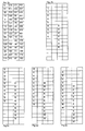
- An example of such a matrix structure is described in fig. 2a. Any distribution of threshold values between the minimum and maximum image density may be selected.
- the threshold values are arranged in a predetermined order. This order is such that with gradually increasing image density value a linear growth pattern of image dots of marking particles is generated parallel to the propagation direction of the image-carrying member by alternately adding image dots to both sides.
- a part of the digital image is selected having an area of the same size as a single matrix structure of the raster as in fig.2a, where 25% of the selected part contains black and 10% magenta.
- Black precedes magenta in the printing sequence and is the first process colour to be printed. Therefore no correction for an overlap is to be applied to the image signal associated with the black separation image.
- the image signal associated with the black separation image is binary halftoned using the threshold matrix structure of fig. 2a. In the resulting printing signal the cells indicating K will render image dots of black marking particles. Magenta however is preceded by black. Therefore preferably the image signal associated with the magenta separation image is corrected in order to create an overlap between both images.
- the correction may be such that the magenta separation image completely overlaps the black separation image. This is done on pixel level by adding the 8-bit image density values of the black colour to the corresponding 8-bit image density values of the magenta colour.
- the corrected magenta image signal is halftoned using the same matrix structure (fig. 2a). This is done such that with gradually increasing image density value of the magenta colour a linear growth pattern of image dots of magenta marking particles is generated parallel to the propagation direction of the image-carrying member by alternately adding magenta image dots to both sides.
- the resulting printing signal is depicted in fig 2c. As can be seen, as a result of the correction the coverage of the magenta separation image, when rendered separately, would be 35%.
- the multi-colour image as depicted in fig. 2d is formed on the image-carrying member yielding a 10% magenta marking particles coverage.
- a register error in the direction parallel to the propagation direction of the image-carrying member would result in a shift of one pixel of the magenta separation image with respect to the black separation image, then as can be seen in fig. 2e this would hardly effect the image quality as there is no change in the amount of magenta marking particles formed on the image-carrying member.
Priority Applications (4)
| Application Number | Priority Date | Filing Date | Title |
|---|---|---|---|
| EP02077308A EP1370066A1 (de) | 2002-06-05 | 2002-06-05 | Verfahren und System zur Verarbeitung eines mehrfarbigen Bildes |
| JP2003146148A JP4138576B2 (ja) | 2002-06-05 | 2003-05-23 | 多色画像を処理するための方法及びシステム |
| EP03076694.3A EP1370067B1 (de) | 2002-06-05 | 2003-06-02 | Verfahren und System zur Verarbeitung eines mehrfarbigen Bildes |
| US10/454,695 US7385731B2 (en) | 2002-06-05 | 2003-06-05 | Method and system for processing a multi-colour image |
Applications Claiming Priority (1)
| Application Number | Priority Date | Filing Date | Title |
|---|---|---|---|
| EP02077308A EP1370066A1 (de) | 2002-06-05 | 2002-06-05 | Verfahren und System zur Verarbeitung eines mehrfarbigen Bildes |
Publications (1)
| Publication Number | Publication Date |
|---|---|
| EP1370066A1 true EP1370066A1 (de) | 2003-12-10 |
Family
ID=29433181
Family Applications (1)
| Application Number | Title | Priority Date | Filing Date |
|---|---|---|---|
| EP02077308A Withdrawn EP1370066A1 (de) | 2002-06-05 | 2002-06-05 | Verfahren und System zur Verarbeitung eines mehrfarbigen Bildes |
Country Status (3)
| Country | Link |
|---|---|
| US (1) | US7385731B2 (de) |
| EP (1) | EP1370066A1 (de) |
| JP (1) | JP4138576B2 (de) |
Families Citing this family (5)
| Publication number | Priority date | Publication date | Assignee | Title |
|---|---|---|---|---|
| JP2000253215A (ja) * | 1999-03-02 | 2000-09-14 | Matsushita Electric Ind Co Ltd | 画像処理装置 |
| US7990573B2 (en) * | 2004-03-17 | 2011-08-02 | Xerox Corporation | User-adjustable mechanism for extracting full color information from two-color ink definitions |
| JP4825781B2 (ja) * | 2007-11-22 | 2011-11-30 | 株式会社 C−Mix | モーション生成装置およびコンピュータプログラム |
| EP2664129A1 (de) * | 2011-01-12 | 2013-11-20 | OCE-Technologies B.V. | Verfahren für halbkorrelierte rasterung |
| JP6335013B2 (ja) * | 2014-04-30 | 2018-05-30 | キヤノン株式会社 | 画像形成装置 |
Citations (7)
| Publication number | Priority date | Publication date | Assignee | Title |
|---|---|---|---|---|
| EP0370271A2 (de) * | 1988-11-24 | 1990-05-30 | Dainippon Screen Mfg. Co., Ltd. | Methode und Vorrichtung zum Aufzeichnen von Halbtonbildern und die dadurch hergestellten Halbtonbilder |
| EP0373704A1 (de) * | 1988-12-15 | 1990-06-20 | Océ-Nederland B.V. | Verfahren und Gerät zur Herstellung eines mehrfarbigen Bildes |
| WO1990010991A1 (en) * | 1989-03-07 | 1990-09-20 | The Color Group | Method and apparatus for producing half-tone separations in color imaging |
| WO1993022871A1 (en) * | 1992-05-06 | 1993-11-11 | Microsoft Corporation | Method and system of color halftone reproduction |
| EP0637886A2 (de) * | 1993-08-05 | 1995-02-08 | Xerox Corporation | Verfahren zur Vorbereitung eines Farbbildes |
| US5404156A (en) * | 1992-07-25 | 1995-04-04 | Fuji Xerox Co., Ltd. | Method and apparatus for forming a full-color image |
| US6172767B1 (en) * | 1996-11-15 | 2001-01-09 | Minolta Co., Ltd. | Multi-color image forming apparatus and multi-color image forming method |
Family Cites Families (6)
| Publication number | Priority date | Publication date | Assignee | Title |
|---|---|---|---|---|
| DE3787870T2 (de) * | 1986-11-20 | 1994-02-17 | Konishiroku Photo Ind | Farbabbildungsgerät. |
| US5708514A (en) * | 1994-08-31 | 1998-01-13 | Kabushiki Kaisha Toshiba | Error diffusion method in a multi-level image recording apparatus utilizing adjacent-pixel characteristics |
| US5751920A (en) * | 1995-01-26 | 1998-05-12 | Apple Computer, Inc. | System and method for adapting the thresholds of a dither matrix to the amplitude of an input signal |
| US6166828A (en) * | 1997-07-28 | 2000-12-26 | Canon Kabushiki Kaisha | Clearing ink jet nozzles during printing |
| WO2001058134A2 (en) * | 2000-02-01 | 2001-08-09 | Pictologic, Inc. | Method and apparatus for quantizing a color image through a single dither matrix |
| US6352806B1 (en) * | 2000-10-03 | 2002-03-05 | Xerox Corporation | Low toner pile height color image reproduction machine |
-
2002
- 2002-06-05 EP EP02077308A patent/EP1370066A1/de not_active Withdrawn
-
2003
- 2003-05-23 JP JP2003146148A patent/JP4138576B2/ja not_active Expired - Fee Related
- 2003-06-05 US US10/454,695 patent/US7385731B2/en not_active Expired - Fee Related
Patent Citations (7)
| Publication number | Priority date | Publication date | Assignee | Title |
|---|---|---|---|---|
| EP0370271A2 (de) * | 1988-11-24 | 1990-05-30 | Dainippon Screen Mfg. Co., Ltd. | Methode und Vorrichtung zum Aufzeichnen von Halbtonbildern und die dadurch hergestellten Halbtonbilder |
| EP0373704A1 (de) * | 1988-12-15 | 1990-06-20 | Océ-Nederland B.V. | Verfahren und Gerät zur Herstellung eines mehrfarbigen Bildes |
| WO1990010991A1 (en) * | 1989-03-07 | 1990-09-20 | The Color Group | Method and apparatus for producing half-tone separations in color imaging |
| WO1993022871A1 (en) * | 1992-05-06 | 1993-11-11 | Microsoft Corporation | Method and system of color halftone reproduction |
| US5404156A (en) * | 1992-07-25 | 1995-04-04 | Fuji Xerox Co., Ltd. | Method and apparatus for forming a full-color image |
| EP0637886A2 (de) * | 1993-08-05 | 1995-02-08 | Xerox Corporation | Verfahren zur Vorbereitung eines Farbbildes |
| US6172767B1 (en) * | 1996-11-15 | 2001-01-09 | Minolta Co., Ltd. | Multi-color image forming apparatus and multi-color image forming method |
Also Published As
| Publication number | Publication date |
|---|---|
| JP4138576B2 (ja) | 2008-08-27 |
| US7385731B2 (en) | 2008-06-10 |
| US20030227638A1 (en) | 2003-12-11 |
| JP2004104758A (ja) | 2004-04-02 |
Similar Documents
| Publication | Publication Date | Title |
|---|---|---|
| US5696594A (en) | Image forming method and apparatus for counterfeit protection controlling image synthesis in response to forming conditions | |
| EP2031857B1 (de) | Bildverarbeitungsvorrichtung und verfahren zur Steuerung der Menge an transparenter Tinte zur aufzeichnung | |
| JP4679575B2 (ja) | 単色画像データを表す複合画像データを生成する装置 | |
| US7058196B2 (en) | Apparatus and method for processing image and computer-readable storage medium | |
| US20090141311A1 (en) | Method and apparatus for multi-color printing using hybrid dot-line halftone composite screens | |
| US8724173B2 (en) | Control apparatus, controlling method, program and recording medium | |
| US7321447B2 (en) | System and method for processing a multi-colour image | |
| US7508557B2 (en) | System and method for processing a multi-colour image | |
| EP1370066A1 (de) | Verfahren und System zur Verarbeitung eines mehrfarbigen Bildes | |
| EP1370067B1 (de) | Verfahren und System zur Verarbeitung eines mehrfarbigen Bildes | |
| JP3375992B2 (ja) | 画像処理装置およびその方法 | |
| US7529005B2 (en) | Method for processing a multi-colour image | |
| EP1443748B1 (de) | System und Verfahren zur Verarbeitung eines mehrfarbigen Bildes | |
| EP1571827B1 (de) | Verfahren für die Verarbeitung eines mehrfarbigen Bildes | |
| EP1571828B1 (de) | Vorrichtung und Verfahren zur Verarbeitung eines mehrfarbigen Bildes | |
| JP4396112B2 (ja) | 画像形成装置およびその制御方法 | |
| JP3293844B2 (ja) | 画像処理装置およびその方法 | |
| JP2615271B2 (ja) | 階調処理方法 | |
| JP2010288143A (ja) | 画像処理装置 | |
| JPH1013684A (ja) | 印画装置 |
Legal Events
| Date | Code | Title | Description |
|---|---|---|---|
| PUAI | Public reference made under article 153(3) epc to a published international application that has entered the european phase |
Free format text: ORIGINAL CODE: 0009012 |
|
| STAA | Information on the status of an ep patent application or granted ep patent |
Free format text: STATUS: THE APPLICATION HAS BEEN WITHDRAWN |
|
| AK | Designated contracting states |
Kind code of ref document: A1 Designated state(s): AT BE CH CY DE DK ES FI FR GB GR IE IT LI LU MC NL PT SE TR |
|
| AX | Request for extension of the european patent |
Extension state: AL LT LV MK RO SI |
|
| 18W | Application withdrawn |
Effective date: 20031104 |