EP1369950A2 - Pile à combustible de type PEM et méthode de remplacement de l'Assemblage Membrane-Electrode (MEA) dans une pile à combustible de type PEM - Google Patents
Pile à combustible de type PEM et méthode de remplacement de l'Assemblage Membrane-Electrode (MEA) dans une pile à combustible de type PEM Download PDFInfo
- Publication number
- EP1369950A2 EP1369950A2 EP03001288A EP03001288A EP1369950A2 EP 1369950 A2 EP1369950 A2 EP 1369950A2 EP 03001288 A EP03001288 A EP 03001288A EP 03001288 A EP03001288 A EP 03001288A EP 1369950 A2 EP1369950 A2 EP 1369950A2
- Authority
- EP
- European Patent Office
- Prior art keywords
- pem fuel
- fuel cell
- bipolar plate
- damaged
- bipolar
- Prior art date
- Legal status (The legal status is an assumption and is not a legal conclusion. Google has not performed a legal analysis and makes no representation as to the accuracy of the status listed.)
- Withdrawn
Links
Images


Classifications
-
- H—ELECTRICITY
- H01—ELECTRIC ELEMENTS
- H01M—PROCESSES OR MEANS, e.g. BATTERIES, FOR THE DIRECT CONVERSION OF CHEMICAL ENERGY INTO ELECTRICAL ENERGY
- H01M8/00—Fuel cells; Manufacture thereof
- H01M8/02—Details
- H01M8/0202—Collectors; Separators, e.g. bipolar separators; Interconnectors
- H01M8/0247—Collectors; Separators, e.g. bipolar separators; Interconnectors characterised by the form
-
- H—ELECTRICITY
- H01—ELECTRIC ELEMENTS
- H01M—PROCESSES OR MEANS, e.g. BATTERIES, FOR THE DIRECT CONVERSION OF CHEMICAL ENERGY INTO ELECTRICAL ENERGY
- H01M8/00—Fuel cells; Manufacture thereof
- H01M8/24—Grouping of fuel cells, e.g. stacking of fuel cells
- H01M8/2465—Details of groupings of fuel cells
- H01M8/247—Arrangements for tightening a stack, for accommodation of a stack in a tank or for assembling different tanks
-
- H—ELECTRICITY
- H01—ELECTRIC ELEMENTS
- H01M—PROCESSES OR MEANS, e.g. BATTERIES, FOR THE DIRECT CONVERSION OF CHEMICAL ENERGY INTO ELECTRICAL ENERGY
- H01M8/00—Fuel cells; Manufacture thereof
- H01M8/02—Details
- H01M8/0202—Collectors; Separators, e.g. bipolar separators; Interconnectors
- H01M8/0204—Non-porous and characterised by the material
- H01M8/0206—Metals or alloys
-
- H—ELECTRICITY
- H01—ELECTRIC ELEMENTS
- H01M—PROCESSES OR MEANS, e.g. BATTERIES, FOR THE DIRECT CONVERSION OF CHEMICAL ENERGY INTO ELECTRICAL ENERGY
- H01M8/00—Fuel cells; Manufacture thereof
- H01M8/02—Details
- H01M8/0271—Sealing or supporting means around electrodes, matrices or membranes
-
- Y—GENERAL TAGGING OF NEW TECHNOLOGICAL DEVELOPMENTS; GENERAL TAGGING OF CROSS-SECTIONAL TECHNOLOGIES SPANNING OVER SEVERAL SECTIONS OF THE IPC; TECHNICAL SUBJECTS COVERED BY FORMER USPC CROSS-REFERENCE ART COLLECTIONS [XRACs] AND DIGESTS
- Y02—TECHNOLOGIES OR APPLICATIONS FOR MITIGATION OR ADAPTATION AGAINST CLIMATE CHANGE
- Y02E—REDUCTION OF GREENHOUSE GAS [GHG] EMISSIONS, RELATED TO ENERGY GENERATION, TRANSMISSION OR DISTRIBUTION
- Y02E60/00—Enabling technologies; Technologies with a potential or indirect contribution to GHG emissions mitigation
- Y02E60/30—Hydrogen technology
- Y02E60/50—Fuel cells
Definitions
- the invention relates generally to Proton-Exchange Membrane (“PEM”) fuel cells, more particularly, to a bipolar plate with keys employed in a PEM fuel cell, to a method of expediently and safely disassembling, repairing or replacing damaged Membrane Electrode Assembly (“MEA”) through the use of foregoing keys included in the bipolar plate, and to a procedure of simplifying the MEA re-assembling process.
- PEM Proton-Exchange Membrane
- MEA Membrane Electrode Assembly
- a PEM fuel cell is composed of a plurality of cell units, with each cell unit having bipolar plates, MEAs and gaskets.
- PEM fuel cell The type of membrane employed in such PEM fuel cell is polymer membrane, e.g., and, with the Nafion membrane as the electrolyte and platinum as the catalyst, electricity is generated through chemical reactions between hydrogen and oxygen/air.
- PEM fuel cells can be utilized either in households or in automobiles, for the operational temperature thereof is near 80° C. Certain smaller PEM fuel cells can even be utilized in portable equipment.
- the PEM fuel cell is considered a clean energy source, for the means of generating electricity thereby is through chemical reactions between hydrogen and oxygen/air, and the only waste material discharged during such process is water and heat, without producing any chemical or physical waste that might cause environmental or biological concerns and would require higher costs and complicated processing procedures, as would other types of energy-generating sources.
- the only noise generated during the operation of the PEM fuel cell is by fans in the system, a problem that is easy to solve, e.g., no noise shall be produced, provided pressurized air tanks are utilized in PEM fuel cells.
- the structure of a conventional PEM fuel cell 7, shown in Fig. 13 through 15, comprises a plurality of rectangular (e.g., square) bipolar plates 74 having identical sizes, a pair of current collectors 72 and 73, and a pair of end plates 70 and 71.
- a pair of piercing holes 28 is co-axially installed respectively on each foregoing bipolar plates 74 (please refer to Fig. 16) wherethrough a pair of guiding rods 60 is to pierce, such that the bipolar plates 74 are vertically stacked.
- the guiding rods 60 are utilized for guiding the plurality of bipolar plates 74 so as to expedite the assembling process of the bipolar plates 74.
- pair of guiding rods 60 pierces through the piercing holes 58 of the pair of end plates 70 and 71 respectively with the ends thereof protruding out of the surfaces of the end plates 70 and 71.
- the two outer sides of the stacked plurality of bipolar plates 74 are respectively installed with current collectors 72 and 73 utilized as positive and negative electrodes, with the two end plates 70 and 71 installed on the outer sides of the current collectors 72 and 73.
- the plurality of bipolar plates 74 and the current collectors 72 and 73 By evenly distributing the locations of the plurality of screw rods 16 on the periphery of the plurality of bipolar plates 74 and the current collectors 72 and 73 to pierce therethrough between the end plates 70 and 71, along with screw nuts 17 being fastened respectively on the protruding ends of the screw rods 16, the plurality of bipolar plates 74, the current collectors 72 and 73 and the metal end plate 70 and 71 are integrally compressed and locked, as shown in Fig. 13.
- the evenly distributed screw rods 16 assure the balance of pressure.
- the piercing hole 57A of the end plate 70 is installed with a hydrogen inlet 18A, whereas the piercing hole 57B is installed with an oxygen/air inlet 18B;
- the piercing hole 157A (corresponding to the foregoing piercing hole 57A on the other side) of the other end plate 71 is installed with a hydrogen outlet 19A, whereas the piercing hole 157B is installed with an oxygen/air outlet 19B.
- S-shaped grooves 743 are installed on the surfaces of the left side 741 and right side 742 for each bipolar plate 74 so as to channel gases, and all bipolar plates 74 are co-axially installed with the piercing holes 57A so as to channel hydrogen, whereas the piercing holes 57B are utilized for channeling oxygen/air (please refer to Fig. 16 to 18).
- hydrogen is channeled in through the hydrogen inlet 18A of the end plate 70, flowing through the piercing holes 57A and the corresponding gas channel 743 of the bipolar plates 74 and eventually discharged through the hydrogen outlet 19A.
- the PEM fuel cell 7 also includes a plurality of MEAs which are composite components with each of which having two carbon electrodes pressing on each side of the PEM. As shown in Fig. 16 to 18, each of these MEAs 45 is interposed between two bipolar plates 74. Further, in order to avoid gas leaking or any mixture of hydrogen and oxygen/air thus causing ill operation of the PEM fuel cell, gaskets 41 are interposed between each MEA 45 and each bipolar plate 74, so as to assure normal operation of the PEM fuel cell.
- the S-shaped groove 743 is installed on one side surface for each bipolar plate 74 (the left side surface 741) utilized for channeling hydrogen, as shown in Fig.
- Fig. 16 shows the structural diagram of the single MEA 45 and the adjacent bipolar plates 74 and 74.
- the MEAs 45 and the bipolar plates 74 in each cell are all conductive material, with all electric currents in such cell being connected and collected by the current collectors 72 and 73.
- the number and area for the bipolar plates 74 in the fuel cell 7 determines the number of Watt output. It is not necessary to go in detail here, for the structure and operational function of the conventional PEM fuel cell have already become extensively known to the public.
- each screw nut 17 on either side of the end plates 70 and 71 needs to be disassembled, thus re-forming the assembled state of the cell to be under the loosening state without being locked, and then both end plates 70 and 71 and both current collectors 72 and 73 are further separated, and then the bipolar plates 74, the MEAs 45 and the gaskets 41 are respectively pulled out from the guiding rods 60, until the dysfunctional MEAs are reached and separated.
- the foregoing USP No. 6,190,793 provides a compression assembly and an elongated tension member, so that the fastening and compressing stacks of bipolar plates can be strengthened, a design that fails to improve upon the drawback of complicated disassembling and re-assembling processes for replacing damaged MEAs in fuel cells.
- the foregoing USP No. 6,207,312 then provides a new internal gas-channel design for PEM fuel cells, a design that also fails to improve upon the drawback of complicated disassembling and re-assembling processes for replacing damaged MEAs in fuel cells.
- the installment of current collectors is then optional; which is to say, the current collectors are then not necessary for PEM fuel cells having end plates made of metal.
- the installment of current collectors then becomes mandatory.
- the primary object of the invention is to provide a bipolar plate having keys, and such bipolar plate, installed on two sides with at least one key having at least one piercing hole, is a unit for the whole Bipolar Plate Assembly ("BPA").
- BPA Bipolar Plate Assembly
- a further object of the invention is to provide a PEM fuel cell having a plurality of BPAs, with each of the BPA comprising bipolar plates having keys, MEAs and gaskets.
- Each bipolar plate has at least two sides installed with at least one key, on which at least one piercing hole is installed.
- the keys of the other BPAs enable the screw rods to lock sectionally, thus the BPAs containing the damaged MEAs can be separated, and the damaged MEAs replaced.
- Another object of the invention is to provide a method for replacing damaged MEAs in PEM fuel cells. Provided any damaged MEA needs to be replaced, certain amount of pressure is applied, under the means of sectional locking, upon the BPAs adjacent to the BPA containing the damaged MEA, so as to hold still the BPAs that do not contain the damaged MEAs; therefore, the bipolar plates, MEAs and gaskets in good condition are kept in their original places with no need to be moved, and only the BPA containing the damaged MEAs is separated so that the damaged MEAs are replaced, a design that significantly shortens the time needed to disassemble and re-assemble the conventional fuel cell, avoid the serious consequences of hydrogen leakage due to erroneous re-assembling processes, and prevent expensive MEAs in good condition from being damaged due to accidental percussions during the disassembling and re-assembling processes.
- the keys installed on bipolar plates do not adversely affect the function of fuel cells in any way, the keys further provide heat-dispersing function for fuel cells like cooling fins, which increase heat exchange during the operation of fuel cells, thus heat is released out to the surrounding atmosphere, a function that serves to keep the internal temperature of fuel cells under the range of operationability.
- the foregoing method for replacing damaged MEAs in PEM fuel cells saves more replacing time provided the number of BPAs increases.
- the foregoing method for replacing bipolar plates in PEM fuel cells provides the end users on-site maintenance service with no need to bring the whole fuel cell back to the manufacturing factories for maintenance.
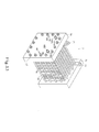
- the first embodiment of the PEM fuel cell 1 of the invention is shown in Fig. 1, comprising end plates 10 and 11, current collectors 12 and 13, the first BPA 21, the second BPA 22, the third BPA 23, the fourth BPA 24, the fifth BPA 25, the sixth BPA 26, a plurality of screw rods 16, a plurality of screw nuts 17, and a pair of guiding rods 60.
- the end plates 10 and 11, both designed as symmetrical structure, can be made of either metal or non-metal material; in this embodiment, the end plates 10 and 11 are designed to have sixteen piercing holes proportionally distributed thereon for being threaded through by sixteen screw rods 16, and a pair of piercing holes 58 for being threaded through by the guiding rods 60.
- the piercing hole 57A installed on the end plate 10 is fastened with the hydrogen inlet 18A by means of screws, whereas the piercing hole 57B is fastened with the oxygen/air inlet 18B by means of screws.
- the piercing holes 157A and 157B installed thereon are fastened respectively with the hydrogen outlet 19A and the oxygen/air outlet 19B, please refer to Fig. 2.
- the foregoing gas inlets 18A and 18B and the gas outlets 19A and 19B respectively have the identical functions to those of the gas inlets 18A and 18B and the gas outlets 19A and 19B of the conventional PEM fuel cell 7 shown in Fig. 13.
- the foregoing current collector 12 and 13 respectively have the identical functions to those of the current collectors 72 and 73 of the conventional PEM fuel cell 7 shown in Fig. 13.
- each of the BPAs 21, 22, 23, 24, 25 and 26 has four bipolar plates 14; however, for practical use, designers can alter the number of the BPAs in cells or the number of bipolar plates in BPAs.
- the MEAs, the gaskets and the grooves installed on surfaces of bipolar plates are omitted in this specification for better description. Still, the omitted members are necessary for embodying the invention.
- the guiding rods 60 are to thread through the piercing holes 28 co-axially installed respectively on the first BPA 21, the second BPA 22, the third BPA 23, the fourth BPA 24, the fifth BPA 25 and the sixth BPA 26 stacked together, thus threading each BPA together, and then the current collectors 12 and 13, end plates 10 and 11 are threaded in order on the outside of the threaded BPAs, thus the two ends of the guiding rods 60 are to protrude out of the end plates 10 and 11.
- the first BPA 21 has four bipolar plates 14 vertically aligned as shown in Fig. 3.
- the composition of the third and fifth BPAs 23 and 25 it is identical to that of the first BPA 21.
- the two keys 32 adjacent to one another on the same side of the bipolar plate 14 shown in Fig. 3 can be combined as a single key 32 as shown in Fig. 5.
- the second BPA 22 is similar to the first BPA 21, except that the keys 32 of the second BPA 22 are staggeredly installed without overlapping with the keys 32 of the first BPA 21.
- each screw rod 16 is to thread through the end plates 10 and 11 and every key 32 of each BPA, eventually the end plates 10 and 11, current collectors 12 and 13 and each BPA are compressed and locked together through fastening the screw nuts 17 on two protruding ends for each screw rod 16, as shown in Fig. 1.
- the PEM fuel cell 1 of the invention is to operate through reactions from the foregoing gases to produce water and electricity, a principle that is identical to that of the conventional fuel cell and thus it is no need to describe in detail here.
- the key 32 of the invention is utilized for the screw rods 16A and 16B having proper lengths to thread through, so as to lock the BPAs 21 and 23 to 26, thus separating the second BPA 22 containing the damaged MEA (as shown in Fig. 6) for replacement or repair. Therefore the damaged MEA can be replaced and the PEM fuel cell re-assembled easily and expediently, so that the proper operation of the PEM fuel cell can be maintained.
- the PEM fuel cell 1 shown in Fig. 7 is not identical to the first embodiment in that, the bipolar plate in Fig. 7 is the bipolar plate 14 shown in Fig. 4 and Fig. 5, and the keys of the bipolar plate are installed in both left-and-right directions, as well as up-and-down directions. According to Fig 7, numerous variations can be developed out of the invention.
- the third embodiment of the invention is further elaborated as follows.
- FIG. 8 Another type of PEM fuel cell 2 is shown in Fig. 8 in accordance with Fig. 9.
- Such type of PEM fuel cell 2 is not identical to the PEM fuel cell 1 in that, in the fuel cell 2 shown in Fig. 8, a plurality of screw rods 16 is to directly thread through the end plate 10, the first to sixth BPAs 21 to 26 (including MEAs and gaskets) and the end plate 11, and then the screw nuts 17 having the corresponding numbers are to lock the whole fuel cell 2 together. Since the metal screw rods 16 are to directly thread through the end plates 10 and 11 and each BPA, insulating material (not shown in figures) must be utilized to cover the exterior of the screw rods 16, so as to avoid short circuit. Furthermore, provided the end plates 10 and 11 are made of metal, screw holes 80 and 81 can be added respectively on one side of the end plates 10 and 11 for connecting the current output guide wire, thus no current collectors 12 and 13 are needed for such type of fuel cell 2.
- the PEM fuel cell 2 in Fig. 8 has guiding rods 60 that thread through the co-axial piercing holes 29 of the stacked first BPA 21, second BPA 22, third BPA 23, fourth BPA 24, fifth BPA 25, and sixth BPA 26 (shown in Fig. 10), thus threading each BPA together, and then the end plates 10 and 11 are threaded through in order, leaving the two ends of the guiding rods 60 protruding out of the end plates 10 and 11.
- Each screw rod 16 can then thread through the corresponding piercing holes installed on the end plates 10 and 11, and eventually the screw nuts 17 are fastened on the two ends for each screw rod 16, thus compressing and locking the end plates 10 and 11 and each BPA together.
- the key 32 of the invention is utilized for the screw rods 16C and 16D having proper lengths to thread through, so as to lock the BPAs 21 and 22 and 24 to 26, thus separating the third BPA 23 containing the damaged MEA (as shown in Fig. 10) for replacement or repair. Therefore the damaged MEA can be replaced and the PEM fuel cell re-assembled easily and expediently, so that the proper operation of the PEM fuel cell can be maintained.
- the number of bipolar plates in each BPA can be various according to different needs for the number of Watt output. As the number of bipolar plates in a BPA becomes larger, the pressure taken by the screw rods and screw nuts becomes greater, thus the BPAs are compressed further by higher pressure.
- the positions for keys installing on the bipolar plates are important in that, through the design of a plurality of keys, pressure is to be distributed to the whole bipolar plate without concentrating on areas adjacent to a single key. Therefore, the shape, size, installing position and number of a key on each bipolar plate can vary according to different needs.
- the bipolar plate 14 can further be hexagonal, with at least two outwardly extending keys 32 being installed thereon; such key is installed with at least one piercing hole 33.
- the bipolar plate 14 can further be octagonal, with at least two outwardly extending keys 32 being installed thereon; such key is installed with at least one piercing hole 33.
- the keys installed on bipolar plates do not adversely affect the function of fuel cells in any way, the keys further provide heat-dispersing function for fuel cells like cooling fins, which increase heat exchange during the operation of fuel cells, thus heat is to be released out to the surrounding atmosphere, thus serving to keep the internal temperature of fuel cells under the range of operationability.
- the foregoing method for replacing damaged MEAs in PEM fuel cells saves more replacing time provided the number of BPAs increases.
- the foregoing method for replacing bipolar plates in PEM fuel cells provides the end users on-site maintenance service with no need to bring the whole fuel cell back to the manufacturing factories for maintenance.
- end plates are not limited by the invention.
- current collectors can be installed, but not mandatory. when end plates are not made of metal, current collectors then become necessary members in such PEM fuel cell.
- It is also not limited by the invention as to the number of keys on bipolar plates or shapes of bipolar plates. It is no need to elaborate the order for detailed disassembling of the screw rods or screw nuts as long as the method of sectional locking is followed within the spirit and scope of the invention.
- the foregoing drawings and elaboration are not to be taken in a limiting sense, but are made merely for the purpose of illustrating the general principles of the invention.
Applications Claiming Priority (2)
| Application Number | Priority Date | Filing Date | Title |
|---|---|---|---|
| CN02120297A CN1459885A (zh) | 2002-05-16 | 2002-05-16 | Pem燃料电池及更换pem燃料电池薄膜电极组的方法 |
| CN02120297 | 2002-05-16 |
Publications (1)
| Publication Number | Publication Date |
|---|---|
| EP1369950A2 true EP1369950A2 (fr) | 2003-12-10 |
Family
ID=29427001
Family Applications (1)
| Application Number | Title | Priority Date | Filing Date |
|---|---|---|---|
| EP03001288A Withdrawn EP1369950A2 (fr) | 2002-05-16 | 2003-01-22 | Pile à combustible de type PEM et méthode de remplacement de l'Assemblage Membrane-Electrode (MEA) dans une pile à combustible de type PEM |
Country Status (2)
| Country | Link |
|---|---|
| EP (1) | EP1369950A2 (fr) |
| CN (1) | CN1459885A (fr) |
Cited By (4)
| Publication number | Priority date | Publication date | Assignee | Title |
|---|---|---|---|---|
| WO2007090819A1 (fr) * | 2006-02-06 | 2007-08-16 | Nuvera Fuel Cells Europe Srl | Empilement de piles a combustible |
| EP1933408A1 (fr) * | 2006-12-11 | 2008-06-18 | Staxera GmbH | Unité de répétition pour une pile de cellules de combustibles et plaque bipolaire destinée à une telle unité de répétition |
| CN115036548A (zh) * | 2022-06-02 | 2022-09-09 | 深圳市氢蓝时代动力科技有限公司 | 电池电堆返修设备 |
| US11611091B2 (en) | 2021-02-10 | 2023-03-21 | Cummins Inc. | Air tank and variable geometry air handling in hydrogen fuel cells |
Families Citing this family (10)
| Publication number | Priority date | Publication date | Assignee | Title |
|---|---|---|---|---|
| CN100414754C (zh) * | 2004-01-16 | 2008-08-27 | 上海神力科技有限公司 | 一种集成式燃料电池堆的封装与固定装置 |
| CN100464455C (zh) * | 2004-04-07 | 2009-02-25 | 上海神力科技有限公司 | 一种带有电压监控检测槽孔的燃料电池导流极板 |
| KR100637484B1 (ko) * | 2004-04-22 | 2006-10-20 | 삼성에스디아이 주식회사 | 연료 전지용 스택과 그 시스템 및 스택 제조방법 |
| CN1312801C (zh) * | 2004-07-21 | 2007-04-25 | 中国科学院大连化学物理研究所 | 一种质子交换膜燃料电池的组装结构 |
| CN100338804C (zh) * | 2004-11-26 | 2007-09-19 | 中国科学院大连化学物理研究所 | 带有假电池的质子交换膜燃料电池 |
| JP5134272B2 (ja) * | 2007-03-23 | 2013-01-30 | 本田技研工業株式会社 | 燃料電池スタック |
| CN101764240B (zh) * | 2008-12-26 | 2012-02-29 | 财团法人工业技术研究院 | 燃料电池组 |
| CN104538651B (zh) * | 2014-11-27 | 2017-02-22 | 同济大学 | 用于x射线吸收精细结构谱测试的质子交换膜燃料电池 |
| CN105098198B (zh) * | 2014-12-22 | 2018-07-24 | 武汉众宇动力系统科技有限公司 | 用于燃料电池的双极板 |
| CN112886043A (zh) * | 2019-11-29 | 2021-06-01 | 国家能源投资集团有限责任公司 | 电池堆端板及燃料电池堆及燃料电池堆堆塔 |
-
2002
- 2002-05-16 CN CN02120297A patent/CN1459885A/zh active Pending
-
2003
- 2003-01-22 EP EP03001288A patent/EP1369950A2/fr not_active Withdrawn
Cited By (7)
| Publication number | Priority date | Publication date | Assignee | Title |
|---|---|---|---|---|
| WO2007090819A1 (fr) * | 2006-02-06 | 2007-08-16 | Nuvera Fuel Cells Europe Srl | Empilement de piles a combustible |
| EP1933408A1 (fr) * | 2006-12-11 | 2008-06-18 | Staxera GmbH | Unité de répétition pour une pile de cellules de combustibles et plaque bipolaire destinée à une telle unité de répétition |
| WO2008071141A2 (fr) * | 2006-12-11 | 2008-06-19 | Staxera Gmbh | Unité de répétition pour un empilement de piles à combustible et plaque bipolaire pour une telle unité de répétition |
| WO2008071141A3 (fr) * | 2006-12-11 | 2008-08-14 | Staxera Gmbh | Unité de répétition pour un empilement de piles à combustible et plaque bipolaire pour une telle unité de répétition |
| US11611091B2 (en) | 2021-02-10 | 2023-03-21 | Cummins Inc. | Air tank and variable geometry air handling in hydrogen fuel cells |
| CN115036548A (zh) * | 2022-06-02 | 2022-09-09 | 深圳市氢蓝时代动力科技有限公司 | 电池电堆返修设备 |
| CN115036548B (zh) * | 2022-06-02 | 2023-09-08 | 深圳市氢蓝时代动力科技有限公司 | 电池电堆返修设备 |
Also Published As
| Publication number | Publication date |
|---|---|
| CN1459885A (zh) | 2003-12-03 |
Similar Documents
| Publication | Publication Date | Title |
|---|---|---|
| US6099984A (en) | Mirrored serpentine flow channels for fuel cell | |
| EP1109241B1 (fr) | Des canaux d'écoulement dans des plaques de collecteur de courant pour piles à combustible | |
| TW466792B (en) | Sheet metal bipolar plate design for polymer electrolyte membrane fuel cells | |
| US6720101B1 (en) | Solid cage fuel cell stack | |
| US6989214B2 (en) | Unitized fuel cell assembly | |
| EP1369950A2 (fr) | Pile à combustible de type PEM et méthode de remplacement de l'Assemblage Membrane-Electrode (MEA) dans une pile à combustible de type PEM | |
| US7482087B2 (en) | Fuel cell | |
| US8367270B2 (en) | Flow field plate arrangement for a fuel cell | |
| US6699614B2 (en) | Converging/diverging flow channels for fuel cell | |
| US8153316B2 (en) | Unitized fuel cell assembly and cooling apparatus | |
| EP1107339A2 (fr) | Des canaux d'écoulement dans des plaques de collecteur de courant pour piles à combustible | |
| US8012642B2 (en) | Power supply apparatus having plurality of planar fuel cell assemblies connected in stack form | |
| US20080241636A1 (en) | Sealed water vapor transfer unit assembly with integrated load transferring structure | |
| WO2009093622A1 (fr) | Collecteur de pile à combustible à oxyde solide et empilement correspondant | |
| US20030203265A1 (en) | PEM fuel cell and method for replacing MEA in PEM fuel cell | |
| US6926985B2 (en) | Fuel cell stack | |
| US6656621B2 (en) | Fuel cell stack | |
| US20070207358A1 (en) | Fuel Cell Stack and Related Method | |
| US7537854B2 (en) | Polymer electrolyte fuel cell and stack therefor, and method of manufacturing the same | |
| US11205786B2 (en) | Fuel cell having heating unit therefor | |
| KR101484859B1 (ko) | 내부 중앙을 관통하는 중공 내에 체결봉을 슬라이딩 타입으로 삽입하여 체결하는 엔드 플레이트를 구비한 공냉식 연료전지 | |
| KR20240053247A (ko) | 연료 전지 장치 | |
| KR20240002761A (ko) | 연료 전지 | |
| WO2005028711A1 (fr) | Joint d'etancheite pour pile electrochimique |
Legal Events
| Date | Code | Title | Description |
|---|---|---|---|
| PUAI | Public reference made under article 153(3) epc to a published international application that has entered the european phase |
Free format text: ORIGINAL CODE: 0009012 |
|
| 17P | Request for examination filed |
Effective date: 20030122 |
|
| AK | Designated contracting states |
Kind code of ref document: A2 Designated state(s): AT BE BG CH CY CZ DE DK EE ES FI FR GB GR HU IE IT LI LU MC NL PT SE SI SK TR |
|
| AX | Request for extension of the european patent |
Extension state: AL LT LV MK RO |
|
| STAA | Information on the status of an ep patent application or granted ep patent |
Free format text: STATUS: THE APPLICATION IS DEEMED TO BE WITHDRAWN |
|
| 18D | Application deemed to be withdrawn |
Effective date: 20050801 |