EP1369637A2 - Übergangsstück für eine Rohrauskleidung - Google Patents
Übergangsstück für eine Rohrauskleidung Download PDFInfo
- Publication number
- EP1369637A2 EP1369637A2 EP03253434A EP03253434A EP1369637A2 EP 1369637 A2 EP1369637 A2 EP 1369637A2 EP 03253434 A EP03253434 A EP 03253434A EP 03253434 A EP03253434 A EP 03253434A EP 1369637 A2 EP1369637 A2 EP 1369637A2
- Authority
- EP
- European Patent Office
- Prior art keywords
- insert
- liner
- pipe
- expandable
- prongs
- Prior art date
- Legal status (The legal status is an assumption and is not a legal conclusion. Google has not performed a legal analysis and makes no representation as to the accuracy of the status listed.)
- Granted
Links
Images


Classifications
-
- F—MECHANICAL ENGINEERING; LIGHTING; HEATING; WEAPONS; BLASTING
- F16—ENGINEERING ELEMENTS AND UNITS; GENERAL MEASURES FOR PRODUCING AND MAINTAINING EFFECTIVE FUNCTIONING OF MACHINES OR INSTALLATIONS; THERMAL INSULATION IN GENERAL
- F16L—PIPES; JOINTS OR FITTINGS FOR PIPES; SUPPORTS FOR PIPES, CABLES OR PROTECTIVE TUBING; MEANS FOR THERMAL INSULATION IN GENERAL
- F16L55/00—Devices or appurtenances for use in, or in connection with, pipes or pipe systems
- F16L55/16—Devices for covering leaks in pipes or hoses, e.g. hose-menders
- F16L55/162—Devices for covering leaks in pipes or hoses, e.g. hose-menders from inside the pipe
- F16L55/165—Devices for covering leaks in pipes or hoses, e.g. hose-menders from inside the pipe a pipe or flexible liner being inserted in the damaged section
-
- B—PERFORMING OPERATIONS; TRANSPORTING
- B25—HAND TOOLS; PORTABLE POWER-DRIVEN TOOLS; MANIPULATORS
- B25B—TOOLS OR BENCH DEVICES NOT OTHERWISE PROVIDED FOR, FOR FASTENING, CONNECTING, DISENGAGING OR HOLDING
- B25B27/00—Hand tools, specially adapted for fitting together or separating parts or objects whether or not involving some deformation, not otherwise provided for
- B25B27/02—Hand tools, specially adapted for fitting together or separating parts or objects whether or not involving some deformation, not otherwise provided for for connecting objects by press fit or detaching same
- B25B27/10—Hand tools, specially adapted for fitting together or separating parts or objects whether or not involving some deformation, not otherwise provided for for connecting objects by press fit or detaching same inserting fittings into hoses
-
- B—PERFORMING OPERATIONS; TRANSPORTING
- B25—HAND TOOLS; PORTABLE POWER-DRIVEN TOOLS; MANIPULATORS
- B25B—TOOLS OR BENCH DEVICES NOT OTHERWISE PROVIDED FOR, FOR FASTENING, CONNECTING, DISENGAGING OR HOLDING
- B25B27/00—Hand tools, specially adapted for fitting together or separating parts or objects whether or not involving some deformation, not otherwise provided for
- B25B27/14—Hand tools, specially adapted for fitting together or separating parts or objects whether or not involving some deformation, not otherwise provided for for assembling objects other than by press fit or detaching same
- B25B27/28—Hand tools, specially adapted for fitting together or separating parts or objects whether or not involving some deformation, not otherwise provided for for assembling objects other than by press fit or detaching same positioning or withdrawing resilient bushings or the like
-
- F—MECHANICAL ENGINEERING; LIGHTING; HEATING; WEAPONS; BLASTING
- F16—ENGINEERING ELEMENTS AND UNITS; GENERAL MEASURES FOR PRODUCING AND MAINTAINING EFFECTIVE FUNCTIONING OF MACHINES OR INSTALLATIONS; THERMAL INSULATION IN GENERAL
- F16L—PIPES; JOINTS OR FITTINGS FOR PIPES; SUPPORTS FOR PIPES, CABLES OR PROTECTIVE TUBING; MEANS FOR THERMAL INSULATION IN GENERAL
- F16L33/00—Arrangements for connecting hoses to rigid members; Rigid hose-connectors, i.e. single members engaging both hoses
- F16L33/22—Arrangements for connecting hoses to rigid members; Rigid hose-connectors, i.e. single members engaging both hoses with means not mentioned in the preceding groups for gripping the hose between inner and outer parts
- F16L33/223—Arrangements for connecting hoses to rigid members; Rigid hose-connectors, i.e. single members engaging both hoses with means not mentioned in the preceding groups for gripping the hose between inner and outer parts the sealing surfaces being pressed together by means of a member, e.g. a swivel nut, screwed on or into one of the joint parts
Definitions
- This invention relates to transition fittings, and more particularly to a transition fitting for an expandable pipe liner and to an insertion tool for introducing an insert into an expandable pipe liner.
- WO97/04269 As an alternative to complete replacement of lead pipes, it has been proposed in WO97/04269 to line the pipes with a polyethylene film which is everted by fluid pressure into the pipe.
- a polyethyleneterepthalate film is extruded as a profile, inserted in the pipe, inflated by fluid pressure and heated in situ. This presses the lining against the inner walls of the pipe and softens the lining to promote thermal bonding to the pipe wall.
- a tubular liner within a pipe, characterised in that the liner comprises a polyolefin elastomer or a polyolefin plastomer.
- a polyolefin elastomer has a specific gravity below 870 kg/m 3
- a polyolefin plastomer has a specific gravity above 870 kg/m 3 .
- the polyethylene elastomer/plastomer generally comprises a substantially linear ethylene interpolymer, which may comprise 50 to 95% by weight of ethylene, and 5 to 50% by weight of at least one olefinic comonomer, preferably 10 to 25% by weight of the comonomer.
- Comonomers may contain from 3 to about 20 carbon atoms, and may comprise one or more of propylene, 1-butene, 1-hexene, 4-methyl-1-pentene, 1-heptene, and 1-octene.
- the specific gravity may be in the range of 830 to 967 kg/m 3 , preferably 863 to 913 kg/m 3 and more preferably 885 to 913 kg/m 3 , for optimum toughness and flexibility.
- Preferred comonomers are 1-hexene and especially 1-octene.
- the substantially linear inter polymers are advantageously characterised by a narrow molecular weight distribution, especially from 1.8 to 2.2, and a homogenous comonomer distribution.
- the tubular liner is formed as a pleated tube with longitudinally extending multiple radial pleats, giving a star shaped, multi-lobed, or fluted cross-section.
- the tube is formed with six radially equispaced pleats, defining an equal number of outwardly projecting lobes.
- the liner may be deployed within a pipe, by securing one end of the liner adjacent an end of the pipe to which access has been obtained, and pulling the liner through the pipe by means of a cable attached to a foam messenger pig which is propelled through the pipe by fluid pressure. Alternatively, the liner may be pushed and pulled through the host pipe by means of a flexible rod attached to the liner.
- Preferred embodiments of the liner and the method of insertion of the liner into a pipe are disclosed in the body of the specification of WO00/63605.
- the wall thickness is from 0.25 to 0.55 mm.
- Such a liner is intended for the rehabilitation of an old lead pipe whose internal diameter is in the range of 10 to 20 mm.
- the water supply is reconnected to the pipe.
- the liner is expanded, by the pressure head in the water supplied through the pipe, into a roughly circular shape, and is then stretched in an elastic manner until it comes into contact with the inside surface of the lead pipe wall.
- the invention provides a transition fitting for an expandable pipe liner which comprises:
- the invention provides a transition fitting for a pipe, the pipe having an expandable liner disposed therein, which liner has an unsupported length extending from an end of the pipe, the fitting comprising:
- the invention provides an insertion tool for introducing an insert into an expandable pipe liner which comprises:
- the tubular body of the second aspect of the invention is secured to the expandable liner by means of the tapered insert, collar and compression cap of the first aspect of the invention.
- a method for introducing an insert into an expandable pipe liner in which there is used an insertion tool, the tool comprising an array of outwardly deflectable elongate prongs arranged in a conical array and adapted to expand an expandable pipe liner positioned thereover and an insert carrier adapted to receive an insert thereon, the insert being axially disposed within the conical array of prongs and axially moveable with respect thereto, the method comprising disposing an annular insert on the insert carrier, positioning an expandable pipe liner over the conical array of prongs, moving the insert carrier and insert towards the apex of the conical array of prongs such that the prongs are forced apart, expanding the expandable liner, forwarding the insert and insert carrier through the conical array of prongs such that the insert is positioned in the expanded pipe liner, and withdrawing the insert carrier leaving the insert positioned in the expandable pipe liner.
- the insert preferably has an external tapered face which has the same taper angle as the internal tapered face of the collar. Both components are preferably machined from brass, or another suitable metallic material, or injection moulded from a suitable engineering plastics material.
- the tubular body has two opposed orifices in the tubular wall thereof and the liner support means comprises interlocking profiles which can be inserted through the orifices and joined to form a cylindrical support for the unsupported length of expandable liner.
- the means for securing the fitting to the pipe comprises one or more taper lock plugs disposed within the tubular body of the fitting.
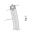
- Figures 1 shows a pipe liner suitable for use with the transition fitting and method of the present invention.
- the liner illustrated generally at 1, has a star-shaped profile with 6 symmetrically-arranged lobes 2. This liner is used to reline a lead pipe 3 of nominal bore in the range of 12.5 to 13.0 mm.
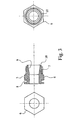
- FIG. 2 there is shown the liner 1 inserted in a lead pipe 3 and protruding a short distance from an end thereof.
- a transition fitting body component 4 is slidable over the end of the lead pipe 3 and is connected to a brass collar 5.
- the brass collar has a hexagonal section 6 and a screw threaded end section 7 which protrude from the fitting body 4.
- An internal circular lip 39 (see Figure 16) on the body component 4 fits into a circular recess 8 on the brass collar 5 in order to make a firm connection therewith.
- the brass collar has a bore with a tapered internal section 9 which extends from an end face 10 of the collar.
- An annular tapered brass insert 11 is shown in Figure 4.
- the insert 11 has a tapered outer face 12, which has the same taper angle as the tapered internal bore section 9 of the collar 5.
- An objective of the transition fitting is to fit the brass insert 11 inside the liner 1 and then to trap the liner between the insert and the inside tapered bore section 9 of the collar 5.
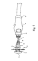
- the invention provides a tool, which is depicted in Figures 5 to 13.
- the insertion tool illustrated generally at 13, comprises a shaft 14 having at its remote end a pressure pad 15, and at its near end an insert carrier 16.
- an insert 11 is shown mounted on the insert carrier 16.
- a carriage 17, slidably mounted upon the shaft 14, comprises a circular plate 18 upon which are pivotally mounted three elongate prongs 19, in a generally cone-shaped configuration.
- the tips 20 of the prongs 19 are urged together by a rubber ring 21 which extends around the base of the prongs 19.
- the tips 20 of the prongs 19 are profiled and have serrations 22 in order to receive and grip an end of the liner 1.
- the length of liner protruding from the lead pipe 3 is pinched between the fingers of the installer to prevent it sliding and the tips 20 of the prongs 19 are inserted into the exposed end of the liner.
- transition fitting body component 4 and brass collar 5 are slid axially along the lead pipe 3 until the insert 11 can be mated with the brass collar 5.
- an internally threaded compression cap 22 has been screwed onto the external thread 6 of the collar 5 to apply axial pressure upon the insert 11, forcing it into the tapered bore 9 of the collar 5 and increasing the compression on the wall of the liner 1.
- a sealing ring 23 is placed over the collar and is seated between the hexagonal section 5 of the collar and a corresponding hexagonal section 24 on the compression cap 22.
- the compression cap 22 is shown in more detail in Figure 11, where it can be seen to have an internally threaded section 25, which co-operates with the externally threaded section 6 of the collar 5, and a thrust face 26 which presses against the insert 11.
- the compression cap has an internal tapered section 27 which cooperates with the taper of the insert 11 to make a smooth flow channel through the fitting.
- An external thread 28 on the compression cap 22 permits the transition fitting to be connected to other components.
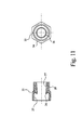
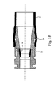
- Figure 13 shows a second design in which the threaded section 28 on the compression cap 22 of Figure 12 is replaced by a ribbed, profiled section 29 on the second compression cap 30. Components using this ribbed, profiled design are sold by Uponor Oy under the Trade Mark Quick & Easy.
- the assembly of the Quick & Easy system is shown in Figure 14.
- a cross-linked polyethylene sleeve 31 is placed over an end of a polyethylene pipe 32 to be connected to the compression cap 30.
- An expansion tool 33 is then used to expand the cross-linked polyethylene sleeve 31 and the end of the polyethylene pipe 32 sufficiently to allow the insertion into the pipe 32 of the profiled section 29 of the compression cap 30.
- FIG. 15 shows the second compression cap 30 inserted into the polyethylene pipe 32, with the outer cross-linked polyethylene sleeve 31 omitted.
- Figure 16 shows one half-shell of the moulded fitting body 4, showing the position of the sliding taper lock plug 34.
- Two taper lock plugs 34 are provided, of which only one is shown.
- the taper lock plugs run in channels 35, which are provided with a ratchet detail 36.
- Each half-shell of the body 4 is provided with a press fit locking hook 37 which engages in a corresponding recess 38 on the other half-shell.
- Circular lips 39 engage with the annular recess 8 in the collar 4.
- Also illustrated in Figure 16 is one of two liner support insert members 40, the function of which will be more particularly described hereinafter.
- the two half-shells of the body 4 are a press fit together and are held by metal circlips 41, 42 which slide over each end of the assembled body 4 as shown in Figure 17.
- the taper lock plugs have protruding integral buttons 43 which enable the taper lock plugs to be moved along the taper of the body 4, in the channels 35, to engage the lead pipe 3 (see Figure 3) forming a connection which resists axial pull-out forces.
- Apertures 48 are sized in order to allow for the axial displacement of the body component 4 and to accommodate the interlocking liner support members 40.
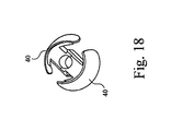
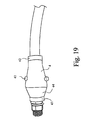
- the interlocking liner support insert members 40 are shown in Figures 18 to 20. Each insert member 40 has an external saddle-shaped portion 44 upon which is mounted a semi-circular liner support 45 on pillars 46. The liner support insert members 40 have extending hooks 47 which are a press fit against shoulders 47a. The assembled interlocked liner support inserts are shown in Figure 18.
- the liner support insert members 40 In installing the liner support insert members 40, they are each inserted into the apertures 48 and pressed together to lock them within the body component 4.
- the interlocked liner supports 45 encircle the unsupported liner and provide the required stability in use.
Landscapes
- Engineering & Computer Science (AREA)
- General Engineering & Computer Science (AREA)
- Mechanical Engineering (AREA)
- Lining Or Joining Of Plastics Or The Like (AREA)
- Dowels (AREA)
- Mechanical Coupling Of Light Guides (AREA)
- Quick-Acting Or Multi-Walled Pipe Joints (AREA)
- Rigid Pipes And Flexible Pipes (AREA)
- Laminated Bodies (AREA)
- Protection Of Pipes Against Damage, Friction, And Corrosion (AREA)
- Joints That Cut Off Fluids, And Hose Joints (AREA)
Applications Claiming Priority (2)
| Application Number | Priority Date | Filing Date | Title |
|---|---|---|---|
| GB0212809A GB2389399B (en) | 2002-06-05 | 2002-06-05 | Transition fitting |
| GB0212809 | 2002-06-05 |
Publications (3)
| Publication Number | Publication Date |
|---|---|
| EP1369637A2 true EP1369637A2 (de) | 2003-12-10 |
| EP1369637A3 EP1369637A3 (de) | 2004-03-03 |
| EP1369637B1 EP1369637B1 (de) | 2005-12-14 |
Family
ID=9937941
Family Applications (1)
| Application Number | Title | Priority Date | Filing Date |
|---|---|---|---|
| EP03253434A Expired - Lifetime EP1369637B1 (de) | 2002-06-05 | 2003-05-31 | Übergangsstück für eine Rohrauskleidung |
Country Status (4)
| Country | Link |
|---|---|
| EP (1) | EP1369637B1 (de) |
| AT (1) | ATE313038T1 (de) |
| DE (1) | DE60302707D1 (de) |
| GB (1) | GB2389399B (de) |
Cited By (1)
| Publication number | Priority date | Publication date | Assignee | Title |
|---|---|---|---|---|
| CN103753949A (zh) * | 2013-12-31 | 2014-04-30 | 广州丽盈塑料有限公司 | 一种无头软管印刷的工装结构 |
Family Cites Families (13)
| Publication number | Priority date | Publication date | Assignee | Title |
|---|---|---|---|---|
| US550560A (en) * | 1895-11-26 | Tire-repairing tool | ||
| US2709606A (en) * | 1949-01-14 | 1955-05-31 | Mueller Co | Pipe coupling having perforated socket for solder |
| DE1223136B (de) * | 1962-10-31 | 1966-08-18 | Shell Int Research | Vorrichtung zum Aufbringen des Endteiles von dehnbaren Schlaeuchen auf einen Koerper, dessen Querschnitt in der Aufbringungsebene den Innen-querschnitt des Schlauches anGroesse ueberragt |
| GB2147243B (en) * | 1983-10-01 | 1986-10-15 | Standard Telephones Cables Ltd | Applying thermoplastics sleeve to crush resistant tubing |
| US4679826A (en) * | 1985-05-06 | 1987-07-14 | Flow Industries, Inc. | High pressure hose fitting |
| GB2263696B (en) * | 1989-09-22 | 1994-05-11 | British Gas Plc | Sealant |
| US5178423A (en) * | 1990-02-28 | 1993-01-12 | Alberto Combeau | Fast assembly for flexible pipings |
| JPH04146031A (ja) * | 1990-10-09 | 1992-05-20 | Bridgestone Corp | 筒状ゴムへの芯棒挿入方法及びその装置 |
| US5452921A (en) * | 1991-10-31 | 1995-09-26 | The Deutsch Company | Axially swaged fitting |
| NL9500454A (nl) * | 1995-03-07 | 1996-10-01 | Watson B V | Inrichting voor het koppelen van twee pijpen. |
| WO1998026207A1 (en) * | 1996-12-13 | 1998-06-18 | Polyline Technologies Limited | Lining pipes |
| NO972019L (no) * | 1997-04-30 | 1998-11-02 | Olimb As Kristian | Endeavslutning for r°r |
| GB9908602D0 (en) * | 1999-04-15 | 1999-06-09 | Northumbria Lyonnaise Technolo | Rehabilitation of water supply pipes |
-
2002
- 2002-06-05 GB GB0212809A patent/GB2389399B/en not_active Revoked
-
2003
- 2003-05-31 EP EP03253434A patent/EP1369637B1/de not_active Expired - Lifetime
- 2003-05-31 AT AT03253434T patent/ATE313038T1/de not_active IP Right Cessation
- 2003-05-31 DE DE60302707T patent/DE60302707D1/de not_active Expired - Lifetime
Cited By (2)
| Publication number | Priority date | Publication date | Assignee | Title |
|---|---|---|---|---|
| CN103753949A (zh) * | 2013-12-31 | 2014-04-30 | 广州丽盈塑料有限公司 | 一种无头软管印刷的工装结构 |
| CN103753949B (zh) * | 2013-12-31 | 2017-04-12 | 广州丽盈塑料有限公司 | 一种无头软管印刷的工装结构 |
Also Published As
| Publication number | Publication date |
|---|---|
| GB2389399A9 (en) | 2005-06-23 |
| EP1369637A3 (de) | 2004-03-03 |
| EP1369637B1 (de) | 2005-12-14 |
| GB0212809D0 (en) | 2002-07-10 |
| ATE313038T1 (de) | 2005-12-15 |
| DE60302707D1 (de) | 2006-01-19 |
| GB2389399A (en) | 2003-12-10 |
| GB2389399B (en) | 2006-01-11 |
Similar Documents
| Publication | Publication Date | Title |
|---|---|---|
| US6345431B1 (en) | Joining thermoplastic pipe to a coupling | |
| US7134204B2 (en) | Integral restraint system and method of manufacture for plastic pipe | |
| US8770630B2 (en) | Hose connecting method and connector arrangement | |
| FI101498B (fi) | Muhviliitos muoviputkia varten | |
| US5056833A (en) | Flexible pipe coupling | |
| US9080704B2 (en) | Universal pipe coupler | |
| US20110309616A1 (en) | Sanitary hose coupling | |
| US6832791B2 (en) | Connection means for interconnecting two duct elements | |
| JP2007500828A (ja) | 壁開口部中で拡張可能な管状の金属継手および設置の方法 | |
| US7163238B1 (en) | Connector for flexible and semi-rigid pipings | |
| US20040178630A1 (en) | Pipe coupling | |
| EP1369637B1 (de) | Übergangsstück für eine Rohrauskleidung | |
| WO1994001711A1 (en) | Fluid line connector fitting | |
| GB2225406A (en) | Methods and apparatus for use in pipe lining. | |
| US8709318B2 (en) | Method and apparatus for belling plastic pipe | |
| GB2416577A (en) | Transition fittings | |
| GB2416576A (en) | Transition fittings | |
| US5683116A (en) | O-ring push-pull pipe joint | |
| WO2007049053A1 (en) | Hose connector | |
| EP1800047B1 (de) | Rohrkupplung | |
| RU64318U1 (ru) | Узел соединения труб | |
| US20030034647A1 (en) | Removable pipe coupler | |
| GB2471502A (en) | A universal compression-type pipe coupling | |
| EP1927807A1 (de) | Schnell lösbare Kupplungsvorrichtung, insbesondere für Rohre und dergleichen | |
| US20070126231A1 (en) | Coupling with pull-out resistance |
Legal Events
| Date | Code | Title | Description |
|---|---|---|---|
| PUAI | Public reference made under article 153(3) epc to a published international application that has entered the european phase |
Free format text: ORIGINAL CODE: 0009012 |
|
| 17P | Request for examination filed |
Effective date: 20030610 |
|
| AK | Designated contracting states |
Kind code of ref document: A2 Designated state(s): AT BE BG CH CY CZ DE DK EE ES FI FR GB GR HU IE IT LI LU MC NL PT RO SE SI SK TR |
|
| AX | Request for extension of the european patent |
Extension state: AL LT LV MK |
|
| PUAL | Search report despatched |
Free format text: ORIGINAL CODE: 0009013 |
|
| AK | Designated contracting states |
Kind code of ref document: A3 Designated state(s): AT BE BG CH CY CZ DE DK EE ES FI FR GB GR HU IE IT LI LU MC NL PT RO SE SI SK TR |
|
| AX | Request for extension of the european patent |
Extension state: AL LT LV MK |
|
| AKX | Designation fees paid |
Designated state(s): AT BE BG CH CY CZ DE DK EE ES FI FR GB GR HU IE IT LI LU MC NL PT RO SE SI SK TR |
|
| 17Q | First examination report despatched |
Effective date: 20050126 |
|
| GRAP | Despatch of communication of intention to grant a patent |
Free format text: ORIGINAL CODE: EPIDOSNIGR1 |
|
| GRAS | Grant fee paid |
Free format text: ORIGINAL CODE: EPIDOSNIGR3 |
|
| GRAA | (expected) grant |
Free format text: ORIGINAL CODE: 0009210 |
|
| AK | Designated contracting states |
Kind code of ref document: B1 Designated state(s): AT BE BG CH CY CZ DE DK EE ES FI FR GB GR HU IE IT LI LU MC NL PT RO SE SI SK TR |
|
| PG25 | Lapsed in a contracting state [announced via postgrant information from national office to epo] |
Ref country code: IT Free format text: LAPSE BECAUSE OF FAILURE TO SUBMIT A TRANSLATION OF THE DESCRIPTION OR TO PAY THE FEE WITHIN THE PRESCRIBED TIME-LIMIT;WARNING: LAPSES OF ITALIAN PATENTS WITH EFFECTIVE DATE BEFORE 2007 MAY HAVE OCCURRED AT ANY TIME BEFORE 2007. THE CORRECT EFFECTIVE DATE MAY BE DIFFERENT FROM THE ONE RECORDED. Effective date: 20051214 Ref country code: AT Free format text: LAPSE BECAUSE OF FAILURE TO SUBMIT A TRANSLATION OF THE DESCRIPTION OR TO PAY THE FEE WITHIN THE PRESCRIBED TIME-LIMIT Effective date: 20051214 Ref country code: FI Free format text: LAPSE BECAUSE OF FAILURE TO SUBMIT A TRANSLATION OF THE DESCRIPTION OR TO PAY THE FEE WITHIN THE PRESCRIBED TIME-LIMIT Effective date: 20051214 Ref country code: NL Free format text: LAPSE BECAUSE OF FAILURE TO SUBMIT A TRANSLATION OF THE DESCRIPTION OR TO PAY THE FEE WITHIN THE PRESCRIBED TIME-LIMIT Effective date: 20051214 Ref country code: SK Free format text: LAPSE BECAUSE OF FAILURE TO SUBMIT A TRANSLATION OF THE DESCRIPTION OR TO PAY THE FEE WITHIN THE PRESCRIBED TIME-LIMIT Effective date: 20051214 Ref country code: SI Free format text: LAPSE BECAUSE OF FAILURE TO SUBMIT A TRANSLATION OF THE DESCRIPTION OR TO PAY THE FEE WITHIN THE PRESCRIBED TIME-LIMIT Effective date: 20051214 Ref country code: CH Free format text: LAPSE BECAUSE OF FAILURE TO SUBMIT A TRANSLATION OF THE DESCRIPTION OR TO PAY THE FEE WITHIN THE PRESCRIBED TIME-LIMIT Effective date: 20051214 Ref country code: CZ Free format text: LAPSE BECAUSE OF FAILURE TO SUBMIT A TRANSLATION OF THE DESCRIPTION OR TO PAY THE FEE WITHIN THE PRESCRIBED TIME-LIMIT Effective date: 20051214 Ref country code: BE Free format text: LAPSE BECAUSE OF FAILURE TO SUBMIT A TRANSLATION OF THE DESCRIPTION OR TO PAY THE FEE WITHIN THE PRESCRIBED TIME-LIMIT Effective date: 20051214 Ref country code: RO Free format text: LAPSE BECAUSE OF FAILURE TO SUBMIT A TRANSLATION OF THE DESCRIPTION OR TO PAY THE FEE WITHIN THE PRESCRIBED TIME-LIMIT Effective date: 20051214 Ref country code: LI Free format text: LAPSE BECAUSE OF FAILURE TO SUBMIT A TRANSLATION OF THE DESCRIPTION OR TO PAY THE FEE WITHIN THE PRESCRIBED TIME-LIMIT Effective date: 20051214 |
|
| REG | Reference to a national code |
Ref country code: GB Ref legal event code: FG4D |
|
| REG | Reference to a national code |
Ref country code: CH Ref legal event code: EP |
|
| REG | Reference to a national code |
Ref country code: IE Ref legal event code: FG4D |
|
| REF | Corresponds to: |
Ref document number: 60302707 Country of ref document: DE Date of ref document: 20060119 Kind code of ref document: P |
|
| PG25 | Lapsed in a contracting state [announced via postgrant information from national office to epo] |
Ref country code: SE Free format text: LAPSE BECAUSE OF FAILURE TO SUBMIT A TRANSLATION OF THE DESCRIPTION OR TO PAY THE FEE WITHIN THE PRESCRIBED TIME-LIMIT Effective date: 20060314 Ref country code: BG Free format text: LAPSE BECAUSE OF FAILURE TO SUBMIT A TRANSLATION OF THE DESCRIPTION OR TO PAY THE FEE WITHIN THE PRESCRIBED TIME-LIMIT Effective date: 20060314 Ref country code: GR Free format text: LAPSE BECAUSE OF FAILURE TO SUBMIT A TRANSLATION OF THE DESCRIPTION OR TO PAY THE FEE WITHIN THE PRESCRIBED TIME-LIMIT Effective date: 20060314 Ref country code: DK Free format text: LAPSE BECAUSE OF FAILURE TO SUBMIT A TRANSLATION OF THE DESCRIPTION OR TO PAY THE FEE WITHIN THE PRESCRIBED TIME-LIMIT Effective date: 20060314 |
|
| PG25 | Lapsed in a contracting state [announced via postgrant information from national office to epo] |
Ref country code: DE Free format text: LAPSE BECAUSE OF FAILURE TO SUBMIT A TRANSLATION OF THE DESCRIPTION OR TO PAY THE FEE WITHIN THE PRESCRIBED TIME-LIMIT Effective date: 20060315 |
|
| PG25 | Lapsed in a contracting state [announced via postgrant information from national office to epo] |
Ref country code: ES Free format text: LAPSE BECAUSE OF FAILURE TO SUBMIT A TRANSLATION OF THE DESCRIPTION OR TO PAY THE FEE WITHIN THE PRESCRIBED TIME-LIMIT Effective date: 20060325 |
|
| PG25 | Lapsed in a contracting state [announced via postgrant information from national office to epo] |
Ref country code: PT Free format text: LAPSE BECAUSE OF FAILURE TO SUBMIT A TRANSLATION OF THE DESCRIPTION OR TO PAY THE FEE WITHIN THE PRESCRIBED TIME-LIMIT Effective date: 20060515 |
|
| PG25 | Lapsed in a contracting state [announced via postgrant information from national office to epo] |
Ref country code: IE Free format text: LAPSE BECAUSE OF NON-PAYMENT OF DUE FEES Effective date: 20060531 Ref country code: MC Free format text: LAPSE BECAUSE OF NON-PAYMENT OF DUE FEES Effective date: 20060531 |
|
| NLV1 | Nl: lapsed or annulled due to failure to fulfill the requirements of art. 29p and 29m of the patents act | ||
| PG25 | Lapsed in a contracting state [announced via postgrant information from national office to epo] |
Ref country code: HU Free format text: LAPSE BECAUSE OF FAILURE TO SUBMIT A TRANSLATION OF THE DESCRIPTION OR TO PAY THE FEE WITHIN THE PRESCRIBED TIME-LIMIT Effective date: 20060615 |
|
| REG | Reference to a national code |
Ref country code: CH Ref legal event code: PL |
|
| PLBE | No opposition filed within time limit |
Free format text: ORIGINAL CODE: 0009261 |
|
| STAA | Information on the status of an ep patent application or granted ep patent |
Free format text: STATUS: NO OPPOSITION FILED WITHIN TIME LIMIT |
|
| 26N | No opposition filed |
Effective date: 20060915 |
|
| EN | Fr: translation not filed | ||
| REG | Reference to a national code |
Ref country code: IE Ref legal event code: MM4A |
|
| GBPC | Gb: european patent ceased through non-payment of renewal fee |
Effective date: 20070531 |
|
| PG25 | Lapsed in a contracting state [announced via postgrant information from national office to epo] |
Ref country code: FR Free format text: LAPSE BECAUSE OF FAILURE TO SUBMIT A TRANSLATION OF THE DESCRIPTION OR TO PAY THE FEE WITHIN THE PRESCRIBED TIME-LIMIT Effective date: 20070202 |
|
| PG25 | Lapsed in a contracting state [announced via postgrant information from national office to epo] |
Ref country code: GB Free format text: LAPSE BECAUSE OF NON-PAYMENT OF DUE FEES Effective date: 20070531 |
|
| PG25 | Lapsed in a contracting state [announced via postgrant information from national office to epo] |
Ref country code: EE Free format text: LAPSE BECAUSE OF FAILURE TO SUBMIT A TRANSLATION OF THE DESCRIPTION OR TO PAY THE FEE WITHIN THE PRESCRIBED TIME-LIMIT Effective date: 20051214 |
|
| PG25 | Lapsed in a contracting state [announced via postgrant information from national office to epo] |
Ref country code: TR Free format text: LAPSE BECAUSE OF FAILURE TO SUBMIT A TRANSLATION OF THE DESCRIPTION OR TO PAY THE FEE WITHIN THE PRESCRIBED TIME-LIMIT Effective date: 20051214 Ref country code: LU Free format text: LAPSE BECAUSE OF NON-PAYMENT OF DUE FEES Effective date: 20060531 |
|
| PG25 | Lapsed in a contracting state [announced via postgrant information from national office to epo] |
Ref country code: FR Free format text: LAPSE BECAUSE OF FAILURE TO SUBMIT A TRANSLATION OF THE DESCRIPTION OR TO PAY THE FEE WITHIN THE PRESCRIBED TIME-LIMIT Effective date: 20051214 Ref country code: CY Free format text: LAPSE BECAUSE OF FAILURE TO SUBMIT A TRANSLATION OF THE DESCRIPTION OR TO PAY THE FEE WITHIN THE PRESCRIBED TIME-LIMIT Effective date: 20051214 |