EP1369637A2 - Transition fitting for a pipe liner - Google Patents
Transition fitting for a pipe liner Download PDFInfo
- Publication number
- EP1369637A2 EP1369637A2 EP03253434A EP03253434A EP1369637A2 EP 1369637 A2 EP1369637 A2 EP 1369637A2 EP 03253434 A EP03253434 A EP 03253434A EP 03253434 A EP03253434 A EP 03253434A EP 1369637 A2 EP1369637 A2 EP 1369637A2
- Authority
- EP
- European Patent Office
- Prior art keywords
- insert
- liner
- pipe
- expandable
- prongs
- Prior art date
- Legal status (The legal status is an assumption and is not a legal conclusion. Google has not performed a legal analysis and makes no representation as to the accuracy of the status listed.)
- Granted
Links
Images


Classifications
-
- F—MECHANICAL ENGINEERING; LIGHTING; HEATING; WEAPONS; BLASTING
- F16—ENGINEERING ELEMENTS AND UNITS; GENERAL MEASURES FOR PRODUCING AND MAINTAINING EFFECTIVE FUNCTIONING OF MACHINES OR INSTALLATIONS; THERMAL INSULATION IN GENERAL
- F16L—PIPES; JOINTS OR FITTINGS FOR PIPES; SUPPORTS FOR PIPES, CABLES OR PROTECTIVE TUBING; MEANS FOR THERMAL INSULATION IN GENERAL
- F16L55/00—Devices or appurtenances for use in, or in connection with, pipes or pipe systems
- F16L55/16—Devices for covering leaks in pipes or hoses, e.g. hose-menders
- F16L55/162—Devices for covering leaks in pipes or hoses, e.g. hose-menders from inside the pipe
- F16L55/165—Devices for covering leaks in pipes or hoses, e.g. hose-menders from inside the pipe a pipe or flexible liner being inserted in the damaged section
-
- B—PERFORMING OPERATIONS; TRANSPORTING
- B25—HAND TOOLS; PORTABLE POWER-DRIVEN TOOLS; MANIPULATORS
- B25B—TOOLS OR BENCH DEVICES NOT OTHERWISE PROVIDED FOR, FOR FASTENING, CONNECTING, DISENGAGING OR HOLDING
- B25B27/00—Hand tools, specially adapted for fitting together or separating parts or objects whether or not involving some deformation, not otherwise provided for
- B25B27/02—Hand tools, specially adapted for fitting together or separating parts or objects whether or not involving some deformation, not otherwise provided for for connecting objects by press fit or detaching same
- B25B27/10—Hand tools, specially adapted for fitting together or separating parts or objects whether or not involving some deformation, not otherwise provided for for connecting objects by press fit or detaching same inserting fittings into hoses
-
- B—PERFORMING OPERATIONS; TRANSPORTING
- B25—HAND TOOLS; PORTABLE POWER-DRIVEN TOOLS; MANIPULATORS
- B25B—TOOLS OR BENCH DEVICES NOT OTHERWISE PROVIDED FOR, FOR FASTENING, CONNECTING, DISENGAGING OR HOLDING
- B25B27/00—Hand tools, specially adapted for fitting together or separating parts or objects whether or not involving some deformation, not otherwise provided for
- B25B27/14—Hand tools, specially adapted for fitting together or separating parts or objects whether or not involving some deformation, not otherwise provided for for assembling objects other than by press fit or detaching same
- B25B27/28—Hand tools, specially adapted for fitting together or separating parts or objects whether or not involving some deformation, not otherwise provided for for assembling objects other than by press fit or detaching same positioning or withdrawing resilient bushings or the like
-
- F—MECHANICAL ENGINEERING; LIGHTING; HEATING; WEAPONS; BLASTING
- F16—ENGINEERING ELEMENTS AND UNITS; GENERAL MEASURES FOR PRODUCING AND MAINTAINING EFFECTIVE FUNCTIONING OF MACHINES OR INSTALLATIONS; THERMAL INSULATION IN GENERAL
- F16L—PIPES; JOINTS OR FITTINGS FOR PIPES; SUPPORTS FOR PIPES, CABLES OR PROTECTIVE TUBING; MEANS FOR THERMAL INSULATION IN GENERAL
- F16L33/00—Arrangements for connecting hoses to rigid members; Rigid hose connectors, i.e. single members engaging both hoses
- F16L33/22—Arrangements for connecting hoses to rigid members; Rigid hose connectors, i.e. single members engaging both hoses with means not mentioned in the preceding groups for gripping the hose between inner and outer parts
- F16L33/223—Arrangements for connecting hoses to rigid members; Rigid hose connectors, i.e. single members engaging both hoses with means not mentioned in the preceding groups for gripping the hose between inner and outer parts the sealing surfaces being pressed together by means of a member, e.g. a swivel nut, screwed on or into one of the joint parts
Definitions
- This invention relates to transition fittings, and more particularly to a transition fitting for an expandable pipe liner and to an insertion tool for introducing an insert into an expandable pipe liner.
- WO97/04269 As an alternative to complete replacement of lead pipes, it has been proposed in WO97/04269 to line the pipes with a polyethylene film which is everted by fluid pressure into the pipe.
- a polyethyleneterepthalate film is extruded as a profile, inserted in the pipe, inflated by fluid pressure and heated in situ. This presses the lining against the inner walls of the pipe and softens the lining to promote thermal bonding to the pipe wall.
- a tubular liner within a pipe, characterised in that the liner comprises a polyolefin elastomer or a polyolefin plastomer.
- a polyolefin elastomer has a specific gravity below 870 kg/m 3
- a polyolefin plastomer has a specific gravity above 870 kg/m 3 .
- the polyethylene elastomer/plastomer generally comprises a substantially linear ethylene interpolymer, which may comprise 50 to 95% by weight of ethylene, and 5 to 50% by weight of at least one olefinic comonomer, preferably 10 to 25% by weight of the comonomer.
- Comonomers may contain from 3 to about 20 carbon atoms, and may comprise one or more of propylene, 1-butene, 1-hexene, 4-methyl-1-pentene, 1-heptene, and 1-octene.
- the specific gravity may be in the range of 830 to 967 kg/m 3 , preferably 863 to 913 kg/m 3 and more preferably 885 to 913 kg/m 3 , for optimum toughness and flexibility.
- Preferred comonomers are 1-hexene and especially 1-octene.
- the substantially linear inter polymers are advantageously characterised by a narrow molecular weight distribution, especially from 1.8 to 2.2, and a homogenous comonomer distribution.
- the tubular liner is formed as a pleated tube with longitudinally extending multiple radial pleats, giving a star shaped, multi-lobed, or fluted cross-section.
- the tube is formed with six radially equispaced pleats, defining an equal number of outwardly projecting lobes.
- the liner may be deployed within a pipe, by securing one end of the liner adjacent an end of the pipe to which access has been obtained, and pulling the liner through the pipe by means of a cable attached to a foam messenger pig which is propelled through the pipe by fluid pressure. Alternatively, the liner may be pushed and pulled through the host pipe by means of a flexible rod attached to the liner.
- Preferred embodiments of the liner and the method of insertion of the liner into a pipe are disclosed in the body of the specification of WO00/63605.
- the wall thickness is from 0.25 to 0.55 mm.
- Such a liner is intended for the rehabilitation of an old lead pipe whose internal diameter is in the range of 10 to 20 mm.
- the water supply is reconnected to the pipe.
- the liner is expanded, by the pressure head in the water supplied through the pipe, into a roughly circular shape, and is then stretched in an elastic manner until it comes into contact with the inside surface of the lead pipe wall.
- the invention provides a transition fitting for an expandable pipe liner which comprises:
- the invention provides a transition fitting for a pipe, the pipe having an expandable liner disposed therein, which liner has an unsupported length extending from an end of the pipe, the fitting comprising:
- the invention provides an insertion tool for introducing an insert into an expandable pipe liner which comprises:
- the tubular body of the second aspect of the invention is secured to the expandable liner by means of the tapered insert, collar and compression cap of the first aspect of the invention.
- a method for introducing an insert into an expandable pipe liner in which there is used an insertion tool, the tool comprising an array of outwardly deflectable elongate prongs arranged in a conical array and adapted to expand an expandable pipe liner positioned thereover and an insert carrier adapted to receive an insert thereon, the insert being axially disposed within the conical array of prongs and axially moveable with respect thereto, the method comprising disposing an annular insert on the insert carrier, positioning an expandable pipe liner over the conical array of prongs, moving the insert carrier and insert towards the apex of the conical array of prongs such that the prongs are forced apart, expanding the expandable liner, forwarding the insert and insert carrier through the conical array of prongs such that the insert is positioned in the expanded pipe liner, and withdrawing the insert carrier leaving the insert positioned in the expandable pipe liner.
- the insert preferably has an external tapered face which has the same taper angle as the internal tapered face of the collar. Both components are preferably machined from brass, or another suitable metallic material, or injection moulded from a suitable engineering plastics material.
- the tubular body has two opposed orifices in the tubular wall thereof and the liner support means comprises interlocking profiles which can be inserted through the orifices and joined to form a cylindrical support for the unsupported length of expandable liner.
- the means for securing the fitting to the pipe comprises one or more taper lock plugs disposed within the tubular body of the fitting.
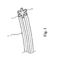
- Figures 1 shows a pipe liner suitable for use with the transition fitting and method of the present invention.
- the liner illustrated generally at 1, has a star-shaped profile with 6 symmetrically-arranged lobes 2. This liner is used to reline a lead pipe 3 of nominal bore in the range of 12.5 to 13.0 mm.
- FIG. 2 there is shown the liner 1 inserted in a lead pipe 3 and protruding a short distance from an end thereof.
- a transition fitting body component 4 is slidable over the end of the lead pipe 3 and is connected to a brass collar 5.
- the brass collar has a hexagonal section 6 and a screw threaded end section 7 which protrude from the fitting body 4.
- An internal circular lip 39 (see Figure 16) on the body component 4 fits into a circular recess 8 on the brass collar 5 in order to make a firm connection therewith.
- the brass collar has a bore with a tapered internal section 9 which extends from an end face 10 of the collar.
- An annular tapered brass insert 11 is shown in Figure 4.
- the insert 11 has a tapered outer face 12, which has the same taper angle as the tapered internal bore section 9 of the collar 5.
- An objective of the transition fitting is to fit the brass insert 11 inside the liner 1 and then to trap the liner between the insert and the inside tapered bore section 9 of the collar 5.
- the invention provides a tool, which is depicted in Figures 5 to 13.
- the insertion tool illustrated generally at 13, comprises a shaft 14 having at its remote end a pressure pad 15, and at its near end an insert carrier 16.
- an insert 11 is shown mounted on the insert carrier 16.
- a carriage 17, slidably mounted upon the shaft 14, comprises a circular plate 18 upon which are pivotally mounted three elongate prongs 19, in a generally cone-shaped configuration.
- the tips 20 of the prongs 19 are urged together by a rubber ring 21 which extends around the base of the prongs 19.
- the tips 20 of the prongs 19 are profiled and have serrations 22 in order to receive and grip an end of the liner 1.
- the length of liner protruding from the lead pipe 3 is pinched between the fingers of the installer to prevent it sliding and the tips 20 of the prongs 19 are inserted into the exposed end of the liner.
- transition fitting body component 4 and brass collar 5 are slid axially along the lead pipe 3 until the insert 11 can be mated with the brass collar 5.
- an internally threaded compression cap 22 has been screwed onto the external thread 6 of the collar 5 to apply axial pressure upon the insert 11, forcing it into the tapered bore 9 of the collar 5 and increasing the compression on the wall of the liner 1.
- a sealing ring 23 is placed over the collar and is seated between the hexagonal section 5 of the collar and a corresponding hexagonal section 24 on the compression cap 22.
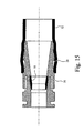
- the compression cap 22 is shown in more detail in Figure 11, where it can be seen to have an internally threaded section 25, which co-operates with the externally threaded section 6 of the collar 5, and a thrust face 26 which presses against the insert 11.
- the compression cap has an internal tapered section 27 which cooperates with the taper of the insert 11 to make a smooth flow channel through the fitting.
- An external thread 28 on the compression cap 22 permits the transition fitting to be connected to other components.
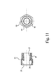
- Figure 13 shows a second design in which the threaded section 28 on the compression cap 22 of Figure 12 is replaced by a ribbed, profiled section 29 on the second compression cap 30. Components using this ribbed, profiled design are sold by Uponor Oy under the Trade Mark Quick & Easy.
- the assembly of the Quick & Easy system is shown in Figure 14.
- a cross-linked polyethylene sleeve 31 is placed over an end of a polyethylene pipe 32 to be connected to the compression cap 30.
- An expansion tool 33 is then used to expand the cross-linked polyethylene sleeve 31 and the end of the polyethylene pipe 32 sufficiently to allow the insertion into the pipe 32 of the profiled section 29 of the compression cap 30.
- FIG. 15 shows the second compression cap 30 inserted into the polyethylene pipe 32, with the outer cross-linked polyethylene sleeve 31 omitted.
- Figure 16 shows one half-shell of the moulded fitting body 4, showing the position of the sliding taper lock plug 34.
- Two taper lock plugs 34 are provided, of which only one is shown.
- the taper lock plugs run in channels 35, which are provided with a ratchet detail 36.
- Each half-shell of the body 4 is provided with a press fit locking hook 37 which engages in a corresponding recess 38 on the other half-shell.
- Circular lips 39 engage with the annular recess 8 in the collar 4.
- Also illustrated in Figure 16 is one of two liner support insert members 40, the function of which will be more particularly described hereinafter.
- the two half-shells of the body 4 are a press fit together and are held by metal circlips 41, 42 which slide over each end of the assembled body 4 as shown in Figure 17.
- the taper lock plugs have protruding integral buttons 43 which enable the taper lock plugs to be moved along the taper of the body 4, in the channels 35, to engage the lead pipe 3 (see Figure 3) forming a connection which resists axial pull-out forces.
- Apertures 48 are sized in order to allow for the axial displacement of the body component 4 and to accommodate the interlocking liner support members 40.
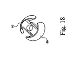
- the interlocking liner support insert members 40 are shown in Figures 18 to 20. Each insert member 40 has an external saddle-shaped portion 44 upon which is mounted a semi-circular liner support 45 on pillars 46. The liner support insert members 40 have extending hooks 47 which are a press fit against shoulders 47a. The assembled interlocked liner support inserts are shown in Figure 18.
- the liner support insert members 40 In installing the liner support insert members 40, they are each inserted into the apertures 48 and pressed together to lock them within the body component 4.
- the interlocked liner supports 45 encircle the unsupported liner and provide the required stability in use.
Abstract

Description
- This invention relates to transition fittings, and more particularly to a transition fitting for an expandable pipe liner and to an insertion tool for introducing an insert into an expandable pipe liner.
- Rehabilitation of water supply pipes is a major problem for many water companies. As an alternative to direct replacement, a variety of methods have been proposed for relining water pipes, such as, for example, those disclosed in WO92/09843, WO92/08922, US474178, WO97/10943, and WO98/54509.
- However such methods are not readily applicable to the small bore pipes customarily used in domestic premises. A large number of such premises are still equipped with lead pipes, which represents a major public health problem as the slightly soluble lead is an accumulative poison.
- As an alternative to complete replacement of lead pipes, it has been proposed in WO97/04269 to line the pipes with a polyethylene film which is everted by fluid pressure into the pipe. In another method, a polyethyleneterepthalate film is extruded as a profile, inserted in the pipe, inflated by fluid pressure and heated in situ. This presses the lining against the inner walls of the pipe and softens the lining to promote thermal bonding to the pipe wall.
- A simpler and cheaper trenchless method by which existing lead water pipes, particularly underground pipes, can be rehabilitated with the minimum of disruption and without the need for expensive plant and equipment is disclosed in WO00/63605. The entire disclosures of all the abovementioned specifications are incorporated herein by reference for all purposes.
- In the method of WO00/63605 there is deployed a tubular liner within a pipe, characterised in that the liner comprises a polyolefin elastomer or a polyolefin plastomer. A polyolefin elastomer has a specific gravity below 870 kg/m3, whereas a polyolefin plastomer has a specific gravity above 870 kg/m3.
- The polyethylene elastomer/plastomer generally comprises a substantially linear ethylene interpolymer, which may comprise 50 to 95% by weight of ethylene, and 5 to 50% by weight of at least one olefinic comonomer, preferably 10 to 25% by weight of the comonomer. Comonomers may contain from 3 to about 20 carbon atoms, and may comprise one or more of propylene, 1-butene, 1-hexene, 4-methyl-1-pentene, 1-heptene, and 1-octene. The specific gravity may be in the range of 830 to 967 kg/m3, preferably 863 to 913 kg/m3 and more preferably 885 to 913 kg/m3, for optimum toughness and flexibility. Preferred comonomers are 1-hexene and especially 1-octene.
- The substantially linear inter polymers are advantageously characterised by a narrow molecular weight distribution, especially from 1.8 to 2.2, and a homogenous comonomer distribution.
- The tubular liner is formed as a pleated tube with longitudinally extending multiple radial pleats, giving a star shaped, multi-lobed, or fluted cross-section. In one embodiment the tube is formed with six radially equispaced pleats, defining an equal number of outwardly projecting lobes. The liner may be deployed within a pipe, by securing one end of the liner adjacent an end of the pipe to which access has been obtained, and pulling the liner through the pipe by means of a cable attached to a foam messenger pig which is propelled through the pipe by fluid pressure. Alternatively, the liner may be pushed and pulled through the host pipe by means of a flexible rod attached to the liner.
- Preferred embodiments of the liner and the method of insertion of the liner into a pipe are disclosed in the body of the specification of WO00/63605. Typically the wall thickness is from 0.25 to 0.55 mm. Such a liner is intended for the rehabilitation of an old lead pipe whose internal diameter is in the range of 10 to 20 mm.
- After installation of the liner, and connection of a transition fitting in order to connect the liner and pipe to another pipe line component, the water supply is reconnected to the pipe. The liner is expanded, by the pressure head in the water supplied through the pipe, into a roughly circular shape, and is then stretched in an elastic manner until it comes into contact with the inside surface of the lead pipe wall.
- Whilst the above described profiled liner has proved to be a good solution to the problem of relining old lead pipes, its non-circular cross-sectional shape has made it very difficult to design a suitable transition fitting. In addition, certain essential design criteria have been laid down for transition fittings which are difficult to meet using this type of liner. These are as follows:
- 1. A water tight fitting must be made to the end of the liner, with integrity to at least the maximum operating pressure expected for the liner. For a domestic water system a maximum working pressure of 8 bar is assumed.
- 2. The liner must be gripped within the transition fitting such that it will not pull out under loading. As a measure of the performance, the liner starts to deform plastically at an elongation level of around 400 to 500% and would be considered unusable after being subjected to this. It is therefore a requirement that the liner shall be retained at the loads generated in straining the liner to 500% of its original size.
- 3. Pressure head loss in lined pipes, particularly at smaller diameters, is a critical issue. The liner must be designed to maximise the bore of any fitting and where possible to minimise the head loss by a smooth transition profile in the connection to other pipe line components.
- 4. The transition fitting must additionally anchor the terminated pipe so that the end load from any attached components is transferred initially to the original pipe. This is because the liner itself has only a limited end load capability. Typically, the liner has a tensile strength of around 300 N, compared to the tensile strength of 20mm SDR 9 polyethylene pipe which has a tensile strength of around 2000 N.
- 5. After installation there should be no unsupported sections of liner in the vicinity of the transition fitting.
-
- It is apparent that there is a need for a new transition fitting and installation method capable of meeting at least some, and preferably all, of the above requirements.
- In a first aspect the invention provides a transition fitting for an expandable pipe liner which comprises:
- an externally tapered insert adapted to be received inside the expandable pipe liner;
- An internally tapered collar adapted to co-operate with the tapered insert in order to grip the expandable pipe liner there between; and
- An internally threaded compression cap adapted to co-operate with the tapered collar to apply a compressive load to the tapered insert and thereby increase the gripping force between the insert and the collar.
-
- In a second aspect, the invention provides a transition fitting for a pipe, the pipe having an expandable liner disposed therein, which liner has an unsupported length extending from an end of the pipe, the fitting comprising:
- A tubular body, dimensioned to fit over the end of the pipe, the tubular body having at least one orifice in the tubular wall thereof;
- means for securing the fitting to the pipe;
- means for securing the fitting to the expandable liner; and
- liner support means adapted to be received in the tubular body through the orifice and to support an unsupported length of liner within the fitting.
-
- In a third aspect, the invention provides an insertion tool for introducing an insert into an expandable pipe liner which comprises:
- an array of outwardly deflectable, elongate prongs arranged in a conical array and adapted to expand an expandable pipe liner positioned there over; and
- an insert carrier adapted to receive an annular insert thereon, the insert carrier being axially disposed within the conical array of prongs and axially moveable with respect thereto;
- the arrangement being such that movement of the insert carrier and insert towards the apex of the conical array of prongs forces the elongate prongs apart, expanding the expandable liner, such that the insert is conveyed through the conical array of prongs and into the expanded liner, and such that withdrawal of the insert carrier leaves the insert positioned in the expandable liner.
-
- In a preferred embodiment of a transition fitting according to the invention, the tubular body of the second aspect of the invention is secured to the expandable liner by means of the tapered insert, collar and compression cap of the first aspect of the invention.
- In a fourth aspect of the invention there is provided a method for introducing an insert into an expandable pipe liner, in which there is used an insertion tool, the tool comprising an array of outwardly deflectable elongate prongs arranged in a conical array and adapted to expand an expandable pipe liner positioned thereover and an insert carrier adapted to receive an insert thereon, the insert being axially disposed within the conical array of prongs and axially moveable with respect thereto,
the method comprising disposing an annular insert on the insert carrier, positioning an expandable pipe liner over the conical array of prongs, moving the insert carrier and insert towards the apex of the conical array of prongs such that the prongs are forced apart, expanding the expandable liner, forwarding the insert and insert carrier through the conical array of prongs such that the insert is positioned in the expanded pipe liner, and withdrawing the insert carrier leaving the insert positioned in the expandable pipe liner. - The insert preferably has an external tapered face which has the same taper angle as the internal tapered face of the collar. Both components are preferably machined from brass, or another suitable metallic material, or injection moulded from a suitable engineering plastics material.
- Preferably the tubular body has two opposed orifices in the tubular wall thereof and the liner support means comprises interlocking profiles which can be inserted through the orifices and joined to form a cylindrical support for the unsupported length of expandable liner.
- Preferably the means for securing the fitting to the pipe comprises one or more taper lock plugs disposed within the tubular body of the fitting.
- Certain preferred embodiments of the invention will now be described, by way of example only, with reference to the accompanying Drawings in which:
- Figure 1 shows a perspective view of a length of star shaped multi-lobed cross section expandable liner of the type described in WO00/63605;
- Figure 2 shows a side elevation of a female body component and a collar of a transition fitting according to the invention, assembled on an end of a relined lead pipe with a portion of the star shaped cross section liner protruding from the end of the pipe;
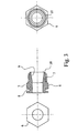
- Figure 3 shows a side elevation in section, and two end elevations of the collar of Figure 2;
- Figure 4 shows a side elevation in section, and an end elevation of a tapered insert for use in a transition fitting according to the invention;
- Figure 5 shows a perspective view of an expansion tool according to the invention with the insert of Figure 4 in position on the insert carrier;
- Figure 6 shows the assembly of Figure 2 with the expansion tool of Figure 5 engaged with the end of the star shaped cross section liner;
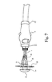
- Figure 7 shows the arrangement of Figure 6 with the insert carrier pushed forward to expand the prongs and force the insert into the end of the liner;
- Figure 8 shows the arrangement of Figure 7 with the insertion tool removed and the tapered insert remaining in the end of the star shaped cross section liner;
- Figure 9 shows the arrangement of Figure 8 with the insert pressed into the collar;
- Figure 10 shows the arrangement of Figure 9 with a compression cap screwed onto the collar;
- Figure 11 shows a side elevation in section, and an end elevation of the compression cap of Figure 10;
- Figure 12 shows a side elevation in section of the assembly of the collar, insert, compression cap and star shaped cross section liner of Figure 10;
- Figure 13 shows an exploded perspective view of the collar and insert of Figure 12 provided with a second embodiment of a compression cap;
- Figure 14 shows a perspective view of apparatus for assembling the second compression cap of Figure 13 onto a polyethylene pipe;
- Figure 15 shows a side elevation in section of the assembly of Figure 13 connected to a polyethylene pipe;
- Figure 16 shows a perspective view, partly in section and with parts broken away, of the transition fitting body component of Figure 3 showing the sliding taper lock plugs;
- Figure 17 shows an exploded view of the parts of a complete transition fitting in accordance with one preferred aspect of the invention, in as-supplied condition;
- Figure 18 shows a perspective view of a pair of interlocking liner support members for use in a transition fitting in accordance with one aspect of the invention in interlocked relationship; and
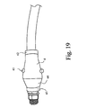
- Figure 19 shows a perspective view of a fully assembled transition fitting according to the invention.
-
- Referring to the Drawings, Figures 1 shows a pipe liner suitable for use with the transition fitting and method of the present invention. The liner, illustrated generally at 1, has a star-shaped profile with 6 symmetrically-arranged
lobes 2. This liner is used to reline alead pipe 3 of nominal bore in the range of 12.5 to 13.0 mm. - Referring now to Figure 2, there is shown the
liner 1 inserted in alead pipe 3 and protruding a short distance from an end thereof. A transitionfitting body component 4 is slidable over the end of thelead pipe 3 and is connected to abrass collar 5. The brass collar has ahexagonal section 6 and a screw threadedend section 7 which protrude from thefitting body 4. An internal circular lip 39 (see Figure 16) on thebody component 4 fits into acircular recess 8 on thebrass collar 5 in order to make a firm connection therewith. As shown in Figure 3, the brass collar has a bore with a tapered internal section 9 which extends from anend face 10 of the collar.
An annular taperedbrass insert 11 is shown in Figure 4. Theinsert 11 has a taperedouter face 12, which has the same taper angle as the tapered internal bore section 9 of thecollar 5. An objective of the transition fitting is to fit thebrass insert 11 inside theliner 1 and then to trap the liner between the insert and the inside tapered bore section 9 of thecollar 5. - To achieve the expansion of the liner, and the placement of the insert, the invention provides a tool, which is depicted in Figures 5 to 13. Referring to Figure 5, the insertion tool, illustrated generally at 13, comprises a
shaft 14 having at its remote end apressure pad 15, and at its near end aninsert carrier 16. - In Figure 5 an
insert 11 is shown mounted on theinsert carrier 16. Acarriage 17, slidably mounted upon theshaft 14, comprises acircular plate 18 upon which are pivotally mounted threeelongate prongs 19, in a generally cone-shaped configuration. Thetips 20 of theprongs 19 are urged together by arubber ring 21 which extends around the base of theprongs 19. Thetips 20 of theprongs 19 are profiled and haveserrations 22 in order to receive and grip an end of theliner 1. Although in the illustration only three prongs are shown, it would be possible to have 4, 5, 6 or indeed a greater number of prongs depending upon the diameter of the liner. - In order to expand the
liner 1 using theinsertion tool 13, the length of liner protruding from thelead pipe 3 is pinched between the fingers of the installer to prevent it sliding and thetips 20 of theprongs 19 are inserted into the exposed end of the liner. - In Figure 6 the
insertion tool 13 is shown engaged with the end of the liner with thetips 20 of theprongs 19 inserted therein prior to the expansion step. - In Figure 7, hand pressure applied to the
pad 15 moves theinsert carrier 16 forward, relative to thecarriage 17, expanding the prongs against the tension of therubber ring 21 and expanding the end of theliner 1. Once the liner has been expanded sufficiently the insert carrier pushes the insert into the end of the liner where it is gripped and retained. During this procedure it is preferred to keep the liner pinched between the fingers in order to overcome any tendency for the thrust generated by theinsert carrier 16 to push theinsertion tool 13 off the end of the liner, and instead force the liner to expand. Figure 8 shows the stage at which theinsertion tool 13 has been removed leaving the taperedinsert 11 gripped by the end of theliner 1. - After removal of the insertion tool the transition
fitting body component 4 andbrass collar 5 are slid axially along thelead pipe 3 until theinsert 11 can be mated with thebrass collar 5. - In Figure 9 the
insert 11 has been pushed under hand pressure into thebrass collar 5 thus compressing the wall of theliner 1 between the tapered walls of the collar and the insert. - In Figure 10 an internally threaded
compression cap 22 has been screwed onto theexternal thread 6 of thecollar 5 to apply axial pressure upon theinsert 11, forcing it into the tapered bore 9 of thecollar 5 and increasing the compression on the wall of theliner 1. A sealingring 23 is placed over the collar and is seated between thehexagonal section 5 of the collar and a correspondinghexagonal section 24 on thecompression cap 22. Thecompression cap 22 is shown in more detail in Figure 11, where it can be seen to have an internally threadedsection 25, which co-operates with the externally threadedsection 6 of thecollar 5, and athrust face 26 which presses against theinsert 11. The compression cap has an internaltapered section 27 which cooperates with the taper of theinsert 11 to make a smooth flow channel through the fitting. Anexternal thread 28 on thecompression cap 22 permits the transition fitting to be connected to other components. - The assembled compression cap, collar and insert are shown in cross section in Figure 12.
- Figure 13 shows a second design in which the threaded
section 28 on thecompression cap 22 of Figure 12 is replaced by a ribbed, profiledsection 29 on thesecond compression cap 30. Components using this ribbed, profiled design are sold by Uponor Oy under the Trade Mark Quick & Easy. The assembly of the Quick & Easy system is shown in Figure 14. Across-linked polyethylene sleeve 31 is placed over an end of apolyethylene pipe 32 to be connected to thecompression cap 30. Anexpansion tool 33 is then used to expand thecross-linked polyethylene sleeve 31 and the end of thepolyethylene pipe 32 sufficiently to allow the insertion into thepipe 32 of the profiledsection 29 of thecompression cap 30. After the tool is removed and the compression cap inserted in position, the cross-linked polyethylene sleeve recovers and forces the polyethylene pipe into tight conformity with the profiledsection 29 of thecompression cap 30. Figure 15 shows thesecond compression cap 30 inserted into thepolyethylene pipe 32, with the outercross-linked polyethylene sleeve 31 omitted. - Figure 16 shows one half-shell of the moulded
fitting body 4, showing the position of the slidingtaper lock plug 34. Two taper lock plugs 34 are provided, of which only one is shown. The taper lock plugs run inchannels 35, which are provided with aratchet detail 36. Each half-shell of thebody 4 is provided with a pressfit locking hook 37 which engages in acorresponding recess 38 on the other half-shell.Circular lips 39 engage with theannular recess 8 in thecollar 4. Also illustrated in Figure 16 is one of two linersupport insert members 40, the function of which will be more particularly described hereinafter. The two half-shells of thebody 4 are a press fit together and are held bymetal circlips body 4 as shown in Figure 17. As can be seen from Figure 17, the taper lock plugs have protrudingintegral buttons 43 which enable the taper lock plugs to be moved along the taper of thebody 4, in thechannels 35, to engage the lead pipe 3 (see Figure 3) forming a connection which resists axial pull-out forces. - By sliding the
body component 4 andbrass collar 5 axially along the lead pipe in order to mate thebrass collar 5 with theinsert 11, a length of the liner is left unsupported within the fitting, as can be seen through theapertures 48 in Figure 10.Apertures 48 are sized in order to allow for the axial displacement of thebody component 4 and to accommodate the interlockingliner support members 40. - The interlocking liner
support insert members 40 are shown in Figures 18 to 20. Eachinsert member 40 has an external saddle-shapedportion 44 upon which is mounted asemi-circular liner support 45 on pillars 46. The linersupport insert members 40 have extending hooks 47 which are a press fit against shoulders 47a. The assembled interlocked liner support inserts are shown in Figure 18. - In installing the liner
support insert members 40, they are each inserted into theapertures 48 and pressed together to lock them within thebody component 4. The interlocked liner supports 45 encircle the unsupported liner and provide the required stability in use. - The fully assembled transition fitting is illustrated in Figure 21.
- Tests on a fitting in accordance with the invention have shown excellent results and have met all the design criteria.
- The reader's attention is directed to all papers and documents which are filed concurrently with or previous to this specification in connection with this application and which are open to public inspection with this specification, and the contents of all such papers and documents are incorporated herein by reference.
- All of the features disclosed in this specification (including any accompanying claims, abstract and drawings), and/or all of the steps of any method or process so disclosed, may be combined in any combination, except combinations where at least some of such features and/or steps are mutually exclusive.
- Each feature disclosed in this specification (including any accompanying claims, abstract and drawings), may be replaced by alternative features serving the same, equivalent or similar purpose, unless expressly stated otherwise. Thus, unless expressly stated otherwise, each feature disclosed is one example only of a generic series of equivalent or similar features.
- The invention is not restricted to the details of any foregoing embodiments. The invention extends to any novel one, or any novel combination, of the features disclosed in this specification (including any accompanying claims, abstract and drawings), or to any novel one, or any novel combination, of the steps of any method or process so disclosed.
Claims (27)
- A transition fitting for an expandable pipe liner which comprises:an externally tapered insert adapted to be received inside the expandable pipe liner;An internally tapered collar adapted to co-operate with the tapered insert in order to grip the expandable pipe liner there between; andAn internally threaded compression cap adapted to co-operate with the internally tapered collar to apply a compressive load to the tapered insert and thereby increase the gripping force between the insert and the collar.
- A transition fitting according to claim 1, in which the insert has an external tapered face which has substantially the same taper angle as the internal tapered face of the collar.
- A transition fitting according to claim 1 or 2, in which the insert and the collar are machined from brass, or another suitable metallic material, or injection moulded from a suitable engineering plastics material.
- A transition fitting according to any one of the preceding claims, in which the internally tapered collar is provided with connecting means for connection to a body component adapted to fit over and be secured to a pipe end.
- A transition fitting according to any one of the preceding claims, in which the internally tapered collar is provided with a circular recess and the body component is provided with an internal circular lip which fits into the circular recess.
- A transition fitting according to any one of the preceding claims, in which the compression cap has an externally threaded section for connection to another component.
- A transition fitting according to any one of claims 1 to 5, in which the compression cap has a ribbed, profiled section for connection to another component.
- A transition fitting according to any one of claims 1 to 7 substantially as hereinbefore described with reference to and as illustrated in the accompanying Drawings.
- A transition fitting according to any one of claims 1 to 8 substantially as hereinbefore described.
- A transition fitting for a pipe, the pipe having an expandable liner disposed therein, which liner has an unsupported length extending from an end of the pipe, the fitting comprising:A tubular body, dimensioned to fit over the end of the pipe, the tubular body having at least one orifice in the tubular wall thereof;means for securing the fitting to the pipe;means for securing the fitting to the expandable liner; andliner support means adapted to be received in the tubular body through the orifice and to support an unsupported length of liner within the fitting.
- A transition fitting according to claim 10, in which the tubular body has two opposed orifices in the tubular wall thereof and the liner support means comprises interlocking profiles which can be inserted through the orifices and joined to form a cylindrical support for the unsupported length of expandable liner.
- A transition fitting according to claim 10 or 11, in which the tubular body is formed from two half-shells.
- A transition fitting according to any one of claims 10 to 12, in which the means for connecting the tubular body to the pipe comprises one or more taper lock plugs.
- A transition fitting according to claim 13, in which each of the one or more taper lock plugs slides in a channel in the tubular body.
- A transition fitting according to any one of claims 10 to 14, in which the means for securing the fitting to the expandable liner comprises an externally tapered insert adapted to be received inside the expandable pipe liner;
An internally tapered collar adapted to co-operate with the tapered insert in order to grip the expandable pipe liner there between, the collar being provided with a circular recess; and
An internally threaded compression cap adapted to co-operate with the internally tapered collar to apply an end load to the tapered insert and thereby increase the gripping force between the insert and the collar,
the body component being provided with an internal circular lip which fits into the circular recess on the collar. - A transition fitting according to any one of claims 10 to 15 substantially as hereinbefore described with reference to and as illustrated in the accompanying Drawings.
- A transition fitting according to any one of claims 10 to 16 substantially as hereinbefore described.
- An insertion tool for introducing an insert into an expandable pipe liner which comprises:an array of outwardly deflectable, elongate prongs arranged in a conical array and adapted to expand an expandable pipe liner positioned there over; andan insert carrier adapted to receive an annular insert thereon, the insert being axially disposed within the conical array of prongs and axially moveable with respect thereto;the arrangement being such that movement of the insert carrier and insert towards the apex of the conical array of prongs forces the elongate prongs apart, expanding the expandable liner, such that the insert is conveyed through the conical array of prongs and into the expanded liner, and such that withdrawal of the insert carrier leaves the insert positioned in the expandable liner.
- An insertion tool according to claim 18, which is provided with three or four prongs.
- An insertion tool according to claim 18 or 19, in which the prongs are profiled and have serrations in order to receive and grip an end of the liner.
- An insertion tool according to any one of claims 18 to 20, in which the tool comprises a carriage, slidably mounted on a shaft, the carriage comprising a circular plate upon which the prongs are pivotally mounted.
- An insertion tool according to any one of claims 18 to 21 substantially as hereinbefore described with reference to and as illustrated in the accompanying Drawings.
- An insertion tool according to any one of claims 18 to 22 substantially as hereinbefore described.
- A method for introducing an insert into an expandable pipe liner, in which there is used an insertion tool comprising an array of outwardly deflectable elongate prongs arranged in a conical array and adapted to expand an expandable pipe liner positioned thereover and an insert carrier adapted to receive an insert thereon, the insert being axially disposed within the conical array of prongs and axially moveable with respect thereto,
the method comprising disposing an annular insert on the insert carrier, positioning an expandable pipe liner over the conical array of prongs, moving the insert carrier and insert towards the apex of the conical array of prongs such that the prongs are forced apart, expanding the expandable liner, forwarding the insert and insert carrier through the conical array of prongs such that the insert is positioned in the expanded pipe liner, and withdrawing the insert carrier leaving the insert positioned in the expandable pipe liner. - A method according to claim 24, in which there is used an insertion tool according to any one of claims 18 to 23.
- A method according to claim 24 or 25, in which the insert forms part of a transition fitting according to any one of claims 1 to 17, and in which the insert is positioned within an internally tapered collar adapted to co-operate with the insert in order to grip the liner therebetween.
- A method according to any one of claims 24 to 26 substantially as hereinbefore described.
Applications Claiming Priority (2)
| Application Number | Priority Date | Filing Date | Title |
|---|---|---|---|
| GB0212809 | 2002-06-05 | ||
| GB0212809A GB2389399B (en) | 2002-06-05 | 2002-06-05 | Transition fitting |
Publications (3)
| Publication Number | Publication Date |
|---|---|
| EP1369637A2 true EP1369637A2 (en) | 2003-12-10 |
| EP1369637A3 EP1369637A3 (en) | 2004-03-03 |
| EP1369637B1 EP1369637B1 (en) | 2005-12-14 |
Family
ID=9937941
Family Applications (1)
| Application Number | Title | Priority Date | Filing Date |
|---|---|---|---|
| EP03253434A Expired - Lifetime EP1369637B1 (en) | 2002-06-05 | 2003-05-31 | Transition fitting for a pipe liner |
Country Status (4)
| Country | Link |
|---|---|
| EP (1) | EP1369637B1 (en) |
| AT (1) | ATE313038T1 (en) |
| DE (1) | DE60302707D1 (en) |
| GB (1) | GB2389399B (en) |
Cited By (1)
| Publication number | Priority date | Publication date | Assignee | Title |
|---|---|---|---|---|
| CN103753949A (en) * | 2013-12-31 | 2014-04-30 | 广州丽盈塑料有限公司 | Tool structure for printing of headless hose |
Citations (10)
| Publication number | Priority date | Publication date | Assignee | Title |
|---|---|---|---|---|
| US550560A (en) * | 1895-11-26 | Tire-repairing tool | ||
| US2709606A (en) * | 1949-01-14 | 1955-05-31 | Mueller Co | Pipe coupling having perforated socket for solder |
| DE1223136B (en) * | 1962-10-31 | 1966-08-18 | Shell Int Research | Device for applying the end part of expandable hoses to a body, the cross-section of which in the application plane protrudes larger than the inner cross-section of the hose |
| US4622197A (en) * | 1983-10-01 | 1986-11-11 | Standard Telephones And Cables Public Limited Company | Applying thermoplastics sleeve to crush resistant tubing |
| US4679826A (en) * | 1985-05-06 | 1987-07-14 | Flow Industries, Inc. | High pressure hose fitting |
| JPH04146031A (en) * | 1990-10-09 | 1992-05-20 | Bridgestone Corp | Method for inserting arbor into cylindrical rubber and device therefor |
| GB2263744A (en) * | 1989-09-22 | 1993-08-04 | British Gas Plc | Sealant head |
| NL9500454A (en) * | 1995-03-07 | 1996-10-01 | Watson B V | Device for coupling two pipes |
| WO1998026207A1 (en) * | 1996-12-13 | 1998-06-18 | Polyline Technologies Limited | Lining pipes |
| WO2000063605A1 (en) * | 1999-04-15 | 2000-10-26 | Suez Lyonnaise Des Eaux | Rehabilitation of water supply pipes |
Family Cites Families (3)
| Publication number | Priority date | Publication date | Assignee | Title |
|---|---|---|---|---|
| US5178423A (en) * | 1990-02-28 | 1993-01-12 | Alberto Combeau | Fast assembly for flexible pipings |
| US5452921A (en) * | 1991-10-31 | 1995-09-26 | The Deutsch Company | Axially swaged fitting |
| NO972019L (en) * | 1997-04-30 | 1998-11-02 | Olimb As Kristian | End of pipe |
-
2002
- 2002-06-05 GB GB0212809A patent/GB2389399B/en not_active Revoked
-
2003
- 2003-05-31 AT AT03253434T patent/ATE313038T1/en not_active IP Right Cessation
- 2003-05-31 EP EP03253434A patent/EP1369637B1/en not_active Expired - Lifetime
- 2003-05-31 DE DE60302707T patent/DE60302707D1/en not_active Expired - Lifetime
Patent Citations (10)
| Publication number | Priority date | Publication date | Assignee | Title |
|---|---|---|---|---|
| US550560A (en) * | 1895-11-26 | Tire-repairing tool | ||
| US2709606A (en) * | 1949-01-14 | 1955-05-31 | Mueller Co | Pipe coupling having perforated socket for solder |
| DE1223136B (en) * | 1962-10-31 | 1966-08-18 | Shell Int Research | Device for applying the end part of expandable hoses to a body, the cross-section of which in the application plane protrudes larger than the inner cross-section of the hose |
| US4622197A (en) * | 1983-10-01 | 1986-11-11 | Standard Telephones And Cables Public Limited Company | Applying thermoplastics sleeve to crush resistant tubing |
| US4679826A (en) * | 1985-05-06 | 1987-07-14 | Flow Industries, Inc. | High pressure hose fitting |
| GB2263744A (en) * | 1989-09-22 | 1993-08-04 | British Gas Plc | Sealant head |
| JPH04146031A (en) * | 1990-10-09 | 1992-05-20 | Bridgestone Corp | Method for inserting arbor into cylindrical rubber and device therefor |
| NL9500454A (en) * | 1995-03-07 | 1996-10-01 | Watson B V | Device for coupling two pipes |
| WO1998026207A1 (en) * | 1996-12-13 | 1998-06-18 | Polyline Technologies Limited | Lining pipes |
| WO2000063605A1 (en) * | 1999-04-15 | 2000-10-26 | Suez Lyonnaise Des Eaux | Rehabilitation of water supply pipes |
Non-Patent Citations (1)
| Title |
|---|
| PATENT ABSTRACTS OF JAPAN vol. 016, no. 426 (M-1306), 8 September 1992 (1992-09-08) -& JP 04 146031 A (BRIDGESTONE CORP), 20 May 1992 (1992-05-20) * |
Cited By (2)
| Publication number | Priority date | Publication date | Assignee | Title |
|---|---|---|---|---|
| CN103753949A (en) * | 2013-12-31 | 2014-04-30 | 广州丽盈塑料有限公司 | Tool structure for printing of headless hose |
| CN103753949B (en) * | 2013-12-31 | 2017-04-12 | 广州丽盈塑料有限公司 | Tool structure for printing of headless hose |
Also Published As
| Publication number | Publication date |
|---|---|
| GB2389399B (en) | 2006-01-11 |
| ATE313038T1 (en) | 2005-12-15 |
| GB0212809D0 (en) | 2002-07-10 |
| DE60302707D1 (en) | 2006-01-19 |
| GB2389399A (en) | 2003-12-10 |
| EP1369637B1 (en) | 2005-12-14 |
| EP1369637A3 (en) | 2004-03-03 |
| GB2389399A9 (en) | 2005-06-23 |
Similar Documents
| Publication | Publication Date | Title |
|---|---|---|
| US6345431B1 (en) | Joining thermoplastic pipe to a coupling | |
| US7134204B2 (en) | Integral restraint system and method of manufacture for plastic pipe | |
| CA1073497A (en) | Quick connect coupling | |
| US8770630B2 (en) | Hose connecting method and connector arrangement | |
| US7163238B1 (en) | Connector for flexible and semi-rigid pipings | |
| US20110309616A1 (en) | Sanitary hose coupling | |
| US6832791B2 (en) | Connection means for interconnecting two duct elements | |
| US9080704B2 (en) | Universal pipe coupler | |
| JP2007500828A (en) | Tubular metal fittings expandable in wall openings and methods of installation | |
| US20200011460A1 (en) | Pipe fitting apparatus and methods | |
| WO2007049053A1 (en) | Hose connector | |
| EP1800047B1 (en) | Pipe coupling | |
| US20040178630A1 (en) | Pipe coupling | |
| US3532365A (en) | Coupling | |
| EP1369637B1 (en) | Transition fitting for a pipe liner | |
| GB2225406A (en) | Methods and apparatus for use in pipe lining. | |
| GB2416577A (en) | Transition fittings | |
| GB2416576A (en) | Transition fittings | |
| US5683116A (en) | O-ring push-pull pipe joint | |
| US8709318B2 (en) | Method and apparatus for belling plastic pipe | |
| US20070126231A1 (en) | Coupling with pull-out resistance | |
| RU64318U1 (en) | PIPE JOINT ASSEMBLY | |
| EP1927807A1 (en) | A quick-release connection device, particularly for pipes and the like | |
| US20030034647A1 (en) | Removable pipe coupler | |
| EP1179409B1 (en) | Method and apparatus for bell-shaping the ends of pipes |
Legal Events
| Date | Code | Title | Description |
|---|---|---|---|
| PUAI | Public reference made under article 153(3) epc to a published international application that has entered the european phase |
Free format text: ORIGINAL CODE: 0009012 |
|
| 17P | Request for examination filed |
Effective date: 20030610 |
|
| AK | Designated contracting states |
Kind code of ref document: A2 Designated state(s): AT BE BG CH CY CZ DE DK EE ES FI FR GB GR HU IE IT LI LU MC NL PT RO SE SI SK TR |
|
| AX | Request for extension of the european patent |
Extension state: AL LT LV MK |
|
| PUAL | Search report despatched |
Free format text: ORIGINAL CODE: 0009013 |
|
| AK | Designated contracting states |
Kind code of ref document: A3 Designated state(s): AT BE BG CH CY CZ DE DK EE ES FI FR GB GR HU IE IT LI LU MC NL PT RO SE SI SK TR |
|
| AX | Request for extension of the european patent |
Extension state: AL LT LV MK |
|
| AKX | Designation fees paid |
Designated state(s): AT BE BG CH CY CZ DE DK EE ES FI FR GB GR HU IE IT LI LU MC NL PT RO SE SI SK TR |
|
| 17Q | First examination report despatched |
Effective date: 20050126 |
|
| GRAP | Despatch of communication of intention to grant a patent |
Free format text: ORIGINAL CODE: EPIDOSNIGR1 |
|
| GRAS | Grant fee paid |
Free format text: ORIGINAL CODE: EPIDOSNIGR3 |
|
| GRAA | (expected) grant |
Free format text: ORIGINAL CODE: 0009210 |
|
| AK | Designated contracting states |
Kind code of ref document: B1 Designated state(s): AT BE BG CH CY CZ DE DK EE ES FI FR GB GR HU IE IT LI LU MC NL PT RO SE SI SK TR |
|
| PG25 | Lapsed in a contracting state [announced via postgrant information from national office to epo] |
Ref country code: IT Free format text: LAPSE BECAUSE OF FAILURE TO SUBMIT A TRANSLATION OF THE DESCRIPTION OR TO PAY THE FEE WITHIN THE PRESCRIBED TIME-LIMIT;WARNING: LAPSES OF ITALIAN PATENTS WITH EFFECTIVE DATE BEFORE 2007 MAY HAVE OCCURRED AT ANY TIME BEFORE 2007. THE CORRECT EFFECTIVE DATE MAY BE DIFFERENT FROM THE ONE RECORDED. Effective date: 20051214 Ref country code: AT Free format text: LAPSE BECAUSE OF FAILURE TO SUBMIT A TRANSLATION OF THE DESCRIPTION OR TO PAY THE FEE WITHIN THE PRESCRIBED TIME-LIMIT Effective date: 20051214 Ref country code: FI Free format text: LAPSE BECAUSE OF FAILURE TO SUBMIT A TRANSLATION OF THE DESCRIPTION OR TO PAY THE FEE WITHIN THE PRESCRIBED TIME-LIMIT Effective date: 20051214 Ref country code: NL Free format text: LAPSE BECAUSE OF FAILURE TO SUBMIT A TRANSLATION OF THE DESCRIPTION OR TO PAY THE FEE WITHIN THE PRESCRIBED TIME-LIMIT Effective date: 20051214 Ref country code: SK Free format text: LAPSE BECAUSE OF FAILURE TO SUBMIT A TRANSLATION OF THE DESCRIPTION OR TO PAY THE FEE WITHIN THE PRESCRIBED TIME-LIMIT Effective date: 20051214 Ref country code: SI Free format text: LAPSE BECAUSE OF FAILURE TO SUBMIT A TRANSLATION OF THE DESCRIPTION OR TO PAY THE FEE WITHIN THE PRESCRIBED TIME-LIMIT Effective date: 20051214 Ref country code: CH Free format text: LAPSE BECAUSE OF FAILURE TO SUBMIT A TRANSLATION OF THE DESCRIPTION OR TO PAY THE FEE WITHIN THE PRESCRIBED TIME-LIMIT Effective date: 20051214 Ref country code: CZ Free format text: LAPSE BECAUSE OF FAILURE TO SUBMIT A TRANSLATION OF THE DESCRIPTION OR TO PAY THE FEE WITHIN THE PRESCRIBED TIME-LIMIT Effective date: 20051214 Ref country code: BE Free format text: LAPSE BECAUSE OF FAILURE TO SUBMIT A TRANSLATION OF THE DESCRIPTION OR TO PAY THE FEE WITHIN THE PRESCRIBED TIME-LIMIT Effective date: 20051214 Ref country code: RO Free format text: LAPSE BECAUSE OF FAILURE TO SUBMIT A TRANSLATION OF THE DESCRIPTION OR TO PAY THE FEE WITHIN THE PRESCRIBED TIME-LIMIT Effective date: 20051214 Ref country code: LI Free format text: LAPSE BECAUSE OF FAILURE TO SUBMIT A TRANSLATION OF THE DESCRIPTION OR TO PAY THE FEE WITHIN THE PRESCRIBED TIME-LIMIT Effective date: 20051214 |
|
| REG | Reference to a national code |
Ref country code: GB Ref legal event code: FG4D |
|
| REG | Reference to a national code |
Ref country code: CH Ref legal event code: EP |
|
| REG | Reference to a national code |
Ref country code: IE Ref legal event code: FG4D |
|
| REF | Corresponds to: |
Ref document number: 60302707 Country of ref document: DE Date of ref document: 20060119 Kind code of ref document: P |
|
| PG25 | Lapsed in a contracting state [announced via postgrant information from national office to epo] |
Ref country code: SE Free format text: LAPSE BECAUSE OF FAILURE TO SUBMIT A TRANSLATION OF THE DESCRIPTION OR TO PAY THE FEE WITHIN THE PRESCRIBED TIME-LIMIT Effective date: 20060314 Ref country code: BG Free format text: LAPSE BECAUSE OF FAILURE TO SUBMIT A TRANSLATION OF THE DESCRIPTION OR TO PAY THE FEE WITHIN THE PRESCRIBED TIME-LIMIT Effective date: 20060314 Ref country code: GR Free format text: LAPSE BECAUSE OF FAILURE TO SUBMIT A TRANSLATION OF THE DESCRIPTION OR TO PAY THE FEE WITHIN THE PRESCRIBED TIME-LIMIT Effective date: 20060314 Ref country code: DK Free format text: LAPSE BECAUSE OF FAILURE TO SUBMIT A TRANSLATION OF THE DESCRIPTION OR TO PAY THE FEE WITHIN THE PRESCRIBED TIME-LIMIT Effective date: 20060314 |
|
| PG25 | Lapsed in a contracting state [announced via postgrant information from national office to epo] |
Ref country code: DE Free format text: LAPSE BECAUSE OF FAILURE TO SUBMIT A TRANSLATION OF THE DESCRIPTION OR TO PAY THE FEE WITHIN THE PRESCRIBED TIME-LIMIT Effective date: 20060315 |
|
| PG25 | Lapsed in a contracting state [announced via postgrant information from national office to epo] |
Ref country code: ES Free format text: LAPSE BECAUSE OF FAILURE TO SUBMIT A TRANSLATION OF THE DESCRIPTION OR TO PAY THE FEE WITHIN THE PRESCRIBED TIME-LIMIT Effective date: 20060325 |
|
| PG25 | Lapsed in a contracting state [announced via postgrant information from national office to epo] |
Ref country code: PT Free format text: LAPSE BECAUSE OF FAILURE TO SUBMIT A TRANSLATION OF THE DESCRIPTION OR TO PAY THE FEE WITHIN THE PRESCRIBED TIME-LIMIT Effective date: 20060515 |
|
| PG25 | Lapsed in a contracting state [announced via postgrant information from national office to epo] |
Ref country code: IE Free format text: LAPSE BECAUSE OF NON-PAYMENT OF DUE FEES Effective date: 20060531 Ref country code: MC Free format text: LAPSE BECAUSE OF NON-PAYMENT OF DUE FEES Effective date: 20060531 |
|
| NLV1 | Nl: lapsed or annulled due to failure to fulfill the requirements of art. 29p and 29m of the patents act | ||
| PG25 | Lapsed in a contracting state [announced via postgrant information from national office to epo] |
Ref country code: HU Free format text: LAPSE BECAUSE OF FAILURE TO SUBMIT A TRANSLATION OF THE DESCRIPTION OR TO PAY THE FEE WITHIN THE PRESCRIBED TIME-LIMIT Effective date: 20060615 |
|
| REG | Reference to a national code |
Ref country code: CH Ref legal event code: PL |
|
| PLBE | No opposition filed within time limit |
Free format text: ORIGINAL CODE: 0009261 |
|
| STAA | Information on the status of an ep patent application or granted ep patent |
Free format text: STATUS: NO OPPOSITION FILED WITHIN TIME LIMIT |
|
| 26N | No opposition filed |
Effective date: 20060915 |
|
| EN | Fr: translation not filed | ||
| REG | Reference to a national code |
Ref country code: IE Ref legal event code: MM4A |
|
| GBPC | Gb: european patent ceased through non-payment of renewal fee |
Effective date: 20070531 |
|
| PG25 | Lapsed in a contracting state [announced via postgrant information from national office to epo] |
Ref country code: FR Free format text: LAPSE BECAUSE OF FAILURE TO SUBMIT A TRANSLATION OF THE DESCRIPTION OR TO PAY THE FEE WITHIN THE PRESCRIBED TIME-LIMIT Effective date: 20070202 |
|
| PG25 | Lapsed in a contracting state [announced via postgrant information from national office to epo] |
Ref country code: GB Free format text: LAPSE BECAUSE OF NON-PAYMENT OF DUE FEES Effective date: 20070531 |
|
| PG25 | Lapsed in a contracting state [announced via postgrant information from national office to epo] |
Ref country code: EE Free format text: LAPSE BECAUSE OF FAILURE TO SUBMIT A TRANSLATION OF THE DESCRIPTION OR TO PAY THE FEE WITHIN THE PRESCRIBED TIME-LIMIT Effective date: 20051214 |
|
| PG25 | Lapsed in a contracting state [announced via postgrant information from national office to epo] |
Ref country code: TR Free format text: LAPSE BECAUSE OF FAILURE TO SUBMIT A TRANSLATION OF THE DESCRIPTION OR TO PAY THE FEE WITHIN THE PRESCRIBED TIME-LIMIT Effective date: 20051214 Ref country code: LU Free format text: LAPSE BECAUSE OF NON-PAYMENT OF DUE FEES Effective date: 20060531 |
|
| PG25 | Lapsed in a contracting state [announced via postgrant information from national office to epo] |
Ref country code: FR Free format text: LAPSE BECAUSE OF FAILURE TO SUBMIT A TRANSLATION OF THE DESCRIPTION OR TO PAY THE FEE WITHIN THE PRESCRIBED TIME-LIMIT Effective date: 20051214 Ref country code: CY Free format text: LAPSE BECAUSE OF FAILURE TO SUBMIT A TRANSLATION OF THE DESCRIPTION OR TO PAY THE FEE WITHIN THE PRESCRIBED TIME-LIMIT Effective date: 20051214 |