EP1369626A2 - Dichtelement - Google Patents
Dichtelement Download PDFInfo
- Publication number
- EP1369626A2 EP1369626A2 EP03090170A EP03090170A EP1369626A2 EP 1369626 A2 EP1369626 A2 EP 1369626A2 EP 03090170 A EP03090170 A EP 03090170A EP 03090170 A EP03090170 A EP 03090170A EP 1369626 A2 EP1369626 A2 EP 1369626A2
- Authority
- EP
- European Patent Office
- Prior art keywords
- sealing ring
- spring element
- sealing
- cross
- element according
- Prior art date
- Legal status (The legal status is an assumption and is not a legal conclusion. Google has not performed a legal analysis and makes no representation as to the accuracy of the status listed.)
- Granted
Links
- 238000007789 sealing Methods 0.000 title claims abstract description 101
- 239000007769 metal material Substances 0.000 claims description 4
- 229920003023 plastic Polymers 0.000 claims description 3
- 239000004033 plastic Substances 0.000 claims description 3
- 230000002093 peripheral effect Effects 0.000 abstract description 2
- 239000000463 material Substances 0.000 description 7
- 229910000831 Steel Inorganic materials 0.000 description 4
- 238000009434 installation Methods 0.000 description 4
- 239000010959 steel Substances 0.000 description 4
- 238000002485 combustion reaction Methods 0.000 description 3
- 238000011161 development Methods 0.000 description 3
- 230000018109 developmental process Effects 0.000 description 3
- 238000000034 method Methods 0.000 description 3
- 238000007906 compression Methods 0.000 description 2
- 230000001419 dependent effect Effects 0.000 description 2
- 239000012530 fluid Substances 0.000 description 2
- 238000004519 manufacturing process Methods 0.000 description 2
- 230000036316 preload Effects 0.000 description 2
- 230000003313 weakening effect Effects 0.000 description 2
- FGRBYDKOBBBPOI-UHFFFAOYSA-N 10,10-dioxo-2-[4-(N-phenylanilino)phenyl]thioxanthen-9-one Chemical compound O=C1c2ccccc2S(=O)(=O)c2ccc(cc12)-c1ccc(cc1)N(c1ccccc1)c1ccccc1 FGRBYDKOBBBPOI-UHFFFAOYSA-N 0.000 description 1
- 230000006978 adaptation Effects 0.000 description 1
- 238000005452 bending Methods 0.000 description 1
- 230000006835 compression Effects 0.000 description 1
- 230000000694 effects Effects 0.000 description 1
- 239000007789 gas Substances 0.000 description 1
- 230000007257 malfunction Effects 0.000 description 1
- 239000007858 starting material Substances 0.000 description 1
Images

Classifications
-
- F—MECHANICAL ENGINEERING; LIGHTING; HEATING; WEAPONS; BLASTING
- F16—ENGINEERING ELEMENTS AND UNITS; GENERAL MEASURES FOR PRODUCING AND MAINTAINING EFFECTIVE FUNCTIONING OF MACHINES OR INSTALLATIONS; THERMAL INSULATION IN GENERAL
- F16J—PISTONS; CYLINDERS; SEALINGS
- F16J9/00—Piston-rings, e.g. non-metallic piston-rings, seats therefor; Ring sealings of similar construction
- F16J9/06—Piston-rings, e.g. non-metallic piston-rings, seats therefor; Ring sealings of similar construction using separate springs or elastic elements expanding the rings; Springs therefor ; Expansion by wedging
- F16J9/061—Piston-rings, e.g. non-metallic piston-rings, seats therefor; Ring sealings of similar construction using separate springs or elastic elements expanding the rings; Springs therefor ; Expansion by wedging using metallic coiled or blade springs
- F16J9/063—Strip or wire along the entire circumference
-
- F—MECHANICAL ENGINEERING; LIGHTING; HEATING; WEAPONS; BLASTING
- F16—ENGINEERING ELEMENTS AND UNITS; GENERAL MEASURES FOR PRODUCING AND MAINTAINING EFFECTIVE FUNCTIONING OF MACHINES OR INSTALLATIONS; THERMAL INSULATION IN GENERAL
- F16J—PISTONS; CYLINDERS; SEALINGS
- F16J9/00—Piston-rings, e.g. non-metallic piston-rings, seats therefor; Ring sealings of similar construction
- F16J9/12—Details
- F16J9/20—Rings with special cross-section; Oil-scraping rings
- F16J9/206—One-piece oil-scraping rings
Definitions
- the present invention relates to a sealing element especially for use as a piston ring seal in Internal combustion engines.
- Annular sealing elements made of metallic materials e.g. Piston rings are known per se. they are mostly received in an annular recess or groove, which around an outer circumference of a piston is arranged.
- the piston is in one Cylinder can be moved back and forth.
- the piston compresses Fluids such as flammable gases in the Cylinder, when the fluids ignite, the piston becomes pushed away from the ignition point.
- the piston ring comes here the task to the annulus between the moving pistons and the surrounding cylinder wall to seal as well as possible, e.g. compression losses to decrease and also the function of the Oil wiping.
- Piston rings in the so-called "U-Flex" design ensured. These have a radial direction U-shaped cross-sectional shape. On the two Leg ends of the "U” each have sealing lips, which has a sealing contact with the surrounding Hold the cylinder wall.
- Piston rings in this "U-Flex" design have one Slit open to position it in a groove in the piston to be able to.
- they e.g. about slits are distributed around the circumference in order to improve the elastic properties of the ring in the radial direction to improve and an even contact pressure along the entire circumferential length of the surrounding cylinder wall to enable. This makes it possible to Keep oil loss in the internal combustion engine low to be able to, this design is particularly suitable for high-compression diesel engines or also for racing engines on.
- the present invention is therefore the object based on creating a sealing element, which on the one hand the good oil wiping and sealing properties has known "U-Flex" designs and above is also inexpensive to manufacture and above all the above assembly problems (with the high Avoid consequential costs).
- the spring element as essentially curved in one direction only Element is executed, which is above itself a circumferential area of more than 360 ° when installed of the sealing ring, on the one hand the High quality sealing ring in its e.g. "U-Flex" shape maintained and on the other hand a very inexpensive Spring element provided. This ensures that when inserting the piston with the e.g. "U-Flex” ring this ring is not in the Inserted into the cylinder liner and thereby jammed is damaged.
- the spring element does not have to be designed as a spiral spring be a correspondingly curved line-shaped Element such as a wire. This is much easier to manufacture and also in length or Easily variable diameter using very simple Tools. This fulfills the invention Spring element just as well the task of supporting during assembly, because this also ensures that the ring is not due to its lack of inherent stability twists and is therefore not mountable.
- the spring element according to the invention thus receives quasi solely by "circumferential bending", e.g. a wire, its final shape, an additional forming process, e.g. for producing a spatial shape in the circumferential direction, like this with a spiral spring shape of Case is not necessary.
- the spring element has so on the inclusion of To be coordinated with the sealing ring, e.g. one exert slight pressure on the sealing ring so that it is slightly compressed radially.
- This assembly preload is however low in comparison to the contact pressure or the contact pressure of the sealing ring the outside cylinder wall.
- the preload the spring element is a maximum of 10 - 20% the one to be applied to the cylinder wall by the sealing ring Contact force.
- a sealing element according to the invention with a Spring element and a sealing ring with a receptacle for the spring element to support the sealing ring, wherein the spring element as essentially only in one Spaced curved arcuate element executed which is over a circumferential range of extends more than 360 ° in the installed state of the sealing ring, are particularly advantageous during assembly reached.
- sealing rings which have a "U" -shaped cross-section, in which the spring element can be accommodated.
- This Sealing rings are due to their easy twistability very unstable if not additionally supported become. For assembly, it is therefore advisable to provide appropriate support devices here. It However, it is very important that the axial Supporting force is always available.
- the overlap should always be selected that there is no protrusion in this overlapping area of the spring element over the outer radius of the "U" of the sealing ring is given.
- the overlapping ends with respect to the radial center the sealing ring be equally far away (then they are almost on the "bottom” of the "U” of the sealing element side by side or they can also be offset diagonally be so that the cross sections are different Distances to the radial center of the sealing ring to have.
- the spring element has one Diameter between 0.3 mm and 3 mm, preferably between 0.7 and 2 mm.
- cross-sections which the cross-sectional areas should not be round Be appropriate. Basically depends the diameter of the spring element from the given Outer diameter of the sealing ring in coordination the cylinder to be sealed and the material of the Spring element.
- the spring element can have different lengths in Have relationship to the sealing ring. It can preferably in a peripheral area between 200 degrees and 450 degrees in the installed state of the sealing ring, i.e. in the position mounted on the piston extend. This means that both a "positive" Overlap (more than 360 degrees) and a “negative” Overlap (equal to or less than 360 degrees) possible is. Larger overlap areas result in a provides even better support with smaller overlap areas less material is required, the assembly of the spring element is also easier, it should be noted that if there is a negative overlap anyway the spring element the area of Gap bridged the sealing ring and the spring element keeps itself on the sealing ring.
- a particularly advantageous further training provides that the spring element is stronger at its ends Has curvature than in the other areas. Especially It is advantageous to the spring element in the plan projection as "Omega". This means that the respective ends of the spring element are spaced from each other, this will snagging of the ends avoided.
- the spring element according to the invention also from a metallic material, e.g. steel be or from a plastic.
- a metallic material e.g. steel be or from a plastic.
- the material is elastic and inexpensive is available and easily formable. It offers for extreme high-performance engines e.g. also at that arc-shaped element from a residue-free combustible To produce material.
- the ring with his Support is only during the assembly process necessary by later burning the Ring is the moving mass of the piston and thus further improves the efficiency of the internal combustion engine.
- the invention is available Spring element especially in one Sealing ring, which has a U-shape in cross section and circumferentially distributed slots as well as a radial Gap for easier expansion of the sealing ring has a piston groove etc.
- the outside diameter the sealing ring can vary be great. It is suitable for any car, truck or Aircraft or ship engines can be manufactured, their cylinder diameter between 20 and 200 mm, preferably is between 60 and 140 mm.
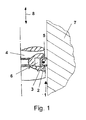
- Figure 1 shows an inventive sealing element 1 in Installed state.
- This shows a sealing ring 2, which housed in a groove 6 of a piston 4 is.
- the piston 4 is oscillating in the direction 8, two sealing lips 9 one above the other Sealing ring 2 are due to the inherent elasticity of the Sealing ring 2 against one arranged around the piston Cylinder wall 7 pressed to seal the Gap between the piston and the cylinder wall.
- the sealing ring 2 has on its radial inside an essentially circumferential receptacle 5 for a Spring element on.
- the sealing ring 2 thus has one "U” shaped cross section. It is about a so-called “U-Flex" design as introduced has been described; for easier recognition the U-shape is hatched throughout in Figure 1. More details on the exact design of the U-Flex sealing ring are e.g. in Figures 2a to 3b given.
- the sealing ring 2 has due to its circumference distributed slots or cross-sectional weakening a very low torsional rigidity in the circumferential direction on. This lack of torsional rigidity is due to the assembly of the sealing ring 2 is disadvantageous because of Sealing ring during assembly in the groove 6 of the piston 4 does not maintain its ring shape by itself. thats why a spring element is provided for support during assembly, which is designated by the reference number 3 in FIG is. It is a wire made of steel with a round cross-section. The spring element 3 is essentially only in one spatial direction (i.e.
- the extension of the Sealing ring 2 in the direction 8 is 2.5 mm in the present case.
- the diameter of the spring element 3 is here 1.0 mm, steel has been chosen as the material.
- the wire diameter depends on the selected one Materials and especially according to the scope of the Sealing ring 2, with a round cross-section, this is between 0.3 and 3 mm, preferably between 0.7 and 2 mm.
- the sealing ring can also be selected from materials other than steel. Here come almost any metallic materials or plastics are also considered (see above).
- the sealing ring 2 has an example in its installed position an outer diameter of 70 mm. However, it is how already mentioned above, also other outside diameters possible between 20 and 200 mm, preferably between 60 and 140 mm.
- the spring element 3, which in the receptacle 5 in Figure 1 essentially all-round and round has a greater curvature at its ends than in the other areas (i.e. in the areas in which one corresponds to the sealing ring in the installed position round curvature is given).
- This "omega shape" has the advantage of snagging the ends is avoided.
- FIG 2a a plan view is shown, which shows that in the area of the radial inner edge of the Sealing ring 2 is given a tooth-like structure. This weakening of the cross-section achieves that stripped oil through appropriate drainage openings drain in the piston into the crankcase can.
- the sealing ring has the advantage that it runs all the way around a good pressure on a surrounding cylinder wall 7 is given and thus a good wiping effect or sealing in the annular space between Piston 4 and cylinder wall 7 is reached.
- FIG. 2b shows a section through the sealing ring Figure 2a according to A-A. Here you can see that it is this is a "U-Flex" sealing ring. The Legs of the "U” represent sealing lips 9.
- FIG. 2 c shows a view F of the sealing ring 2 Figure 2a. Here you can see how several spaced apart Column distributed over the circumference of the sealing ring 2 are.
- FIGS. 2a to 2c shown sealing ring 2 around one, which in Cross section has a "U" shape and over the circumference distributed slots and a radial gap for easier expansion and assembly of the sealing ring a piston groove 6.
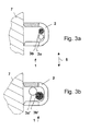
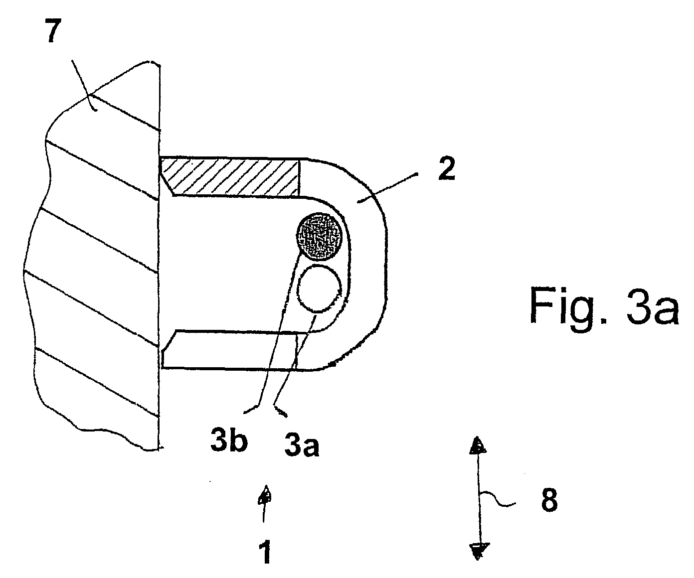
- Figures 3a and 3b show further detail sections of a Sealing rings 2 with inserted spring element 3.
- the spring element is 3rd longer than a circumference of the sealing element 2 in the built-in Status. That is, sections of the spring element 3 each in a partial area of the circumference overlap.
Landscapes
- Engineering & Computer Science (AREA)
- General Engineering & Computer Science (AREA)
- Mechanical Engineering (AREA)
- Pistons, Piston Rings, And Cylinders (AREA)
- Sealing Devices (AREA)
- Glass Compositions (AREA)
- Burglar Alarm Systems (AREA)
- Soy Sauces And Products Related Thereto (AREA)
- Piezo-Electric Or Mechanical Vibrators, Or Delay Or Filter Circuits (AREA)
- Flanged Joints, Insulating Joints, And Other Joints (AREA)
Abstract
Description
- Figur 1
- ein erfindungsgemäßes Dichtelement im Einbauzustand;
- Figur 2a bis 2c
- verschiedene Ansichten eines erfindungsgemäßen Dichtringes;
- Figuren 3a und 3b
- Details eines erfindungsgemäßen Dichtelementes.
Claims (9)
- Dichtelement (1) mit einem Federelement (3) und einem Dichtring (2) mit einer Aufnahme (5) für das Federelement zur Stützung des Dichtrings, dadurch gekennzeichnet, dass das Federelement als im wesentlichen nur in einer Raumrichtung gekrümmtes bogenförmiges Element ausgeführt ist, welches sich über einen Umfangsbereich von mehr als 360° im Einbauzustand des Dichtrings (2) erstreckt.
- Dichtelement nach Anspruch 1, dadurch gekennzeichnet, dass das Federelement (3) im Querschnitt rund, rechteckig oder kreuzförmig oder oval ist.
- Dichtelement nach einem der vorhergehenden Ansprüche, dadurch gekennzeichnet, dass das Federelement (3) bei rundem Querschnitt einen Durchmesser zwischen 0,3 mm und 3 mm, vorzugsweise zwischen 0,7 mm und 2 mm, aufweist und bei anderen Drahtquerschnitten entsprechende Querschnittsflächen aufweist.
- Dichtelement nach einem der vorhergehenden Ansprüche, dadurch gekennzeichnet, dass das Federelement (3) sich über einen Umfangsbereich bis zu 450 Grad im Einbauzustand des Dichtringes (2) erstreckt.
- Dichtelement nach einem der vorhergehenden Ansprüche, dadurch gekennzeichnet, dass in einem Überlappbereich zweier Abschnitte des Federelements (3a, 3b); 3a', 3b') die sich überlappenden Abschnitte bezüglich einer den Dichtring (2) umschließenden Zylinderwand (7) denselben Abstand haben (Fig. 3a) oder gegeneinander versetzt sind (siehe Fig. 3b).
- Dichtelement nach einem der vorhergehenden Ansprüche, dadurch gekennzeichnet, dass das Federelement (3) an seinen Enden eine stärkere Krümmung als in den übrigen Bereichen aufweist.
- Dichtelement nach einem der vorhergehenden Ansprüche, dadurch gekennzeichnet, dass das Federelement aus einem metallischen Werkstoff oder einem Kunststoff ist.
- Dichtelement nach einem der vorhergehenden Ansprüche, dadurch gekennzeichnet, dass der Dichtring (2) im Querschnitt eine U-Form hat und über den Umfang verteilte Schlitze sowie einen radialen Spalt zur leichteren Aufdehnung des Dichtringes aufweist.
- Dichtelement nach einem der vorhergehenden Ansprüche, dadurch gekennzeichnet, dass der Außendurchmesser des Dichtrings (2) in Einbaulage 20 mm - 200 mm, vorzugsweise 60 mm - 120 mm beträgt.
Applications Claiming Priority (2)
| Application Number | Priority Date | Filing Date | Title |
|---|---|---|---|
| DE10225460 | 2002-06-05 | ||
| DE10225460A DE10225460A1 (de) | 2002-06-05 | 2002-06-05 | Dichtelement |
Publications (3)
| Publication Number | Publication Date |
|---|---|
| EP1369626A2 true EP1369626A2 (de) | 2003-12-10 |
| EP1369626A3 EP1369626A3 (de) | 2004-02-11 |
| EP1369626B1 EP1369626B1 (de) | 2006-08-30 |
Family
ID=29432704
Family Applications (1)
| Application Number | Title | Priority Date | Filing Date |
|---|---|---|---|
| EP03090170A Expired - Lifetime EP1369626B1 (de) | 2002-06-05 | 2003-06-05 | Dichtelement |
Country Status (3)
| Country | Link |
|---|---|
| EP (1) | EP1369626B1 (de) |
| AT (1) | ATE338232T1 (de) |
| DE (2) | DE10225460A1 (de) |
Cited By (3)
| Publication number | Priority date | Publication date | Assignee | Title |
|---|---|---|---|---|
| DE102007057956A1 (de) | 2007-12-01 | 2009-06-04 | Mahle International Gmbh | Verfahren zur Herstellung eines Kolbenrings sowie Kolbenring |
| DE102007057959A1 (de) | 2007-12-01 | 2009-06-04 | Mahle International Gmbh | Kolbenring für einen Verbrennungsmotor sowie Kolben mit einem derartigen Kolbenring |
| DE102007057958A1 (de) | 2007-12-01 | 2009-06-04 | Mahle International Gmbh | Verfahren zur Herstellung eines Kolbenrings sowie Kolbenring |
Families Citing this family (1)
| Publication number | Priority date | Publication date | Assignee | Title |
|---|---|---|---|---|
| BR102012028094B8 (pt) * | 2012-10-31 | 2021-03-23 | Mahle Int Gmbh | anel de controle de óleo em peça única |
Family Cites Families (12)
| Publication number | Priority date | Publication date | Assignee | Title |
|---|---|---|---|---|
| DE642606C (de) * | 1937-03-10 | Ernest Arthur Hardy | Geschlitzter Kolbenring mit einer in der inneren Mantelflaeche des Kolbenringes vor-gesehenen Nut und einer in der Nut angeordneten, den Ring ausspreizenden Feder | |
| US1342380A (en) * | 1919-02-26 | 1920-06-01 | Herman C Stifel | Piston-ring |
| US1392614A (en) * | 1919-08-12 | 1921-10-04 | Anderson Per August | Piston-ring |
| US1475680A (en) * | 1922-02-06 | 1923-11-27 | Stephen F Borkey | Piston ring |
| US1666966A (en) * | 1927-06-03 | 1928-04-24 | Frederic X Knobel | Piston and piston-ring construction |
| GB404102A (en) * | 1932-10-05 | 1934-01-11 | Wilfrid Stephen Carlisle | Improvements in or relating to piston rings |
| DE1232420B (de) * | 1962-06-27 | 1967-01-12 | Mcquay Norris Mfg Co | Kolbenringanordnung |
| US3269739A (en) * | 1963-07-01 | 1966-08-30 | Harry M Bramberry | Piston ring construction |
| GB1123332A (en) * | 1966-01-07 | 1968-08-14 | Wellworthy Ltd | Improvements in or relating to piston rings |
| DE19808483C2 (de) * | 1998-02-27 | 1999-12-16 | Federal Mogul Burscheid Gmbh | Ölabstreifkolbenring |
| DE19808484C1 (de) * | 1998-02-27 | 1999-04-29 | Federal Mogul Burscheid Gmbh | Ölabstreifkolbenring |
| DE19808481C1 (de) * | 1998-02-27 | 1999-12-30 | Federal Mogul Burscheid Gmbh | Ölabstreifkolbenring |
-
2002
- 2002-06-05 DE DE10225460A patent/DE10225460A1/de not_active Ceased
-
2003
- 2003-06-05 EP EP03090170A patent/EP1369626B1/de not_active Expired - Lifetime
- 2003-06-05 DE DE50304817T patent/DE50304817D1/de not_active Expired - Fee Related
- 2003-06-05 AT AT03090170T patent/ATE338232T1/de not_active IP Right Cessation
Cited By (3)
| Publication number | Priority date | Publication date | Assignee | Title |
|---|---|---|---|---|
| DE102007057956A1 (de) | 2007-12-01 | 2009-06-04 | Mahle International Gmbh | Verfahren zur Herstellung eines Kolbenrings sowie Kolbenring |
| DE102007057959A1 (de) | 2007-12-01 | 2009-06-04 | Mahle International Gmbh | Kolbenring für einen Verbrennungsmotor sowie Kolben mit einem derartigen Kolbenring |
| DE102007057958A1 (de) | 2007-12-01 | 2009-06-04 | Mahle International Gmbh | Verfahren zur Herstellung eines Kolbenrings sowie Kolbenring |
Also Published As
| Publication number | Publication date |
|---|---|
| ATE338232T1 (de) | 2006-09-15 |
| EP1369626A3 (de) | 2004-02-11 |
| EP1369626B1 (de) | 2006-08-30 |
| DE50304817D1 (de) | 2006-10-12 |
| DE10225460A1 (de) | 2003-12-24 |
Similar Documents
| Publication | Publication Date | Title |
|---|---|---|
| EP0563439B1 (de) | Dichtung für eine hin- und hergehende Stange | |
| DE102014221519B4 (de) | Flexibler Schlauch für ein Abgasrohr eines Kraftfahrzeugs | |
| DE69521314T2 (de) | Überlappende rohrverbindung mit einer verbesserten zusammenpressbaren dichtungszone | |
| DE2055881A1 (de) | Ringdichtung | |
| EP2330326B1 (de) | Rohrförmiges Bauteil | |
| DE102013223329A1 (de) | Gasdynamisches Luftlager | |
| DE19739472A1 (de) | Dichtungsanordnung | |
| EP2017508B1 (de) | Dichtungsanordnung und Verfahren zum Abdichten eines Zwischenraums sowie Bauteilgruppe zum Aufnehmen einer Dichtung | |
| EP2962022B1 (de) | Überströmventil | |
| EP1241388B1 (de) | Elastisch verformbarer Membranbalg sowie ein Verfahren zur Herstellung eines solchen elastisch verformbaren Membranbalgs | |
| EP3850260B1 (de) | Anschlussvorrichtung für rohrleitungen mit leckageanzeige | |
| EP1369626A2 (de) | Dichtelement | |
| EP2519747B1 (de) | Führungseinrichtung für einen metallbalg | |
| EP3797232B1 (de) | Mehrteiliger ölabstreif-kolbenring mit verringerter reibung | |
| EP2899392B1 (de) | Nach dem Feder-Masse-Prinzip arbeitender Schwingungstilger | |
| WO2021068018A1 (de) | Längenverstellbares pleuel mit einer dichtungsvorrichtung | |
| DE10329433B4 (de) | Lageranordnung mit einem Lagerträger und wenigstens einem Lager | |
| DE102015003140A1 (de) | Kolbenspeicher | |
| DE102014209577A1 (de) | Kolbenring mit innenseitiger Profilierung in Umfangsrichtung | |
| DE102017113250A1 (de) | Kolben für eine Pleuelstange und Pleuelstange | |
| EP2483579B1 (de) | Ölabstreifring | |
| EP1985388A1 (de) | Hochdruckfester Metallbalg und Verfahren zum Herstellen eines solchen | |
| DE3638728C2 (de) | ||
| EP3772603B1 (de) | Kolbensicherungsring | |
| AT8703U1 (de) | Dämpfungsvorrichtung für bewegliche möbelteile |
Legal Events
| Date | Code | Title | Description |
|---|---|---|---|
| PUAI | Public reference made under article 153(3) epc to a published international application that has entered the european phase |
Free format text: ORIGINAL CODE: 0009012 |
|
| AK | Designated contracting states |
Kind code of ref document: A2 Designated state(s): AT BE BG CH CY CZ DE DK EE ES FI FR GB GR HU IE IT LI LU MC NL PT RO SE SI SK TR |
|
| AX | Request for extension of the european patent |
Extension state: AL LT LV MK |
|
| PUAL | Search report despatched |
Free format text: ORIGINAL CODE: 0009013 |
|
| AK | Designated contracting states |
Kind code of ref document: A3 Designated state(s): AT BE BG CH CY CZ DE DK EE ES FI FR GB GR HU IE IT LI LU MC NL PT RO SE SI SK TR |
|
| AX | Request for extension of the european patent |
Extension state: AL LT LV MK |
|
| RIC1 | Information provided on ipc code assigned before grant |
Ipc: 7F 16J 9/20 A Ipc: 7F 16J 9/06 B |
|
| 17P | Request for examination filed |
Effective date: 20040806 |
|
| AKX | Designation fees paid |
Designated state(s): AT BE BG CH CY CZ DE DK EE ES FI FR GB GR HU IE IT LI LU MC NL PT RO SE SI SK TR |
|
| GRAP | Despatch of communication of intention to grant a patent |
Free format text: ORIGINAL CODE: EPIDOSNIGR1 |
|
| GRAS | Grant fee paid |
Free format text: ORIGINAL CODE: EPIDOSNIGR3 |
|
| GRAA | (expected) grant |
Free format text: ORIGINAL CODE: 0009210 |
|
| AK | Designated contracting states |
Kind code of ref document: B1 Designated state(s): AT BE BG CH CY CZ DE DK EE ES FI FR GB GR HU IE IT LI LU MC NL PT RO SE SI SK TR |
|
| PG25 | Lapsed in a contracting state [announced via postgrant information from national office to epo] |
Ref country code: NL Free format text: LAPSE BECAUSE OF FAILURE TO SUBMIT A TRANSLATION OF THE DESCRIPTION OR TO PAY THE FEE WITHIN THE PRESCRIBED TIME-LIMIT Effective date: 20060830 Ref country code: IT Free format text: LAPSE BECAUSE OF FAILURE TO SUBMIT A TRANSLATION OF THE DESCRIPTION OR TO PAY THE FEE WITHIN THE PRESCRIBED TIME-LIMIT;WARNING: LAPSES OF ITALIAN PATENTS WITH EFFECTIVE DATE BEFORE 2007 MAY HAVE OCCURRED AT ANY TIME BEFORE 2007. THE CORRECT EFFECTIVE DATE MAY BE DIFFERENT FROM THE ONE RECORDED. Effective date: 20060830 Ref country code: FI Free format text: LAPSE BECAUSE OF FAILURE TO SUBMIT A TRANSLATION OF THE DESCRIPTION OR TO PAY THE FEE WITHIN THE PRESCRIBED TIME-LIMIT Effective date: 20060830 Ref country code: SK Free format text: LAPSE BECAUSE OF FAILURE TO SUBMIT A TRANSLATION OF THE DESCRIPTION OR TO PAY THE FEE WITHIN THE PRESCRIBED TIME-LIMIT Effective date: 20060830 Ref country code: IE Free format text: LAPSE BECAUSE OF FAILURE TO SUBMIT A TRANSLATION OF THE DESCRIPTION OR TO PAY THE FEE WITHIN THE PRESCRIBED TIME-LIMIT Effective date: 20060830 Ref country code: RO Free format text: LAPSE BECAUSE OF FAILURE TO SUBMIT A TRANSLATION OF THE DESCRIPTION OR TO PAY THE FEE WITHIN THE PRESCRIBED TIME-LIMIT Effective date: 20060830 Ref country code: GB Free format text: LAPSE BECAUSE OF FAILURE TO SUBMIT A TRANSLATION OF THE DESCRIPTION OR TO PAY THE FEE WITHIN THE PRESCRIBED TIME-LIMIT Effective date: 20060830 Ref country code: SI Free format text: LAPSE BECAUSE OF FAILURE TO SUBMIT A TRANSLATION OF THE DESCRIPTION OR TO PAY THE FEE WITHIN THE PRESCRIBED TIME-LIMIT Effective date: 20060830 Ref country code: CZ Free format text: LAPSE BECAUSE OF FAILURE TO SUBMIT A TRANSLATION OF THE DESCRIPTION OR TO PAY THE FEE WITHIN THE PRESCRIBED TIME-LIMIT Effective date: 20060830 |
|
| REG | Reference to a national code |
Ref country code: GB Ref legal event code: FG4D Free format text: NOT ENGLISH |
|
| REG | Reference to a national code |
Ref country code: CH Ref legal event code: EP |
|
| REG | Reference to a national code |
Ref country code: IE Ref legal event code: FG4D Free format text: LANGUAGE OF EP DOCUMENT: GERMAN |
|
| REF | Corresponds to: |
Ref document number: 50304817 Country of ref document: DE Date of ref document: 20061012 Kind code of ref document: P |
|
| PG25 | Lapsed in a contracting state [announced via postgrant information from national office to epo] |
Ref country code: BG Free format text: LAPSE BECAUSE OF FAILURE TO SUBMIT A TRANSLATION OF THE DESCRIPTION OR TO PAY THE FEE WITHIN THE PRESCRIBED TIME-LIMIT Effective date: 20061130 Ref country code: SE Free format text: LAPSE BECAUSE OF FAILURE TO SUBMIT A TRANSLATION OF THE DESCRIPTION OR TO PAY THE FEE WITHIN THE PRESCRIBED TIME-LIMIT Effective date: 20061130 Ref country code: DK Free format text: LAPSE BECAUSE OF FAILURE TO SUBMIT A TRANSLATION OF THE DESCRIPTION OR TO PAY THE FEE WITHIN THE PRESCRIBED TIME-LIMIT Effective date: 20061130 |
|
| PG25 | Lapsed in a contracting state [announced via postgrant information from national office to epo] |
Ref country code: ES Free format text: LAPSE BECAUSE OF FAILURE TO SUBMIT A TRANSLATION OF THE DESCRIPTION OR TO PAY THE FEE WITHIN THE PRESCRIBED TIME-LIMIT Effective date: 20061211 |
|
| PG25 | Lapsed in a contracting state [announced via postgrant information from national office to epo] |
Ref country code: PT Free format text: LAPSE BECAUSE OF FAILURE TO SUBMIT A TRANSLATION OF THE DESCRIPTION OR TO PAY THE FEE WITHIN THE PRESCRIBED TIME-LIMIT Effective date: 20070212 |
|
| NLV1 | Nl: lapsed or annulled due to failure to fulfill the requirements of art. 29p and 29m of the patents act | ||
| GBV | Gb: ep patent (uk) treated as always having been void in accordance with gb section 77(7)/1977 [no translation filed] |
Effective date: 20060830 |
|
| ET | Fr: translation filed | ||
| REG | Reference to a national code |
Ref country code: IE Ref legal event code: FD4D |
|
| RAP2 | Party data changed (patent owner data changed or rights of a patent transferred) |
Owner name: DANA HOLDING |
|
| PGFP | Annual fee paid to national office [announced via postgrant information from national office to epo] |
Ref country code: DE Payment date: 20070531 Year of fee payment: 5 |
|
| REG | Reference to a national code |
Ref country code: FR Ref legal event code: TP |
|
| PLBE | No opposition filed within time limit |
Free format text: ORIGINAL CODE: 0009261 |
|
| STAA | Information on the status of an ep patent application or granted ep patent |
Free format text: STATUS: NO OPPOSITION FILED WITHIN TIME LIMIT |
|
| 26N | No opposition filed |
Effective date: 20070531 |
|
| BERE | Be: lapsed |
Owner name: DANA G.M.B.H. Effective date: 20070630 |
|
| PG25 | Lapsed in a contracting state [announced via postgrant information from national office to epo] |
Ref country code: MC Free format text: LAPSE BECAUSE OF NON-PAYMENT OF DUE FEES Effective date: 20070630 |
|
| REG | Reference to a national code |
Ref country code: CH Ref legal event code: PL |
|
| PG25 | Lapsed in a contracting state [announced via postgrant information from national office to epo] |
Ref country code: BE Free format text: LAPSE BECAUSE OF NON-PAYMENT OF DUE FEES Effective date: 20070630 |
|
| PG25 | Lapsed in a contracting state [announced via postgrant information from national office to epo] |
Ref country code: LI Free format text: LAPSE BECAUSE OF NON-PAYMENT OF DUE FEES Effective date: 20070630 Ref country code: CH Free format text: LAPSE BECAUSE OF NON-PAYMENT OF DUE FEES Effective date: 20070630 Ref country code: GR Free format text: LAPSE BECAUSE OF FAILURE TO SUBMIT A TRANSLATION OF THE DESCRIPTION OR TO PAY THE FEE WITHIN THE PRESCRIBED TIME-LIMIT Effective date: 20061201 |
|
| PG25 | Lapsed in a contracting state [announced via postgrant information from national office to epo] |
Ref country code: EE Free format text: LAPSE BECAUSE OF FAILURE TO SUBMIT A TRANSLATION OF THE DESCRIPTION OR TO PAY THE FEE WITHIN THE PRESCRIBED TIME-LIMIT Effective date: 20060830 |
|
| PG25 | Lapsed in a contracting state [announced via postgrant information from national office to epo] |
Ref country code: AT Free format text: LAPSE BECAUSE OF NON-PAYMENT OF DUE FEES Effective date: 20070605 |
|
| PG25 | Lapsed in a contracting state [announced via postgrant information from national office to epo] |
Ref country code: DE Free format text: LAPSE BECAUSE OF NON-PAYMENT OF DUE FEES Effective date: 20090101 |
|
| PG25 | Lapsed in a contracting state [announced via postgrant information from national office to epo] |
Ref country code: LU Free format text: LAPSE BECAUSE OF NON-PAYMENT OF DUE FEES Effective date: 20070605 Ref country code: CY Free format text: LAPSE BECAUSE OF FAILURE TO SUBMIT A TRANSLATION OF THE DESCRIPTION OR TO PAY THE FEE WITHIN THE PRESCRIBED TIME-LIMIT Effective date: 20060830 |
|
| PG25 | Lapsed in a contracting state [announced via postgrant information from national office to epo] |
Ref country code: TR Free format text: LAPSE BECAUSE OF FAILURE TO SUBMIT A TRANSLATION OF THE DESCRIPTION OR TO PAY THE FEE WITHIN THE PRESCRIBED TIME-LIMIT Effective date: 20060830 Ref country code: HU Free format text: LAPSE BECAUSE OF FAILURE TO SUBMIT A TRANSLATION OF THE DESCRIPTION OR TO PAY THE FEE WITHIN THE PRESCRIBED TIME-LIMIT Effective date: 20070301 |
|
| REG | Reference to a national code |
Ref country code: FR Ref legal event code: TP |
|
| REG | Reference to a national code |
Ref country code: FR Ref legal event code: PLFP Year of fee payment: 14 |
|
| REG | Reference to a national code |
Ref country code: FR Ref legal event code: PLFP Year of fee payment: 15 |
|
| REG | Reference to a national code |
Ref country code: FR Ref legal event code: PLFP Year of fee payment: 16 |
|
| PGFP | Annual fee paid to national office [announced via postgrant information from national office to epo] |
Ref country code: FR Payment date: 20180626 Year of fee payment: 16 |
|
| PG25 | Lapsed in a contracting state [announced via postgrant information from national office to epo] |
Ref country code: FR Free format text: LAPSE BECAUSE OF NON-PAYMENT OF DUE FEES Effective date: 20190630 |