EP1369615A2 - Kombiniertes Feder-Dämpfersystem mit Luftfederung - Google Patents
Kombiniertes Feder-Dämpfersystem mit Luftfederung Download PDFInfo
- Publication number
- EP1369615A2 EP1369615A2 EP03009274A EP03009274A EP1369615A2 EP 1369615 A2 EP1369615 A2 EP 1369615A2 EP 03009274 A EP03009274 A EP 03009274A EP 03009274 A EP03009274 A EP 03009274A EP 1369615 A2 EP1369615 A2 EP 1369615A2
- Authority
- EP
- European Patent Office
- Prior art keywords
- spring
- damper system
- bellows
- rolling
- rolling piston
- Prior art date
- Legal status (The legal status is an assumption and is not a legal conclusion. Google has not performed a legal analysis and makes no representation as to the accuracy of the status listed.)
- Withdrawn
Links
- 239000000725 suspension Substances 0.000 title claims abstract description 7
- 238000005096 rolling process Methods 0.000 claims abstract description 55
- 238000013016 damping Methods 0.000 abstract description 6
- 238000010276 construction Methods 0.000 abstract description 3
- 230000036961 partial effect Effects 0.000 abstract description 2
- 238000007789 sealing Methods 0.000 description 12
- 230000002829 reductive effect Effects 0.000 description 7
- 230000008859 change Effects 0.000 description 6
- 239000006096 absorbing agent Substances 0.000 description 2
- 230000002441 reversible effect Effects 0.000 description 2
- 230000035939 shock Effects 0.000 description 2
- 230000007704 transition Effects 0.000 description 2
- 229910000831 Steel Inorganic materials 0.000 description 1
- 230000009471 action Effects 0.000 description 1
- 230000000712 assembly Effects 0.000 description 1
- 238000000429 assembly Methods 0.000 description 1
- 230000002238 attenuated effect Effects 0.000 description 1
- 230000006835 compression Effects 0.000 description 1
- 238000007906 compression Methods 0.000 description 1
- 230000008878 coupling Effects 0.000 description 1
- 238000010168 coupling process Methods 0.000 description 1
- 238000005859 coupling reaction Methods 0.000 description 1
- 230000007423 decrease Effects 0.000 description 1
- 230000003247 decreasing effect Effects 0.000 description 1
- 230000003111 delayed effect Effects 0.000 description 1
- 230000001419 dependent effect Effects 0.000 description 1
- 239000007788 liquid Substances 0.000 description 1
- 238000000034 method Methods 0.000 description 1
- 230000008569 process Effects 0.000 description 1
- 230000003716 rejuvenation Effects 0.000 description 1
- 239000010959 steel Substances 0.000 description 1
Images

Classifications
-
- F—MECHANICAL ENGINEERING; LIGHTING; HEATING; WEAPONS; BLASTING
- F16—ENGINEERING ELEMENTS AND UNITS; GENERAL MEASURES FOR PRODUCING AND MAINTAINING EFFECTIVE FUNCTIONING OF MACHINES OR INSTALLATIONS; THERMAL INSULATION IN GENERAL
- F16F—SPRINGS; SHOCK-ABSORBERS; MEANS FOR DAMPING VIBRATION
- F16F9/00—Springs, vibration-dampers, shock-absorbers, or similarly-constructed movement-dampers using a fluid or the equivalent as damping medium
- F16F9/32—Details
- F16F9/34—Special valve constructions; Shape or construction of throttling passages
-
- F—MECHANICAL ENGINEERING; LIGHTING; HEATING; WEAPONS; BLASTING
- F16—ENGINEERING ELEMENTS AND UNITS; GENERAL MEASURES FOR PRODUCING AND MAINTAINING EFFECTIVE FUNCTIONING OF MACHINES OR INSTALLATIONS; THERMAL INSULATION IN GENERAL
- F16F—SPRINGS; SHOCK-ABSORBERS; MEANS FOR DAMPING VIBRATION
- F16F9/00—Springs, vibration-dampers, shock-absorbers, or similarly-constructed movement-dampers using a fluid or the equivalent as damping medium
- F16F9/02—Springs, vibration-dampers, shock-absorbers, or similarly-constructed movement-dampers using a fluid or the equivalent as damping medium using gas only or vacuum
- F16F9/04—Springs, vibration-dampers, shock-absorbers, or similarly-constructed movement-dampers using a fluid or the equivalent as damping medium using gas only or vacuum in a chamber with a flexible wall
- F16F9/0436—Springs, vibration-dampers, shock-absorbers, or similarly-constructed movement-dampers using a fluid or the equivalent as damping medium using gas only or vacuum in a chamber with a flexible wall characterised by being contained in a generally closed space
-
- F—MECHANICAL ENGINEERING; LIGHTING; HEATING; WEAPONS; BLASTING
- F16—ENGINEERING ELEMENTS AND UNITS; GENERAL MEASURES FOR PRODUCING AND MAINTAINING EFFECTIVE FUNCTIONING OF MACHINES OR INSTALLATIONS; THERMAL INSULATION IN GENERAL
- F16F—SPRINGS; SHOCK-ABSORBERS; MEANS FOR DAMPING VIBRATION
- F16F9/00—Springs, vibration-dampers, shock-absorbers, or similarly-constructed movement-dampers using a fluid or the equivalent as damping medium
- F16F9/02—Springs, vibration-dampers, shock-absorbers, or similarly-constructed movement-dampers using a fluid or the equivalent as damping medium using gas only or vacuum
- F16F9/04—Springs, vibration-dampers, shock-absorbers, or similarly-constructed movement-dampers using a fluid or the equivalent as damping medium using gas only or vacuum in a chamber with a flexible wall
- F16F9/0472—Springs, vibration-dampers, shock-absorbers, or similarly-constructed movement-dampers using a fluid or the equivalent as damping medium using gas only or vacuum in a chamber with a flexible wall characterised by comprising a damping device
-
- F—MECHANICAL ENGINEERING; LIGHTING; HEATING; WEAPONS; BLASTING
- F16—ENGINEERING ELEMENTS AND UNITS; GENERAL MEASURES FOR PRODUCING AND MAINTAINING EFFECTIVE FUNCTIONING OF MACHINES OR INSTALLATIONS; THERMAL INSULATION IN GENERAL
- F16F—SPRINGS; SHOCK-ABSORBERS; MEANS FOR DAMPING VIBRATION
- F16F9/00—Springs, vibration-dampers, shock-absorbers, or similarly-constructed movement-dampers using a fluid or the equivalent as damping medium
- F16F9/02—Springs, vibration-dampers, shock-absorbers, or similarly-constructed movement-dampers using a fluid or the equivalent as damping medium using gas only or vacuum
- F16F9/04—Springs, vibration-dampers, shock-absorbers, or similarly-constructed movement-dampers using a fluid or the equivalent as damping medium using gas only or vacuum in a chamber with a flexible wall
- F16F9/05—Springs, vibration-dampers, shock-absorbers, or similarly-constructed movement-dampers using a fluid or the equivalent as damping medium using gas only or vacuum in a chamber with a flexible wall the flexible wall being of the rolling diaphragm type
Definitions
- the invention relates to a combined spring-damper system with a gas spring for the suspension of wheel suspensions or Axles on a vehicle body with one between a wheel-bearing and / or wheel-guiding connection and a vehicle body-side Connection arranged hose bellows, the arranged between an outer bell and a rolling piston is, on the one hand, the outer bell and the rolling piston respectively over the length of the corresponding component at least partially varying diameter of the hose roll has contacting walls and on the other both ends of the flexible hose on the rolling piston at sections different Diameter are sealingly attached, wherein the rolling piston, the outer bell and the hose roll bellows Form boundaries of a gas-filled Balgraums.
- Combined spring-damper systems are commonly used in bike-leading Struts, e.g. used in McPherson struts. This is usually a steel spring, a hydropneumatic spring or a gas spring with a hydraulic shock absorber combined.
- the present invention is therefore the problem underlying, a combined spring-damper system with a gas spring to develop, which with simple means a low-friction Suspension and damping realized.
- At least one dividing element shares with at least two opposing flow valves the Balgraum in two subspaces.
- the separator is with a connected to each other movable components.
- the bellows space is divided by the separating element into two subspaces divided up.
- the separating element is either with the outer bell or the rolling piston and connected to the other component at least in the longitudinal direction movable.
- the spring rate is determined by the force required is to change a certain spring stroke.
- the damper rate results from the force required for a change the lifting speed.
- the gas in the spring-damper system can be air or any other be suitable gas for this purpose.
- the spring damper system can be connected to a level control his.
- a level control his for example, a pressure source and / or a pressure sink connected to the bellows space.
- a pressure source and / or a pressure sink connected to the bellows space.
- the spring damper system works largely frictionless.
- the Outer bell and the rolling piston are by means of the gas-filled Hose bellows guided.
- the guide length corresponds Here about the length of the hose roll.
- the spring-damper system can also be installed in reverse.
- the forces transmitted by the wheel can be on the outer bell act and the rolling piston on the vehicle body be stored.
- FIG. 1 shows a combined spring-damper system with a displacer (10) acting as an air spring.
- the displacer (10) is u.a. from a multi-level outer bell (30), also a multi-stage rolling piston (40) and connecting both parts, e.g. multipart Differential rolling bellows (11).
- a multi-level outer bell (30) also a multi-stage rolling piston (40) and connecting both parts, e.g. multipart Differential rolling bellows (11).
- the outer wall (23, 24) of the Differenzrollbalgs (11) rolls on the outer bell (30) and on the rolling piston (40).
- the outer bell (30) is a hollow body, the two here at least includes partially cylindrical sections (31, 33), by means of a truncated cone-shaped transition piece (32) are interconnected.
- the upper portion (31) is at its upper End closed with a bottom (34).
- To the ground (34) is an adapter (35) for articulated connection, e.g. by means of a pivot bearing (80), integrally formed on the vehicle body.
- the inner diameter of the upper cylindrical section For example, (31) is one third smaller than the inner diameter of the lower, cylindrical section (33).
- the sections (31) and (33) can also be a frusto-conical Have inner contour. In such a case, the upper section (31) upwards and the lower section (33) taper downwards.
- the rolling piston (40) has an upper (41) and a lower portion (45), wherein both portions (41, 45), for example have a cylindrical outer contour (46, 47).
- Both portions (41, 45) for example have a cylindrical outer contour (46, 47).
- the outer diameter of section (41) is for example about 60% of Inner diameter of the outer bell section (31). The diameter difference is chosen in the embodiment so that respectively the gaps between the opposite ones Sections (31) and (41) in the zones where the menisci (21, 22) of the differential roller (11) move, approximately are the same width.
- the lower portion (45) of the rolling piston tapers (40).
- the rejuvenation begins below the zone, which can be contacted with the differential rolling bellows (11).
- the lower end of the rolling piston (40) ends in an adapter (8) for articulated connection to the chassis (9).
- the between the rolling piston (40) and the outer bell (30) arranged Differenzrollbalg (11) is u.a. from two if necessary identical tubular Rollbalghdonn (12, 13).
- the Rolling-bellows halves (12, 13) are aligned coaxially with each other and about an approximately tubular connecting sleeve (14) gas and liquid tight to each other or on the outer bell (30) attached.
- the connecting sleeve (14) is a short one Pipe, on each side from one side a Rollbalghdon (12, 13) is pushed.
- the deferred section the corresponding Rollbalghdon (12, 13) is on the connecting sleeve (14) by means of a respective clamping ring (17, 18) e.g.
- FIG. 1 has the connection sleeve (14) between the clamping rings (17, 18) a pipe section (15), not from the Rolling bellows halves (12, 13) is covered.
- This pipe section (15) has an outer diameter that is only slightly smaller than the inner diameter of the lower section (33) the outer bell (30).
- a gas (1) e.g. Air filled, whose Pressure, for example, higher than the normal atmospheric pressure is.
- the bellows space (5) is separated by a separating element (50) in two arranged subspaces (6, 7), for example, about divided equally large volume.
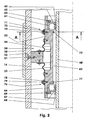
- the separating element (50), cf. Figures 2 and 3, comprises here e.g. an outer (52) and an inner part (53), by means of two bellows (54, 55) to each other movable connected to each other.
- the outer part (52) of the separating element (50) is e.g. on Separating ring (52) sealingly in the coupling sleeve (14) e.g. by means of screws (51) is attached.
- the strength of the Separating ring (52) radially to the connecting sleeve (14) corresponds here e.g. about the length of the separating ring (52) parallel to Axle of the rolling piston (40).
- the inner part (53) of the separating element (50) is e.g. a Separating sleeve (53). This slidably engages the rolling piston (40). Their length corresponds e.g. at least three times Length of the separating ring (52).
- the outer diameter of the Separating sleeve (53) is at least partially smaller than that inner diameter of the separating ring (52), allowing it to mount can be pushed through the separator ring (52) and thereafter over the separating ring (52) above and below.
- a bellows (54, 55) the other end at the top or bottom - So on the front sides - the separating ring (52) is.
- the bellows (54, 55) are gas-tight.
- separating sleeve (53) are further two sealing elements (61, 66), for example, radial sealing rings (61, 66) arranged and e.g. secured axially by retaining rings (64, 69).
- An upper one Radial seal (61) seals the top of the separator sleeve (53) against the rolling piston (40), while the lower Radial sealing ring (66) arranged at the lower end of the separating sleeve (53) is.
- the radial sealing rings (61, 66) limit so together with the separating sleeve (53) and the rolling piston (40) a Transfer room (65).
- Both radial sealing rings (61, 66) are in this case arranged so that their bottom sides (62, 67) after pointing outside and their sealing lips (63, 68) on the rolling piston (40).
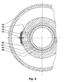
- FIG. 3 which shows the section A-A from FIG.
- the individual spring plate valve (71, 76) comprises, for example, each offset by 30 ° to each other radial bores (72, 77) in the separating sleeve (53), which are closed on the outside of the separating sleeve (53) by a multi-part leaf spring package (73, 78) , These leaf spring assemblies (73, 78) are each fastened to the separating sleeve (53), for example, with a screw (74, 79).
- the spring plate valves (71, 76) other types of flow control valves (71, 76), eg throttle check valves (71, 76) can be used.
- the throttling action of the individual throttle check valve (71, 76) if necessary, be made adjustable by means of a controllable or controllable drive.
- the bellows space (5) - consisting of the subspaces (6) and (7) - may optionally comprise a connection to the outside. About this then the gas pressure in the bellows space (5) can be increased or decreased be used, for example, to regulate the level of vehicle construction.
- the rolling piston (40) is e.g. hollow executed. His interior (44) communicates with the lower one, for example Subspace (7) via the bore (42). The interior (44) acts then as additional volume.
- the rolling piston (40) When compressing a wheel, for example, the rolling piston (40) relative to the outer bell (30) offset upwards.
- the two inner clamping rings (48, 49) of the Hose bladder (11) pulled upwards.
- the lower Hose roll (13) rolls on the outer bell (30) and settles on the rolling piston (40), while the upper Rolling bellows (12) on the rolling piston (40) unrolls and itself on the outer bell (30) applies.
- the volume of the lower subspace (7) is downsized while the volume of the top Subspace (6) is increased.
- the volume of the transfer room (65) remains unchanged.
- the respective gas masses enclosed in the subspaces (6, 7) act as a spring when changing the volume. They build a counterforce on the deformation of the subspaces (6, 7) counteracts.
- the transverse forces acting on the single wheel during driving and the wheel contact forces are transmitted to the chassis. Some of these forces act as a lateral force on the spring damper system, at least when used in a McPherson strut.
- the shear forces act, for example on the rolling piston (40), which is above the hose roll (11) on the gas-filled bellows compartment (5) and on the outer bell (30) is supported.
- the separating sleeve (53) offset relative to the separating ring (52) and partially also pivoted.
- the bellows (54, 55) are deformed, so that no radial forces transmitted via the separating element (50) become.
- the outer bell (30) is thus on the whole Length of the hose rolling bellows (11) guided friction.
- the outer bell (30) can be opposite to the rolling piston (40) despite the intermediate separating element (50) do not tilt.
- the separating element (50) can also be constructed such that its inner part (53) is attached to the rolling piston (40) and its outer part (52) slides along the outer bell (30).
- the attachment of the spring-damper system to the vehicle body can in addition to a pivot joint (80) and a rolling bearing - Pivoting the spring-damper system about its longitudinal axis - or include a joint of other types. Also a combination various joint types is conceivable.
Landscapes
- Engineering & Computer Science (AREA)
- General Engineering & Computer Science (AREA)
- Mechanical Engineering (AREA)
- Vehicle Body Suspensions (AREA)
- Fluid-Damping Devices (AREA)
Abstract
Description
- Figur 1:
- Kombiniertes Feder-Dämpfersystem mit einer Luftfeder und einem Differenzrollbalg;
- Figur 2:
- Detail des Trennelementes;
- Figur 3:
- Schnitt A-A aus Figur 2.
Anstatt der Federplattenventile (71, 76) können auch andere Bauformen von Stromventilen (71, 76), z.B. Drosselrückschlagventile (71, 76) eingesetzt werden. Auch kann hierbei die Drosselwirkung des einzelnen Drosselrückschlagventils (71, 76) ggf. mittels eines steuer- oder regelbaren Antriebs verstellbar ausgeführt werden.
Ein Teil dieser Kräfte wirkt, zumindest bei der Verwendung in einem McPherson-Federbein, als Querkraft auf das Feder-Dämpfersystem.
Claims (10)
- Kombiniertes Feder-Dämpfersystem zur Abstützung von Radaufhängungen oder Achsen an einem Fahrzeugaufbau mit einem zwischen einer radtragenden und/oder radführenden Anbindung und einer fahrzeugaufbauseitigen Anbindung angeordneten Schlauchrollbalg, der zwischen einer Außenglocke und einem Abrollkolben angeordnet ist, wobei zum einen die Außenglocke und der Abrollkolben jeweils über der Länge des entsprechenden Bauteils zumindest bereichsweise variierende Durchmesser der den Schlauchrollbalg kontaktierenden Wandungen hat und zum anderen beide Enden des Schlauchrollbalgs am Abrollkolben an Abschnitten unterschiedlichen Durchmessers abdichtend befestigt sind, wobei der Abrollkolben, die Außenglocke und der Schlauchrollbalg Begrenzungen eines gasbefüllten Balgraums bilden, dadurch gekennzeichnet,dass mindestens ein Trennelement (50) mit mindestens zwei einander gegenläufigen Stromventilen (71, 76) den Balgraum (5) in zwei Teilräume (6, 7) aufteilt unddass das Trennelement (50) mit einem der zueinander beweglichen Bauteile (30, 40) verbunden ist.
- Feder-Dämpfersystem nach Anspruch 1, dadurch gekennzeichnet, dass der Schlauchrollbalg ein mindestens zweiteiliger Differenzrollbalg (11) ist.
- Feder-Dämpfersystem nach Anspruch 1, dadurch gekennzeichnet, dass die Stromventile (71, 76) Federplattenventile (71, 76) sind.
- Feder-Dämpfersystem nach Anspruch 1, dadurch gekennzeichnet, dass der Abrollkolben (40) ein Hohlkolben ist, der mit einem der Teilräume (6, 7) kommuniziert.
- Feder-Dämpfersystem nach Anspruch 1, dadurch gekennzeichnet, dass an das Feder-Dämpfersystem eine Niveauregulierung angeschlossen ist.
- Feder-Dämpfersystem nach Anspruch 1, dadurch gekennzeichnet, dass die Volumina der Teilräume (6, 7) zumindest annähernd gleich groß sind.
- Feder-Dämpfersystem nach Anspruch 1, dadurch gekennzeichnet, dass die Außenglocke (30) radseitig befestigt ist.
- Feder-Dämpfersystem nach Anspruch 1, dadurch gekennzeichnet, dass der Abrollkolben (40) in einem Wälzlager im Fahrzeugaufbau angeordnet ist.
- Feder-Dämpfersystem nach Anspruch 1, dadurch gekennzeichnet, dass das Trennelement (50) einen äußeren (52) und einen inneren Teil (53) umfasst, die gegeneinander beweglich sind, wobei der äußere Teil (52) mit der Außenglocke (30) verbunden ist und der innere Teil (53) auf dem Abrollkolben (40) gleitet.
- Feder-Dämpfersystem nach Anspruch 9, dadurch gekennzeichnet, dass der äußere (52) und der innere Teil (53) mittels mindestens eines Faltenbalgs (54, 55) verbunden sind.
Applications Claiming Priority (2)
| Application Number | Priority Date | Filing Date | Title |
|---|---|---|---|
| DE2002124868 DE10224868B3 (de) | 2002-06-05 | 2002-06-05 | Kombiniertes Feder-Dämpfersystem mit Luftfederung |
| DE10224868 | 2002-06-05 |
Publications (2)
| Publication Number | Publication Date |
|---|---|
| EP1369615A2 true EP1369615A2 (de) | 2003-12-10 |
| EP1369615A3 EP1369615A3 (de) | 2004-09-01 |
Family
ID=29432643
Family Applications (1)
| Application Number | Title | Priority Date | Filing Date |
|---|---|---|---|
| EP03009274A Withdrawn EP1369615A3 (de) | 2002-06-05 | 2003-04-24 | Kombiniertes Feder-Dämpfersystem mit Luftfederung |
Country Status (2)
| Country | Link |
|---|---|
| EP (1) | EP1369615A3 (de) |
| DE (1) | DE10224868B3 (de) |
Cited By (1)
| Publication number | Priority date | Publication date | Assignee | Title |
|---|---|---|---|---|
| CN111873795A (zh) * | 2020-07-24 | 2020-11-03 | 中国重汽集团济南动力有限公司 | 一种商用车传动轴用气囊式中间支承装置、装配方法及使用方法 |
Families Citing this family (2)
| Publication number | Priority date | Publication date | Assignee | Title |
|---|---|---|---|---|
| DE102004059764C5 (de) * | 2004-12-11 | 2013-06-06 | Continental Teves Ag & Co. Ohg | Luftfeder- und Dämpfereinheit |
| US20210062886A1 (en) * | 2019-08-29 | 2021-03-04 | GM Global Technology Operations LLC | Rolling lobe seal for an air spring assembly |
Citations (1)
| Publication number | Priority date | Publication date | Assignee | Title |
|---|---|---|---|---|
| DE2759435C2 (de) | 1977-11-12 | 1982-03-25 | Daimler-Benz Ag, 7000 Stuttgart | Luftfeder für Kraftfahrzeuge |
Family Cites Families (4)
| Publication number | Priority date | Publication date | Assignee | Title |
|---|---|---|---|---|
| DE2750666C3 (de) * | 1977-11-12 | 1980-07-10 | Daimler-Benz Ag, 7000 Stuttgart | Luftfeder, insbesondere für die Abfederung der ungefederten Massen von Fahrzeugen |
| DE2750667C2 (de) * | 1977-11-12 | 1980-01-24 | Daimler-Benz Ag, 7000 Stuttgart | Luftfeder für Kraftfahrzeuge |
| JPH03234938A (ja) * | 1989-08-25 | 1991-10-18 | Bridgestone Corp | 振動減衰装置 |
| ATE349369T1 (de) * | 1998-11-09 | 2007-01-15 | Contitech Luftfedersyst Gmbh | Federungseinrichtung |
-
2002
- 2002-06-05 DE DE2002124868 patent/DE10224868B3/de not_active Expired - Fee Related
-
2003
- 2003-04-24 EP EP03009274A patent/EP1369615A3/de not_active Withdrawn
Patent Citations (1)
| Publication number | Priority date | Publication date | Assignee | Title |
|---|---|---|---|---|
| DE2759435C2 (de) | 1977-11-12 | 1982-03-25 | Daimler-Benz Ag, 7000 Stuttgart | Luftfeder für Kraftfahrzeuge |
Cited By (1)
| Publication number | Priority date | Publication date | Assignee | Title |
|---|---|---|---|---|
| CN111873795A (zh) * | 2020-07-24 | 2020-11-03 | 中国重汽集团济南动力有限公司 | 一种商用车传动轴用气囊式中间支承装置、装配方法及使用方法 |
Also Published As
| Publication number | Publication date |
|---|---|
| EP1369615A3 (de) | 2004-09-01 |
| DE10224868B3 (de) | 2004-03-25 |
Similar Documents
| Publication | Publication Date | Title |
|---|---|---|
| DE3904071C2 (de) | ||
| DE102013215360B4 (de) | Höhenverstellvorrichtung für Fahrzeuge mit Luftfeder und Schwingungsdämpfer | |
| DE112013004595B4 (de) | Aufhängungsvorrichtung | |
| DE102008006476B4 (de) | Gasdruckstoßdämpfer | |
| EP3746676B1 (de) | Schwingungsdämpfer für ein fahrzeug | |
| DE10121918B4 (de) | Feder-Dämpfer-System mit federndem Anschlag | |
| WO2005092646A1 (de) | Gasfedersystem mit zentral geführtem schlauchrollbalg | |
| DE6604159U (de) | Einrohr-teleskopschwingungsdaempfer, insbesondere fuer kraftfahrzeuge | |
| DE3641623C2 (de) | ||
| DE1505522B1 (de) | Hydropneumatischer Einrohr-Teleskopstossdaempfer mit davon unabhaengiger,parallel geschalteter Gasfeder und selbsttaetig steuerbarem Daempfungsgrad,insbesondere fuer Kraftfahrzeuge | |
| EP1206653B1 (de) | Feder-dämpfersystem mit differenzrollbalg | |
| DE102019210972A1 (de) | Integrierte Luftfeder- und Stoßdämpfervorrichtung mit stufenloser Einstellbarkeit | |
| DE112004001835T5 (de) | Design für ein anliegendes Prallteil eines Stoßdämpfers | |
| DE112023000491T5 (de) | Stossdämpfer | |
| DE102006025826B4 (de) | Selbstpumpendes hydropneumatisches Federbein | |
| DE10314621A1 (de) | Pneumatische Feder-Dämpfer-Einheit | |
| WO2019020625A1 (de) | Tragfeder-dämpfer-system eines fahrzeug-rades | |
| DE102004059765A1 (de) | Radführende Luftfeder- und Dämpfereinheit | |
| DE3601445C2 (de) | ||
| DE10224868B3 (de) | Kombiniertes Feder-Dämpfersystem mit Luftfederung | |
| DE10024571B4 (de) | Feder-Dämpfersystem mit Differenzrollbalg | |
| DE10034603A1 (de) | Fahrwerk mit Tilgermassen | |
| DE10024572B4 (de) | Feder-Dämpfersystem mit Doppelrollbalg | |
| DE102010023870A1 (de) | Progressive Gasfederdämpfervorrichtung | |
| DE3817840A1 (de) | Teleskop-stossdaempfer fuer kraftfahrzeuge |
Legal Events
| Date | Code | Title | Description |
|---|---|---|---|
| PUAI | Public reference made under article 153(3) epc to a published international application that has entered the european phase |
Free format text: ORIGINAL CODE: 0009012 |
|
| AK | Designated contracting states |
Kind code of ref document: A2 Designated state(s): AT BE BG CH CY CZ DE DK EE ES FI FR GB GR HU IE IT LI LU MC NL PT RO SE SI SK TR |
|
| AX | Request for extension of the european patent |
Extension state: AL LT LV MK |
|
| PUAL | Search report despatched |
Free format text: ORIGINAL CODE: 0009013 |
|
| AK | Designated contracting states |
Kind code of ref document: A3 Designated state(s): AT BE BG CH CY CZ DE DK EE ES FI FR GB GR HU IE IT LI LU MC NL PT RO SE SI SK TR |
|
| AX | Request for extension of the european patent |
Extension state: AL LT LV MK |
|
| 17P | Request for examination filed |
Effective date: 20040728 |
|
| 17Q | First examination report despatched |
Effective date: 20041208 |
|
| AKX | Designation fees paid |
Designated state(s): DE FR GB IT |
|
| RBV | Designated contracting states (corrected) |
Designated state(s): DE FR GB IT |
|
| GRAP | Despatch of communication of intention to grant a patent |
Free format text: ORIGINAL CODE: EPIDOSNIGR1 |
|
| STAA | Information on the status of an ep patent application or granted ep patent |
Free format text: STATUS: THE APPLICATION IS DEEMED TO BE WITHDRAWN |
|
| 18D | Application deemed to be withdrawn |
Effective date: 20060427 |