EP1369578A2 - Air cleaner and resonator assembly - Google Patents
Air cleaner and resonator assembly Download PDFInfo
- Publication number
- EP1369578A2 EP1369578A2 EP03253450A EP03253450A EP1369578A2 EP 1369578 A2 EP1369578 A2 EP 1369578A2 EP 03253450 A EP03253450 A EP 03253450A EP 03253450 A EP03253450 A EP 03253450A EP 1369578 A2 EP1369578 A2 EP 1369578A2
- Authority
- EP
- European Patent Office
- Prior art keywords
- shell
- resonator
- air
- set forth
- filter
- Prior art date
- Legal status (The legal status is an assumption and is not a legal conclusion. Google has not performed a legal analysis and makes no representation as to the accuracy of the status listed.)
- Granted
Links
- 238000003466 welding Methods 0.000 claims description 13
- 238000000034 method Methods 0.000 claims description 12
- 239000000356 contaminant Substances 0.000 claims description 7
- 230000000644 propagated effect Effects 0.000 claims description 3
- 238000000465 moulding Methods 0.000 claims 2
- 230000006698 induction Effects 0.000 description 14
- 230000002238 attenuated effect Effects 0.000 description 2
- 230000000694 effects Effects 0.000 description 2
- 239000000463 material Substances 0.000 description 2
- 238000002485 combustion reaction Methods 0.000 description 1
- 230000007812 deficiency Effects 0.000 description 1
- 238000010586 diagram Methods 0.000 description 1
- 239000000428 dust Substances 0.000 description 1
- 238000001746 injection moulding Methods 0.000 description 1
- 230000014759 maintenance of location Effects 0.000 description 1
- 230000013011 mating Effects 0.000 description 1
- 238000012986 modification Methods 0.000 description 1
- 230000004048 modification Effects 0.000 description 1
Images

Classifications
-
- F—MECHANICAL ENGINEERING; LIGHTING; HEATING; WEAPONS; BLASTING
- F02—COMBUSTION ENGINES; HOT-GAS OR COMBUSTION-PRODUCT ENGINE PLANTS
- F02M—SUPPLYING COMBUSTION ENGINES IN GENERAL WITH COMBUSTIBLE MIXTURES OR CONSTITUENTS THEREOF
- F02M35/00—Combustion-air cleaners, air intakes, intake silencers, or induction systems specially adapted for, or arranged on, internal-combustion engines
- F02M35/14—Combined air cleaners and silencers
-
- F—MECHANICAL ENGINEERING; LIGHTING; HEATING; WEAPONS; BLASTING
- F02—COMBUSTION ENGINES; HOT-GAS OR COMBUSTION-PRODUCT ENGINE PLANTS
- F02M—SUPPLYING COMBUSTION ENGINES IN GENERAL WITH COMBUSTIBLE MIXTURES OR CONSTITUENTS THEREOF
- F02M35/00—Combustion-air cleaners, air intakes, intake silencers, or induction systems specially adapted for, or arranged on, internal-combustion engines
- F02M35/02—Air cleaners
- F02M35/0212—Multiple cleaners
- F02M35/0215—Multiple cleaners arranged in parallel
-
- F—MECHANICAL ENGINEERING; LIGHTING; HEATING; WEAPONS; BLASTING
- F02—COMBUSTION ENGINES; HOT-GAS OR COMBUSTION-PRODUCT ENGINE PLANTS
- F02M—SUPPLYING COMBUSTION ENGINES IN GENERAL WITH COMBUSTIBLE MIXTURES OR CONSTITUENTS THEREOF
- F02M35/00—Combustion-air cleaners, air intakes, intake silencers, or induction systems specially adapted for, or arranged on, internal-combustion engines
- F02M35/02—Air cleaners
- F02M35/024—Air cleaners using filters, e.g. moistened
- F02M35/02475—Air cleaners using filters, e.g. moistened characterised by the shape of the filter element
- F02M35/02483—Cylindrical, conical, oval, spherical or the like filter elements; wounded filter elements
-
- F—MECHANICAL ENGINEERING; LIGHTING; HEATING; WEAPONS; BLASTING
- F02—COMBUSTION ENGINES; HOT-GAS OR COMBUSTION-PRODUCT ENGINE PLANTS
- F02M—SUPPLYING COMBUSTION ENGINES IN GENERAL WITH COMBUSTIBLE MIXTURES OR CONSTITUENTS THEREOF
- F02M35/00—Combustion-air cleaners, air intakes, intake silencers, or induction systems specially adapted for, or arranged on, internal-combustion engines
- F02M35/12—Intake silencers ; Sound modulation, transmission or amplification
- F02M35/1205—Flow throttling or guiding
- F02M35/1227—Flow throttling or guiding by using multiple air intake flow paths, e.g. bypass, honeycomb or pipes opening into an expansion chamber
-
- F—MECHANICAL ENGINEERING; LIGHTING; HEATING; WEAPONS; BLASTING
- F02—COMBUSTION ENGINES; HOT-GAS OR COMBUSTION-PRODUCT ENGINE PLANTS
- F02M—SUPPLYING COMBUSTION ENGINES IN GENERAL WITH COMBUSTIBLE MIXTURES OR CONSTITUENTS THEREOF
- F02M35/00—Combustion-air cleaners, air intakes, intake silencers, or induction systems specially adapted for, or arranged on, internal-combustion engines
- F02M35/12—Intake silencers ; Sound modulation, transmission or amplification
- F02M35/1255—Intake silencers ; Sound modulation, transmission or amplification using resonance
Definitions
- This invention is directed to an engine air cleaner which also serves to attenuate engine noise.
- Air induction systems are used to conduct air to internal combustion engines.
- the use of air induction systems has resulted in the need for additional vehicle system components to compensate for certain undesirable side effects generated by the connection of air induction components to the vehicle engine. For example, engine noise is propagated back through the air induction components, which is undesirable.
- noise attenuation components such as resonators, have been utilised to reduce these noises.
- air induction components Another undesirable side effect introduced by air induction components, is that the air that is drawn into the air induction system includes dust, dirt, and other particulate contaminants. These contaminants can clog the engine resulting in poor performance. Air cleaners with filters are used to remove these contaminants from the airflow prior to the air being drawn into the engine.
- the subject method and apparatus provides an air induction system that includes a unitary air cleaner and resonator assembly.
- Figure 1 is a schematic diagram of an engine and induction system incorporating the subject invention.
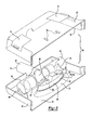
- Figure 2 is an exploded view of the subject resonator and air filter assembly.
- Figure 3 is a partial exploded view of the resonator and air filter assembly of Figure 1 showing middle and lower shell portions attached together.
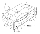
- Figure 4 is a perspective view of the resonator and air filter assembly of Figure 2 showing the upper, middle, and lower shell portions attached together.
- An air cleaner and resonator assembly is formed from a plurality of air cleaner shells or housing portions that are joined together. According to an aspect of the present invention, a lower portion of a resonator is formed within one of the housing portions and an upper portion of the resonator is formed within another of the housing portions. The upper and lower portions of the resonator are then joined together to form a sealed resonator chamber that is positioned within the air cleaner.
- the air cleaner and resonator assembly thus forms a unitary structure that simultaneously attenuates engine noise and filters contaminants from the air.
- the air cleaner and resonator assembly is formed from a lower shell and an upper shell that are joined together to define an interior cavity having an inlet through which air is drawn.
- An outlet portion formed within the lower shell, directs air from the inlet to the engine.
- a middle shell is positioned within the inner cavity and is joined to both the upper and lower shells.
- a lower portion of a resonator is moulded into the lower shell and an upper portion of the resonator assembly is moulded into the middle shell.
- the upper portion is aligned with the lower portion and the middle and lower shells are welded together to form a sealed resonator chamber that attenuates engine noise.
- the upper and lower shell portions are then welded together to form the air cleaner and resonator assembly.
- a portion of the upper shell is also preferably welded to the middle shell to increase strength and stiffness.
- Air filters may be installed within the interior cavity and may be selectively accessible through movable covers installed in the upper shell portion.
- the air filters are mounted on tube mounts moulded into the middle shell portion and rest on cradle mounts formed on the lower shell portion.
- the outlet portion may comprise an exit tube moulded into the lower shell.
- a lower neck portion is also moulded into the lower shell with a corresponding upper neck portion being moulded into the middle shell.
- the upper and lower neck portions may be aligned and joined within one another to form a neck that interconnects the exit tube to the resonator.
- a method for forming the air cleaner and resonator assembly includes the following steps.
- the lower shell is formed with a lower resonator portion and the middle shell is formed with an upper resonator portion.
- the middle shell is welded to the lower shell to form a sealed resonator chamber that attenuates engine noise. This welding operation forms a first weld joint between the middle and lower shells. Additional optional steps include welding the upper shell to the lower shell to form a second weld joint and welding the upper shell to the middle shell to form a third weld joint.
- an induction system 10 draws air 12 into a vehicle engine 14.
- the induction system 10 includes a resonator and air filter assembly, shown generally at 16.
- the resonator and air filter assembly 16 is shown in greater detail in Figure 2.
- the resonator and air filter assembly 16 includes a lower shell 18, a middle shell 20, and an upper shell 22.
- the lower shell 18 includes a lower mouth portion 24 that forms an air inlet 26, and an exit tube 28 that forms an air outlet 30 to the engine 14.
- the lower shell 18 also includes a lower resonator portion 32 and a lower neck portion 34 that interconnects the lower resonator portion 32 to the exit tube 28.
- the middle shell 20 includes an upper resonator portion 36, an upper neck portion 38, and a pair of air filter mounting tubes 40.
- the middle shell 20 also includes a small upper portion 42 that forms a portion of the exit tube 28.
- the exit tube 28 and upper neck portion 38 extend in a generally longitudinal direction while the air filter mounting tubes 40 extend outwardly from the upper neck portion 38 in opposing directions from each other and in a generally lateral direction that is transverse to the longitudinal direction.
- a first attachment interface 44 is formed about an upper edge of the lower shell 18.
- the first attachment interface 44 includes a first interface portion 44a that extends along upper edges of the lower resonator portion 32 and the lower neck portion 34, and a second interface portion 44b that is formed about the upper perimeter of the lower shell 18.
- a resonator attachment interface 46 is formed about the lower edge of the middle shell 20.
- the resonator attachment interface 46 extends around the bottom edge face of the upper resonator portion 36 and the bottom face of the upper neck portion 38.
- the first interface portion 44a and the resonator attachment interface 46 are aligned with and positioned in abutting engagement with each other. Once the attachment interfaces 44a, 46 are aligned properly, the middle 20 and lower 18 shells are attached together.
- the first interface portion 44a and the resonator attachment interface 46 are welded together by vibration welding, hot plate welding, or other similar welding process known in the art.
- a weld joint is formed between the middle 20 and lower 18 shells to provide a secure and permanent attachment.
- the lower 32 and upper 36 resonator portions co-operate to form a sealed resonance chamber 50, see Figure 3.
- the resonance chamber 50 attenuates engine noise that is propagated back through the induction system 10.
- the upper shell 22 includes an upper mouth portion 52 that forms part of the air inlet 26.
- the upper 52 and lower 24 mouth portions co-operate to form a bell shaped mouth.
- the bell-shaped feature formed about the perimeter of the air inlet minimises inlet airflow pressure losses.
- the upper shell 22 defines a second attachment interface 54 that extends about the lower edge.
- the third attachment interface 54 is positioned in an overlapping relationship to the second attachment interface portion 44b of the lower shell 18.
- the shells 22, 18 are attached together to enclose the resonator chamber 50 within the induction system 10.
- the second interface portion 44b and third attachment interface 54 are welded together by vibration welding, hot-plate welding, or other similar welding process known in the art.
- a weld joint is formed between the upper 22 and lower 18 shells to provide a secure and permanent attachment.
- the upper. shell 22 includes a first plurality of joining areas 56 formed on a lower surface 58 of the upper shell 22 that correspond to a second plurality of joining areas 60 formed on an upper surface 62 of the middle shell 20.
- the first 56 and second 60 pluralities of joining areas are aligned with each other and are welded together, as i discussed above.
- the induction system 10 also includes air filters 64 that filter contaminant particulates that are drawn in through the air inlet 26.
- Cradles 66 are formed on the lower shell 18 to support one end 68 of each filter 64.
- Opposite ends 70 of the filters 64 are mated with the air filter mounting tubes 40 formed on the middle shell 20.
- Openings 72 are formed in the upper shell 22 to facilitate access to the filters 64 for service and/or replacement.
- Doors 74 are snap-fit, or similarly installed, to cover the openings 72 during vehicle operation.
- Upper cradles 76 can be formed on the bottom surface of the doors 74 to provide additional support for the filters 64.
- the lower shell 18, middle shell 20, and upper shell 22 are formed from a plastic material in an injection moulding process.
- the upper 22 and lower 18 shells are joined together during the welding process along the interfaces 44b, 54 to create an outer housing 78, see Figure 4, of an air cleaner that has a generally rectangular air inlet 26 with a curved bell mouth feature 80.
- exit tube 28, lower neck portion 34, and lower resonator portion 32 are preferably integrally moulded within the lower shell 18.
- the upper resonator portion 36, upper neck portion 38, and filter mounting tubes 40 are all preferably moulded within the middle shell 20.
- the middle shell 20 is welded to the lower shell 18 along attachment interface 46 onto the mating attachment interface 44a on the lower shell 18. This creates the resonance chamber 50, a neck 82, and filter mounting tube 40.
- the upper 22 and lower 18 shells are welded together as described above.
- the first 56 and second 60 plurality of joining areas are welded together to join the upper shell 22 to the middle shell 20.
- this attachment is formed at the resonator portions to create more strength and stiffness in the structure.
- the air filters 64 are mounted to the attachment mounting tubes 40 on each side of the neck 82. Access to install and service the filters 64 is through the doors 74 that are positioned over the filters 64. Positioning and further retention of the filters 64 is achieved by the lower cradles 66 and the upper cradles 76. Preferably, the cradles 66, 76 are crescent-shaped ribs. The doors 74 are snapped into place and locate and retain each filter 64 vertically.
- the air is drawn through the inlet 26 to either side of the resonance chamber 50 and enters the open space formed between the upper 22 and lower 18 shells.
- the air then flows into each respective air filter 64 and into the neck 62 via the mounting tubes 40.
- the air flows out of the exit tube 28 to the engine 14. Noise from the engine proceeds in an opposite direction from the airflow and is partially attenuated by the resonator 50.
- an air cleaner assembly comprises: a lower shell having a lower air inlet portion and an air outlet for directing air to a vehicle engine, said lower shell defining a first attachment interface formed substantially about an upper edge of said lower shell; an upper shell having an upper inlet portion aligned with said lower air inlet portion to form an air inlet, said upper shell defining a second attachment interface formed substantially about a lower edge of said upper shell that co-operates with said first attachment interface to secure said upper shell to said lower shell; at least one air filter mounted between said upper and lower shells to remove contaminants from the air as the air flows from said inlet to said outlet; a middle shell positioned between said upper and lower shells and defining a third attachment interface formed substantially about a lower edge of said middle shell; and a resonator having a lower resonator portion formed within said lower shell and an upper resonator portion formed within said middle shell, said resonator defining a fourth attachment interface formed substantially about an upper edge of said lower resonator portion wherein said
- the third attachment interface may abut against said fourth attachment interface to form a first weld joint and said second attachment interface may abut against said first attachment interface to form a second weld joint.
- the middle shell may include a fifth attachment interface formed on an upper surface of said middle shell; and the upper shell may include a sixth attachment interface formed on a lower surface of said upper shell.
- the fifth and sixth attachment interfaces may abut against each other to form a weld joint.
- the lower resonator portion may be integrally formed with said lower shell as one piece.
- the upper resonator portion may be integrally formed with said middle shell as one piece.
- the outlet may comprise an exit tube integrally formed with said lower shell as one piece.
Abstract
Description
- This invention is directed to an engine air cleaner which also serves to attenuate engine noise.
- Air induction systems are used to conduct air to internal combustion engines. The use of air induction systems has resulted in the need for additional vehicle system components to compensate for certain undesirable side effects generated by the connection of air induction components to the vehicle engine. For example, engine noise is propagated back through the air induction components, which is undesirable. To address this problem, noise attenuation components, such as resonators, have been utilised to reduce these noises.
- Another undesirable side effect introduced by air induction components, is that the air that is drawn into the air induction system includes dust, dirt, and other particulate contaminants. These contaminants can clog the engine resulting in poor performance. Air cleaners with filters are used to remove these contaminants from the airflow prior to the air being drawn into the engine.
- The use of these additional components such as the resonator and air cleaner increases material and overall system costs. Further, the assembly of the additional components into the air induction system is time consuming and labour intensive. Thus, it is the object of the present invention to provide a simplified air cleaner and resonator assembly that reduces the overall number of required components, and which can be easily assembled, as well as overcoming the other above-mentioned deficiencies with the prior art.
- The present invention accordingly provides apparatus and methods as defined in the appended claims.
- The subject method and apparatus provides an air induction system that includes a unitary air cleaner and resonator assembly. These and other features of the present invention can be best understood from the following specifications and drawings, the following of which is a brief description.
- Figure 1 is a schematic diagram of an engine and induction system incorporating the subject invention.
- Figure 2 is an exploded view of the subject resonator and air filter assembly.
- Figure 3 is a partial exploded view of the resonator and air filter assembly of Figure 1 showing middle and lower shell portions attached together.
- Figure 4 is a perspective view of the resonator and air filter assembly of Figure 2 showing the upper, middle, and lower shell portions attached together.
- An air cleaner and resonator assembly is formed from a plurality of air cleaner shells or housing portions that are joined together. According to an aspect of the present invention, a lower portion of a resonator is formed within one of the housing portions and an upper portion of the resonator is formed within another of the housing portions. The upper and lower portions of the resonator are then joined together to form a sealed resonator chamber that is positioned within the air cleaner. The air cleaner and resonator assembly thus forms a unitary structure that simultaneously attenuates engine noise and filters contaminants from the air.
- In one embodiment, the air cleaner and resonator assembly is formed from a lower shell and an upper shell that are joined together to define an interior cavity having an inlet through which air is drawn. An outlet portion, formed within the lower shell, directs air from the inlet to the engine. A middle shell is positioned within the inner cavity and is joined to both the upper and lower shells. A lower portion of a resonator is moulded into the lower shell and an upper portion of the resonator assembly is moulded into the middle shell. The upper portion is aligned with the lower portion and the middle and lower shells are welded together to form a sealed resonator chamber that attenuates engine noise. The upper and lower shell portions are then welded together to form the air cleaner and resonator assembly. A portion of the upper shell is also preferably welded to the middle shell to increase strength and stiffness.
- Air filters may be installed within the interior cavity and may be selectively accessible through movable covers installed in the upper shell portion. The air filters are mounted on tube mounts moulded into the middle shell portion and rest on cradle mounts formed on the lower shell portion.
- The outlet portion may comprise an exit tube moulded into the lower shell. A lower neck portion is also moulded into the lower shell with a corresponding upper neck portion being moulded into the middle shell. The upper and lower neck portions may be aligned and joined within one another to form a neck that interconnects the exit tube to the resonator. Air flows into the inlet, through the filters and into the exit tube via the tube mounts. Clean air then flows in a first direction within the exit tube toward the engine. Noise from the engine proceeds in a second direction, opposite from the first direction, and is attenuated by the resonator.
- A method for forming the air cleaner and resonator assembly includes the following steps. The lower shell is formed with a lower resonator portion and the middle shell is formed with an upper resonator portion. The middle shell is welded to the lower shell to form a sealed resonator chamber that attenuates engine noise. This welding operation forms a first weld joint between the middle and lower shells. Additional optional steps include welding the upper shell to the lower shell to form a second weld joint and welding the upper shell to the middle shell to form a third weld joint.
- As shown in Figure 1, an
induction system 10 drawsair 12 into avehicle engine 14. In order to ensure that theengine 14 operates quietly and efficiently, theinduction system 10 includes a resonator and air filter assembly, shown generally at 16. - The resonator and
air filter assembly 16 is shown in greater detail in Figure 2. The resonator andair filter assembly 16 includes alower shell 18, amiddle shell 20, and anupper shell 22. Thelower shell 18 includes alower mouth portion 24 that forms anair inlet 26, and anexit tube 28 that forms anair outlet 30 to theengine 14. Thelower shell 18 also includes alower resonator portion 32 and alower neck portion 34 that interconnects thelower resonator portion 32 to theexit tube 28. - The
middle shell 20 includes anupper resonator portion 36, anupper neck portion 38, and a pair of airfilter mounting tubes 40. Themiddle shell 20 also includes a smallupper portion 42 that forms a portion of theexit tube 28. Theexit tube 28 andupper neck portion 38 extend in a generally longitudinal direction while the airfilter mounting tubes 40 extend outwardly from theupper neck portion 38 in opposing directions from each other and in a generally lateral direction that is transverse to the longitudinal direction. - A
first attachment interface 44 is formed about an upper edge of thelower shell 18. Thefirst attachment interface 44 includes afirst interface portion 44a that extends along upper edges of thelower resonator portion 32 and thelower neck portion 34, and asecond interface portion 44b that is formed about the upper perimeter of thelower shell 18. Aresonator attachment interface 46 is formed about the lower edge of themiddle shell 20. Theresonator attachment interface 46 extends around the bottom edge face of theupper resonator portion 36 and the bottom face of theupper neck portion 38. Thefirst interface portion 44a and theresonator attachment interface 46 are aligned with and positioned in abutting engagement with each other. Once theattachment interfaces middle 20 and lower 18 shells are attached together. - Preferably, the
first interface portion 44a and theresonator attachment interface 46 are welded together by vibration welding, hot plate welding, or other similar welding process known in the art. Thus, a weld joint is formed between themiddle 20 and lower 18 shells to provide a secure and permanent attachment. Once this attachment is formed, the lower 32 and upper 36 resonator portions co-operate to form a sealedresonance chamber 50, see Figure 3. Theresonance chamber 50 attenuates engine noise that is propagated back through theinduction system 10. - The
upper shell 22 includes anupper mouth portion 52 that forms part of theair inlet 26. The upper 52 and lower 24 mouth portions co-operate to form a bell shaped mouth. The bell-shaped feature formed about the perimeter of the air inlet minimises inlet airflow pressure losses. Theupper shell 22 defines asecond attachment interface 54 that extends about the lower edge. Thethird attachment interface 54 is positioned in an overlapping relationship to the secondattachment interface portion 44b of thelower shell 18. Once the upper 22 and lower 18 shells are properly aligned with one another, theshells resonator chamber 50 within theinduction system 10. Preferably, thesecond interface portion 44b andthird attachment interface 54 are welded together by vibration welding, hot-plate welding, or other similar welding process known in the art. Thus, a weld joint is formed between the upper 22 and lower 18 shells to provide a secure and permanent attachment. - The upper.
shell 22 includes a first plurality of joiningareas 56 formed on alower surface 58 of theupper shell 22 that correspond to a second plurality of joiningareas 60 formed on anupper surface 62 of themiddle shell 20. The first 56 and second 60 pluralities of joining areas are aligned with each other and are welded together, as i discussed above. - The
induction system 10 also includesair filters 64 that filter contaminant particulates that are drawn in through theair inlet 26.Cradles 66 are formed on thelower shell 18 to support oneend 68 of eachfilter 64. Opposite ends 70 of thefilters 64 are mated with the airfilter mounting tubes 40 formed on themiddle shell 20. -
Openings 72 are formed in theupper shell 22 to facilitate access to thefilters 64 for service and/or replacement.Doors 74 are snap-fit, or similarly installed, to cover theopenings 72 during vehicle operation. Upper cradles 76 can be formed on the bottom surface of thedoors 74 to provide additional support for thefilters 64. - Preferably, the
lower shell 18,middle shell 20, andupper shell 22 are formed from a plastic material in an injection moulding process. The upper 22 and lower 18 shells are joined together during the welding process along theinterfaces outer housing 78, see Figure 4, of an air cleaner that has a generallyrectangular air inlet 26 with a curvedbell mouth feature 80. - Further, the
exit tube 28,lower neck portion 34, andlower resonator portion 32 are preferably integrally moulded within thelower shell 18. Theupper resonator portion 36,upper neck portion 38, andfilter mounting tubes 40 are all preferably moulded within themiddle shell 20. As discussed above, themiddle shell 20 is welded to thelower shell 18 alongattachment interface 46 onto themating attachment interface 44a on thelower shell 18. This creates theresonance chamber 50, aneck 82, andfilter mounting tube 40. - Then the upper 22 and lower 18 shells are welded together as described above. At this time, the first 56 and second 60 plurality of joining areas are welded together to join the
upper shell 22 to themiddle shell 20. Preferably, this attachment is formed at the resonator portions to create more strength and stiffness in the structure. - Finally, the
air filters 64 are mounted to theattachment mounting tubes 40 on each side of theneck 82. Access to install and service thefilters 64 is through thedoors 74 that are positioned over thefilters 64. Positioning and further retention of thefilters 64 is achieved by thelower cradles 66 and theupper cradles 76. Preferably, thecradles doors 74 are snapped into place and locate and retain eachfilter 64 vertically. - The air is drawn through the
inlet 26 to either side of theresonance chamber 50 and enters the open space formed between the upper 22 and lower 18 shells. The air then flows into eachrespective air filter 64 and into theneck 62 via the mountingtubes 40. The air flows out of theexit tube 28 to theengine 14. Noise from the engine proceeds in an opposite direction from the airflow and is partially attenuated by theresonator 50. - In an embodiment of the invention, an air cleaner assembly comprises: a lower shell having a lower air inlet portion and an air outlet for directing air to a vehicle engine, said lower shell defining a first attachment interface formed substantially about an upper edge of said lower shell; an upper shell having an upper inlet portion aligned with said lower air inlet portion to form an air inlet, said upper shell defining a second attachment interface formed substantially about a lower edge of said upper shell that co-operates with said first attachment interface to secure said upper shell to said lower shell; at least one air filter mounted between said upper and lower shells to remove contaminants from the air as the air flows from said inlet to said outlet; a middle shell positioned between said upper and lower shells and defining a third attachment interface formed substantially about a lower edge of said middle shell; and a resonator having a lower resonator portion formed within said lower shell and an upper resonator portion formed within said middle shell, said resonator defining a fourth attachment interface formed substantially about an upper edge of said lower resonator portion
wherein said upper and lower resonator portions are aligned with each other with said third and fourth attachment interfaces co-operating to form a sealed resonator chamber that attenuates engine noise. - The third attachment interface may abut against said fourth attachment interface to form a first weld joint and said second attachment interface may abut against said first attachment interface to form a second weld joint. The middle shell may include a fifth attachment interface formed on an upper surface of said middle shell; and the upper shell may include a sixth attachment interface formed on a lower surface of said upper shell. The fifth and sixth attachment interfaces may abut against each other to form a weld joint. The lower resonator portion may be integrally formed with said lower shell as one piece. The upper resonator portion may be integrally formed with said middle shell as one piece. The outlet may comprise an exit tube integrally formed with said lower shell as one piece.
- Although certain embodiments of the invention have been disclosed, a worker of ordinary skill in this art would recognise that certain modifications would come within the scope of this invention. For that reason, the following claims should be studied to determine the true scope and content of this invention.
Claims (16)
- An air cleaner assembly (16) comprising:a lower shell (18) having an inlet (26) through which air is drawn and an outlet (30) for directing the air to a vehicle engine (14), said lower shell defining a first attachment interface (44);an upper shell (22) defining a second attachment interface (54) wherein said upper and lower shells are positioned in an overlapping relationship with said first and second attachment interfaces co-operating with each other to permanently secure said upper and lower shells together;a resonator (50) including a lower portion (32) formed within said lower shell and an upper portion (36) supported by said upper shell wherein said upper and lower portions are secured together to form a sealed resonator chamber (50) that attenuates engine noise; andat least one air filter (64) mounted between said upper and lower shells to remove contaminants from the air as the air flows from said inlet to said outlet (30).
- The assembly set forth in claim 1 wherein:with said second weld joint interface abutting against said first weld joint interface to form a first weld joint.said first attachment interface (44) comprises a first weld joint interface formed substantially along an upper edge of said lower shell; andsaid second attachment interface (54) comprises a second weld joint interface formed substantially along a lower edge of said upper shell,
- The assembly set forth in claim 1 or claim 2 including a middle shell (20) positioned between said upper and lower shells wherein said upper portion (36) of said resonator is formed within said middle shell.
- The assembly set forth in claim 2 or claim 3 wherein said lower shell includes a ' lower resonator attachment interface (44a) comprising a weld joint interface formed substantially about an upper edge of said lower portion (32) of said resonator (50) and wherein said middle shell includes an upper resonator attachment interface (46) comprising a fourth weld joint interface formed substantially about a lower edge of said upper portion of said resonator,
with said upper and lower resonator attachment interfaces forming a second weld joint. - The assembly set forth in claim 4 wherein said middle shell and said upper shell are welded together to form a third weld joint (56).
- The assembly set forth in any preceding claim wherein said lower shell and said lower portion of said resonator are integrally formed as a single piece.
- The assembly set forth in any preceding claim wherein said resonator (50) includes:a neck that interconnects said resonator to said exit tube;
and wherein:said upper neck portion (38) being aligned with said lower neck portion along said respective portions of said upper and lower resonator attachment interfaces to form said neck.said lower shell includes a lower neck portion (34) that includes a portion of said lower resonator attachment interface; andsaid middle shell includes an upper neck portion (38) that includes a portion of said upper resonator attachment interface, - The assembly set forth in claim 7 wherein said middle shell includes at least one filter connection tube (40) for supporting one end of said air filter (64) to define an airflow path from said inlet, through said air filter, into said filter connection tube, and out of said exit tube with said engine noise being propagated in an opposing direction to air flowing out of said exit tube.
- The assembly set forth in any preceding claim including at least one cradle support (66) formed within said lower shell to support said air filter.
- The assembly set forth in any preceding claim wherein at least one of said upper or lower shells includes a filter cover (74) selectively movable between open and closed positions to provide access to said filter.
- A method for forming an air cleaner and resonator assembly (16) comprising the steps of:(a) providing a lower shell (24), an upper shell (22) co-operating with the lower shell to define an interior cavity of an air cleaner, and a middle shell (20) positioned within the interior cavity;(b) forming the lower shell with a lower resonator portion (32);(c) forming the middle shell with an upper resonator portion (36); and(d) welding the middle shell to the lower shell to form a sealed resonator chamber (50).
- The method set forth in claim 11 including the step of(e) welding the upper shell to the lower shell subsequent to step (d).
- The method set forth in claim 12 including the step of simultaneously welding a portion (60) of the middle shell to the upper shell (56) during step (e).
- The method set forth in claim 12 or 13 including the step of(f) installing at least one air filter (64) between the upper and lower shells after step (e).
- The method set forth in any of claims 11 - 14 including the steps of forming at least one filter opening in at least one of the upper and lower shells, installing a filter cover to cover the filter opening, and selectively moving the filter cover between open and closed positions to access the air filter.
- The method set forth in any of claim 11 - 15 including the steps of integrally moulding the lower shell and lower resonator portion as one piece and integrally moulding the middle shell and upper resonator portion as one piece.
Applications Claiming Priority (2)
| Application Number | Priority Date | Filing Date | Title |
|---|---|---|---|
| US38537702P | 2002-06-03 | 2002-06-03 | |
| US385377P | 2002-06-03 |
Publications (3)
| Publication Number | Publication Date |
|---|---|
| EP1369578A2 true EP1369578A2 (en) | 2003-12-10 |
| EP1369578A3 EP1369578A3 (en) | 2006-01-25 |
| EP1369578B1 EP1369578B1 (en) | 2010-07-28 |
Family
ID=29550198
Family Applications (1)
| Application Number | Title | Priority Date | Filing Date |
|---|---|---|---|
| EP03253450A Expired - Fee Related EP1369578B1 (en) | 2002-06-03 | 2003-06-02 | Air cleaner and resonator assembly |
Country Status (3)
| Country | Link |
|---|---|
| US (1) | US6852151B2 (en) |
| EP (1) | EP1369578B1 (en) |
| DE (1) | DE60333518D1 (en) |
Cited By (1)
| Publication number | Priority date | Publication date | Assignee | Title |
|---|---|---|---|---|
| CN109647085A (en) * | 2019-01-22 | 2019-04-19 | 蚌埠市海曼滤清器有限公司 | A kind of air purifier unit being convenient for changing |
Families Citing this family (10)
| Publication number | Priority date | Publication date | Assignee | Title |
|---|---|---|---|---|
| EP1335124B1 (en) * | 2002-02-09 | 2004-12-29 | Dr.Ing. h.c.F. Porsche Aktiengesellschaft | Air filter for a combustion engine |
| WO2005073545A1 (en) * | 2004-02-02 | 2005-08-11 | Daimlerchrysler Ag | Air filter system |
| DE102006039467A1 (en) * | 2005-08-26 | 2007-03-15 | Toyoda Gosei Co., Ltd., Nishikasugai | Control structure for the air intake noise |
| DE102006025230A1 (en) * | 2006-05-29 | 2007-12-06 | Mann + Hummel Gmbh | Air filter housing for a compact air filter element |
| EP2879131A1 (en) * | 2013-11-27 | 2015-06-03 | Fraunhofer-Gesellschaft zur Förderung der angewandten Forschung e.V. | Decoder, encoder and method for informed loudness estimation in object-based audio coding systems |
| CN103934618B (en) * | 2014-05-10 | 2016-03-30 | 蚌埠国威滤清器有限公司 | A kind of air filter weld jig |
| JP6452540B2 (en) * | 2015-05-07 | 2019-01-16 | タイガースポリマー株式会社 | Air cleaner |
| KR102249595B1 (en) * | 2017-05-16 | 2021-05-10 | 현대자동차 주식회사 | Air cleaner unit for vehicles |
| JP6806749B2 (en) * | 2018-10-15 | 2021-01-06 | 本田技研工業株式会社 | Internal combustion engine intake system |
| US11629677B2 (en) * | 2020-12-17 | 2023-04-18 | Ford Global Technologies, Llc | Methods and systems for an airbox |
Citations (4)
| Publication number | Priority date | Publication date | Assignee | Title |
|---|---|---|---|---|
| GB1034721A (en) * | 1963-02-06 | 1966-07-06 | Citroen Sa Andre | Improvements in or relating to combined air-filter and resonator-type silencers for the induction air of internal combustion engines |
| US3530648A (en) * | 1967-04-18 | 1970-09-29 | Citroen Sa Andre | Combined air-filter and induction silencer |
| DE8423896U1 (en) * | 1984-08-11 | 1986-09-11 | Ing. Walter Hengst GmbH & Co KG, 4400 Münster | Sound-absorbing air intake filter for an internal combustion engine |
| US5900595A (en) * | 1997-07-22 | 1999-05-04 | Honda Giken Kogyo Kabushiki Kaisha | Intake silencer device |
Family Cites Families (2)
| Publication number | Priority date | Publication date | Assignee | Title |
|---|---|---|---|---|
| JPH0219644A (en) * | 1988-07-06 | 1990-01-23 | Toyoda Spinning & Weaving Co Ltd | Resonator type air cleaner |
| US6783579B2 (en) * | 2002-01-04 | 2004-08-31 | Siemens Vdo Automotive Inc. | Combined air cleaner resonator |
-
2003
- 2003-05-22 US US10/444,015 patent/US6852151B2/en not_active Expired - Lifetime
- 2003-06-02 DE DE60333518T patent/DE60333518D1/en not_active Expired - Lifetime
- 2003-06-02 EP EP03253450A patent/EP1369578B1/en not_active Expired - Fee Related
Patent Citations (4)
| Publication number | Priority date | Publication date | Assignee | Title |
|---|---|---|---|---|
| GB1034721A (en) * | 1963-02-06 | 1966-07-06 | Citroen Sa Andre | Improvements in or relating to combined air-filter and resonator-type silencers for the induction air of internal combustion engines |
| US3530648A (en) * | 1967-04-18 | 1970-09-29 | Citroen Sa Andre | Combined air-filter and induction silencer |
| DE8423896U1 (en) * | 1984-08-11 | 1986-09-11 | Ing. Walter Hengst GmbH & Co KG, 4400 Münster | Sound-absorbing air intake filter for an internal combustion engine |
| US5900595A (en) * | 1997-07-22 | 1999-05-04 | Honda Giken Kogyo Kabushiki Kaisha | Intake silencer device |
Cited By (1)
| Publication number | Priority date | Publication date | Assignee | Title |
|---|---|---|---|---|
| CN109647085A (en) * | 2019-01-22 | 2019-04-19 | 蚌埠市海曼滤清器有限公司 | A kind of air purifier unit being convenient for changing |
Also Published As
| Publication number | Publication date |
|---|---|
| EP1369578A3 (en) | 2006-01-25 |
| US20030221562A1 (en) | 2003-12-04 |
| EP1369578B1 (en) | 2010-07-28 |
| DE60333518D1 (en) | 2010-09-09 |
| US6852151B2 (en) | 2005-02-08 |
Similar Documents
| Publication | Publication Date | Title |
|---|---|---|
| EP1369578B1 (en) | Air cleaner and resonator assembly | |
| US5112372A (en) | Advanced disposable air cleaner | |
| US7473306B2 (en) | Air cleaner | |
| CN104024622B (en) | Air filter | |
| US7703569B2 (en) | Motorcycle | |
| JP2003239815A (en) | Intake device for internal combustion engine | |
| US20070000467A1 (en) | Noise attenuation device for an air induction system | |
| US7246593B2 (en) | Intake module assembly | |
| US20230213008A1 (en) | High performance air intake system | |
| US7114475B2 (en) | Air cleaner, valve cover and intake manifold assembly | |
| KR100604013B1 (en) | Air-routing system, especially a suction system of an internal combustion engine | |
| JP3569809B2 (en) | Motorcycle air cleaner | |
| US6178940B1 (en) | Intake system for an internal combustion engine | |
| JP2011047346A5 (en) | ||
| JPH08114120A (en) | Fan shroud structure for radiator | |
| JP3933767B2 (en) | Intake device for internal combustion engine | |
| US6513481B2 (en) | Non rectangular shaped flexible panel air filter cartridge | |
| JP2003161217A (en) | Intake unit | |
| JP2003035223A (en) | Intake device | |
| JP4498627B2 (en) | Air cleaner with resonator | |
| JPH10311259A (en) | Air intake structure for vehicle | |
| JPH0791371A (en) | Silencer for air compressor | |
| JPH11350952A (en) | Exhaust muffler | |
| KR100704496B1 (en) | Resorator for the engine room | |
| KR20220055690A (en) | Air cleaner for vehicle |
Legal Events
| Date | Code | Title | Description |
|---|---|---|---|
| PUAI | Public reference made under article 153(3) epc to a published international application that has entered the european phase |
Free format text: ORIGINAL CODE: 0009012 |
|
| AK | Designated contracting states |
Kind code of ref document: A2 Designated state(s): AT BE BG CH CY CZ DE DK EE ES FI FR GB GR HU IE IT LI LU MC NL PT RO SE SI SK TR |
|
| AX | Request for extension of the european patent |
Extension state: AL LT LV MK |
|
| PUAL | Search report despatched |
Free format text: ORIGINAL CODE: 0009013 |
|
| AK | Designated contracting states |
Kind code of ref document: A3 Designated state(s): AT BE BG CH CY CZ DE DK EE ES FI FR GB GR HU IE IT LI LU MC NL PT RO SE SI SK TR |
|
| AX | Request for extension of the european patent |
Extension state: AL LT LV MK |
|
| 17P | Request for examination filed |
Effective date: 20060706 |
|
| AKX | Designation fees paid |
Designated state(s): DE GB |
|
| 17Q | First examination report despatched |
Effective date: 20061030 |
|
| GRAP | Despatch of communication of intention to grant a patent |
Free format text: ORIGINAL CODE: EPIDOSNIGR1 |
|
| GRAS | Grant fee paid |
Free format text: ORIGINAL CODE: EPIDOSNIGR3 |
|
| GRAA | (expected) grant |
Free format text: ORIGINAL CODE: 0009210 |
|
| AK | Designated contracting states |
Kind code of ref document: B1 Designated state(s): DE GB |
|
| REG | Reference to a national code |
Ref country code: GB Ref legal event code: FG4D |
|
| REF | Corresponds to: |
Ref document number: 60333518 Country of ref document: DE Date of ref document: 20100909 Kind code of ref document: P |
|
| PLBE | No opposition filed within time limit |
Free format text: ORIGINAL CODE: 0009261 |
|
| STAA | Information on the status of an ep patent application or granted ep patent |
Free format text: STATUS: NO OPPOSITION FILED WITHIN TIME LIMIT |
|
| 26N | No opposition filed |
Effective date: 20110429 |
|
| REG | Reference to a national code |
Ref country code: DE Ref legal event code: R097 Ref document number: 60333518 Country of ref document: DE Effective date: 20110429 |
|
| PGFP | Annual fee paid to national office [announced via postgrant information from national office to epo] |
Ref country code: DE Payment date: 20180831 Year of fee payment: 16 Ref country code: GB Payment date: 20180629 Year of fee payment: 16 |
|
| REG | Reference to a national code |
Ref country code: DE Ref legal event code: R119 Ref document number: 60333518 Country of ref document: DE |
|
| GBPC | Gb: european patent ceased through non-payment of renewal fee |
Effective date: 20190602 |
|
| PG25 | Lapsed in a contracting state [announced via postgrant information from national office to epo] |
Ref country code: DE Free format text: LAPSE BECAUSE OF NON-PAYMENT OF DUE FEES Effective date: 20200101 Ref country code: GB Free format text: LAPSE BECAUSE OF NON-PAYMENT OF DUE FEES Effective date: 20190602 |