EP1367660B1 - Verfahren zur Herstellung von Endpolen für den Anschluss elektrischer Polverbinder für Batterien - Google Patents
Verfahren zur Herstellung von Endpolen für den Anschluss elektrischer Polverbinder für Batterien Download PDFInfo
- Publication number
- EP1367660B1 EP1367660B1 EP02009201A EP02009201A EP1367660B1 EP 1367660 B1 EP1367660 B1 EP 1367660B1 EP 02009201 A EP02009201 A EP 02009201A EP 02009201 A EP02009201 A EP 02009201A EP 1367660 B1 EP1367660 B1 EP 1367660B1
- Authority
- EP
- European Patent Office
- Prior art keywords
- cavity
- moulding
- hollow mould
- lead material
- lead
- Prior art date
- Legal status (The legal status is an assumption and is not a legal conclusion. Google has not performed a legal analysis and makes no representation as to the accuracy of the status listed.)
- Expired - Lifetime
Links
- 238000000034 method Methods 0.000 title claims abstract description 26
- 239000000463 material Substances 0.000 claims abstract description 71
- 238000004519 manufacturing process Methods 0.000 claims abstract description 12
- 229910000831 Steel Inorganic materials 0.000 claims abstract description 7
- 239000010959 steel Substances 0.000 claims abstract description 7
- 238000003825 pressing Methods 0.000 claims description 14
- 238000000465 moulding Methods 0.000 claims description 13
- 230000000284 resting effect Effects 0.000 claims 1
- 230000015572 biosynthetic process Effects 0.000 abstract 2
- 230000010354 integration Effects 0.000 description 7
- 238000003780 insertion Methods 0.000 description 4
- 230000037431 insertion Effects 0.000 description 4
- CWYNVVGOOAEACU-UHFFFAOYSA-N Fe2+ Chemical compound [Fe+2] CWYNVVGOOAEACU-UHFFFAOYSA-N 0.000 description 2
- XEEYBQQBJWHFJM-UHFFFAOYSA-N Iron Chemical compound [Fe] XEEYBQQBJWHFJM-UHFFFAOYSA-N 0.000 description 2
- PXHVJJICTQNCMI-UHFFFAOYSA-N Nickel Chemical compound [Ni] PXHVJJICTQNCMI-UHFFFAOYSA-N 0.000 description 2
- 239000002184 metal Substances 0.000 description 2
- 229910052751 metal Inorganic materials 0.000 description 2
- DGAQECJNVWCQMB-PUAWFVPOSA-M Ilexoside XXIX Chemical compound C[C@@H]1CC[C@@]2(CC[C@@]3(C(=CC[C@H]4[C@]3(CC[C@@H]5[C@@]4(CC[C@@H](C5(C)C)OS(=O)(=O)[O-])C)C)[C@@H]2[C@]1(C)O)C)C(=O)O[C@H]6[C@@H]([C@H]([C@@H]([C@H](O6)CO)O)O)O.[Na+] DGAQECJNVWCQMB-PUAWFVPOSA-M 0.000 description 1
- WHXSMMKQMYFTQS-UHFFFAOYSA-N Lithium Chemical compound [Li] WHXSMMKQMYFTQS-UHFFFAOYSA-N 0.000 description 1
- 229910000978 Pb alloy Inorganic materials 0.000 description 1
- 239000002253 acid Substances 0.000 description 1
- 239000011149 active material Substances 0.000 description 1
- 230000001419 dependent effect Effects 0.000 description 1
- 238000010348 incorporation Methods 0.000 description 1
- 229910052742 iron Inorganic materials 0.000 description 1
- 150000002611 lead compounds Chemical class 0.000 description 1
- 229910052744 lithium Inorganic materials 0.000 description 1
- 229910052759 nickel Inorganic materials 0.000 description 1
- 238000005192 partition Methods 0.000 description 1
- 229910052708 sodium Inorganic materials 0.000 description 1
- 239000011734 sodium Substances 0.000 description 1
Images






Classifications
-
- H—ELECTRICITY
- H01—ELECTRIC ELEMENTS
- H01M—PROCESSES OR MEANS, e.g. BATTERIES, FOR THE DIRECT CONVERSION OF CHEMICAL ENERGY INTO ELECTRICAL ENERGY
- H01M50/00—Constructional details or processes of manufacture of the non-active parts of electrochemical cells other than fuel cells, e.g. hybrid cells
- H01M50/50—Current conducting connections for cells or batteries
- H01M50/543—Terminals
- H01M50/552—Terminals characterised by their shape
- H01M50/561—Hollow metallic terminals, e.g. terminal bushings
-
- H—ELECTRICITY
- H01—ELECTRIC ELEMENTS
- H01M—PROCESSES OR MEANS, e.g. BATTERIES, FOR THE DIRECT CONVERSION OF CHEMICAL ENERGY INTO ELECTRICAL ENERGY
- H01M10/00—Secondary cells; Manufacture thereof
- H01M10/06—Lead-acid accumulators
- H01M10/12—Construction or manufacture
-
- Y—GENERAL TAGGING OF NEW TECHNOLOGICAL DEVELOPMENTS; GENERAL TAGGING OF CROSS-SECTIONAL TECHNOLOGIES SPANNING OVER SEVERAL SECTIONS OF THE IPC; TECHNICAL SUBJECTS COVERED BY FORMER USPC CROSS-REFERENCE ART COLLECTIONS [XRACs] AND DIGESTS
- Y02—TECHNOLOGIES OR APPLICATIONS FOR MITIGATION OR ADAPTATION AGAINST CLIMATE CHANGE
- Y02E—REDUCTION OF GREENHOUSE GAS [GHG] EMISSIONS, RELATED TO ENERGY GENERATION, TRANSMISSION OR DISTRIBUTION
- Y02E60/00—Enabling technologies; Technologies with a potential or indirect contribution to GHG emissions mitigation
- Y02E60/10—Energy storage using batteries
-
- Y—GENERAL TAGGING OF NEW TECHNOLOGICAL DEVELOPMENTS; GENERAL TAGGING OF CROSS-SECTIONAL TECHNOLOGIES SPANNING OVER SEVERAL SECTIONS OF THE IPC; TECHNICAL SUBJECTS COVERED BY FORMER USPC CROSS-REFERENCE ART COLLECTIONS [XRACs] AND DIGESTS
- Y02—TECHNOLOGIES OR APPLICATIONS FOR MITIGATION OR ADAPTATION AGAINST CLIMATE CHANGE
- Y02P—CLIMATE CHANGE MITIGATION TECHNOLOGIES IN THE PRODUCTION OR PROCESSING OF GOODS
- Y02P70/00—Climate change mitigation technologies in the production process for final industrial or consumer products
- Y02P70/50—Manufacturing or production processes characterised by the final manufactured product
Definitions
- the invention relates to a method for producing end poles for connecting electrical pole connectors for batteries, in particular high-performance accumulators, stationary batteries and the like., In the lead-pressed material in the cold pressing process lead material into a cavity of a mold. Moreover, the invention relates to an end pole for the connection of electrical pole connectors for batteries.
- Both sets of plates are kept at a certain distance by separators (partitions) made of acid-proof material to prevent short-circuiting by material walls in order to avoid a plate closure.
- separators partitions
- the entire arrangement takes place in a block box. End poles connected to the positive plates and the negative plates are for connecting electrical pole connectors.
- the document DE 41 38 760 A1 discloses a manufacturing method for a shaped body, in particular for battery terminals, in which the molded body a Base body which is rotatably connected to a part body, wherein the base and the part body made of non-ferrous metal or a body made of a non-ferrous metal and the other body of iron or steel.
- the base body and the partial body are introduced as a base and partial body blank into a die corresponding to the shaped body.
- the partial body blank is introduced at least in an insertion region into an opening of the basic body blank corresponding to the insertion region. Under pressure in the mold, the two blanks are then pressed into a body. The two blanks can be pressed either in the cold or in the warm state.
- a disadvantage of the previously known method is that a structural design of the openings must be made.
- the basic idea of the invention is to integrate a part-body blank, for example in the form of an elaborately designed end pole, during the pressing process into a base body blank of lead material. Rather, it is provided according to the invention that in the upper region of the shape of the Endpols corresponding bottom open cavity of a one-part and multi-part mold a sleeve provided with an internal thread made of steel or other suitable material is used. As a result, in the case of an end pole, an elaborately designed insertion region in the lead material can be dispensed with.
- this can also be achieved by pressing the part-body blank in the form of the threaded sleeve together with the lead material into the cavity. Even with this procedure, a homogeneous integration of the threaded sleeve takes place in the lead material of the molding or the Endpols. According to this process variant, no arrangement of the threaded sleeve takes place in the cavity of the mold before pressing the lead material into the cavity.
- Both variants of the method have in common that a part-body blank is integrated into a basic body blank during the pressing process.
- Fig. 1 shows a conventional battery 10, which consists of a block box 11, which is provided with an upper block cover 13.
- the inner space, ie the cell of the block box, is subdivided by cell dividing walls 12 for receiving plus plates 14 and negative plates 15, the plus plates and the negative plates being connected to each other via pole bridges connected to end poles 20, 20 '. are connected.
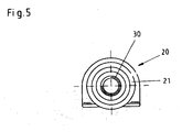
- the in the Fig. 2 to 5 Endpol 20 shown consists of an approximately cylindrical shaped body 21 made of a lead material.
- the upper end of the molded body 21 is denoted by 21a and the lower end by 21b.
- a Anformung 22 is provided, via which then the negative plates or the plus plates are connected.
- the upper end 21 a of the molded body 21 has a threaded sleeve 30 incorporated in the lead material of the end pole 20, which is provided with an internal thread 31 and consists of steel or another suitable material.
- the shaped body 21 of the end pole 20 accordingly Fig. 2 to 5 has stepwise widening shaped body sections.
- the end pole consists of a cylindrical shaped body which is provided, for example, in its upper portion with a groove structure formed on the outside wall side.
- the molding is provided with a plastic sheath 80.
- This end pole 120 also has, in its upper region, a threaded sleeve 30 made of steel or another suitable material, which is embedded in the lead material of the end pole.
- the threaded sleeve 30 with the internal thread 31 is homogeneously incorporated in the manufacture of the Endpols in the lead material of Endpols.
- the production of the Endpols 20 and 120 takes place in the cold press process.
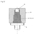
- the Fig. 10 . 11 . 12 . 13 show various process steps for the production of the end pole 20 of a lead material.
- This is based on a hollow mold 50 which may be formed in one or more parts.
- the hollow mold 50 is formed in two parts and consists of the two hollow mold parts 50a, 50b.
- a cavity 60 is formed, which corresponds to the shape of the end pole 20 to be produced. This cavity 60 is open at the bottom.
- the bottom-side opening is indicated at 61.
- a threaded sleeve 30 is arranged with an internal thread 31, wherein the length of the threaded sleeve 30 is sized according to the respective requirements.
- This threaded sleeve 30 made of steel extends with a portion 30a into the cavity 60, so that the threaded sleeve 30 protrudes with its upper portion 30b from the cavity 60.
- the amount of lead material 40 used is approximately that amount of lead material needed to make the end pole 20 and received by the cavity 60 of the mold 50.
- the lead material 40 is pressed into the cavity 60 of the mold 50 ( Fig. 11 ) until the entire cavity 60 is filled with the lead material ( Fig. 12 ), in which case at the same time the threaded sleeve 30 is homogeneously incorporated into the lead material of the molding, which forms the end pole 20.
- the pressing of the lead material in the cavity 60 of the cavity 50 is carried out by cold pressing, but this does not preclude that the lead material used can be preheated.
- the two hollow mold parts 50a, 50b are moved apart in the direction of the arrow X1 and the finished product, here the end pole 20, is obtained ( Fig. 13 and Fig. 2 ).
- Fig. 14 it is possible to carry out the method for producing Endpolen such that on the bottom-side opening 61 of the cavity 60 of the mold 50, the lead material, for. B. a Pb board 40, in a corresponding to the molded article quantity of material by means of a pressurized ram together with an internal thread 31 having seated on the Pb board 40 threaded sleeve 30 in the cold pressing process while homogenous involvement of the threaded sleeve in the Pb material of the molding 21 is pressed.
- the lead material for. B. a Pb board 40
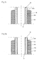
- Fig. 15 schematically shows the homogeneous integration of the material of the threaded sleeve 30 in the lead material 40 of the molding 21 which forms the Endpol 20.
- This homogeneous integration 90 in the outer wall region of the threaded sleeve 30 is indicated at 90.
- the outer wall surface 30c can be roughened or provided with a rough ground 35, which is designed, for example, as an outer wall profiling, so that in addition to the homogeneous incorporation a material toothing also takes place ( Fig. 16 .)
Landscapes
- Chemical & Material Sciences (AREA)
- Chemical Kinetics & Catalysis (AREA)
- Electrochemistry (AREA)
- General Chemical & Material Sciences (AREA)
- Connection Of Batteries Or Terminals (AREA)
Description
- Die Erfindung betrifft ein Verfahren zum Herstellen von Endpolen für den Anschluss elektrischer Polverbinder für Batterien, insbesondere leistungsstarke Akkumulatoren, stationäre Batterien und dgl., bei dem im Kaltpressverfahren Bleimaterial in einen Hohlraum einer Hohlform gepresst wird. Zudem betrifft die Erfindung einen Endpol für den Anschluss elektrischer Polverbinder für Batterien.
- Verfahren der eingangs genannten Art sind bekannt, wobei leistungsstarke Batterien und Akkumulatoren, stationäre Batterien im Prinzip den gleichen Aufbau aufweisen und in Straßenfahrzeugen und Flurförderzeugen eingesetzt werden. Neben Blei- und Säurebatterien sind Nickel-Batteriesysteme, Natrium-Batteriesysteme und Lithium-Batteriesysteme bekannt. Das Grundelement einer Kraftfahrzeugbatterie ist beispielsweise die Bleizelle, ein galvanisches Element, die sich aus einer größeren Anzahl positiver und negativer Platten zusammensetzt, die aus Blei und Bleiverbindungen bestehen. Statt einfacher Platten werden oftmals Gitterplatten mit einem Gitter aus hochwertigen Hartbleilegierungen eingesetzt, in das die aktive Masse eingepresst ist. Positive Platten und negative Platten unterscheiden sich dabei durch die Gitterform und die Art der aktiven Massen. Beide Plattensätze werden, um einen Plattenschluss zu vermeiden, durch Separatoren (Trennwände) aus säurefestem Material in einen bestimmten Abstand gehalten, um ein Kurzschließen durch Materialwandungen zu verhindern. Die gesamte Anordnung erfolgt in einem Blockkasten. Mit den positiven Platten und den negativen Platten verbundene Endpole dienen für den Anschluss elektrischer Polverbinder.
- Das Dokument
DE 41 38 760 A1 offenbart dabei ein Herstellungsverfahren für einen Formkörper, insbesondere für Batteriepole, bei dem der Formkörper einen Grundkörper aufweist, der mit einem Teilkörper drehfest verbunden ist, wobei der Grund- und der Teilkörper aus nicht-Eisen-Metall oder der eine Körper aus einem nicht-Eisen-Metall und der andere Körper aus Eisen bzw. Stahl besteht. Dabei werden der Grund- und der Teilkörper als Grund- und Teilkörperrohling in eine dem Formkörper entsprechende Pressform eingebracht. Zudem ist der Teilkörperrohling zumindest in einem Einschubbereich in eine dem Einschubbereich entsprechende Öffnung des Grundkörperrohlings eingebracht. Unter Druckaufwendung in der Pressform werden die beiden Rohlinge dann zu einem Grundkörper verpresst. Die beiden Rohlinge können dabei entweder im kalten oder im warmen Zustand verpresst werden. - Nachteilig bei dem vorbekannten Verfahren ist es, dass eine konstruktive Ausgestaltung der Öffnungen erfolgen muss.
- Es ist deshalb Aufgabe der vorliegenden Erfindung, ein Verfahren der eingangs genannten Art derart weiterzubilden, dass die genannten Nachteile des Verfahrens vermieden werden.
- Diese Aufgabe wird mit den Merkmalen des Anspruchs 1 oder 2 gelöst.
- Grundlegende Idee der Erfindung ist es, einen Teilkörperrohling, bspw. in Gestalt eines aufwendig gestalteten Endpols, während des Pressvorgangs in einen Grundkörperrohling aus Bleimaterial zu integrieren. Vielmehr ist gemäß der Erfindung vorgesehen, dass in dem oberen Bereich eines der Form des Endpols entsprechenden bodenseitig offenen Hohlraums einer ein- und mehrteiligen Hohlform eine mit einem Innengewinde versehene Hülse aus Stahl oder einem anderen geeigneten Material eingesetzt wird. Hierdurch kann im Falle eines Endpols auf einen aufwendig gestalteten Einschubbereich in dem Bleimaterial verzichtet werden.
- Alternativ zu diesem Verfahren kann dies auch dadurch erreicht werden, dass der Teilkörperrohling in Gestalt der Gewindehülse zusammen mit dem Bleimaterial in den Hohlraum gepresst wird. Auch bei dieser Verfahrensweise erfolgt eine homogene Einbindung der Gewindehülse in das Bleimaterial des Formkörpers bzw. des Endpols. Nach dieser Verfahrensvariante erfolgt keine Anordnung der Gewindehülse in den Hohlraum der Hohlform vor dem Einpressen des Bleimaterials in den Hohlraum.
- Beiden Verfahrensvarianten ist gemeinsam, dass ein Teilkörperrohling während des Pressvorgangs in einen Grundkörperrohling integriert wird.
- Weitere vorteilhafte Ausgestaltungen der Erfindung sind Gegenstand der Unteransprüche.
- So besteht z. B. die Möglichkeit, die Gewindehülse für den Anschluss elektrischer Polverbinder bei der Herstellung des Endpols in den Hohlraum der Hohlform anzuordnen, so dass dann durch das Kaltpressen des Blei-Materials die Gewindehülse in das Bleimaterial homogen eingebunden wird. Darüberhinaus besteht jedoch auch die Möglichkeit, die Gewindehülse zusammen mit dem Blei-Material in den Hohlraum der Hohlform zu pressen, so dass dann bei diesem Vorgang die Einbindung der Gewindehülse in das Material des Endpols erfolgt.
- Die Erfindung wird nachstehend anhand von Ausführungsbeispielen näher erläutert. Es zeigen:
- Fig. 1
- in einer schaubildlichen Ansicht eine Batterie mit aus dem Blockkasten der Batterie herausragenden Endpolen,
- Fig. 2
- eine schaubildliche Ansicht eines Endpols mit in das Endpol- Material homogen eingebundener Gewindehülse,
- Fig. 3
- eine Seitenansicht des Endpols gemäß
Fig. 2 , - Fig. 4
- eine Ansicht von unten auf den Endpol gemäß
Fig. 2 , - Fig. 5
- eine Ansicht von oben auf den Endpol gemäß
Fig. 2 , - Fig. 6
- eine schaubildliche Ansicht einer weiteren Ausführungsform eines Endpols mit in das Endpol-Material homogen eingebundener Gewindehülse und mit einer Kunststoffummantelung,
- Fig. 7
- eine Seitenansicht des Endpols gemäß
Fig. 6 , - Fig. 8
- eine Ansicht von unten auf den Endpol gemäß
Fig. 6 , - Fig. 9
- eine Ansicht von oben auf den Endpol gemäß
Fig. 6 , - Fig. 10
- einen senkrechten Schnitt durch eine Hohlform mit einem der Form des zu erstellenden Endpols entsprechenden Hohl- raum mit im oberen Bereich eingesetzter Gewindehülse, ei- nem Pressstempel und einer Pb-Platine vor dem Einpressen des Blei-Materials in den Hohlraum der Hohlform,
- Fig. 11
- einen senkrechten Schnitt durch die Hohlform gemäß
Fig. 10 , jedoch mit in den Hohlraum der Hohlform teilweise ein- gepresstem Blei-Material, - Fig. 12
- einen senkrechten Schnitt durch die Hohlform gemäß
Fig. 10 mit in den Hohlraum eingepresstem Blei-Material bei gleich- zeitiger homogener Einbindung der Gewindehülse in das Blei-Material, - Fig. 13
- einen senkrechten Schnitt durch die Hohlform gemäß
Fig. 10 mit fertig hergestelltem Endpol vor dem Öffnen der Hohlform, - Fig. 14
- einen senkrechten Schnitt durch eine Hohlform mit einem der Form des zu erstellenden Endpols entsprechenden Hohl- raum mit auf die Pb-Platine aufgesetzter Gewindehülse vor dem Einpressen des Blei-Materials zusammen mit der Ge- windehülse in dem Hohlraum der Hohlform,
- Fig. 15
- einen senkrechten Schnitt der in das Blei-Material des End- pols homogen eingebundenen Gewindehülse und
- Fig. 16
- einen senkrechten Schnitt durch die Gewindehülse mit einer Außenwandaufrauhung bei erfolgter homogenen Einbindung der Gewindehülse in das Blei-Material des Endpols.
-
Fig. 1 zeigt eine herkömmliche Batterie 10, die aus einem Blockkasten 11 besteht, der mit einem oberen Blockdeckel 13 versehen ist. Der Innenraum, d. h. die Zelle des Blockkastens, ist unterteilt durch Zelltrennwände 12 zur Aufnahme von Plus-Platten 14 und Negativ-Platten 15, wobei die Plus-Platten und die Negativ-Platten über Polbrücken miteinander verbunden sind, die mit Endpolen 20, 20' verbunden sind. - Der in den
Fig. 2 bis 5 dargestellte Endpol 20 besteht aus einem in etwa zylindrischen Formkörper 21 aus einem Blei-Material. Das obere Ende des Formkörpers 21 ist mit 21a und das untere Ende mit 21b bezeichnet. An das untere Ende 21b des Formkörpers 21 ist eine Anformung 22 vorgesehen, über die dann die Negativ-Platten oder die Plus-Platten angeschlossen werden. Das obere Ende 21a des Formkörpers 21 weist eine in das Blei-Material des Endpols 20 eingearbeitete Gewindehülse 30 auf, die mit einem Innengewinde 31 versehen ist und aus Stahl oder einem anderen geeigneten Werkstoff besteht. Der Formkörper 21 des Endpols 20 entsprechendFig. 2 bis 5 weist stufenweise sich verbreiternde Formkörperabschnitte auf. - Bei der Ausführungsform eines Endpols 120 entsprechend der
Fig. 6 bis 9 besteht der Endpol aus einem zylindrischen Formkörper der beispielsweise in seinem oberen Abschnitt mit einer außenwandseitig ausgebildeten Rillenstruktur versehen ist. Außerdem ist der Formkörper mit einem Kunststoffmantel 80 versehen. Auch dieser Endpol 120 weist in seinem oberen Bereich eine in das Blei-Material des Endpols eingelassene Gewindehülse 30 aus Stahl oder einem anderen geeigneten Werkstoff auf. - Die Gewindehülse 30 mit dem Innengewinde 31 ist bei der Herstellung des Endpols in das Blei-Material des Endpols homogen eingebunden. Die Herstellung des Endpols 20 bzw. 120 erfolgt dabei im Kaltpressverfahren.
- Die
Fig. 10 ,11 ,12 ,13 zeigen verschiedene Verfahrensschritte für die Herstellung des Endpols 20 aus einem Blei-Material. Hierbei wird ausgegangen von einer Hohlform 50 die einteilig oder mehrteilig ausgebildet sein kann. Im dargestellten Ausführungsbeispiel ist die Hohlform 50 zweiteilig ausgebildet und besteht aus den beiden Hohlformteilen 50a, 50b. In der Hohlform 50 ist ein Hohlraum 60 ausgebildet, der der Form des herzustellenden Endpols 20 entspricht. Dieser Hohlraum 60 ist bodenseitig offen ausgebildet. Die bodenseitige Öffnung ist bei 61 angedeutet. - In dem oberen Bereich des Hohlraumes 60 der Hohlform 50 ist eine Gewindehülse 30 mit einem Innengewinde 31 angeordnet, wobei die Länge der Gewindehülse 30 den jeweiligen Erfordernissen entsprechend bemessen ist. Diese Gewindehülse 30 aus Stahl erstreckt sich dabei mit einem Abschnitt 30a in den Hohlraum 60, so dass die Gewindehülse 30 mit ihrem oberen Abschnitt 30b aus dem Hohlraum 60 herausragt.
- Das Einpressen des Blei-Materials 40 in den Hohlraum 60 der Hohlform 50 erfolgt mittels eines druckbeaufschlagten Pressstempels 70. Vermittels dieses Pressstempels 70 wird das Blei-Material z. B. in Form einer Pb-Platine 40 in den Hohlraum 60 der Hohlform 50 gepresst, wobei der Pressstempel 70 in Pfeilrichtung X gegen die Hohlform 50 bewegt wird (
Fig. 10 ). - Die Menge des eingesetzten Blei-Materials 40 entspricht in etwa derjenigen Menge an Blei-Material, die für die Herstellung des Endpols 20 benötigt wird und von dem Hohlraum 60 der Hohlform 50 aufgenommen wird.
- Bei einem Vorschub des Pressstempels 70 in Pfeilrichtung X wird das Blei-Material 40 in den Hohlraum 60 der Hohlform 50 gepresst (
Fig. 11 ) bis der gesamte Hohlraum 60 mit dem Blei-Material ausgefüllt ist (Fig. 12 ), wobei dann gleichzeitig die Gewindehülse 30 homogen eingebunden wird in das Blei-Material des Formkörpers, der den Endpol 20 bildet. Das Einpressen des Blei-Materials in den Hohlraum 60 des Hohlraumes 50 erfolgt im Kaltpressverfahren, was jedoch nicht ausschließt, dass das eingesetzte Blei-Material vorgewärmt sein kann. - Ist der Herstellungsprozess beendet, dann werden die beiden Hohlformteile 50a, 50b in Pfeilrichtung X1 auseinander bewegt und das Fertigprodukt, hier der Endpol 20, erhalten (
Fig. 13 undFig. 2 ). - Gemäß
Fig. 14 besteht die Möglichkeit, das Verfahren zum Herstellen von Endpolen derart vorzunehmen, dass über die bodenseitige Öffnung 61 des Hohlraumes 60 der Hohlform 50 das Blei-Material, z. B. eine Pb-Platine 40, in einer dem herzustellenden Formkörper entsprechenden Materialmenge vermittels eines druckbeaufschlagten Pressstempels zusammen mit einer ein Innengewinde 31 aufweisenden auf der Pb-Platine 40 aufsitzenden Gewindehülse 30 im Kaltpressverfahren bei gleichzeitiger homogener Einbindung der Gewindehülse in das Pb-Material des Formkörpers 21 gepresst wird. Nach diesem Verfahren erfolgt somit keine Anordnung der Gewindehülse 30 in den Hohlraum 60 der Hohlform 50 vor dem Einpressen des Blei-Materials in den Hohlraum 60, sondern die Gewindehülse 30 wird zusammen mit dem Blei-Material in den Hohlraum 60 gepresst. Auch bei dieser Verfahrensweise erfolgt eine homogene Einbindung der Gewindehülse 30 in das Blei-Material des Formkörpers 21 bzw. des Endpols 20 (Fig. 14 ). -
Fig. 15 zeigt schematisch die homogene Einbindung des Materials der Gewindehülse 30 in das Blei-Material 40 des Formkörpers 21 der den Endpol 20 bildet. Diese homogene Einbindung 90 im Außenwandbereich der Gewindehülse 30 ist bei 90 angedeutet. - Um diese homogene Einbindung 90 noch zu verstärken, kann nach einer weiteren Ausführungsform die Außenwandfläche 30c aufgerauht bzw. mit einem Rauhgrund 35 versehen sein, der beispielsweise als Außenwandprofilierung ausgebildet ist, so dass neben der homogenen Einbindung auch noch zusätzlich eine Materialverzahnung erfolgt (
Fig. 16 .)
Claims (4)
- Verfahren zum Herstellen von Endpolen (20; 120) für den Anschluss elektrischer Polverbinder für Batterien, insbesondere leistungsstarke Akkumulatoren, stationäre Batterien u. dgl., bei dem im Kaltpressverfahren Bleimaterial in einen Hohlraum einer Hohlform gepresst wird,
dadurch gekennzeichnet,
dass in dem oberen Bereich eines der Form des Endpols (20; 120) entsprechenden, bodenseitig offenen Hohlraumes (60) einer ein- oder mehrteiligen Hohlform (50) eine mit einem Innengewinde (31) und mit einem nach auβen zeigenden offenen sowie mit einem in einen Formkörper (21) einzubindenden, abgeschlossenen Ende versehene sowie mit ihrem oberen Abschnitt aus dem Hohlraum (60) herausragende Hülse (30) aus Stahl oder einem anderen geeignetem Material passgenau eingesetzt, hierauf vermittels eines druckbeaufschlagten Pressstempels (70) das Material einer Pb-Platine (40) in einer dem herzustellenden Formkörper (21) entsprechenden Materialmenge in den Hohlraum (60) der Hohlform (50)im Kaltpressverfahren bei gleichzeitiger homogener Einbindung der Gewindehülse (30) in das Blei-Material des Formkörpers (21) gepresst und danach der Formkörper (21) mit seiner homogen in das Blei-Material eingebundenen Gewindehülse (30) der Hohlform (50) entnommen wird. - Verfahren zum Herstellen von Endpolen (20; 120) für den Anschluss elektrischer Polverbinder für Batterien, insbesondere für leistungsstarke Akkumulatoren, stationäre Batterien u. dgl., bei dem im Kaltpressverfahren Bleimaterial in einen Hohlraum einer Hohlform gepresst wird,
dadurch gekennzeichnet,
dass über die bodenseitige Öffnung (61) eines der Form des herzustellenden Endpols (20; 120) entsprechenden Hohlraumes (60) einer ein- oder mehrteiligen Hohlform (50) das Material einer Pb-Platine (40) in einer dem herzustellenden Formkörper (21) entsprechenden Materialmenge vermittels eines druckbeaufschlagten Pressstempels (70) zusammen mit einer ein Innengewinde (31) aufweisenden, auf der Pb-Platine (40) aufsitzenden Gewindehülse (30) im Kaltpressverfahren bei gleichzeitiger homogener Einbindung der Gewindehülse (30) in das Pb-Material des Formkörpers (21) in den Hohlraum (60) der Hohlform (50) gepresst und danach der Formkörper (21) mit seiner homogenen in das Pb-Material eingebundenen Gewindehülse (30) der Hohlform (50) entnommen wird. - Verfahren nach einem der Ansprüche 1 oder 2,
dadurch gekennzeichnet,
dass der Formkörper (21) des Endpols (20; 120) mit seiner homogen eingebundenen Gewindehülse (30) mit einem Kunststoff ummantelt wird. - Verfahren nach einem der Ansprüche 1 bis 3,
dadurch gekennzeichnet,
dass die Außenwandfläche (30c) der Gewindehülse (30) aufgerauht ist bzw. mit einem Rauhgrund in Form einer Außenwandprofilierung versehen ist.
Priority Applications (5)
| Application Number | Priority Date | Filing Date | Title |
|---|---|---|---|
| AT10172370T ATE549759T1 (de) | 2002-04-24 | 2002-04-24 | Endpol für den anschluss elektrischer polverbinder für batterien |
| AT02009201T ATE504094T1 (de) | 2002-04-24 | 2002-04-24 | Verfahren zur herstellung von endpolen für den anschluss elektrischer polverbinder für batterien |
| EP02009201A EP1367660B1 (de) | 2002-04-24 | 2002-04-24 | Verfahren zur Herstellung von Endpolen für den Anschluss elektrischer Polverbinder für Batterien |
| EP10172370A EP2244320B1 (de) | 2002-04-24 | 2002-04-24 | Endpol für den Anschluss elektrischer Polverbinder für Batterien |
| DE50214988T DE50214988D1 (de) | 2002-04-24 | 2002-04-24 | Verfahren zur Herstellung von Endpolen für den Anschluss elektrischer Polverbinder für Batterien |
Applications Claiming Priority (1)
| Application Number | Priority Date | Filing Date | Title |
|---|---|---|---|
| EP02009201A EP1367660B1 (de) | 2002-04-24 | 2002-04-24 | Verfahren zur Herstellung von Endpolen für den Anschluss elektrischer Polverbinder für Batterien |
Related Child Applications (1)
| Application Number | Title | Priority Date | Filing Date |
|---|---|---|---|
| EP10172370.8 Division-Into | 2010-08-10 |
Publications (2)
| Publication Number | Publication Date |
|---|---|
| EP1367660A1 EP1367660A1 (de) | 2003-12-03 |
| EP1367660B1 true EP1367660B1 (de) | 2011-03-30 |
Family
ID=29414667
Family Applications (2)
| Application Number | Title | Priority Date | Filing Date |
|---|---|---|---|
| EP10172370A Expired - Lifetime EP2244320B1 (de) | 2002-04-24 | 2002-04-24 | Endpol für den Anschluss elektrischer Polverbinder für Batterien |
| EP02009201A Expired - Lifetime EP1367660B1 (de) | 2002-04-24 | 2002-04-24 | Verfahren zur Herstellung von Endpolen für den Anschluss elektrischer Polverbinder für Batterien |
Family Applications Before (1)
| Application Number | Title | Priority Date | Filing Date |
|---|---|---|---|
| EP10172370A Expired - Lifetime EP2244320B1 (de) | 2002-04-24 | 2002-04-24 | Endpol für den Anschluss elektrischer Polverbinder für Batterien |
Country Status (3)
| Country | Link |
|---|---|
| EP (2) | EP2244320B1 (de) |
| AT (2) | ATE549759T1 (de) |
| DE (1) | DE50214988D1 (de) |
Families Citing this family (1)
| Publication number | Priority date | Publication date | Assignee | Title |
|---|---|---|---|---|
| DE102007045435A1 (de) * | 2007-09-22 | 2009-04-02 | Jungheinrich Aktiengesellschaft | Batteriebetriebenes Flurförderzeug |
Family Cites Families (6)
| Publication number | Priority date | Publication date | Assignee | Title |
|---|---|---|---|---|
| US1484481A (en) * | 1921-07-01 | 1924-02-19 | Milo H Dunbar | Battery connection |
| US3256511A (en) * | 1964-03-13 | 1966-06-14 | Herrmann Willi | Terminal connector for batteries |
| DE2757568C2 (de) * | 1977-12-23 | 1986-05-15 | Varta Batterie Ag, 3000 Hannover | Elektrischer Akkumulator |
| IT1214528B (it) * | 1986-09-23 | 1990-01-18 | Aquila Piombo Per Caccia E Tir | Procedimento per la realizzazione di un polo o terminale di batteria elettrica, apparecchiatura per attuare tale procedimento, nonche'polo o terminale di batteria elettrica cosi' ottenuto. |
| DE4138760A1 (de) * | 1991-11-26 | 1993-05-27 | Imb Innovativer Maschinenbau G | Herstellungsverfahren fuer einen formkoerper, insbesondere fuer batteriepole |
| DE19936797C1 (de) * | 1999-08-04 | 2000-10-26 | Welcker F | Polanschlussverschraubung für Bleiakkumulatoren |
-
2002
- 2002-04-24 EP EP10172370A patent/EP2244320B1/de not_active Expired - Lifetime
- 2002-04-24 DE DE50214988T patent/DE50214988D1/de not_active Expired - Lifetime
- 2002-04-24 AT AT10172370T patent/ATE549759T1/de active
- 2002-04-24 AT AT02009201T patent/ATE504094T1/de active
- 2002-04-24 EP EP02009201A patent/EP1367660B1/de not_active Expired - Lifetime
Also Published As
| Publication number | Publication date |
|---|---|
| ATE504094T1 (de) | 2011-04-15 |
| EP2244320B1 (de) | 2012-03-14 |
| EP1367660A1 (de) | 2003-12-03 |
| EP2244320A1 (de) | 2010-10-27 |
| ATE549759T1 (de) | 2012-03-15 |
| DE50214988D1 (de) | 2011-05-12 |
Similar Documents
| Publication | Publication Date | Title |
|---|---|---|
| CH620050A5 (de) | ||
| DE2044713A1 (de) | Verfahren zur Herstellung eines aus Kunstharz bestehenden Behalters bzw Kastens und nach diesem Verfahren hergestelltes Erzeugnis | |
| EP0590644A1 (de) | Verfahrem zum Umspritzen von elektrischen Kontaktbahnen | |
| DE102013209775B3 (de) | Speisereinsatz | |
| EP0241009B1 (de) | Verfahren und Formwerkzeug zur Herstellung eines in ein Mauerwerk einsetzbaren Steigbügels | |
| DE2443422A1 (de) | Elektrischer akkumulator | |
| DE4013509C2 (de) | Verfahren zur Herstellung von Steckern mit einem Kunststoff-Gehäuse und eingebetteten Kontaktzungen | |
| EP2342775B1 (de) | Gewalzte elektrode für einen akkumulator | |
| EP2288480B1 (de) | Form zur herstellung von betonformsteinen | |
| DE2407426C3 (de) | Verfahren und Vorrichtung zur Herstellung von Kontaktfahnen mit Leitbahnen auf einer Elektrodenplatte | |
| DE2645342A1 (de) | Verfahren und vorrichtung zum giessen von plattenverbindungsstuecken und/oder zellenverbindungsanordnungen von elektrischen akkumulatorbatterien | |
| EP1367660B1 (de) | Verfahren zur Herstellung von Endpolen für den Anschluss elektrischer Polverbinder für Batterien | |
| DE102017204882A1 (de) | Verfahren zur Herstellung einer Airbagabdeckung und Formwerkzeug | |
| DE19922046C2 (de) | Verfahren zum Formen einer Kurbelwelle und Verfahren zum Herstellen einer Kurbelwelle | |
| EP4238168A1 (de) | Batterieschale aufweisend ein verstärkungsvlies, herstellverfahren und traktionsbatterie | |
| DE102008000458A1 (de) | Form zur Herstellung von Betonformsteinen und Verfahren zur Herstellung einer Formkernanordnung einer solchen Form | |
| DE102017131280A1 (de) | Verfahren zum Herstellen eines Formteils sowie Speisereinsatz zur Verwendung in einem solchen Verfahren | |
| WO2017162331A1 (de) | Kunststoff-bauteil mit zumindest einer elektrischen leiterbahn und verfahren zu seiner herstellung | |
| EP3008766B1 (de) | Akkumulator und verfahren zur herstellung eines akkumulators | |
| DE2823871C2 (de) | Verfahren zur Herstellung eines Verbundkörpers, insbesondere einer Akkumulator-Gitterplatte | |
| DE2925294B2 (de) | Akkumulator | |
| DE102023203712B3 (de) | Vorrichtung zum Herstellen eines Innenverkleidungsteils | |
| DE856910C (de) | Verbindung benachbarter Pole von elektrischen Sammelbatterien mit einem durch Zwischenwaende unterteilten Gehaeuse und Verfahren zu ihrer Herstellung | |
| EP0347405A2 (de) | Band- oder riemenförmiger Bauteil, insbesondere Uhrband | |
| DE2858186C2 (de) | Verfahren zur Herstellung eines Verbundkörpers, insbesondere einer Akkumulator-Gitterplatte |
Legal Events
| Date | Code | Title | Description |
|---|---|---|---|
| PUAI | Public reference made under article 153(3) epc to a published international application that has entered the european phase |
Free format text: ORIGINAL CODE: 0009012 |
|
| 17P | Request for examination filed |
Effective date: 20021130 |
|
| AK | Designated contracting states |
Kind code of ref document: A1 Designated state(s): AT BE CH CY DE DK ES FI FR GB GR IE IT LI LU MC NL PT SE TR |
|
| AX | Request for extension of the european patent |
Extension state: AL LT LV MK RO SI |
|
| AKX | Designation fees paid |
Designated state(s): AT BE CH CY DE DK ES FI FR GB GR IE IT LI LU MC NL PT SE TR |
|
| 17Q | First examination report despatched |
Effective date: 20060622 |
|
| RAP1 | Party data changed (applicant data changed or rights of an application transferred) |
Owner name: JL GOSLAR GMBH & CO. KG |
|
| GRAP | Despatch of communication of intention to grant a patent |
Free format text: ORIGINAL CODE: EPIDOSNIGR1 |
|
| RIC1 | Information provided on ipc code assigned before grant |
Ipc: H01M 2/30 20060101AFI20100909BHEP Ipc: H01M 10/12 20060101ALN20100909BHEP |
|
| RTI1 | Title (correction) |
Free format text: METHOD FOR FABRICATING TERMINAL PINS FOR THE CONNECTION OF ELECTRICAL TERMINAL CONNECTOR FOR BATTERIES |
|
| GRAS | Grant fee paid |
Free format text: ORIGINAL CODE: EPIDOSNIGR3 |
|
| GRAA | (expected) grant |
Free format text: ORIGINAL CODE: 0009210 |
|
| AK | Designated contracting states |
Kind code of ref document: B1 Designated state(s): AT BE CH CY DE DK ES FI FR GB GR IE IT LI LU MC NL PT SE TR |
|
| REG | Reference to a national code |
Ref country code: GB Ref legal event code: FG4D Free format text: NOT ENGLISH |
|
| REG | Reference to a national code |
Ref country code: CH Ref legal event code: EP |
|
| REG | Reference to a national code |
Ref country code: IE Ref legal event code: FG4D |
|
| REF | Corresponds to: |
Ref document number: 50214988 Country of ref document: DE Date of ref document: 20110512 Kind code of ref document: P |
|
| REG | Reference to a national code |
Ref country code: DE Ref legal event code: R096 Ref document number: 50214988 Country of ref document: DE Effective date: 20110512 |
|
| REG | Reference to a national code |
Ref country code: NL Ref legal event code: T3 |
|
| PG25 | Lapsed in a contracting state [announced via postgrant information from national office to epo] |
Ref country code: SE Free format text: LAPSE BECAUSE OF FAILURE TO SUBMIT A TRANSLATION OF THE DESCRIPTION OR TO PAY THE FEE WITHIN THE PRESCRIBED TIME-LIMIT Effective date: 20110330 Ref country code: GR Free format text: LAPSE BECAUSE OF FAILURE TO SUBMIT A TRANSLATION OF THE DESCRIPTION OR TO PAY THE FEE WITHIN THE PRESCRIBED TIME-LIMIT Effective date: 20110701 |
|
| PG25 | Lapsed in a contracting state [announced via postgrant information from national office to epo] |
Ref country code: CY Free format text: LAPSE BECAUSE OF FAILURE TO SUBMIT A TRANSLATION OF THE DESCRIPTION OR TO PAY THE FEE WITHIN THE PRESCRIBED TIME-LIMIT Effective date: 20110330 Ref country code: FI Free format text: LAPSE BECAUSE OF FAILURE TO SUBMIT A TRANSLATION OF THE DESCRIPTION OR TO PAY THE FEE WITHIN THE PRESCRIBED TIME-LIMIT Effective date: 20110330 |
|
| REG | Reference to a national code |
Ref country code: IE Ref legal event code: FD4D |
|
| BERE | Be: lapsed |
Owner name: JL GOSLAR G.M.B.H. & CO. KG Effective date: 20110430 |
|
| PG25 | Lapsed in a contracting state [announced via postgrant information from national office to epo] |
Ref country code: PT Free format text: LAPSE BECAUSE OF FAILURE TO SUBMIT A TRANSLATION OF THE DESCRIPTION OR TO PAY THE FEE WITHIN THE PRESCRIBED TIME-LIMIT Effective date: 20110801 |
|
| PG25 | Lapsed in a contracting state [announced via postgrant information from national office to epo] |
Ref country code: MC Free format text: LAPSE BECAUSE OF NON-PAYMENT OF DUE FEES Effective date: 20110430 Ref country code: ES Free format text: LAPSE BECAUSE OF FAILURE TO SUBMIT A TRANSLATION OF THE DESCRIPTION OR TO PAY THE FEE WITHIN THE PRESCRIBED TIME-LIMIT Effective date: 20110711 |
|
| REG | Reference to a national code |
Ref country code: CH Ref legal event code: PL |
|
| PG25 | Lapsed in a contracting state [announced via postgrant information from national office to epo] |
Ref country code: IE Free format text: LAPSE BECAUSE OF FAILURE TO SUBMIT A TRANSLATION OF THE DESCRIPTION OR TO PAY THE FEE WITHIN THE PRESCRIBED TIME-LIMIT Effective date: 20110330 Ref country code: CH Free format text: LAPSE BECAUSE OF NON-PAYMENT OF DUE FEES Effective date: 20110430 Ref country code: BE Free format text: LAPSE BECAUSE OF NON-PAYMENT OF DUE FEES Effective date: 20110430 Ref country code: LI Free format text: LAPSE BECAUSE OF NON-PAYMENT OF DUE FEES Effective date: 20110430 |
|
| PLBE | No opposition filed within time limit |
Free format text: ORIGINAL CODE: 0009261 |
|
| STAA | Information on the status of an ep patent application or granted ep patent |
Free format text: STATUS: NO OPPOSITION FILED WITHIN TIME LIMIT |
|
| PG25 | Lapsed in a contracting state [announced via postgrant information from national office to epo] |
Ref country code: DK Free format text: LAPSE BECAUSE OF FAILURE TO SUBMIT A TRANSLATION OF THE DESCRIPTION OR TO PAY THE FEE WITHIN THE PRESCRIBED TIME-LIMIT Effective date: 20110330 |
|
| 26N | No opposition filed |
Effective date: 20120102 |
|
| REG | Reference to a national code |
Ref country code: DE Ref legal event code: R097 Ref document number: 50214988 Country of ref document: DE Effective date: 20120102 |
|
| REG | Reference to a national code |
Ref country code: AT Ref legal event code: MM01 Ref document number: 504094 Country of ref document: AT Kind code of ref document: T Effective date: 20110424 |
|
| PG25 | Lapsed in a contracting state [announced via postgrant information from national office to epo] |
Ref country code: AT Free format text: LAPSE BECAUSE OF NON-PAYMENT OF DUE FEES Effective date: 20110424 |
|
| REG | Reference to a national code |
Ref country code: DE Ref legal event code: R082 Ref document number: 50214988 Country of ref document: DE Representative=s name: EINSEL & KOLLEGEN PATENTANWAELTE, DE |
|
| REG | Reference to a national code |
Ref country code: DE Ref legal event code: R082 Ref document number: 50214988 Country of ref document: DE Representative=s name: EINSEL & KOLLEGEN PATENTANWAELTE, DE Effective date: 20130313 Ref country code: DE Ref legal event code: R081 Ref document number: 50214988 Country of ref document: DE Owner name: JL GOSLAR GMBH, DE Free format text: FORMER OWNER: JL GOSLAR GMBH & CO. KG, 38640 GOSLAR, DE Effective date: 20130313 Ref country code: DE Ref legal event code: R081 Ref document number: 50214988 Country of ref document: DE Owner name: JL GOSLAR GMBH, DE Free format text: FORMER OWNER: JL GOSLAR GMBH, 22525 HAMBURG, DE Effective date: 20110303 Ref country code: DE Ref legal event code: R082 Ref document number: 50214988 Country of ref document: DE Representative=s name: PATENTANWAELTE EINSEL & KOLLEGEN, DE Effective date: 20130313 |
|
| PG25 | Lapsed in a contracting state [announced via postgrant information from national office to epo] |
Ref country code: LU Free format text: LAPSE BECAUSE OF NON-PAYMENT OF DUE FEES Effective date: 20110424 |
|
| REG | Reference to a national code |
Ref country code: NL Ref legal event code: TD Effective date: 20130723 Ref country code: NL Ref legal event code: SD Effective date: 20130723 |
|
| REG | Reference to a national code |
Ref country code: GB Ref legal event code: 732E Free format text: REGISTERED BETWEEN 20130801 AND 20130807 |
|
| PG25 | Lapsed in a contracting state [announced via postgrant information from national office to epo] |
Ref country code: TR Free format text: LAPSE BECAUSE OF FAILURE TO SUBMIT A TRANSLATION OF THE DESCRIPTION OR TO PAY THE FEE WITHIN THE PRESCRIBED TIME-LIMIT Effective date: 20110330 |
|
| REG | Reference to a national code |
Ref country code: FR Ref legal event code: CD Owner name: JM GOSLAR GMBH, DE Effective date: 20131008 Ref country code: FR Ref legal event code: CA Effective date: 20131008 Ref country code: FR Ref legal event code: TP Owner name: JM GOSLAR GMBH, DE Effective date: 20131008 |
|
| PGFP | Annual fee paid to national office [announced via postgrant information from national office to epo] |
Ref country code: GB Payment date: 20140402 Year of fee payment: 13 |
|
| PGFP | Annual fee paid to national office [announced via postgrant information from national office to epo] |
Ref country code: NL Payment date: 20140415 Year of fee payment: 13 Ref country code: IT Payment date: 20140424 Year of fee payment: 13 Ref country code: FR Payment date: 20140430 Year of fee payment: 13 Ref country code: DE Payment date: 20140415 Year of fee payment: 13 |
|
| REG | Reference to a national code |
Ref country code: DE Ref legal event code: R119 Ref document number: 50214988 Country of ref document: DE |
|
| GBPC | Gb: european patent ceased through non-payment of renewal fee |
Effective date: 20150424 |
|
| REG | Reference to a national code |
Ref country code: NL Ref legal event code: MM Effective date: 20150501 |
|
| PG25 | Lapsed in a contracting state [announced via postgrant information from national office to epo] |
Ref country code: GB Free format text: LAPSE BECAUSE OF NON-PAYMENT OF DUE FEES Effective date: 20150424 Ref country code: IT Free format text: LAPSE BECAUSE OF NON-PAYMENT OF DUE FEES Effective date: 20150424 Ref country code: DE Free format text: LAPSE BECAUSE OF NON-PAYMENT OF DUE FEES Effective date: 20151103 |
|
| REG | Reference to a national code |
Ref country code: FR Ref legal event code: ST Effective date: 20151231 |
|
| PG25 | Lapsed in a contracting state [announced via postgrant information from national office to epo] |
Ref country code: FR Free format text: LAPSE BECAUSE OF NON-PAYMENT OF DUE FEES Effective date: 20150430 |
|
| PG25 | Lapsed in a contracting state [announced via postgrant information from national office to epo] |
Ref country code: NL Free format text: LAPSE BECAUSE OF NON-PAYMENT OF DUE FEES Effective date: 20150501 |