EP1367390A1 - Verfahren und Vorrichtung zur Bestimmung der Schallgeschwindigkeit in einem Werkstoff in Abhängigkeit der Temperatur - Google Patents
Verfahren und Vorrichtung zur Bestimmung der Schallgeschwindigkeit in einem Werkstoff in Abhängigkeit der Temperatur Download PDFInfo
- Publication number
- EP1367390A1 EP1367390A1 EP03010646A EP03010646A EP1367390A1 EP 1367390 A1 EP1367390 A1 EP 1367390A1 EP 03010646 A EP03010646 A EP 03010646A EP 03010646 A EP03010646 A EP 03010646A EP 1367390 A1 EP1367390 A1 EP 1367390A1
- Authority
- EP
- European Patent Office
- Prior art keywords
- sample body
- sound
- speed
- temperature
- sample
- Prior art date
- Legal status (The legal status is an assumption and is not a legal conclusion. Google has not performed a legal analysis and makes no representation as to the accuracy of the status listed.)
- Granted
Links
- 239000000463 material Substances 0.000 title claims abstract description 23
- 238000000034 method Methods 0.000 title claims description 33
- 238000002604 ultrasonography Methods 0.000 claims abstract description 14
- 239000000523 sample Substances 0.000 claims description 59
- 238000005259 measurement Methods 0.000 claims description 12
- XLYOFNOQVPJJNP-UHFFFAOYSA-N water Substances O XLYOFNOQVPJJNP-UHFFFAOYSA-N 0.000 claims description 6
- 238000010438 heat treatment Methods 0.000 claims description 5
- 229910000831 Steel Inorganic materials 0.000 claims description 4
- 239000010959 steel Substances 0.000 claims description 4
- 230000008859 change Effects 0.000 claims description 3
- 238000001816 cooling Methods 0.000 claims description 3
- 230000008878 coupling Effects 0.000 claims description 3
- 238000010168 coupling process Methods 0.000 claims description 3
- 238000005859 coupling reaction Methods 0.000 claims description 3
- 239000002184 metal Substances 0.000 claims description 2
- 229910052751 metal Inorganic materials 0.000 claims description 2
- 238000005096 rolling process Methods 0.000 description 7
- 238000011156 evaluation Methods 0.000 description 5
- 230000005284 excitation Effects 0.000 description 4
- 230000003287 optical effect Effects 0.000 description 3
- 241000271559 Dromaiidae Species 0.000 description 2
- 230000009286 beneficial effect Effects 0.000 description 2
- 238000001514 detection method Methods 0.000 description 2
- 238000005516 engineering process Methods 0.000 description 2
- 238000001704 evaporation Methods 0.000 description 2
- 230000008020 evaporation Effects 0.000 description 2
- 238000004519 manufacturing process Methods 0.000 description 2
- 230000008569 process Effects 0.000 description 2
- 230000009467 reduction Effects 0.000 description 2
- 239000007858 starting material Substances 0.000 description 2
- 244000089486 Phragmites australis subsp australis Species 0.000 description 1
- 238000002679 ablation Methods 0.000 description 1
- 230000003321 amplification Effects 0.000 description 1
- 230000006835 compression Effects 0.000 description 1
- 238000007906 compression Methods 0.000 description 1
- 238000010276 construction Methods 0.000 description 1
- 239000002826 coolant Substances 0.000 description 1
- 230000003247 decreasing effect Effects 0.000 description 1
- 230000001419 dependent effect Effects 0.000 description 1
- 238000013461 design Methods 0.000 description 1
- 238000011161 development Methods 0.000 description 1
- 238000002592 echocardiography Methods 0.000 description 1
- 230000000694 effects Effects 0.000 description 1
- 238000001914 filtration Methods 0.000 description 1
- 238000011835 investigation Methods 0.000 description 1
- 229910001338 liquidmetal Inorganic materials 0.000 description 1
- 238000012544 monitoring process Methods 0.000 description 1
- 238000003199 nucleic acid amplification method Methods 0.000 description 1
- 239000013307 optical fiber Substances 0.000 description 1
- 230000002093 peripheral effect Effects 0.000 description 1
- 238000006722 reduction reaction Methods 0.000 description 1
- 238000012216 screening Methods 0.000 description 1
- 238000004513 sizing Methods 0.000 description 1
- 230000005236 sound signal Effects 0.000 description 1
- 239000002344 surface layer Substances 0.000 description 1
- 238000012360 testing method Methods 0.000 description 1
- 230000009466 transformation Effects 0.000 description 1
- 238000000844 transformation Methods 0.000 description 1
- 238000009683 ultrasonic thickness measurement Methods 0.000 description 1
Images


Classifications
-
- G—PHYSICS
- G01—MEASURING; TESTING
- G01H—MEASUREMENT OF MECHANICAL VIBRATIONS OR ULTRASONIC, SONIC OR INFRASONIC WAVES
- G01H5/00—Measuring propagation velocity of ultrasonic, sonic or infrasonic waves, e.g. of pressure waves
-
- G—PHYSICS
- G01—MEASURING; TESTING
- G01N—INVESTIGATING OR ANALYSING MATERIALS BY DETERMINING THEIR CHEMICAL OR PHYSICAL PROPERTIES
- G01N29/00—Investigating or analysing materials by the use of ultrasonic, sonic or infrasonic waves; Visualisation of the interior of objects by transmitting ultrasonic or sonic waves through the object
- G01N29/04—Analysing solids
- G01N29/07—Analysing solids by measuring propagation velocity or propagation time of acoustic waves
-
- G—PHYSICS
- G01—MEASURING; TESTING
- G01N—INVESTIGATING OR ANALYSING MATERIALS BY DETERMINING THEIR CHEMICAL OR PHYSICAL PROPERTIES
- G01N29/00—Investigating or analysing materials by the use of ultrasonic, sonic or infrasonic waves; Visualisation of the interior of objects by transmitting ultrasonic or sonic waves through the object
- G01N29/22—Details, e.g. general constructional or apparatus details
- G01N29/228—Details, e.g. general constructional or apparatus details related to high temperature conditions
-
- G—PHYSICS
- G01—MEASURING; TESTING
- G01N—INVESTIGATING OR ANALYSING MATERIALS BY DETERMINING THEIR CHEMICAL OR PHYSICAL PROPERTIES
- G01N29/00—Investigating or analysing materials by the use of ultrasonic, sonic or infrasonic waves; Visualisation of the interior of objects by transmitting ultrasonic or sonic waves through the object
- G01N29/22—Details, e.g. general constructional or apparatus details
- G01N29/24—Probes
- G01N29/2418—Probes using optoacoustic interaction with the material, e.g. laser radiation, photoacoustics
-
- G—PHYSICS
- G01—MEASURING; TESTING
- G01N—INVESTIGATING OR ANALYSING MATERIALS BY DETERMINING THEIR CHEMICAL OR PHYSICAL PROPERTIES
- G01N29/00—Investigating or analysing materials by the use of ultrasonic, sonic or infrasonic waves; Visualisation of the interior of objects by transmitting ultrasonic or sonic waves through the object
- G01N29/22—Details, e.g. general constructional or apparatus details
- G01N29/32—Arrangements for suppressing undesired influences, e.g. temperature or pressure variations, compensating for signal noise
- G01N29/326—Arrangements for suppressing undesired influences, e.g. temperature or pressure variations, compensating for signal noise compensating for temperature variations
-
- G—PHYSICS
- G01—MEASURING; TESTING
- G01N—INVESTIGATING OR ANALYSING MATERIALS BY DETERMINING THEIR CHEMICAL OR PHYSICAL PROPERTIES
- G01N2291/00—Indexing codes associated with group G01N29/00
- G01N2291/01—Indexing codes associated with the measuring variable
- G01N2291/011—Velocity or travel time
-
- G—PHYSICS
- G01—MEASURING; TESTING
- G01N—INVESTIGATING OR ANALYSING MATERIALS BY DETERMINING THEIR CHEMICAL OR PHYSICAL PROPERTIES
- G01N2291/00—Indexing codes associated with group G01N29/00
- G01N2291/02—Indexing codes associated with the analysed material
- G01N2291/028—Material parameters
- G01N2291/02854—Length, thickness
-
- G—PHYSICS
- G01—MEASURING; TESTING
- G01N—INVESTIGATING OR ANALYSING MATERIALS BY DETERMINING THEIR CHEMICAL OR PHYSICAL PROPERTIES
- G01N2291/00—Indexing codes associated with group G01N29/00
- G01N2291/02—Indexing codes associated with the analysed material
- G01N2291/028—Material parameters
- G01N2291/02881—Temperature
-
- G—PHYSICS
- G01—MEASURING; TESTING
- G01N—INVESTIGATING OR ANALYSING MATERIALS BY DETERMINING THEIR CHEMICAL OR PHYSICAL PROPERTIES
- G01N2291/00—Indexing codes associated with group G01N29/00
- G01N2291/04—Wave modes and trajectories
- G01N2291/042—Wave modes
- G01N2291/0421—Longitudinal waves
-
- G—PHYSICS
- G01—MEASURING; TESTING
- G01N—INVESTIGATING OR ANALYSING MATERIALS BY DETERMINING THEIR CHEMICAL OR PHYSICAL PROPERTIES
- G01N2291/00—Indexing codes associated with group G01N29/00
- G01N2291/04—Wave modes and trajectories
- G01N2291/044—Internal reflections (echoes), e.g. on walls or defects
Definitions
- the invention relates to a method for determining the speed of sound in a material as a function of its temperature and a device, in particular for carrying out the method.
- the pipe to be processed passes through a rolling train, in the conveying direction the tube in succession a number of rolling stands are arranged.
- a number of rolling stands are arranged in each Roll stand.
- the pipe in each case Contact a defined peripheral section.
- it works in everyone Roll stand several, for example three, rolling together so that the pipe is contacted over substantially the entire circumference of the rollers.
- the tube is thus rolled to a reduced diameter while on brought a precise shape.
- the tube should have an ideal shape after rolling, d. H. the cylindrical one Contour of the outer circumference and the inner circumference should be two concentric Form circles. In fact, there are always tolerances in the finished pipe, so that a certain eccentricity of the circular contour of the inner circumference relative to that the outer circumference is present.
- the decisive quality parameter in pipe production is the pipe wall thickness, which is measured and monitored in the production process.
- the wall thickness of hot tubes are known laser ultrasonic measuring method.
- Ultrasonic thickness measurement method after the pulse echo method determine over the Transit time measurement of an ultrasonic pulse the wall thickness.
- Speed of sound in the material at the present temperature of the pipe be known.
- the speed of sound is both material and temperature dependent.
- a method of measuring the speed of sound in dependence from the temperature is known from DE-PS 12 48 347.
- Another way to determine the speed of sound at a given Temperature provides that a tube sample with known wall thickness to the desired Temperature is heated and with a wall thickness gauge after the laser ultrasonic hot wall thickness measuring method (pulse echo method) works, is measured. Due to the known wall thickness can after measurement the time interval between signal and echo on the speed of sound be recalculated at the present temperature.
- the invention is therefore based on the object, a method and an associated To provide device, with or with the above disadvantages can be overcome. It should be possible in a simple and precise manner the longitudinal speed of sound in a material at given Temperature to determine.
- the two reflection zones are located in one of the end sections the sample body, wherein substantially only this end portion uniformly is heated.
- the cooling of the heated end portion opposite End of the specimen can also be beneficial to the whole unheated Part of the specimen can be provided.
- the introduction of the ultrasonic signal takes place in the sample body the end of the sample body opposite the heated end portion.
- the introduction of the ultrasonic signal into the sample body can via a Piezo-ultrasonic element with water coupling done.
- the specimen preferably consists of a round rod or a Flat bar from the sample material.
- the reflection zones will be beneficial formed by notches, which are incorporated in the sample body.
- a conventional ultrasonic technique with piezo probes used as a means for introducing the ultrasonic signal into the sample body.
- Other methods, such as EMUS (electromagnetic ultrasound) are in principle also conceivable.
- the specimen has a length of 750 to 1,250 mm, wherein the two reflection zones in the form of notches in one End portion of the sample body at a distance of 50 to 200 mm, preferably at a distance of 100 mm, are arranged.
- the diameter of the as Round rod trained specimen is preferably between 15 mm and 50 mm, preferably at 30 mm.
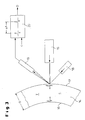
- a rod-shaped specimen 1 can be seen, for measuring the used longitudinal sound velocity c in the material of the sample body becomes.
- d. H the functional relationship about how the Speed of sound c above the temperature T of the material changes.
- the laser-ultrasonic hot-wall thickness measuring method is used which on the classical principle of ultrasonic transit time turns off. From the time for - passing through an ultrasonic pulse through the wall of the - Pipe 14 results in known sound velocity c in the material of the tube the desired wall thickness D.
- the coupling of the ultrasound in the hot wall thickness measurement with temperatures T in the range of about 1,000 ° C requires both on the excitation and the detection side non-contact, optical Methods in which the measuring head itself in a thermally safe distance can remain to the tube 14.
- High-energy light pulses in the infrared range are in the tube surface absorbed. They are of a aligned on the pipe wall, in the embodiment Flash lamp-pumped Nd: YAG laser 15 (excitation laser) - alternative can be a conventional piezoelectric technique (see Fig. 1) or EMUS (Electromagnetic Use ultrasound) technique - which generates a wavelength of 1,064 nm at a pulse duration of less than 10 ns.
- the laser 15 on the pipe surface applied energy absorbed by the pipe wall, partially leads to the evaporation of a very thin surface layer (material ablation in the nm range).
- the reflected ultrasonic pulse is generated on the tube outer surface 17 Vibrations (in the sub-miniature range), which are measured by means of a second laser 18 (detection laser) be detected without contact using the Doppler effect.
- This laser 18 can be a CW laser (continuous wave laser), namely a frequency doubled diode pumped Nd: YAG laser equipped with a Wavelength of 532 nm works and aligned to the point of excitation is.
- the low frequency compared to the light frequency ultrasonic vibration leads to a frequency modulation of the reflected light on the material surface.
- the reflected light cone which is now the "carrier" of the ultrasound signal, is transmitted via a high-intensity positive lens and an optical fiber an optical analyzer 19, d.
- a demodulator fed, in particular a confocal Fabry-Perot interferometer is used; whose output signal includes already the ultrasonic echo sequence.
- the further amplification, filtering and signal evaluation of the ultrasonic echo sequence can with a conventional electronic ultrasound evaluation unit 20 respectively.
- the output signal of the evaluation unit 20 is the wall thickness D of Pipe 14, the product of sound velocity c and measured Time interval .DELTA.t is determined, as indicated schematically in Fig. 3.
- predetermined temperature is - as can be seen in Fig. 1 - proceeded as follows:
- the long specimen 1 in the form of a round rod with 1,000 mm length and 30 mm diameter has at its one end portion 2, two reflection zones. 3 and 4, which consist of notches, which are introduced into the round bar. Both Notches 3, 4 are arranged at a precisely defined distance a, in the embodiment 100 mm. The distance a between the two notches 3, 4 forms the measuring section. The notches 3, 4 are in the embodiment in the area the first 200 mm of the sample body 1 introduced.
- the end portion 2 of the sample body 1 is placed in a furnace 7, where he on the temperature T is heated at which the speed of sound c is measured shall be.
- the remaining, unheated portion of the sample body 1 can be cooled become; shown is a coolant in a water tank 11. It can namely be provided that the unheated portion of the specimen 1, which essentially serves to guide the sound, with one end 6, as shown in FIG. 1, in which water tank 11 is located.
- an ultrasonic source 8 is arranged, wherein it This is preferably a conventional ultrasonic probe 10 in piezo technology is.
- the ultrasonic source 8 leaves a sound wave 5 (compression wave, Longitudinalwelle) in the longitudinal direction L of the sample body 1 in the direction of to run the end section 2.
- the sound wave is reflected ("error echo") and runs - from left to right in Fig. 1 - in the sample body 1 back to the end 6.
- Das reflected sound signal will turn with the conventional ultrasonic probe 10 and determines the duration between the "score echoes".
- a Ultrasonic electronics or evaluation unit 20 receives the measured time interval ⁇ t, which lies between the reflected waves at the two notches 3, 4. By quotient a / ⁇ t the sound velocity c at the temperature T determined.
- the current temperature T is detected by a sensor 21. It is up to a temperature of about 600 ° C in 100 K increments and between 600 ° C to 1200 ° C in 50 K increments.
- the screening of the temperature steps depends on the respective task from.
- the hot tube wall thickness measurement of the T-range above 600 ° C is particularly relevant, you choose in this T-range, in which too Metallurgical transformations take place in the material, the grid is relatively close meshed.
- the course of the speed of sound c is a function of the temperature T before, wherein the thermal expansion of the material is included.
- the end portion 2 of the sample body 1 also be geometrically different.
- the test section by a stepped portion .DELTA.l at the end located in the furnace 7 of the long Sample body (rod) 1 is formed.
- the absorbed by the water tank 11 End 6 of the long specimen 1 are two piezo-ultrasonic probes 10 associated with the ultrasonic electronics or -Ausncetechnik 20 are signaled verbunen.
Landscapes
- Physics & Mathematics (AREA)
- General Physics & Mathematics (AREA)
- Immunology (AREA)
- Pathology (AREA)
- Analytical Chemistry (AREA)
- Biochemistry (AREA)
- General Health & Medical Sciences (AREA)
- Life Sciences & Earth Sciences (AREA)
- Health & Medical Sciences (AREA)
- Chemical & Material Sciences (AREA)
- Optics & Photonics (AREA)
- Acoustics & Sound (AREA)
- Investigating Or Analyzing Materials By The Use Of Ultrasonic Waves (AREA)
- Length Measuring Devices Characterised By Use Of Acoustic Means (AREA)
- Measurement Of Mechanical Vibrations Or Ultrasonic Waves (AREA)
- Measuring Temperature Or Quantity Of Heat (AREA)
Abstract
Description
- einen sich in einer Längsrichtung erstreckenden Probenkörper, der aus dem zu vermessenden Werkstoff besteht, wobei der Probenkörper, vorzugsweise in einem seiner Endabschnitte, zwei Reflektionszonen in vorgegebenem Abstand aufweist;
- ein Heizmittel, insbesondere einen Ofen, mit dem zumindest ein Endabschnitt des Probenkörpers auf eine gewünschte Temperatur, bei der die Schallgeschwindigkeit ermittelt werden soll, erwärmt werden kann;
- Mittel zum Einleiten eines Ultraschallsignals in den Probenkörper;
- Mittel zum Messen des Zeitintervalls zwischen zwei Echo-Ultraschallsignalen, die der Probenkörper emittiert, die durch Reflektion des Ultraschallsignals an den beiden Reflektionszonen entstehen;
- Mittel zum Berechnen der Schallgeschwindigkeit als Quotient des Abstands und des Zeitintervalls;
- Mittel zum Kühlen zumindest des dem erwärmten Endabschnitt gegenüberliegenden Endes des Probenkörpers.
- Fig. 1
- schematisch den Aufbau einer Vorrichtung zur Messung der Schallgeschwindigkeit in einem Probenkörper;
- Fig. 2
- den Endabschnitt des Probenkörpers gemäß einer alternativen Ausgestaltung; und
- Fig. 3
- schematisch das Prinzip der Messung der Wanddicke eines heißen Rohres nach den Laser-Ultraschallverfahren, das die ermittelten Schallgeschwindigkeiten verwendet.
- 1
- Probenkörper
- 2
- Endabschnitt des Probenkörpers
- 3
- Reflektionszone
- 4
- Reflektionszone
- 5
- Ultraschallsignal
- 6
- Ende des Probenkörpers
- 7
- Heizmittel (Ofen)
- 8
- Ultraschallquelle
- 10
- Piezo-Ultraschall-Prüfkopf
- 11
- Wasserbehälter
- 14
- Rohr
- 15
- Anregungslaser
- 16
- Rohr-Innenoberfläche
- 17
- Rohr-Außenoberfläche
- 18
- Erfassungslaser
- 19
- optischer Analysator (Fabry-Perot-Interferometer)
- 20
- Ultraschall-Auswerteeinheit
- 21
- Temperatursensor
- c
- Schallgeschwindigkeit
- T
- Temperatur
- L
- Längsrichtung
- a
- Abstand
- t
- Zeitintervall
- D
- Wanddicke
- Δl
- gestufter Abschnitt
Claims (15)
- Verfahren zur Bestimmung der Schallgeschwindigkeit (c) in einem Werkstoff in Abhängigkeit von seiner Temperatur (T), das die Schritte aufweist:wobei zumindest das dem erwärmten Endabschnitt (2) gegenüberliegende Ende (6) des Probenkörpers (1) gekühlt wird.a) Bereitstellen eines aus dem Werkstoff bestehenden Probenkörpers (1) in einer Längsrichtung (L), wobei der Probenkörper (1), vorzugsweise in einem seiner Endabschnitte (2), zwei Reflektionszonen (3, 4) in vorgegebenem Abstand (a) aufweist;b) Erhitzen zumindest des Endabschnitts (2) des Probenkörpers (1) auf die Temperatur (T), bei der die Schallgeschwindigkeit (c) ermittelt werden soll;c) Einleiten eines Ultraschallsignals (5) in den Probenkörper (1);d) Messen des Zeitintervalls (t) zwischen zwei vom Probenkörper (1) emittierten Echo-Ultraschallsignalen, die durch Reflektion des Ultraschallsignals (5) an den beiden Reflektionszonen (3, 4) entstehen;e) Berechnen der Schallgeschwindigkeit (c) als Quotient des Abstands (a) und des Zeitintervalls (t),
- Verfahren nach Anspruch 1,
dadurch gekennzeichnet, dass die Schritte b) bis e) bei unterschiedlichen Temperaturen (T) wiederholt werden. - Verfahren nach Anspruch 2,
dadurch gekennzeichnet, dass das Probenmaterial Metall, insbesondere Stahl, ist und die Messung der Schallgeschwindigkeit (c) bei Temperaturen (T) zwischen Raumtemperatur und 1.200 °C erfolgt. - Verfahren nach Anspruch 3,
dadurch gekennzeichnet, dass die Messung der Schallgeschwindigkeit (c) bei Temperaturen (T) zwischen 600 °C und 1.200 °C in Schritten von 50 K erfolgt. - Verfahren nach Anspruch 3,
dadurch gekennzeichnet, dass die Messung der Schallgeschwindigkeit (c) bei Temperaturen (T) zwischen Raumtemperatur und 600 °C in Schritten von 100 K erfolgt. - Verfahren nach einem der Ansprüche 1 bis 5,
dadurch gekennzeichnet, dass der gesamte nicht erwärmte Teil des Probenkörpers (1) gekühlt wird. - Verfahren nach einem der Ansprüche 1 bis 6,
dadurch gekennzeichnet, dass das Ultraschallsignal (5) in den Probenkörper (1) an dem dem erwärmten Endabschnitt (2) gegenüberliegende Ende (6) des Probenkörpers (1) eingeleitet wird. - Verfahren nach einem der Ansprüche 1 bis 7,
dadurch gekennzeichnet, dass das Ultraschallsignal (5) in den Probenkörper (1) über ein Piezo-Ultraschallelement mit Wasserankopplung eingeleitet wird. - Vorrichtung zur Bestimmung der Schallgeschwindigkeit (c) in einem Werkstoff in Abhängigkeit von seiner Temperatur (T), insbesondere zur Durchführung des Verfahrens nach einem der Ansprüche 1 bis 8,
gekennzeichnet durcheinen aus dem Werkstoff bestehenden, in einer Längsrichtung (L) bereitgestellten Probenkörper (1) von großer Länge, der vorzugsweise in einem seiner Endabschnitte (2) zwei Reflektionszonen (3, 4) in vorgegebenem Abstand (a) aufweist,Heizmittel (7), insbesondere einen Ofen, das zumindest einen Endabschnitt (2) des Probenkörpers (1) auf eine gewünschte Temperatur (T), bei der die Schallgeschwindigkeit (c) ermittelt werden soll, erwärmt,Mittel (8) zum Einleiten eines Ultraschallsignals (5) in den Probenkörper (1),Mittel (9) zum Messen des Zeitintervalls (t) zwischen zwei Echo-Ultraschallsignalen, die der Probenkörper (1) emittiert, die durch Reflektion des Ultraschallsignals (5) an den beiden Reflektionszonen (3, 4) entstehen,Mittel (10) zum Berechnen der Schallgeschwindigkeit (c) als Quotient des Abstands (a) und des Zeitintervalls ( t) undMittel (11) zum Kühlen zumindest des dem erwärmten Endabschnitt (2) gegenüberliegenden Endes (6) des Probenkörpers (1). - Vorrichtung nach Anspruch 9,
dadurch gekennzeichnet, dass der Probenkörper (1) als ein Rundstab oder Flachstab aus dem Probenwerkstoff ausgebildet ist. - Vorrichtung nach Anspruch 9 oder 10,
dadurch gekennzeichnet, dass die Reflektionszonen (3, 4) als in den Probenkörper (1) eingearbeitete Kerben ausgebildet sind. - Vorrichtung nach Anspruch 9 oder 10,
dadurch gekennzeichnet, dass die Reflektionszonen (3, 4) durch eine Querschnittsveränderung im Probenkörper (1) ausgebildet sind. - Vorrichtung nach Anspruch 12,
dadurch gekennzeichnet, dass die Querschnittsveränderung stufenförmig ausgebildet ist. - Vorrichtung nach einem der Ansprüche 9 bis 13,
dadurch gekennzeichnet, dass der Probenkörper (1) eine Länge von 750 bis 1.250 mm aufweist, wobei die beiden Reflektionszonen (3, 4) in Form von Kerben im einen Endbereich (2) des Probenkörpers (1) in einem Abstand von 50 bis 200 mm, vorzugsweise in einem Abstand von 100 mm, angeordnet sind. - Vorrichtung nach Anspruch 14,
dadurch gekennzeichnet, dass der Probenkörper (1) als Rundstab mit einem Durchmesser zwischen 15 mm und 50 mm, vorzugsweise mit einem Durchmesser von 30 mm, ausgebildet ist.
Applications Claiming Priority (2)
| Application Number | Priority Date | Filing Date | Title |
|---|---|---|---|
| DE10223786A DE10223786C1 (de) | 2002-05-29 | 2002-05-29 | Verfahren und Vorrichtung zur Bestimmung der Schallgeschwindigkeit in einem Werkstoff |
| DE10223786 | 2002-05-29 |
Publications (2)
| Publication Number | Publication Date |
|---|---|
| EP1367390A1 true EP1367390A1 (de) | 2003-12-03 |
| EP1367390B1 EP1367390B1 (de) | 2007-09-19 |
Family
ID=7714588
Family Applications (1)
| Application Number | Title | Priority Date | Filing Date |
|---|---|---|---|
| EP03010646A Expired - Lifetime EP1367390B1 (de) | 2002-05-29 | 2003-05-13 | Verfahren und Vorrichtung zur Bestimmung der Schallgeschwindigkeit in einem Werkstoff in Abhängigkeit der Temperatur |
Country Status (6)
| Country | Link |
|---|---|
| US (1) | US6810742B2 (de) |
| EP (1) | EP1367390B1 (de) |
| AT (1) | ATE373821T1 (de) |
| CA (1) | CA2428384C (de) |
| DE (2) | DE10223786C1 (de) |
| ES (1) | ES2290380T3 (de) |
Families Citing this family (12)
| Publication number | Priority date | Publication date | Assignee | Title |
|---|---|---|---|---|
| RU2235317C2 (ru) * | 2001-01-09 | 2004-08-27 | Открытое акционерное общество "Предприятие по наладке, совершенствованию технологии и эксплуатации электростанций и сетей "УралОРГРЭС" | Способ определения состояния металла гибов высокотемпературных трубопроводов, работающих в условиях ползучести, прогнозирование его остаточного ресурса и устройство для его осуществления |
| US7614302B2 (en) | 2005-08-01 | 2009-11-10 | Baker Hughes Incorporated | Acoustic fluid analysis method |
| JP4826949B2 (ja) † | 2006-09-11 | 2011-11-30 | 住友金属工業株式会社 | 継目無管の製造状況モニタリング装置及び方法並びに継目無管製造設備 |
| US7933027B1 (en) * | 2008-06-27 | 2011-04-26 | The United States Of America As Represented By The Administrator Of National Aeronautics And Space Administration | Processing waveform-based NDE |
| US7876423B1 (en) * | 2008-06-27 | 2011-01-25 | The United States Of America As Represented By The National Aeronautics And Space Administration | Simultaneous noncontact precision imaging of microstructural and thickness variation in dielectric materials using terahertz energy |
| RU2613485C2 (ru) * | 2015-06-29 | 2017-03-16 | Федеральное государственное бюджетное учреждение науки Институт радиотехники и электроники им. В.А. Котельникова Российской академии наук | Способ измерения вертикального распределения скорости звука в воде |
| CN106546662B (zh) * | 2016-10-31 | 2019-11-08 | 中国科学院地质与地球物理研究所 | 一种饱水泥岩高压排水条件下岩石声波速度测试方法 |
| CN111721392A (zh) * | 2020-07-22 | 2020-09-29 | 西安热工研究院有限公司 | 一种用于测量高温下表面波声速的系统及方法 |
| CN112880802A (zh) * | 2021-03-05 | 2021-06-01 | 西安热工研究院有限公司 | 一种用于测量高温下柱面导波声速的装置及方法 |
| CN114384155A (zh) * | 2022-01-12 | 2022-04-22 | 重庆医科大学 | 用于测量波导管内介质声速的测量系统及声速测量方法 |
| CN119063869B (zh) * | 2024-11-06 | 2025-01-24 | 中国空气动力研究与发展中心计算空气动力研究所 | 一种金属基复合材料结构内部温度场的超声测量方法 |
| CN119533630B (zh) * | 2024-11-21 | 2025-07-15 | 天津大学 | 一种声速测量装置及方法 |
Citations (2)
| Publication number | Priority date | Publication date | Assignee | Title |
|---|---|---|---|---|
| DE1248347B (de) * | 1962-02-07 | 1967-08-24 | Euratom | Verfahren zur Messung der Schallgeschwindigkeit in einem Koerper |
| US4762425A (en) * | 1987-10-15 | 1988-08-09 | Parthasarathy Shakkottai | System for temperature profile measurement in large furnances and kilns and method therefor |
Family Cites Families (12)
| Publication number | Priority date | Publication date | Assignee | Title |
|---|---|---|---|---|
| US3943755A (en) * | 1974-10-22 | 1976-03-16 | Tokyo Shibaura Electric Co., Ltd. | Method and apparatus for measuring the magnitude of a clamping load applied to a laminated iron core of an electric machine |
| US4246793A (en) * | 1979-02-08 | 1981-01-27 | Battelle Development Corporation | Nondestructive testing |
| GB2114297A (en) * | 1982-02-10 | 1983-08-17 | Euratom | Very high temperature ultrasonic thermometer |
| US4567770A (en) * | 1983-03-21 | 1986-02-04 | Sonic Instruments Inc. | Ultrasonic transducer apparatus and method for high temperature measurements |
| US5648611A (en) * | 1993-12-22 | 1997-07-15 | The Timken Company | Process for measuring the case depth of case-carburized steel |
| US5379270A (en) * | 1994-03-25 | 1995-01-03 | The United States Of America As Represented By The Secretary Of The Navy | Acoustic-optic sound velocity profiler |
| US6175416B1 (en) * | 1996-08-06 | 2001-01-16 | Brown University Research Foundation | Optical stress generator and detector |
| US5684252A (en) * | 1996-07-15 | 1997-11-04 | Sonoscan, Inc. | Method and apparatus for ultrasonic inspection of electronic components |
| CA2187957C (en) | 1996-10-16 | 2003-06-03 | Cheng-Kuei Jen | Ultrasonic sensors for on-line monitoring of castings and molding processes at elevated temperatures |
| IT1298331B1 (it) | 1998-03-04 | 1999-12-20 | Mannesmann Ag | Procedimento per la realizzazione di tubi senza saldatura |
| US6069703A (en) * | 1998-05-28 | 2000-05-30 | Active Impulse Systems, Inc. | Method and device for simultaneously measuring the thickness of multiple thin metal films in a multilayer structure |
| US6628404B1 (en) * | 2000-11-21 | 2003-09-30 | Sandia Corporation | Acoustic sensor for real-time control for the inductive heating process |
-
2002
- 2002-05-29 DE DE10223786A patent/DE10223786C1/de not_active Expired - Fee Related
-
2003
- 2003-05-08 CA CA002428384A patent/CA2428384C/en not_active Expired - Fee Related
- 2003-05-13 EP EP03010646A patent/EP1367390B1/de not_active Expired - Lifetime
- 2003-05-13 DE DE50308207T patent/DE50308207D1/de not_active Expired - Lifetime
- 2003-05-13 AT AT03010646T patent/ATE373821T1/de not_active IP Right Cessation
- 2003-05-13 ES ES03010646T patent/ES2290380T3/es not_active Expired - Lifetime
- 2003-05-28 US US10/446,503 patent/US6810742B2/en not_active Expired - Lifetime
Patent Citations (2)
| Publication number | Priority date | Publication date | Assignee | Title |
|---|---|---|---|---|
| DE1248347B (de) * | 1962-02-07 | 1967-08-24 | Euratom | Verfahren zur Messung der Schallgeschwindigkeit in einem Koerper |
| US4762425A (en) * | 1987-10-15 | 1988-08-09 | Parthasarathy Shakkottai | System for temperature profile measurement in large furnances and kilns and method therefor |
Non-Patent Citations (1)
| Title |
|---|
| HE P: "Simultaneous measurement of sound velocity and wall thickness of a tube", ULTRASONICS, IPC SCIENCE AND TECHNOLOGY PRESS LTD. GUILDFORD, GB, vol. 39, no. 6, October 2001 (2001-10-01), pages 407 - 411, XP004324322, ISSN: 0041-624X * |
Also Published As
| Publication number | Publication date |
|---|---|
| CA2428384C (en) | 2006-09-05 |
| US20030221490A1 (en) | 2003-12-04 |
| EP1367390B1 (de) | 2007-09-19 |
| DE50308207D1 (de) | 2007-10-31 |
| CA2428384A1 (en) | 2003-11-29 |
| US6810742B2 (en) | 2004-11-02 |
| ES2290380T3 (es) | 2008-02-16 |
| DE10223786C1 (de) | 2003-07-10 |
| ATE373821T1 (de) | 2007-10-15 |
Similar Documents
| Publication | Publication Date | Title |
|---|---|---|
| DE60132389T2 (de) | Herstellungsverfahren für ein stranggegossenes Stahlprodukt | |
| EP0653061B1 (de) | Verfahren zur bewertung von schweissverbindungen | |
| DE10084306B4 (de) | Ultraschallerfassungsgerät und ein dieses verwendendes Ultraschallerfassungsverfahren | |
| DE3781296T2 (de) | Messung von oxidkesselstein an den innenflaechen von kesselroehren. | |
| EP1367390B1 (de) | Verfahren und Vorrichtung zur Bestimmung der Schallgeschwindigkeit in einem Werkstoff in Abhängigkeit der Temperatur | |
| EP1369664B1 (de) | Verfahren und Vorrichtung zur Bestimmung der Exzentrizität eines Hohlblocks | |
| DE2617246A1 (de) | Vorrichtung zur praezisionsmessung von abmessungen mittels ultraschall | |
| DE102008027228B4 (de) | Verfahren und Vorrichtung zur zerstörungsfreien Ultraschalluntersuchung eines Prüfstücks mit zueinander gewinkelten, ebenen Oberflächen | |
| DE102009004946B4 (de) | Verfahren und Vorrichtung zur Messung der Temperatur eines plastifizierten Kunststoffs am Ausgang eines Extruders | |
| DE102011115691B4 (de) | Verfahren zur Ermittlung der Viskosität eines strömenden oder ruhenden Fluids | |
| EP1378299A1 (de) | Verfahren und Vorrichtung zur Bestimmung der Exzentrizität eines Hohlblocks | |
| EP1391687B1 (de) | Vorrichtung zur Messung der Wanddicke eines Rohres in einem Rohrwalzwerk | |
| WO2008019948A1 (de) | Verfahren zum prüfen der gefügestruktur einer schweissverbindung | |
| DE19640859B4 (de) | Verfahren und Vorrichtung zur zerstörungsfreien Feststellung des Werkstoffzustands in Bauteilen | |
| EP1850979B1 (de) | Verfahren und vorrichtung zur überwachung des fertigungsprozesses zur herstellung von warmgefertigten rohren aus stahl | |
| DE4305064C1 (de) | Verfahren und Vorrichtung zur gleichzeitigen zerstörungsfreien Charakterisierung mehrerer Kennwerte oberflächenmodifizierter Werkstoffe | |
| EP1762841A1 (de) | Verfahren und Einrichtung zur Ultraschallprüfung eines Werkstückes mit einer unebenen Oberfläche | |
| DE102006028369B4 (de) | Verfahren und Vorrichtung zur Prozesskontrolle beim Walzen von Metallen | |
| DE2939480A1 (de) | Verfahren zur ermittlung von rissen u.dgl. in einem rohr mit hilfe von ultraschall | |
| DE102014104914B4 (de) | Vorrichtung und Verfahren zur zerstörungsfreien Prüfung eines Prüflings mittels Ultraschall nach der Vergleichskörpermethode | |
| DD293285A5 (de) | Verfahren und vorrichtung zum stranggiessen duenner metallischer gegenstaende | |
| DE4239159C2 (de) | Vorrichtung zum zerstörungsfreien Messen der Dicke einer Härteschicht | |
| DE10102628A1 (de) | Verfahren und Messeinrichtung zur Vermessung einer honbearbeiteten Bohrung in einem Werstück | |
| DE102017204468A1 (de) | Verfahren zum Erfassen einer Temperatur eines aus mehreren Schichten aufgebauten Schichtmaterials sowie Thermometer | |
| DE69111307T2 (de) | Verfahren zur Feststellung von Fehlern auf Metallrohren mit schraubenlinienförmig verlaufenden Innenrippen. |
Legal Events
| Date | Code | Title | Description |
|---|---|---|---|
| PUAI | Public reference made under article 153(3) epc to a published international application that has entered the european phase |
Free format text: ORIGINAL CODE: 0009012 |
|
| AK | Designated contracting states |
Kind code of ref document: A1 Designated state(s): AT BE BG CH CY CZ DE DK EE ES FI FR GB GR HU IE IT LI LU MC NL PT RO SE SI SK TR |
|
| AX | Request for extension of the european patent |
Extension state: AL LT LV MK |
|
| RIN1 | Information on inventor provided before grant (corrected) |
Inventor name: DEPPE, GERD-JOACHIM DR. Inventor name: SAUERLAND, MARTIN |
|
| 17P | Request for examination filed |
Effective date: 20040525 |
|
| AKX | Designation fees paid |
Designated state(s): AT BE BG CH CY CZ DE DK EE ES FI FR GB GR HU IE IT LI LU MC NL PT RO SE SI SK TR |
|
| GRAP | Despatch of communication of intention to grant a patent |
Free format text: ORIGINAL CODE: EPIDOSNIGR1 |
|
| RIC1 | Information provided on ipc code assigned before grant |
Ipc: G01N 29/07 20060101AFI20070309BHEP Ipc: G01H 5/00 20060101ALI20070309BHEP |
|
| R17C | First examination report despatched (corrected) |
Effective date: 20070321 |
|
| GRAS | Grant fee paid |
Free format text: ORIGINAL CODE: EPIDOSNIGR3 |
|
| GRAA | (expected) grant |
Free format text: ORIGINAL CODE: 0009210 |
|
| AK | Designated contracting states |
Kind code of ref document: B1 Designated state(s): AT BE BG CH CY CZ DE DK EE ES FI FR GB GR HU IE IT LI LU MC NL PT RO SE SI SK TR |
|
| REG | Reference to a national code |
Ref country code: GB Ref legal event code: FG4D Free format text: NOT ENGLISH |
|
| REG | Reference to a national code |
Ref country code: CH Ref legal event code: EP |
|
| REF | Corresponds to: |
Ref document number: 50308207 Country of ref document: DE Date of ref document: 20071031 Kind code of ref document: P |
|
| REG | Reference to a national code |
Ref country code: SE Ref legal event code: TRGR |
|
| REG | Reference to a national code |
Ref country code: IE Ref legal event code: FG4D Free format text: LANGUAGE OF EP DOCUMENT: GERMAN |
|
| PG25 | Lapsed in a contracting state [announced via postgrant information from national office to epo] |
Ref country code: FI Free format text: LAPSE BECAUSE OF FAILURE TO SUBMIT A TRANSLATION OF THE DESCRIPTION OR TO PAY THE FEE WITHIN THE PRESCRIBED TIME-LIMIT Effective date: 20070919 |
|
| REG | Reference to a national code |
Ref country code: ES Ref legal event code: FG2A Ref document number: 2290380 Country of ref document: ES Kind code of ref document: T3 |
|
| NLV1 | Nl: lapsed or annulled due to failure to fulfill the requirements of art. 29p and 29m of the patents act | ||
| ET | Fr: translation filed | ||
| PG25 | Lapsed in a contracting state [announced via postgrant information from national office to epo] |
Ref country code: NL Free format text: LAPSE BECAUSE OF FAILURE TO SUBMIT A TRANSLATION OF THE DESCRIPTION OR TO PAY THE FEE WITHIN THE PRESCRIBED TIME-LIMIT Effective date: 20070919 Ref country code: GR Free format text: LAPSE BECAUSE OF FAILURE TO SUBMIT A TRANSLATION OF THE DESCRIPTION OR TO PAY THE FEE WITHIN THE PRESCRIBED TIME-LIMIT Effective date: 20071220 |
|
| REG | Reference to a national code |
Ref country code: IE Ref legal event code: FD4D |
|
| PG25 | Lapsed in a contracting state [announced via postgrant information from national office to epo] |
Ref country code: PT Free format text: LAPSE BECAUSE OF FAILURE TO SUBMIT A TRANSLATION OF THE DESCRIPTION OR TO PAY THE FEE WITHIN THE PRESCRIBED TIME-LIMIT Effective date: 20080219 Ref country code: GB Free format text: LAPSE BECAUSE OF FAILURE TO SUBMIT A TRANSLATION OF THE DESCRIPTION OR TO PAY THE FEE WITHIN THE PRESCRIBED TIME-LIMIT Effective date: 20070919 |
|
| PG25 | Lapsed in a contracting state [announced via postgrant information from national office to epo] |
Ref country code: RO Free format text: LAPSE BECAUSE OF FAILURE TO SUBMIT A TRANSLATION OF THE DESCRIPTION OR TO PAY THE FEE WITHIN THE PRESCRIBED TIME-LIMIT Effective date: 20070919 |
|
| PLBE | No opposition filed within time limit |
Free format text: ORIGINAL CODE: 0009261 |
|
| STAA | Information on the status of an ep patent application or granted ep patent |
Free format text: STATUS: NO OPPOSITION FILED WITHIN TIME LIMIT |
|
| PG25 | Lapsed in a contracting state [announced via postgrant information from national office to epo] |
Ref country code: DK Free format text: LAPSE BECAUSE OF FAILURE TO SUBMIT A TRANSLATION OF THE DESCRIPTION OR TO PAY THE FEE WITHIN THE PRESCRIBED TIME-LIMIT Effective date: 20070919 |
|
| 26N | No opposition filed |
Effective date: 20080620 |
|
| PG25 | Lapsed in a contracting state [announced via postgrant information from national office to epo] |
Ref country code: IE Free format text: LAPSE BECAUSE OF FAILURE TO SUBMIT A TRANSLATION OF THE DESCRIPTION OR TO PAY THE FEE WITHIN THE PRESCRIBED TIME-LIMIT Effective date: 20070919 |
|
| BERE | Be: lapsed |
Owner name: SMS MEER G.M.B.H. Effective date: 20080531 |
|
| PG25 | Lapsed in a contracting state [announced via postgrant information from national office to epo] |
Ref country code: MC Free format text: LAPSE BECAUSE OF NON-PAYMENT OF DUE FEES Effective date: 20080531 |
|
| REG | Reference to a national code |
Ref country code: CH Ref legal event code: PL |
|
| PG25 | Lapsed in a contracting state [announced via postgrant information from national office to epo] |
Ref country code: LI Free format text: LAPSE BECAUSE OF NON-PAYMENT OF DUE FEES Effective date: 20080531 Ref country code: EE Free format text: LAPSE BECAUSE OF FAILURE TO SUBMIT A TRANSLATION OF THE DESCRIPTION OR TO PAY THE FEE WITHIN THE PRESCRIBED TIME-LIMIT Effective date: 20070919 Ref country code: CH Free format text: LAPSE BECAUSE OF NON-PAYMENT OF DUE FEES Effective date: 20080531 |
|
| PG25 | Lapsed in a contracting state [announced via postgrant information from national office to epo] |
Ref country code: BE Free format text: LAPSE BECAUSE OF NON-PAYMENT OF DUE FEES Effective date: 20080531 |
|
| PG25 | Lapsed in a contracting state [announced via postgrant information from national office to epo] |
Ref country code: SI Free format text: LAPSE BECAUSE OF FAILURE TO SUBMIT A TRANSLATION OF THE DESCRIPTION OR TO PAY THE FEE WITHIN THE PRESCRIBED TIME-LIMIT Effective date: 20070919 |
|
| PG25 | Lapsed in a contracting state [announced via postgrant information from national office to epo] |
Ref country code: CY Free format text: LAPSE BECAUSE OF FAILURE TO SUBMIT A TRANSLATION OF THE DESCRIPTION OR TO PAY THE FEE WITHIN THE PRESCRIBED TIME-LIMIT Effective date: 20070919 |
|
| PG25 | Lapsed in a contracting state [announced via postgrant information from national office to epo] |
Ref country code: AT Free format text: LAPSE BECAUSE OF NON-PAYMENT OF DUE FEES Effective date: 20080513 Ref country code: BG Free format text: LAPSE BECAUSE OF FAILURE TO SUBMIT A TRANSLATION OF THE DESCRIPTION OR TO PAY THE FEE WITHIN THE PRESCRIBED TIME-LIMIT Effective date: 20071219 |
|
| PG25 | Lapsed in a contracting state [announced via postgrant information from national office to epo] |
Ref country code: HU Free format text: LAPSE BECAUSE OF FAILURE TO SUBMIT A TRANSLATION OF THE DESCRIPTION OR TO PAY THE FEE WITHIN THE PRESCRIBED TIME-LIMIT Effective date: 20080320 Ref country code: LU Free format text: LAPSE BECAUSE OF NON-PAYMENT OF DUE FEES Effective date: 20080513 |
|
| PG25 | Lapsed in a contracting state [announced via postgrant information from national office to epo] |
Ref country code: TR Free format text: LAPSE BECAUSE OF FAILURE TO SUBMIT A TRANSLATION OF THE DESCRIPTION OR TO PAY THE FEE WITHIN THE PRESCRIBED TIME-LIMIT Effective date: 20070919 |
|
| REG | Reference to a national code |
Ref country code: DE Ref legal event code: R082 Ref document number: 50308207 Country of ref document: DE Representative=s name: HEMMERICH & KOLLEGEN, DE Ref country code: DE Ref legal event code: R081 Ref document number: 50308207 Country of ref document: DE Owner name: SMS GROUP GMBH, DE Free format text: FORMER OWNER: SMS MEER GMBH, 41069 MOENCHENGLADBACH, DE |
|
| REG | Reference to a national code |
Ref country code: FR Ref legal event code: PLFP Year of fee payment: 14 |
|
| REG | Reference to a national code |
Ref country code: FR Ref legal event code: PLFP Year of fee payment: 15 |
|
| PGFP | Annual fee paid to national office [announced via postgrant information from national office to epo] |
Ref country code: FR Payment date: 20170523 Year of fee payment: 15 Ref country code: DE Payment date: 20170523 Year of fee payment: 15 |
|
| PGFP | Annual fee paid to national office [announced via postgrant information from national office to epo] |
Ref country code: IT Payment date: 20170526 Year of fee payment: 15 Ref country code: ES Payment date: 20170627 Year of fee payment: 15 Ref country code: SE Payment date: 20170519 Year of fee payment: 15 |
|
| PGFP | Annual fee paid to national office [announced via postgrant information from national office to epo] |
Ref country code: CZ Payment date: 20180510 Year of fee payment: 16 Ref country code: SK Payment date: 20180510 Year of fee payment: 16 |
|
| REG | Reference to a national code |
Ref country code: DE Ref legal event code: R119 Ref document number: 50308207 Country of ref document: DE |
|
| REG | Reference to a national code |
Ref country code: SE Ref legal event code: EUG |
|
| PG25 | Lapsed in a contracting state [announced via postgrant information from national office to epo] |
Ref country code: SE Free format text: LAPSE BECAUSE OF NON-PAYMENT OF DUE FEES Effective date: 20180514 |
|
| PG25 | Lapsed in a contracting state [announced via postgrant information from national office to epo] |
Ref country code: FR Free format text: LAPSE BECAUSE OF NON-PAYMENT OF DUE FEES Effective date: 20180531 Ref country code: IT Free format text: LAPSE BECAUSE OF NON-PAYMENT OF DUE FEES Effective date: 20180513 Ref country code: DE Free format text: LAPSE BECAUSE OF NON-PAYMENT OF DUE FEES Effective date: 20181201 |
|
| REG | Reference to a national code |
Ref country code: ES Ref legal event code: FD2A Effective date: 20190913 |
|
| PG25 | Lapsed in a contracting state [announced via postgrant information from national office to epo] |
Ref country code: ES Free format text: LAPSE BECAUSE OF NON-PAYMENT OF DUE FEES Effective date: 20180514 |
|
| PG25 | Lapsed in a contracting state [announced via postgrant information from national office to epo] |
Ref country code: CZ Free format text: LAPSE BECAUSE OF NON-PAYMENT OF DUE FEES Effective date: 20190513 Ref country code: SK Free format text: LAPSE BECAUSE OF NON-PAYMENT OF DUE FEES Effective date: 20190513 |
|
| REG | Reference to a national code |
Ref country code: SK Ref legal event code: MM4A Ref document number: E 2772 Country of ref document: SK Effective date: 20190513 |