EP1367390A1 - Method and apparatus for determination of sound velocity of a material depending on the temperature - Google Patents
Method and apparatus for determination of sound velocity of a material depending on the temperature Download PDFInfo
- Publication number
- EP1367390A1 EP1367390A1 EP03010646A EP03010646A EP1367390A1 EP 1367390 A1 EP1367390 A1 EP 1367390A1 EP 03010646 A EP03010646 A EP 03010646A EP 03010646 A EP03010646 A EP 03010646A EP 1367390 A1 EP1367390 A1 EP 1367390A1
- Authority
- EP
- European Patent Office
- Prior art keywords
- sample body
- sound
- speed
- temperature
- sample
- Prior art date
- Legal status (The legal status is an assumption and is not a legal conclusion. Google has not performed a legal analysis and makes no representation as to the accuracy of the status listed.)
- Granted
Links
- 239000000463 material Substances 0.000 title claims abstract description 23
- 238000000034 method Methods 0.000 title claims description 33
- 238000002604 ultrasonography Methods 0.000 claims abstract description 14
- 239000000523 sample Substances 0.000 claims description 59
- 238000005259 measurement Methods 0.000 claims description 12
- XLYOFNOQVPJJNP-UHFFFAOYSA-N water Substances O XLYOFNOQVPJJNP-UHFFFAOYSA-N 0.000 claims description 6
- 238000010438 heat treatment Methods 0.000 claims description 5
- 229910000831 Steel Inorganic materials 0.000 claims description 4
- 239000010959 steel Substances 0.000 claims description 4
- 230000008859 change Effects 0.000 claims description 3
- 238000001816 cooling Methods 0.000 claims description 3
- 230000008878 coupling Effects 0.000 claims description 3
- 238000010168 coupling process Methods 0.000 claims description 3
- 238000005859 coupling reaction Methods 0.000 claims description 3
- 239000002184 metal Substances 0.000 claims description 2
- 229910052751 metal Inorganic materials 0.000 claims description 2
- 238000005096 rolling process Methods 0.000 description 7
- 238000011156 evaluation Methods 0.000 description 5
- 230000005284 excitation Effects 0.000 description 4
- 230000003287 optical effect Effects 0.000 description 3
- 241000271559 Dromaiidae Species 0.000 description 2
- 230000009286 beneficial effect Effects 0.000 description 2
- 238000001514 detection method Methods 0.000 description 2
- 238000005516 engineering process Methods 0.000 description 2
- 238000001704 evaporation Methods 0.000 description 2
- 230000008020 evaporation Effects 0.000 description 2
- 238000004519 manufacturing process Methods 0.000 description 2
- 230000008569 process Effects 0.000 description 2
- 230000009467 reduction Effects 0.000 description 2
- 239000007858 starting material Substances 0.000 description 2
- 244000089486 Phragmites australis subsp australis Species 0.000 description 1
- 238000002679 ablation Methods 0.000 description 1
- 230000003321 amplification Effects 0.000 description 1
- 230000006835 compression Effects 0.000 description 1
- 238000007906 compression Methods 0.000 description 1
- 238000010276 construction Methods 0.000 description 1
- 239000002826 coolant Substances 0.000 description 1
- 230000003247 decreasing effect Effects 0.000 description 1
- 230000001419 dependent effect Effects 0.000 description 1
- 238000013461 design Methods 0.000 description 1
- 238000011161 development Methods 0.000 description 1
- 238000002592 echocardiography Methods 0.000 description 1
- 230000000694 effects Effects 0.000 description 1
- 238000001914 filtration Methods 0.000 description 1
- 238000011835 investigation Methods 0.000 description 1
- 229910001338 liquidmetal Inorganic materials 0.000 description 1
- 238000012544 monitoring process Methods 0.000 description 1
- 238000003199 nucleic acid amplification method Methods 0.000 description 1
- 239000013307 optical fiber Substances 0.000 description 1
- 230000002093 peripheral effect Effects 0.000 description 1
- 238000006722 reduction reaction Methods 0.000 description 1
- 238000012216 screening Methods 0.000 description 1
- 238000004513 sizing Methods 0.000 description 1
- 230000005236 sound signal Effects 0.000 description 1
- 239000002344 surface layer Substances 0.000 description 1
- 238000012360 testing method Methods 0.000 description 1
- 230000009466 transformation Effects 0.000 description 1
- 238000000844 transformation Methods 0.000 description 1
- 238000009683 ultrasonic thickness measurement Methods 0.000 description 1
Images


Classifications
-
- G—PHYSICS
- G01—MEASURING; TESTING
- G01H—MEASUREMENT OF MECHANICAL VIBRATIONS OR ULTRASONIC, SONIC OR INFRASONIC WAVES
- G01H5/00—Measuring propagation velocity of ultrasonic, sonic or infrasonic waves, e.g. of pressure waves
-
- G—PHYSICS
- G01—MEASURING; TESTING
- G01N—INVESTIGATING OR ANALYSING MATERIALS BY DETERMINING THEIR CHEMICAL OR PHYSICAL PROPERTIES
- G01N29/00—Investigating or analysing materials by the use of ultrasonic, sonic or infrasonic waves; Visualisation of the interior of objects by transmitting ultrasonic or sonic waves through the object
- G01N29/04—Analysing solids
- G01N29/07—Analysing solids by measuring propagation velocity or propagation time of acoustic waves
-
- G—PHYSICS
- G01—MEASURING; TESTING
- G01N—INVESTIGATING OR ANALYSING MATERIALS BY DETERMINING THEIR CHEMICAL OR PHYSICAL PROPERTIES
- G01N29/00—Investigating or analysing materials by the use of ultrasonic, sonic or infrasonic waves; Visualisation of the interior of objects by transmitting ultrasonic or sonic waves through the object
- G01N29/22—Details, e.g. general constructional or apparatus details
- G01N29/228—Details, e.g. general constructional or apparatus details related to high temperature conditions
-
- G—PHYSICS
- G01—MEASURING; TESTING
- G01N—INVESTIGATING OR ANALYSING MATERIALS BY DETERMINING THEIR CHEMICAL OR PHYSICAL PROPERTIES
- G01N29/00—Investigating or analysing materials by the use of ultrasonic, sonic or infrasonic waves; Visualisation of the interior of objects by transmitting ultrasonic or sonic waves through the object
- G01N29/22—Details, e.g. general constructional or apparatus details
- G01N29/24—Probes
- G01N29/2418—Probes using optoacoustic interaction with the material, e.g. laser radiation, photoacoustics
-
- G—PHYSICS
- G01—MEASURING; TESTING
- G01N—INVESTIGATING OR ANALYSING MATERIALS BY DETERMINING THEIR CHEMICAL OR PHYSICAL PROPERTIES
- G01N29/00—Investigating or analysing materials by the use of ultrasonic, sonic or infrasonic waves; Visualisation of the interior of objects by transmitting ultrasonic or sonic waves through the object
- G01N29/22—Details, e.g. general constructional or apparatus details
- G01N29/32—Arrangements for suppressing undesired influences, e.g. temperature or pressure variations, compensating for signal noise
- G01N29/326—Arrangements for suppressing undesired influences, e.g. temperature or pressure variations, compensating for signal noise compensating for temperature variations
-
- G—PHYSICS
- G01—MEASURING; TESTING
- G01N—INVESTIGATING OR ANALYSING MATERIALS BY DETERMINING THEIR CHEMICAL OR PHYSICAL PROPERTIES
- G01N2291/00—Indexing codes associated with group G01N29/00
- G01N2291/01—Indexing codes associated with the measuring variable
- G01N2291/011—Velocity or travel time
-
- G—PHYSICS
- G01—MEASURING; TESTING
- G01N—INVESTIGATING OR ANALYSING MATERIALS BY DETERMINING THEIR CHEMICAL OR PHYSICAL PROPERTIES
- G01N2291/00—Indexing codes associated with group G01N29/00
- G01N2291/02—Indexing codes associated with the analysed material
- G01N2291/028—Material parameters
- G01N2291/02854—Length, thickness
-
- G—PHYSICS
- G01—MEASURING; TESTING
- G01N—INVESTIGATING OR ANALYSING MATERIALS BY DETERMINING THEIR CHEMICAL OR PHYSICAL PROPERTIES
- G01N2291/00—Indexing codes associated with group G01N29/00
- G01N2291/02—Indexing codes associated with the analysed material
- G01N2291/028—Material parameters
- G01N2291/02881—Temperature
-
- G—PHYSICS
- G01—MEASURING; TESTING
- G01N—INVESTIGATING OR ANALYSING MATERIALS BY DETERMINING THEIR CHEMICAL OR PHYSICAL PROPERTIES
- G01N2291/00—Indexing codes associated with group G01N29/00
- G01N2291/04—Wave modes and trajectories
- G01N2291/042—Wave modes
- G01N2291/0421—Longitudinal waves
-
- G—PHYSICS
- G01—MEASURING; TESTING
- G01N—INVESTIGATING OR ANALYSING MATERIALS BY DETERMINING THEIR CHEMICAL OR PHYSICAL PROPERTIES
- G01N2291/00—Indexing codes associated with group G01N29/00
- G01N2291/04—Wave modes and trajectories
- G01N2291/044—Internal reflections (echoes), e.g. on walls or defects
Definitions
- the invention relates to a method for determining the speed of sound in a material as a function of its temperature and a device, in particular for carrying out the method.
- the pipe to be processed passes through a rolling train, in the conveying direction the tube in succession a number of rolling stands are arranged.
- a number of rolling stands are arranged in each Roll stand.
- the pipe in each case Contact a defined peripheral section.
- it works in everyone Roll stand several, for example three, rolling together so that the pipe is contacted over substantially the entire circumference of the rollers.
- the tube is thus rolled to a reduced diameter while on brought a precise shape.
- the tube should have an ideal shape after rolling, d. H. the cylindrical one Contour of the outer circumference and the inner circumference should be two concentric Form circles. In fact, there are always tolerances in the finished pipe, so that a certain eccentricity of the circular contour of the inner circumference relative to that the outer circumference is present.
- the decisive quality parameter in pipe production is the pipe wall thickness, which is measured and monitored in the production process.
- the wall thickness of hot tubes are known laser ultrasonic measuring method.
- Ultrasonic thickness measurement method after the pulse echo method determine over the Transit time measurement of an ultrasonic pulse the wall thickness.
- Speed of sound in the material at the present temperature of the pipe be known.
- the speed of sound is both material and temperature dependent.
- a method of measuring the speed of sound in dependence from the temperature is known from DE-PS 12 48 347.
- Another way to determine the speed of sound at a given Temperature provides that a tube sample with known wall thickness to the desired Temperature is heated and with a wall thickness gauge after the laser ultrasonic hot wall thickness measuring method (pulse echo method) works, is measured. Due to the known wall thickness can after measurement the time interval between signal and echo on the speed of sound be recalculated at the present temperature.
- the invention is therefore based on the object, a method and an associated To provide device, with or with the above disadvantages can be overcome. It should be possible in a simple and precise manner the longitudinal speed of sound in a material at given Temperature to determine.
- the two reflection zones are located in one of the end sections the sample body, wherein substantially only this end portion uniformly is heated.
- the cooling of the heated end portion opposite End of the specimen can also be beneficial to the whole unheated Part of the specimen can be provided.
- the introduction of the ultrasonic signal takes place in the sample body the end of the sample body opposite the heated end portion.
- the introduction of the ultrasonic signal into the sample body can via a Piezo-ultrasonic element with water coupling done.
- the specimen preferably consists of a round rod or a Flat bar from the sample material.
- the reflection zones will be beneficial formed by notches, which are incorporated in the sample body.
- a conventional ultrasonic technique with piezo probes used as a means for introducing the ultrasonic signal into the sample body.
- Other methods, such as EMUS (electromagnetic ultrasound) are in principle also conceivable.
- the specimen has a length of 750 to 1,250 mm, wherein the two reflection zones in the form of notches in one End portion of the sample body at a distance of 50 to 200 mm, preferably at a distance of 100 mm, are arranged.
- the diameter of the as Round rod trained specimen is preferably between 15 mm and 50 mm, preferably at 30 mm.
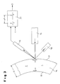
- a rod-shaped specimen 1 can be seen, for measuring the used longitudinal sound velocity c in the material of the sample body becomes.
- d. H the functional relationship about how the Speed of sound c above the temperature T of the material changes.
- the laser-ultrasonic hot-wall thickness measuring method is used which on the classical principle of ultrasonic transit time turns off. From the time for - passing through an ultrasonic pulse through the wall of the - Pipe 14 results in known sound velocity c in the material of the tube the desired wall thickness D.
- the coupling of the ultrasound in the hot wall thickness measurement with temperatures T in the range of about 1,000 ° C requires both on the excitation and the detection side non-contact, optical Methods in which the measuring head itself in a thermally safe distance can remain to the tube 14.
- High-energy light pulses in the infrared range are in the tube surface absorbed. They are of a aligned on the pipe wall, in the embodiment Flash lamp-pumped Nd: YAG laser 15 (excitation laser) - alternative can be a conventional piezoelectric technique (see Fig. 1) or EMUS (Electromagnetic Use ultrasound) technique - which generates a wavelength of 1,064 nm at a pulse duration of less than 10 ns.
- the laser 15 on the pipe surface applied energy absorbed by the pipe wall, partially leads to the evaporation of a very thin surface layer (material ablation in the nm range).
- the reflected ultrasonic pulse is generated on the tube outer surface 17 Vibrations (in the sub-miniature range), which are measured by means of a second laser 18 (detection laser) be detected without contact using the Doppler effect.
- This laser 18 can be a CW laser (continuous wave laser), namely a frequency doubled diode pumped Nd: YAG laser equipped with a Wavelength of 532 nm works and aligned to the point of excitation is.
- the low frequency compared to the light frequency ultrasonic vibration leads to a frequency modulation of the reflected light on the material surface.
- the reflected light cone which is now the "carrier" of the ultrasound signal, is transmitted via a high-intensity positive lens and an optical fiber an optical analyzer 19, d.
- a demodulator fed, in particular a confocal Fabry-Perot interferometer is used; whose output signal includes already the ultrasonic echo sequence.
- the further amplification, filtering and signal evaluation of the ultrasonic echo sequence can with a conventional electronic ultrasound evaluation unit 20 respectively.
- the output signal of the evaluation unit 20 is the wall thickness D of Pipe 14, the product of sound velocity c and measured Time interval .DELTA.t is determined, as indicated schematically in Fig. 3.
- predetermined temperature is - as can be seen in Fig. 1 - proceeded as follows:
- the long specimen 1 in the form of a round rod with 1,000 mm length and 30 mm diameter has at its one end portion 2, two reflection zones. 3 and 4, which consist of notches, which are introduced into the round bar. Both Notches 3, 4 are arranged at a precisely defined distance a, in the embodiment 100 mm. The distance a between the two notches 3, 4 forms the measuring section. The notches 3, 4 are in the embodiment in the area the first 200 mm of the sample body 1 introduced.
- the end portion 2 of the sample body 1 is placed in a furnace 7, where he on the temperature T is heated at which the speed of sound c is measured shall be.
- the remaining, unheated portion of the sample body 1 can be cooled become; shown is a coolant in a water tank 11. It can namely be provided that the unheated portion of the specimen 1, which essentially serves to guide the sound, with one end 6, as shown in FIG. 1, in which water tank 11 is located.
- an ultrasonic source 8 is arranged, wherein it This is preferably a conventional ultrasonic probe 10 in piezo technology is.
- the ultrasonic source 8 leaves a sound wave 5 (compression wave, Longitudinalwelle) in the longitudinal direction L of the sample body 1 in the direction of to run the end section 2.
- the sound wave is reflected ("error echo") and runs - from left to right in Fig. 1 - in the sample body 1 back to the end 6.
- Das reflected sound signal will turn with the conventional ultrasonic probe 10 and determines the duration between the "score echoes".
- a Ultrasonic electronics or evaluation unit 20 receives the measured time interval ⁇ t, which lies between the reflected waves at the two notches 3, 4. By quotient a / ⁇ t the sound velocity c at the temperature T determined.
- the current temperature T is detected by a sensor 21. It is up to a temperature of about 600 ° C in 100 K increments and between 600 ° C to 1200 ° C in 50 K increments.
- the screening of the temperature steps depends on the respective task from.
- the hot tube wall thickness measurement of the T-range above 600 ° C is particularly relevant, you choose in this T-range, in which too Metallurgical transformations take place in the material, the grid is relatively close meshed.
- the course of the speed of sound c is a function of the temperature T before, wherein the thermal expansion of the material is included.
- the end portion 2 of the sample body 1 also be geometrically different.
- the test section by a stepped portion .DELTA.l at the end located in the furnace 7 of the long Sample body (rod) 1 is formed.
- the absorbed by the water tank 11 End 6 of the long specimen 1 are two piezo-ultrasonic probes 10 associated with the ultrasonic electronics or -Ausncetechnik 20 are signaled verbunen.
Abstract
Description
Die Erfindung betrifft ein Verfahren zur Bestimmung der Schallgeschwindigkeit in einem Werkstoff in Abhängigkeit von seiner Temperatur sowie eine Vorrichtung, insbesondere zur Durchführung des Verfahrens.The invention relates to a method for determining the speed of sound in a material as a function of its temperature and a device, in particular for carrying out the method.
In vielen Bereichen der Technik werden Rohre aus Stahl benötigt, die beispielsweise durch ein Verfahren hergestellt werden können, bei dem zylindrisch geformtes Ausgangsmaterial in einem Schrägwalzwerk unter Einsatz eines axial feststehenden Lochdorns zu einem rohrförmigen Hohlblock umgeformt wird. Zur Umformung des zylindrisch geformten Ausgangsmaterials zu einem nahtlosen Rohr wird das Ausgangsmaterial über den Lochdorn gewalzt. Ein solches Verfahren ist beispielsweise aus der EP 0 940 193 A2 bekannt.In many areas of technology pipes made of steel are needed, for example can be produced by a process in which cylindrically shaped Starting material in a cross rolling mill using an axial fixed piercer is formed into a tubular hollow block. to Forming the cylindrically shaped stock into a seamless one Tube, the starting material is rolled over the piercer. Such a procedure is known for example from EP 0 940 193 A2.
Beim Streckreduzierwalzen und beim Reduzier- und Maßwalzen nahtloser Stahlrohre durchläuft das zu bearbeitende Rohr eine Walzstraße, in der in Förderrichtung des Rohres hintereinander eine Anzahl Walzgerüste angeordnet sind. In jedem Walzgerüst sind Walzen gelagert, die beim Walzvorgang das Rohr jeweils um einen definierten Umfangsabschnitt kontaktieren. Insgesamt wirken dabei in jedem Walzgerüst mehrere, beispielsweise drei, Walzen so zusammen, dass das Rohr im wesentlichen über seinen gesamten Umfang von den Walzen kontaktiert wird. Das Rohr wird damit auf einen reduzierten Durchmesser gewalzt und dabei auf eine genaue Form gebracht. For stretch reduction rolling and reduction and sizing of seamless steel tubes the pipe to be processed passes through a rolling train, in the conveying direction the tube in succession a number of rolling stands are arranged. In each Roll stand are stored rolls, which in the rolling process, the pipe in each case Contact a defined peripheral section. Overall, it works in everyone Roll stand several, for example three, rolling together so that the pipe is contacted over substantially the entire circumference of the rollers. The tube is thus rolled to a reduced diameter while on brought a precise shape.
Das Rohr soll nach dem Walzen eine ideale Form haben, d. h. die zylindrische Kontur des Außenumfangs und die des Innenumfangs sollen zwei konzentrische Kreise bilden. Tatsächlich gibt es indes stets Toleranzen im Fertigrohr, so dass eine gewisse Exzentrizität der Kreiskontur des Innenumfangs relativ zu derjenigen des Außenumfangs vorliegt.The tube should have an ideal shape after rolling, d. H. the cylindrical one Contour of the outer circumference and the inner circumference should be two concentric Form circles. In fact, there are always tolerances in the finished pipe, so that a certain eccentricity of the circular contour of the inner circumference relative to that the outer circumference is present.
Der entscheidende Qualitätsparameter bei der Rohrherstellung ist die Rohrwanddicke, die im Produktionsprozess gemessen und überwacht wird. Zur Ermittlung der Wanddicke heißer Rohre sind Laser-Ultraschall-Messverfahren bekannt. Ultraschall-Dicken-Messverfahren nach der Impuls-Echo-Methode ermitteln über die Laufzeitmessung eines Ultraschallimpulses die Wanddicke. Hierfür muss die Schallgeschwindigkeit im Werkstoff bei der vorliegenden Temperatur des Rohres bekannt sein. Die Schallgeschwindigkeit ist sowohl werkstoff- als auch temperaturabhängig. Ein Verfahren zur Messung der Schallgeschwindigkeit in Abhängigkeit von der Temperatur ist aus der DE-PS 12 48 347 bekannt.The decisive quality parameter in pipe production is the pipe wall thickness, which is measured and monitored in the production process. For investigation The wall thickness of hot tubes are known laser ultrasonic measuring method. Ultrasonic thickness measurement method after the pulse echo method determine over the Transit time measurement of an ultrasonic pulse the wall thickness. For this the must Speed of sound in the material at the present temperature of the pipe be known. The speed of sound is both material and temperature dependent. A method of measuring the speed of sound in dependence from the temperature is known from DE-PS 12 48 347.
Aus der CA 2 187 957 A1 ist es bekannt, wie Ultraschallimpulse zur Kontrolle und
Überwachung der Prozessbedingungen in flüssigen Metallen eingesetzt werden
können. Das Prinzip ist auch hier die Impuls-Echo-Methode, die reflektierte Ultraschall-Schwingungen
auswertet.From
Für die Bestimmung der Schallgeschwindigkeit im Material bei einer vorgegebenen Temperatur, die auch bei der bekannten Ausführung die entscheidende Eingangsgröße ist, kommen verschiedene Möglichkeiten in Betracht.For the determination of the speed of sound in the material at a given Temperature, which is also the decisive input in the known design is possible, various options come into consideration.
So kann die benötigte Schallgeschwindigkeit bei einer bestimmten Temperatur durch Interpolation von Werten ermittelt werden, die in einschlägigen Tabellen enthalten sind. Hierbei hat es sich als nachteilhaft herausgestellt, dass der so gewonnene Wert für die Schallgeschwindigkeit zu ungenau ist, um eine hinreichend genaue Bestimmung der Wanddicke zu ermöglichen.So can the required speed of sound at a certain temperature be determined by interpolation of values given in relevant tables are included. It has proved to be disadvantageous that the thus obtained Value for the speed of sound is too inaccurate to a sufficient to allow accurate determination of the wall thickness.
Ein anderer Weg zur Bestimmung der Schallgeschwindigkeit bei einer bestimmten Temperatur sieht vor, dass eine Rohrprobe mit bekannter Wanddicke auf die gewünschte Temperatur erhitzt und mit einem Wanddicken-Messgerät, das nach dem Laser-Ultraschall-Heißwanddicken-Messverfahren (Impuls-Echo-Methode) arbeitet, vermessen wird. Aufgrund der bekannten Wanddicke kann nach Messung des Zeitintervalls zwischen Signal und Echo auf die Schallgeschwindigkeit bei der vorliegenden Temperatur rückgerechnet werden.Another way to determine the speed of sound at a given Temperature provides that a tube sample with known wall thickness to the desired Temperature is heated and with a wall thickness gauge after the laser ultrasonic hot wall thickness measuring method (pulse echo method) works, is measured. Due to the known wall thickness can after measurement the time interval between signal and echo on the speed of sound be recalculated at the present temperature.
Nachteilig ist es hier jedoch, dass bei höheren Temperaturen die Rohrprobe schnell verzundert und so das Messergebnis verfälscht wird. Ferner wird im Messpunkt durch Anwenden des Laer-Ultraschall-Heißwanddicken-Messverfahrens Material abgetragen, so dass die Probe zwischen zwei Messungen bewegt werden muss.The disadvantage here, however, that at higher temperatures, the tube sample quickly scaled and so the measurement result is falsified. Further, in the Measuring point by applying the Laer ultrasonic hot wall thickness measuring method Material removed, leaving the sample between two measurements has to be moved.
Der Erfindung liegt daher die Aufgabe zugrunde, ein Verfahren und eine zugehörige Vorrichtung zu schaffen, mit dem bzw. mit der die vorstehenden Nachteile überwunden werden können. Es soll möglich sein, in einfacher und präziser Weise die longitudinale Schallgeschwindigkeit in einem Werkstoff bei vorgegebener Temperatur bestimmen zu können.The invention is therefore based on the object, a method and an associated To provide device, with or with the above disadvantages can be overcome. It should be possible in a simple and precise manner the longitudinal speed of sound in a material at given Temperature to determine.
Die Lösung dieser Aufgabe sieht verfahrensgemäß die Abfolge der folgenden
Schritte vor:
Dabei wird zumindest das dem erwärmten Endabschnitt gegenüberliegende Ende des Probenkörpers gekühlt.In this case, at least that the heated end portion opposite Cooled end of the specimen.
Um den funktionalen Zusammenhang zwischen Schallgeschwindigkeit und Temperatur zu bestimmen, werden gemäß einer ersten Weiterbildung die obigen Schritte b) bis e) bei unterschiedlichen Temperaturen wiederholt. Dabei erfolgt - wenn die Probe aus Metall, insbesondere aus Stahl, besteht - die Messung der Schallgeschwindigkeit bevorzugt bei Temperaturen zwischen Raumtemperatur und 1.200 °C. Zumeist reicht es dabei aus, wenn die Messung der Schallgeschwindigkeit bei Temperaturen zwischen 600 °C und 1.200 °C in Schritten von 50 K erfolgt. Bei Temperaturen zwischen Raumtemperatur und 600 °C können Schritte von 100 K ausreichen. To the functional relationship between sound velocity and temperature to determine, according to a first development, the above Repeat steps b) to e) at different temperatures. This is done - if the sample consists of metal, in particular of steel, - the measurement of Speed of sound preferred at temperatures between room temperature and 1,200 ° C. In most cases, it is sufficient if the measurement of the speed of sound at temperatures between 600 ° C and 1200 ° C in increments of 50 K takes place. At temperatures between room temperature and 600 ° C can Steps of 100K are sufficient.
Mit Vorteil befinden sich die beiden Reflektionszonen in einem der Endabschnitte des Probenkörpers, wobei im wesentlichen nur dieser Endabschnitt gleichmäßig erwärmt wird. Die Kühlung des dem erwärmten Endabschnitt gegenüberliegenden Ende des Probenkörpers kann vorteilhaft auch für den gesamten nicht erwärmten Teil des Probenkörpers vorgesehen werden.Advantageously, the two reflection zones are located in one of the end sections the sample body, wherein substantially only this end portion uniformly is heated. The cooling of the heated end portion opposite End of the specimen can also be beneficial to the whole unheated Part of the specimen can be provided.
Bevorzugt erfolgt die Einleitung des Ultraschallsignals in den Probenkörper an dem dem erwärmten Endabschnitt gegenüberliegende Ende des Probenkörpers. Die Einleitung des Ultraschallsignals in den Probenkörper kann dabei über ein Piezo-Ultraschallelement mit Wasserankopplung erfolgen.Preferably, the introduction of the ultrasonic signal takes place in the sample body the end of the sample body opposite the heated end portion. The introduction of the ultrasonic signal into the sample body can via a Piezo-ultrasonic element with water coupling done.
Die Vorrichtung zur Bestimmung der Schallgeschwindigkeit weist folgende Elemente auf:
- einen sich in einer Längsrichtung erstreckenden Probenkörper, der aus dem zu vermessenden Werkstoff besteht, wobei der Probenkörper, vorzugsweise in einem seiner Endabschnitte, zwei Reflektionszonen in vorgegebenem Abstand aufweist;
- ein Heizmittel, insbesondere einen Ofen, mit dem zumindest ein Endabschnitt des Probenkörpers auf eine gewünschte Temperatur, bei der die Schallgeschwindigkeit ermittelt werden soll, erwärmt werden kann;
- Mittel zum Einleiten eines Ultraschallsignals in den Probenkörper;
- Mittel zum Messen des Zeitintervalls zwischen zwei Echo-Ultraschallsignalen, die der Probenkörper emittiert, die durch Reflektion des Ultraschallsignals an den beiden Reflektionszonen entstehen;
- Mittel zum Berechnen der Schallgeschwindigkeit als Quotient des Abstands und des Zeitintervalls;
- Mittel zum Kühlen zumindest des dem erwärmten Endabschnitt gegenüberliegenden Endes des Probenkörpers.
- a sample body extending in a longitudinal direction, which consists of the material to be measured, the sample body, preferably in one of its end sections, having two reflection zones at a predetermined distance;
- a heating means, in particular a furnace, with which at least one end portion of the sample body can be heated to a desired temperature at which the speed of sound is to be determined;
- Means for introducing an ultrasonic signal into the sample body;
- Means for measuring the time interval between two echo ultrasonic signals emitted by the sample body resulting from reflection of the ultrasonic signal at the two reflection zones;
- Means for calculating the speed of sound as a quotient of the distance and the time interval;
- Means for cooling at least the end of the sample body opposite the heated end portion.
Der Probenkörper besteht dabei bevorzugt aus einem Rundstab oder einem Flachstab aus dem Probenwerkstoff. Die Reflektionszonen werden mit Vorteil durch Kerben gebildet, die in den Probenkörper eingearbeitet sind. Alternativ dazu ist es aber auch möglich, dass sie durch eine Stufe im Probenkörper und durch das Ende des Probenkörpers gebildet werden; in letzterem Falle ist bevorzugt vorgesehen, dass die Querschnittsveränderung stufenförmig ausgebildet ist.The specimen preferably consists of a round rod or a Flat bar from the sample material. The reflection zones will be beneficial formed by notches, which are incorporated in the sample body. Alternatively But it is also possible that they pass through a stage in the specimen and through the end of the specimen is formed; in the latter case is preferred provided that the cross-sectional change is step-shaped.
Als Mittel zum Einleiten des Ultraschallsignals in den Probenkörper kommt bevorzugt eine herkömmliche Ultraschall-Technik mit Piezo-Prüfköpfen zum Einsatz. Andere Verfahren, wie EMUS (Elektromagnetischer Ultraschall) sind prinzipiell auch denkbar.As a means for introducing the ultrasonic signal into the sample body is preferred a conventional ultrasonic technique with piezo probes used. Other methods, such as EMUS (electromagnetic ultrasound) are in principle also conceivable.
Besonders vorteilhaft ist es, wenn der Probenkörper eine Länge von 750 bis 1.250 mm aufweist, wobei die beiden Reflektionszonen in Form von Kerben im einen Endbereich des Probenkörpers in einem Abstand von 50 bis 200 mm, vorzugsweise in einem Abstand von 100 mm, angeordnet sind. Der Durchmesser des als Rundstab ausgebildeten Probenkörpers liegt bevorzugt zwischen 15 mm und 50 mm, vorzugsweise bei 30 mm.It is particularly advantageous if the specimen has a length of 750 to 1,250 mm, wherein the two reflection zones in the form of notches in one End portion of the sample body at a distance of 50 to 200 mm, preferably at a distance of 100 mm, are arranged. The diameter of the as Round rod trained specimen is preferably between 15 mm and 50 mm, preferably at 30 mm.
Mit der vorgeschlagenen Lösung werden insbesondere folgende Vorteile erreicht:The proposed solution achieves in particular the following advantages:
Die Verzunderung des Materials des Probenkörpers spielt bei dem vorgeschlagenen Verfahren keine Rolle, so dass eine exakte Messung der Schallgeschwindig-keit gewährleistet ist. The scaling of the material of the specimen plays in the proposed Method does not matter, so that an accurate measurement of the sound velocity is guaranteed.
Gleichmaßen ist ein Materialabtrag am Probenkörper durch auftreffendes Laserlicht unbedeutend für die genaue Bestimmung der Schallgeschwindigkeit.Equally, there is a material removal on the specimen by incident laser light insignificant for the exact determination of the speed of sound.
In der Zeichnung sind Ausführungsbeispiele der Erfindung dargestellt. Es zeigen:
- Fig. 1
- schematisch den Aufbau einer Vorrichtung zur Messung der Schallgeschwindigkeit in einem Probenkörper;
- Fig. 2
- den Endabschnitt des Probenkörpers gemäß einer alternativen Ausgestaltung; und
- Fig. 3
- schematisch das Prinzip der Messung der Wanddicke eines heißen Rohres nach den Laser-Ultraschallverfahren, das die ermittelten Schallgeschwindigkeiten verwendet.
- Fig. 1
- schematically the construction of a device for measuring the speed of sound in a sample body;
- Fig. 2
- the end portion of the specimen according to an alternative embodiment; and
- Fig. 3
- schematically the principle of measuring the wall thickness of a hot tube according to the laser ultrasound method, which uses the detected sound velocities.
In Fig. 1 ist ein stabförmiger Probenkörper 1 zu erkennen, der zur Messung der longitudinalen Schallgeschwindigkeit c im Werkstoff des Probenkörpers benutzt wird. Zu ermitteln ist der Verlauf der Schallgeschwindigkeit c über der Temperatur T des Probenkörpers, d. h. der funktionale Zusammenhang darüber, wie sich die Schallgeschwindigkeit c über der Temperatur T des Werkstoffs ändert.In Fig. 1, a rod-shaped specimen 1 can be seen, for measuring the used longitudinal sound velocity c in the material of the sample body becomes. To determine the course of the speed of sound c over the temperature T of the specimen, d. H. the functional relationship about how the Speed of sound c above the temperature T of the material changes.
Ist die Schallgeschwindigkeit c bei vorgegebener Temperatur T bekannt, kann die Wanddicke eines gewalzten Rohres genau gemessen werden, wie es schematisch in Fig. 3 zu sehen ist:If the speed of sound c at a given temperature T known, the Wall thickness of a rolled tube can be measured accurately, as shown schematically can be seen in Fig. 3:
Es kommt das Laser-Ultraschall-Heißwanddickenmessverfahren zum Einsatz, das
auf das klassische Prinzip der Ultraschall-Laufzeitmessung abstellt. Aus der Zeit
für das - zweimalige - Durchlaufen eines Ultraschallimpulses durch die Wand des
Rohres 14 ergibt sich bei bekannter Schallgeschwindigkeit c im Material des Rohres
die gesuchte Wanddicke D. Die Ankopplung des Ultraschalls bei der Heißwanddickenmessung
mit Temperaturen T im Bereich von ca. 1.000 °C erfordert
sowohl auf der Anregungs- als auch auf der Detektionsseite berührungslose, optische
Methoden, bei denen der Messkopf selber in einem thermisch sicheren Abstand
zum Rohr 14 verbleiben kann.The laser-ultrasonic hot-wall thickness measuring method is used which
on the classical principle of ultrasonic transit time turns off. From the time
for - passing through an ultrasonic pulse through the wall of the -
Hochenergetische Licht-Pulse im Infrarotbereich werden in der Rohroberfläche
absorbiert. Sie werden von einem auf die Rohrwand ausgerichteten, im Ausführungsbeispiel
blitzlampen-gepumpten Nd:YAG-Laser 15 (Anregungslaser) - alternativ
läßt sich eine übliche Piezo-Technik (vgl. Fig. 1) oder EMUS (Elektromagnetischer
Ultraschall)-Technik verwenden - erzeugt, der eine Wellenlänge von 1.064
nm bei einer Pulsdauer von weniger als 10 ns haben kann. Die vom Laser 15 auf
die Rohroberfläche aufgebrachte Energie, die von der Rohrwand absorbiert wird,
führt teilweise zur Verdampfung einer sehr dünnen Oberflächenschicht (Materialablation
im nm-Bereich). Durch den Verdampfungs-lmpuls entsteht - wegen der
Impulserhaltung - im Rohr 14 ein Ultraschall-Impuls, der senkrecht zur Rohroberfläche
in die Rohrwand läuft. Der Ultraschall-Impuls wird an der Rohr-Innenoberfläche
16 reflektiert, läuft zurück zur Rohr-Außenoberfläche 17, wird erneut
reflektiert usw., so dass in der Rohrwand eine Ultraschall-Echofolge abnehmender
Amplitude entsteht.High-energy light pulses in the infrared range are in the tube surface
absorbed. They are of a aligned on the pipe wall, in the embodiment
Flash lamp-pumped Nd: YAG laser 15 (excitation laser) - alternative
can be a conventional piezoelectric technique (see Fig. 1) or EMUS (Electromagnetic
Use ultrasound) technique - which generates a wavelength of 1,064
nm at a pulse duration of less than 10 ns. The
Der reflektierte Ultraschallimpuls erzeugt auf der Rohr-Außenoberfläche 17
Schwingungen (im Sub-Miniaturbereich), die mittels eines zweiten Lasers 18 (Erfassungslaser)
berührungslos unter Nutzung des Doppler-Effekts erfasst werden.
Dieser Laser 18 kann ein CW-Laser sein (Continuous Wave Laser), namentlich
ein in der Frequenz verdoppelter, diodengepumpter Nd:YAG-Laser, der mit einer
Wellenlänge von 532 nm arbeitet und auf den Punkt der Anregung ausgerichtet
ist. Die im Vergleich zur Lichtfrequenz niederfrequente Ultraschallschwingung führt
zu einer Frequenz-Modulation des an der Materialoberfläche reflektierten Lichts. The reflected ultrasonic pulse is generated on the tube
Der reflektierte Lichtkegel, der jetzt "Träger" des Ultraschallsignales ist, wird über
eine lichtstarke Sammellinse und einen Lichtwellenleiter einem optischer Analysator
19, d. h. einem Demodulator, zugeführt, wobei insbesondere ein konfokales
Fabry-Perot-Interferometer zum Einsatz kommt; dessen Ausgangssignal beinhaltet
bereits die Ultraschall-Echofolge.The reflected light cone, which is now the "carrier" of the ultrasound signal, is transmitted via
a high-intensity positive lens and an optical fiber an
Die weitere Verstärkung, Filterung und Signalauswertung der Ultraschall-Echofolge
kann mit einer üblichen elektronischen Ultraschall-Auswerteeinheit 20
erfolgen. Das Ausgangssignal der Auswerteeinheit 20 ist die Wanddicke D des
Rohres 14, die aus dem Produkt von Schallgeschwindigkeit c und gemessenem
Zeitintervall Δt bestimmt wird, wie es schematisch in Fig. 3 angedeutet ist.The further amplification, filtering and signal evaluation of the ultrasonic echo sequence
can with a conventional electronic
Zur erfindungsgemäßen Bestimmung der genauen Schallgeschwindigkeit c bei vorbestimmter Temperatur wird - wie in Fig. 1 zu sehen ist - wie folgt vorgegangen:For determining the exact speed of sound c according to the invention predetermined temperature is - as can be seen in Fig. 1 - proceeded as follows:
Der lange Probenkörper 1 in Form eines Rundstabes mit 1.000 mm Länge und 30
mm Durchmesser weist an seinem einen Endabschnitt 2 zwei Reflektionszonen 3
und 4 auf, die aus Kerben bestehen, die in den Rundstab eingebracht sind. Beide
Kerben 3, 4 sind in einem genau bestimmten Abstand a angeordnet, der im Ausführungsbeispiel
100 mm beträgt. Der Abstand a zwischen den beiden Kerben 3, 4
bildet die Messstrecke. Die Kerben 3, 4 sind im Ausführungsbeispiel im Bereich
der ersten 200 mm des Probenkörpers 1 eingebracht.The long specimen 1 in the form of a round rod with 1,000 mm length and 30
mm diameter has at its one
Der Endabschnitt 2 des Probenkörpers 1 ist in einen Ofen 7 eingebracht, wo er auf
die Temperatur T erwärmt wird, bei der die Schallgeschwindigkeit c gemessen
werden soll. Der restliche, nicht geheizte Abschnitt des Probenkörpers 1 kann gekühlt
werden; dargestellt ist ein Kühlmittel in einem Wasserbehälter 11. Es kann
namentlich vorgesehen sein, dass sich der nicht erhitzte Abschnitt des Probenkörpers
1, der im wesentlichen der Schallführung dient, mit einem Ende 6, wie in Fig.
1 dargestellt, in dem Wasserbehälter 11 befindet.The
Am Ende 6 des Probenkörpers 1 ist eine Ultraschallquelle 8 angeordnet, wobei es
sich hier vorzugsweise um einen konventionellen Ultraschall-Prüfkopf 10 in Piezo-Technik
handelt. Die Ultraschallquelle 8 lässt eine Schallwelle 5 (Kompressionswelle,
Longitudinalwelle) in Längsrichtung L des Probenkörpers 1 in Richtung auf
den Endabschnitt 2 zu laufen.At the
An den beiden Kerben 3 und 4 wird die Schallwelle reflektiert ("Fehlerecho") und
läuft - von links nach rechts in Fig. 1 - im Probenkörper 1 zurück zum Ende 6. Das
reflektierte Schallsignal wird wiederum mit dem konventionellen Ultraschall-Prüfkopf
10 erfaßt und die Laufzeit zwischen den "Kerbenechos" ermittelt. Eine
Ultraschall-Elektronik bzw. -Auswerteeinheit 20 erhält das gemessene Zeitintervall
Δt, das zwischen den reflektierten Wellen an den beiden Kerben 3, 4 liegt.
Durch Quotientenbildung a / Δt wird die Schallgeschwindigkeit c bei der Temperatur
T ermittelt.At the two
Wird nach und nach die Temperatur T im Ofen 7 langsam erhöht, kann der funktionale
Zusammenhang c = c (T) gemessen werden. Die jeweils aktuelle Temperatur
T wird von einem Sensor 21 erfasst. Dabei wird bis zu einer Temperatur von
ca. 600 °C in 100 K-Schritten gemessen und zwischen 600 °C bis 1.200 °C in 50
K-Schritten. Die Rasterung der Temperaturschritte hängt von der jeweiligen Aufgabenstellung
ab. Da für die Heißrohr-Wanddickenmessung der T-Bereich oberhalb
600°C besonders relevant ist, wählt man in diesem T-Bereich, in dem auch
metallurgische Umwandlungen im Material erfolgen, das Raster relativ engmaschig. As the temperature T in the
Als Ergebnis liegt der Verlauf der Schallgeschwindigkeit c als Funktion der Temperatur T vor, wobei die Wärmeausdehnung des Materials mit enthalten ist.As a result, the course of the speed of sound c is a function of the temperature T before, wherein the thermal expansion of the material is included.
Wie in Fig. 2 zu sehen ist, kann der Endabschnitt 2 des Probenkörpers 1 auch
geometrisch anders ausgeführt sein. Hier ist vorgesehen, dass die Meßstrecke
durch einen gestuften Abschnitt Δl an dem im Ofen 7 befindlichen Ende des langen
Probenkörpers (Stab) 1 gebildet wird. Dem vom Wasserbehälter 11 aufgenommenen
Ende 6 des langen Probenkörpers 1 sind zwei Piezo-Ultraschall-Prüfköpfe
10 zugeordnet, die mit der Ultraschall-Elektronik bzw. -Auswerteeinheit
20 signaltechnisch verbunen sind.As can be seen in Fig. 2, the
Unter der Annahme, dass der Probenkörper 1 während des Aufheizens in seinem
Endabschnitt 2 nicht ungleichmäßig verzundert, liefert die Laufzeitdifferenz der
reflektierten Wellen die gewünschte Information, um die Schallgeschwindigkeit c
bestimmen zu können. Assuming that the specimen 1 during heating in his
- 11
- Probenkörperspecimen
- 22
- Endabschnitt des ProbenkörpersEnd portion of the specimen
- 33
- Reflektionszonereflection zone
- 44
- Reflektionszonereflection zone
- 55
- Ultraschallsignalultrasonic signal
- 66
- Ende des ProbenkörpersEnd of the specimen
- 77
- Heizmittel (Ofen)Heating means (oven)
- 88th
- Ultraschallquelleultrasound source
- 1010
- Piezo-Ultraschall-PrüfkopfPiezoelectric ultrasonic probe
- 1111
- Wasserbehälterwater tank
- 1414
- Rohrpipe
- 1515
- Anregungslaserexcitation laser
- 1616
- Rohr-InnenoberflächePipe inner surface
- 1717
- Rohr-AußenoberflächeTube outer surface
- 1818
- Erfassungslaserregistration laser
- 1919
- optischer Analysator (Fabry-Perot-Interferometer)optical analyzer (Fabry-Perot interferometer)
- 2020
- Ultraschall-AuswerteeinheitUltrasound evaluation
- 2121
- Temperatursensortemperature sensor
- cc
- Schallgeschwindigkeitspeed of sound
- TT
- Temperaturtemperature
- LL
- Längsrichtunglongitudinal direction
- aa
- Abstanddistance
- tt
- Zeitintervalltime interval
- DD
- Wanddickewall thickness
- Δl.DELTA.l
- gestufter Abschnittstepped section
Claims (15)
dadurch gekennzeichnet, dass die Schritte b) bis e) bei unterschiedlichen Temperaturen (T) wiederholt werden.Method according to claim 1,
characterized in that the steps b) to e) are repeated at different temperatures (T).
dadurch gekennzeichnet, dass das Probenmaterial Metall, insbesondere Stahl, ist und die Messung der Schallgeschwindigkeit (c) bei Temperaturen (T) zwischen Raumtemperatur und 1.200 °C erfolgt.Method according to claim 2,
characterized in that the sample material is metal, in particular steel, and the measurement of the speed of sound (c) takes place at temperatures (T) between room temperature and 1200 ° C.
dadurch gekennzeichnet, dass die Messung der Schallgeschwindigkeit (c) bei Temperaturen (T) zwischen 600 °C und 1.200 °C in Schritten von 50 K erfolgt.Method according to claim 3,
characterized in that the measurement of the speed of sound (c) at temperatures (T) between 600 ° C and 1200 ° C in steps of 50 K takes place.
dadurch gekennzeichnet, dass die Messung der Schallgeschwindigkeit (c) bei Temperaturen (T) zwischen Raumtemperatur und 600 °C in Schritten von 100 K erfolgt.Method according to claim 3,
characterized in that the measurement of the speed of sound (c) takes place at temperatures (T) between room temperature and 600 ° C in steps of 100 K.
dadurch gekennzeichnet, dass der gesamte nicht erwärmte Teil des Probenkörpers (1) gekühlt wird.Method according to one of claims 1 to 5,
characterized in that the entire unheated part of the sample body (1) is cooled.
dadurch gekennzeichnet, dass das Ultraschallsignal (5) in den Probenkörper (1) an dem dem erwärmten Endabschnitt (2) gegenüberliegende Ende (6) des Probenkörpers (1) eingeleitet wird. Method according to one of claims 1 to 6,
characterized in that the ultrasonic signal (5) is introduced into the sample body (1) at the end (6) of the sample body (1) opposite the heated end portion (2).
dadurch gekennzeichnet, dass das Ultraschallsignal (5) in den Probenkörper (1) über ein Piezo-Ultraschallelement mit Wasserankopplung eingeleitet wird.Method according to one of claims 1 to 7,
characterized in that the ultrasonic signal (5) is introduced into the sample body (1) via a piezo-ultrasonic element with water coupling.
gekennzeichnet durch
marked by
dadurch gekennzeichnet, dass der Probenkörper (1) als ein Rundstab oder Flachstab aus dem Probenwerkstoff ausgebildet ist.Device according to claim 9,
characterized in that the sample body (1) is designed as a round bar or flat bar of the sample material.
dadurch gekennzeichnet, dass die Reflektionszonen (3, 4) als in den Probenkörper (1) eingearbeitete Kerben ausgebildet sind.Device according to claim 9 or 10,
characterized in that the reflection zones (3, 4) are formed as in the sample body (1) incorporated notches.
dadurch gekennzeichnet, dass die Reflektionszonen (3, 4) durch eine Querschnittsveränderung im Probenkörper (1) ausgebildet sind.Device according to claim 9 or 10,
characterized in that the reflection zones (3, 4) are formed by a cross-sectional change in the sample body (1).
dadurch gekennzeichnet, dass die Querschnittsveränderung stufenförmig ausgebildet ist.Device according to claim 12,
characterized in that the cross-sectional change is step-shaped.
dadurch gekennzeichnet, dass der Probenkörper (1) eine Länge von 750 bis 1.250 mm aufweist, wobei die beiden Reflektionszonen (3, 4) in Form von Kerben im einen Endbereich (2) des Probenkörpers (1) in einem Abstand von 50 bis 200 mm, vorzugsweise in einem Abstand von 100 mm, angeordnet sind. Device according to one of claims 9 to 13,
characterized in that the sample body (1) has a length of 750 to 1250 mm, wherein the two reflection zones (3, 4) in the form of notches in one end region (2) of the sample body (1) at a distance of 50 to 200 mm , preferably at a distance of 100 mm, are arranged.
dadurch gekennzeichnet, dass der Probenkörper (1) als Rundstab mit einem Durchmesser zwischen 15 mm und 50 mm, vorzugsweise mit einem Durchmesser von 30 mm, ausgebildet ist.Device according to claim 14,
characterized in that the sample body (1) as a round rod with a diameter between 15 mm and 50 mm, preferably with a diameter of 30 mm, is formed.
Applications Claiming Priority (2)
| Application Number | Priority Date | Filing Date | Title |
|---|---|---|---|
| DE10223786 | 2002-05-29 | ||
| DE10223786A DE10223786C1 (en) | 2002-05-29 | 2002-05-29 | Determining sound velocity in steel as a function of temperature for wall thickness determination, measures interval between signals reflected at locations within heating zone |
Publications (2)
| Publication Number | Publication Date |
|---|---|
| EP1367390A1 true EP1367390A1 (en) | 2003-12-03 |
| EP1367390B1 EP1367390B1 (en) | 2007-09-19 |
Family
ID=7714588
Family Applications (1)
| Application Number | Title | Priority Date | Filing Date |
|---|---|---|---|
| EP03010646A Expired - Lifetime EP1367390B1 (en) | 2002-05-29 | 2003-05-13 | Method and apparatus for determination of sound velocity of a material depending on the temperature |
Country Status (6)
| Country | Link |
|---|---|
| US (1) | US6810742B2 (en) |
| EP (1) | EP1367390B1 (en) |
| AT (1) | ATE373821T1 (en) |
| CA (1) | CA2428384C (en) |
| DE (2) | DE10223786C1 (en) |
| ES (1) | ES2290380T3 (en) |
Families Citing this family (7)
| Publication number | Priority date | Publication date | Assignee | Title |
|---|---|---|---|---|
| US7614302B2 (en) | 2005-08-01 | 2009-11-10 | Baker Hughes Incorporated | Acoustic fluid analysis method |
| JP4826949B2 (en) † | 2006-09-11 | 2011-11-30 | 住友金属工業株式会社 | Seamless pipe manufacturing status monitoring apparatus and method, and seamless pipe manufacturing equipment |
| US7933027B1 (en) * | 2008-06-27 | 2011-04-26 | The United States Of America As Represented By The Administrator Of National Aeronautics And Space Administration | Processing waveform-based NDE |
| US7876423B1 (en) * | 2008-06-27 | 2011-01-25 | The United States Of America As Represented By The National Aeronautics And Space Administration | Simultaneous noncontact precision imaging of microstructural and thickness variation in dielectric materials using terahertz energy |
| RU2613485C2 (en) * | 2015-06-29 | 2017-03-16 | Федеральное государственное бюджетное учреждение науки Институт радиотехники и электроники им. В.А. Котельникова Российской академии наук | Method for measuring sound velocity vertical distribution in water |
| CN106546662B (en) * | 2016-10-31 | 2019-11-08 | 中国科学院地质与地球物理研究所 | Rocks acoustic velocity test method under the conditions of a kind of full cement rock High Pressure Drain |
| CN114384155A (en) * | 2022-01-12 | 2022-04-22 | 重庆医科大学 | Measuring system and method for measuring sound velocity of medium in waveguide |
Citations (2)
| Publication number | Priority date | Publication date | Assignee | Title |
|---|---|---|---|---|
| DE1248347B (en) * | 1962-02-07 | 1967-08-24 | Euratom | Method for measuring the speed of sound in a body |
| US4762425A (en) * | 1987-10-15 | 1988-08-09 | Parthasarathy Shakkottai | System for temperature profile measurement in large furnances and kilns and method therefor |
Family Cites Families (12)
| Publication number | Priority date | Publication date | Assignee | Title |
|---|---|---|---|---|
| US3943755A (en) * | 1974-10-22 | 1976-03-16 | Tokyo Shibaura Electric Co., Ltd. | Method and apparatus for measuring the magnitude of a clamping load applied to a laminated iron core of an electric machine |
| US4246793A (en) * | 1979-02-08 | 1981-01-27 | Battelle Development Corporation | Nondestructive testing |
| GB2114297A (en) * | 1982-02-10 | 1983-08-17 | Euratom | Very high temperature ultrasonic thermometer |
| US4567770A (en) * | 1983-03-21 | 1986-02-04 | Sonic Instruments Inc. | Ultrasonic transducer apparatus and method for high temperature measurements |
| US5648611A (en) * | 1993-12-22 | 1997-07-15 | The Timken Company | Process for measuring the case depth of case-carburized steel |
| US5379270A (en) * | 1994-03-25 | 1995-01-03 | The United States Of America As Represented By The Secretary Of The Navy | Acoustic-optic sound velocity profiler |
| US6175416B1 (en) * | 1996-08-06 | 2001-01-16 | Brown University Research Foundation | Optical stress generator and detector |
| US5684252A (en) * | 1996-07-15 | 1997-11-04 | Sonoscan, Inc. | Method and apparatus for ultrasonic inspection of electronic components |
| CA2187957C (en) | 1996-10-16 | 2003-06-03 | Cheng-Kuei Jen | Ultrasonic sensors for on-line monitoring of castings and molding processes at elevated temperatures |
| IT1298331B1 (en) | 1998-03-04 | 1999-12-20 | Mannesmann Ag | PROCEDURE FOR THE PRODUCTION OF PIPES WITHOUT WELDING |
| US6069703A (en) * | 1998-05-28 | 2000-05-30 | Active Impulse Systems, Inc. | Method and device for simultaneously measuring the thickness of multiple thin metal films in a multilayer structure |
| US6628404B1 (en) * | 2000-11-21 | 2003-09-30 | Sandia Corporation | Acoustic sensor for real-time control for the inductive heating process |
-
2002
- 2002-05-29 DE DE10223786A patent/DE10223786C1/en not_active Expired - Fee Related
-
2003
- 2003-05-08 CA CA002428384A patent/CA2428384C/en not_active Expired - Fee Related
- 2003-05-13 EP EP03010646A patent/EP1367390B1/en not_active Expired - Lifetime
- 2003-05-13 AT AT03010646T patent/ATE373821T1/en not_active IP Right Cessation
- 2003-05-13 ES ES03010646T patent/ES2290380T3/en not_active Expired - Lifetime
- 2003-05-13 DE DE50308207T patent/DE50308207D1/en not_active Expired - Lifetime
- 2003-05-28 US US10/446,503 patent/US6810742B2/en not_active Expired - Lifetime
Patent Citations (2)
| Publication number | Priority date | Publication date | Assignee | Title |
|---|---|---|---|---|
| DE1248347B (en) * | 1962-02-07 | 1967-08-24 | Euratom | Method for measuring the speed of sound in a body |
| US4762425A (en) * | 1987-10-15 | 1988-08-09 | Parthasarathy Shakkottai | System for temperature profile measurement in large furnances and kilns and method therefor |
Non-Patent Citations (1)
| Title |
|---|
| HE P: "Simultaneous measurement of sound velocity and wall thickness of a tube", ULTRASONICS, IPC SCIENCE AND TECHNOLOGY PRESS LTD. GUILDFORD, GB, vol. 39, no. 6, October 2001 (2001-10-01), pages 407 - 411, XP004324322, ISSN: 0041-624X * |
Also Published As
| Publication number | Publication date |
|---|---|
| ATE373821T1 (en) | 2007-10-15 |
| DE10223786C1 (en) | 2003-07-10 |
| US6810742B2 (en) | 2004-11-02 |
| CA2428384A1 (en) | 2003-11-29 |
| CA2428384C (en) | 2006-09-05 |
| DE50308207D1 (en) | 2007-10-31 |
| ES2290380T3 (en) | 2008-02-16 |
| US20030221490A1 (en) | 2003-12-04 |
| EP1367390B1 (en) | 2007-09-19 |
Similar Documents
| Publication | Publication Date | Title |
|---|---|---|
| DE60132389T2 (en) | Production process for a continuously cast steel product | |
| EP0653061B1 (en) | Process for assessing welded joints | |
| DE10084306B4 (en) | Ultrasonic detection device and an ultrasonic detection method using this | |
| EP1369664B1 (en) | Method and device for measuring the excentricity of a hollow block | |
| DE102008027228B4 (en) | Method and device for the non-destructive ultrasound examination of a test piece with mutually angled, flat surfaces | |
| EP1491887B1 (en) | Method for ultrasonic determination of the porosity of a workpiece | |
| EP0160922B1 (en) | Method for the ultrasonic non-destructive testing of objects and components, and apparatus for using the same | |
| EP1367390B1 (en) | Method and apparatus for determination of sound velocity of a material depending on the temperature | |
| EP1850979B1 (en) | Method and device for monitoring the production process of hot-finished steel pipes | |
| EP1134579A2 (en) | Method and apparatus for photothermically analysing a material layer, especially film thickness measurement | |
| EP1890140A1 (en) | Method for checking the joint structure of a welded joint | |
| EP1391687B1 (en) | Apparatus for mapping the wall thickness of a tube in a mandrel mill | |
| DE19640859B4 (en) | Method and device for non-destructive determination of the material condition in components | |
| EP1378299A1 (en) | Method and apparatus for determining the eccentricity of a hollow block | |
| DE102011115691B4 (en) | Method for determining the viscosity of a flowing or static fluid | |
| EP3469350B1 (en) | Method, device and use for the device for quantitively determining the concentration or particle size of a component of a heterogeneous material mixture | |
| DE4305064C1 (en) | Non-destructive testing system, e.g. for turbine blade - uses laser beams to stimulate ultrasonic surface waves at spaced points for simultaneous measurement of different characteristics | |
| DE102006028369B4 (en) | Method and device for process control in the rolling of metals | |
| EP2623952A1 (en) | Method and device for detecting surface cracks | |
| WO2009049589A1 (en) | Method and apparatus for measuring the eccentricity of a hot-fabricated seamless tube during production | |
| DE2939480A1 (en) | METHOD FOR DETERMINING Cracks AND THE LIKE IN A TUBE USING ULTRASOUND | |
| DD293285A5 (en) | METHOD AND DEVICE FOR CONTINUOUS CASTING OF DUENNE METALLIC OBJECTS | |
| DE4239159C2 (en) | Device for the non-destructive measurement of the thickness of a hardness layer | |
| DE10102628A1 (en) | Measuring bore in workpiece formed by honing tool by geometrically evaluating wall thickness signal e.g. from ultrasound sensor | |
| DE19915203C2 (en) | Method and device for the non-destructive testing of steel that is to be rolled and is still easily deformable for internal defects |
Legal Events
| Date | Code | Title | Description |
|---|---|---|---|
| PUAI | Public reference made under article 153(3) epc to a published international application that has entered the european phase |
Free format text: ORIGINAL CODE: 0009012 |
|
| AK | Designated contracting states |
Kind code of ref document: A1 Designated state(s): AT BE BG CH CY CZ DE DK EE ES FI FR GB GR HU IE IT LI LU MC NL PT RO SE SI SK TR |
|
| AX | Request for extension of the european patent |
Extension state: AL LT LV MK |
|
| RIN1 | Information on inventor provided before grant (corrected) |
Inventor name: DEPPE, GERD-JOACHIM DR. Inventor name: SAUERLAND, MARTIN |
|
| 17P | Request for examination filed |
Effective date: 20040525 |
|
| AKX | Designation fees paid |
Designated state(s): AT BE BG CH CY CZ DE DK EE ES FI FR GB GR HU IE IT LI LU MC NL PT RO SE SI SK TR |
|
| GRAP | Despatch of communication of intention to grant a patent |
Free format text: ORIGINAL CODE: EPIDOSNIGR1 |
|
| RIC1 | Information provided on ipc code assigned before grant |
Ipc: G01N 29/07 20060101AFI20070309BHEP Ipc: G01H 5/00 20060101ALI20070309BHEP |
|
| R17C | First examination report despatched (corrected) |
Effective date: 20070321 |
|
| GRAS | Grant fee paid |
Free format text: ORIGINAL CODE: EPIDOSNIGR3 |
|
| GRAA | (expected) grant |
Free format text: ORIGINAL CODE: 0009210 |
|
| AK | Designated contracting states |
Kind code of ref document: B1 Designated state(s): AT BE BG CH CY CZ DE DK EE ES FI FR GB GR HU IE IT LI LU MC NL PT RO SE SI SK TR |
|
| REG | Reference to a national code |
Ref country code: GB Ref legal event code: FG4D Free format text: NOT ENGLISH |
|
| REG | Reference to a national code |
Ref country code: CH Ref legal event code: EP |
|
| REF | Corresponds to: |
Ref document number: 50308207 Country of ref document: DE Date of ref document: 20071031 Kind code of ref document: P |
|
| REG | Reference to a national code |
Ref country code: SE Ref legal event code: TRGR |
|
| REG | Reference to a national code |
Ref country code: IE Ref legal event code: FG4D Free format text: LANGUAGE OF EP DOCUMENT: GERMAN |
|
| PG25 | Lapsed in a contracting state [announced via postgrant information from national office to epo] |
Ref country code: FI Free format text: LAPSE BECAUSE OF FAILURE TO SUBMIT A TRANSLATION OF THE DESCRIPTION OR TO PAY THE FEE WITHIN THE PRESCRIBED TIME-LIMIT Effective date: 20070919 |
|
| REG | Reference to a national code |
Ref country code: ES Ref legal event code: FG2A Ref document number: 2290380 Country of ref document: ES Kind code of ref document: T3 |
|
| NLV1 | Nl: lapsed or annulled due to failure to fulfill the requirements of art. 29p and 29m of the patents act | ||
| ET | Fr: translation filed | ||
| PG25 | Lapsed in a contracting state [announced via postgrant information from national office to epo] |
Ref country code: NL Free format text: LAPSE BECAUSE OF FAILURE TO SUBMIT A TRANSLATION OF THE DESCRIPTION OR TO PAY THE FEE WITHIN THE PRESCRIBED TIME-LIMIT Effective date: 20070919 Ref country code: GR Free format text: LAPSE BECAUSE OF FAILURE TO SUBMIT A TRANSLATION OF THE DESCRIPTION OR TO PAY THE FEE WITHIN THE PRESCRIBED TIME-LIMIT Effective date: 20071220 |
|
| REG | Reference to a national code |
Ref country code: IE Ref legal event code: FD4D |
|
| PG25 | Lapsed in a contracting state [announced via postgrant information from national office to epo] |
Ref country code: PT Free format text: LAPSE BECAUSE OF FAILURE TO SUBMIT A TRANSLATION OF THE DESCRIPTION OR TO PAY THE FEE WITHIN THE PRESCRIBED TIME-LIMIT Effective date: 20080219 Ref country code: GB Free format text: LAPSE BECAUSE OF FAILURE TO SUBMIT A TRANSLATION OF THE DESCRIPTION OR TO PAY THE FEE WITHIN THE PRESCRIBED TIME-LIMIT Effective date: 20070919 |
|
| PG25 | Lapsed in a contracting state [announced via postgrant information from national office to epo] |
Ref country code: RO Free format text: LAPSE BECAUSE OF FAILURE TO SUBMIT A TRANSLATION OF THE DESCRIPTION OR TO PAY THE FEE WITHIN THE PRESCRIBED TIME-LIMIT Effective date: 20070919 |
|
| PLBE | No opposition filed within time limit |
Free format text: ORIGINAL CODE: 0009261 |
|
| STAA | Information on the status of an ep patent application or granted ep patent |
Free format text: STATUS: NO OPPOSITION FILED WITHIN TIME LIMIT |
|
| PG25 | Lapsed in a contracting state [announced via postgrant information from national office to epo] |
Ref country code: DK Free format text: LAPSE BECAUSE OF FAILURE TO SUBMIT A TRANSLATION OF THE DESCRIPTION OR TO PAY THE FEE WITHIN THE PRESCRIBED TIME-LIMIT Effective date: 20070919 |
|
| 26N | No opposition filed |
Effective date: 20080620 |
|
| PG25 | Lapsed in a contracting state [announced via postgrant information from national office to epo] |
Ref country code: IE Free format text: LAPSE BECAUSE OF FAILURE TO SUBMIT A TRANSLATION OF THE DESCRIPTION OR TO PAY THE FEE WITHIN THE PRESCRIBED TIME-LIMIT Effective date: 20070919 |
|
| BERE | Be: lapsed |
Owner name: SMS MEER G.M.B.H. Effective date: 20080531 |
|
| PG25 | Lapsed in a contracting state [announced via postgrant information from national office to epo] |
Ref country code: MC Free format text: LAPSE BECAUSE OF NON-PAYMENT OF DUE FEES Effective date: 20080531 |
|
| REG | Reference to a national code |
Ref country code: CH Ref legal event code: PL |
|
| PG25 | Lapsed in a contracting state [announced via postgrant information from national office to epo] |
Ref country code: LI Free format text: LAPSE BECAUSE OF NON-PAYMENT OF DUE FEES Effective date: 20080531 Ref country code: EE Free format text: LAPSE BECAUSE OF FAILURE TO SUBMIT A TRANSLATION OF THE DESCRIPTION OR TO PAY THE FEE WITHIN THE PRESCRIBED TIME-LIMIT Effective date: 20070919 Ref country code: CH Free format text: LAPSE BECAUSE OF NON-PAYMENT OF DUE FEES Effective date: 20080531 |
|
| PG25 | Lapsed in a contracting state [announced via postgrant information from national office to epo] |
Ref country code: BE Free format text: LAPSE BECAUSE OF NON-PAYMENT OF DUE FEES Effective date: 20080531 |
|
| PG25 | Lapsed in a contracting state [announced via postgrant information from national office to epo] |
Ref country code: SI Free format text: LAPSE BECAUSE OF FAILURE TO SUBMIT A TRANSLATION OF THE DESCRIPTION OR TO PAY THE FEE WITHIN THE PRESCRIBED TIME-LIMIT Effective date: 20070919 |
|
| PG25 | Lapsed in a contracting state [announced via postgrant information from national office to epo] |
Ref country code: CY Free format text: LAPSE BECAUSE OF FAILURE TO SUBMIT A TRANSLATION OF THE DESCRIPTION OR TO PAY THE FEE WITHIN THE PRESCRIBED TIME-LIMIT Effective date: 20070919 |
|
| PG25 | Lapsed in a contracting state [announced via postgrant information from national office to epo] |
Ref country code: AT Free format text: LAPSE BECAUSE OF NON-PAYMENT OF DUE FEES Effective date: 20080513 Ref country code: BG Free format text: LAPSE BECAUSE OF FAILURE TO SUBMIT A TRANSLATION OF THE DESCRIPTION OR TO PAY THE FEE WITHIN THE PRESCRIBED TIME-LIMIT Effective date: 20071219 |
|
| PG25 | Lapsed in a contracting state [announced via postgrant information from national office to epo] |
Ref country code: HU Free format text: LAPSE BECAUSE OF FAILURE TO SUBMIT A TRANSLATION OF THE DESCRIPTION OR TO PAY THE FEE WITHIN THE PRESCRIBED TIME-LIMIT Effective date: 20080320 Ref country code: LU Free format text: LAPSE BECAUSE OF NON-PAYMENT OF DUE FEES Effective date: 20080513 |
|
| PG25 | Lapsed in a contracting state [announced via postgrant information from national office to epo] |
Ref country code: TR Free format text: LAPSE BECAUSE OF FAILURE TO SUBMIT A TRANSLATION OF THE DESCRIPTION OR TO PAY THE FEE WITHIN THE PRESCRIBED TIME-LIMIT Effective date: 20070919 |
|
| REG | Reference to a national code |
Ref country code: DE Ref legal event code: R082 Ref document number: 50308207 Country of ref document: DE Representative=s name: HEMMERICH & KOLLEGEN, DE Ref country code: DE Ref legal event code: R081 Ref document number: 50308207 Country of ref document: DE Owner name: SMS GROUP GMBH, DE Free format text: FORMER OWNER: SMS MEER GMBH, 41069 MOENCHENGLADBACH, DE |
|
| REG | Reference to a national code |
Ref country code: FR Ref legal event code: PLFP Year of fee payment: 14 |
|
| REG | Reference to a national code |
Ref country code: FR Ref legal event code: PLFP Year of fee payment: 15 |
|
| PGFP | Annual fee paid to national office [announced via postgrant information from national office to epo] |
Ref country code: FR Payment date: 20170523 Year of fee payment: 15 Ref country code: DE Payment date: 20170523 Year of fee payment: 15 |
|
| PGFP | Annual fee paid to national office [announced via postgrant information from national office to epo] |
Ref country code: IT Payment date: 20170526 Year of fee payment: 15 Ref country code: ES Payment date: 20170627 Year of fee payment: 15 Ref country code: SE Payment date: 20170519 Year of fee payment: 15 |
|
| PGFP | Annual fee paid to national office [announced via postgrant information from national office to epo] |
Ref country code: CZ Payment date: 20180510 Year of fee payment: 16 Ref country code: SK Payment date: 20180510 Year of fee payment: 16 |
|
| REG | Reference to a national code |
Ref country code: DE Ref legal event code: R119 Ref document number: 50308207 Country of ref document: DE |
|
| REG | Reference to a national code |
Ref country code: SE Ref legal event code: EUG |
|
| PG25 | Lapsed in a contracting state [announced via postgrant information from national office to epo] |
Ref country code: SE Free format text: LAPSE BECAUSE OF NON-PAYMENT OF DUE FEES Effective date: 20180514 |
|
| PG25 | Lapsed in a contracting state [announced via postgrant information from national office to epo] |
Ref country code: FR Free format text: LAPSE BECAUSE OF NON-PAYMENT OF DUE FEES Effective date: 20180531 Ref country code: IT Free format text: LAPSE BECAUSE OF NON-PAYMENT OF DUE FEES Effective date: 20180513 Ref country code: DE Free format text: LAPSE BECAUSE OF NON-PAYMENT OF DUE FEES Effective date: 20181201 |
|
| REG | Reference to a national code |
Ref country code: ES Ref legal event code: FD2A Effective date: 20190913 |
|
| PG25 | Lapsed in a contracting state [announced via postgrant information from national office to epo] |
Ref country code: ES Free format text: LAPSE BECAUSE OF NON-PAYMENT OF DUE FEES Effective date: 20180514 |
|
| PG25 | Lapsed in a contracting state [announced via postgrant information from national office to epo] |
Ref country code: CZ Free format text: LAPSE BECAUSE OF NON-PAYMENT OF DUE FEES Effective date: 20190513 Ref country code: SK Free format text: LAPSE BECAUSE OF NON-PAYMENT OF DUE FEES Effective date: 20190513 |
|
| REG | Reference to a national code |
Ref country code: SK Ref legal event code: MM4A Ref document number: E 2772 Country of ref document: SK Effective date: 20190513 |