EP1366908A1 - Ink tank for feeding a shuttling inkjet printing head - Google Patents
Ink tank for feeding a shuttling inkjet printing head Download PDFInfo
- Publication number
- EP1366908A1 EP1366908A1 EP02100552A EP02100552A EP1366908A1 EP 1366908 A1 EP1366908 A1 EP 1366908A1 EP 02100552 A EP02100552 A EP 02100552A EP 02100552 A EP02100552 A EP 02100552A EP 1366908 A1 EP1366908 A1 EP 1366908A1
- Authority
- EP
- European Patent Office
- Prior art keywords
- ink
- ink tank
- tank
- print head
- shuttling
- Prior art date
- Legal status (The legal status is an assumption and is not a legal conclusion. Google has not performed a legal analysis and makes no representation as to the accuracy of the status listed.)
- Withdrawn
Links
- 238000007641 inkjet printing Methods 0.000 title description 5
- 235000014676 Phragmites communis Nutrition 0.000 claims description 5
- 230000009977 dual effect Effects 0.000 claims description 4
- 238000007872 degassing Methods 0.000 claims description 2
- 239000000976 ink Substances 0.000 description 156
- 230000001133 acceleration Effects 0.000 description 8
- 238000007639 printing Methods 0.000 description 8
- 230000002706 hydrostatic effect Effects 0.000 description 5
- 230000005484 gravity Effects 0.000 description 4
- 230000005499 meniscus Effects 0.000 description 3
- 238000000034 method Methods 0.000 description 3
- 238000005192 partition Methods 0.000 description 3
- 238000000605 extraction Methods 0.000 description 2
- 230000000712 assembly Effects 0.000 description 1
- 238000000429 assembly Methods 0.000 description 1
- 239000011248 coating agent Substances 0.000 description 1
- 238000000576 coating method Methods 0.000 description 1
- 239000003086 colorant Substances 0.000 description 1
- 238000013016 damping Methods 0.000 description 1
- 230000007547 defect Effects 0.000 description 1
- 230000001419 dependent effect Effects 0.000 description 1
- 238000001514 detection method Methods 0.000 description 1
- 230000000694 effects Effects 0.000 description 1
- 238000005516 engineering process Methods 0.000 description 1
- 238000001746 injection moulding Methods 0.000 description 1
- 238000004519 manufacturing process Methods 0.000 description 1
- 238000005259 measurement Methods 0.000 description 1
- 230000007246 mechanism Effects 0.000 description 1
- 238000012986 modification Methods 0.000 description 1
- 230000004048 modification Effects 0.000 description 1
- 230000007935 neutral effect Effects 0.000 description 1
- 238000007645 offset printing Methods 0.000 description 1
- 238000005086 pumping Methods 0.000 description 1
- 230000001105 regulatory effect Effects 0.000 description 1
- 230000002459 sustained effect Effects 0.000 description 1
Images

Classifications
-
- B—PERFORMING OPERATIONS; TRANSPORTING
- B41—PRINTING; LINING MACHINES; TYPEWRITERS; STAMPS
- B41J—TYPEWRITERS; SELECTIVE PRINTING MECHANISMS, i.e. MECHANISMS PRINTING OTHERWISE THAN FROM A FORME; CORRECTION OF TYPOGRAPHICAL ERRORS
- B41J2/00—Typewriters or selective printing mechanisms characterised by the printing or marking process for which they are designed
- B41J2/005—Typewriters or selective printing mechanisms characterised by the printing or marking process for which they are designed characterised by bringing liquid or particles selectively into contact with a printing material
- B41J2/01—Ink jet
- B41J2/17—Ink jet characterised by ink handling
- B41J2/175—Ink supply systems ; Circuit parts therefor
- B41J2/17503—Ink cartridges
- B41J2/17556—Means for regulating the pressure in the cartridge
-
- B—PERFORMING OPERATIONS; TRANSPORTING
- B41—PRINTING; LINING MACHINES; TYPEWRITERS; STAMPS
- B41J—TYPEWRITERS; SELECTIVE PRINTING MECHANISMS, i.e. MECHANISMS PRINTING OTHERWISE THAN FROM A FORME; CORRECTION OF TYPOGRAPHICAL ERRORS
- B41J2/00—Typewriters or selective printing mechanisms characterised by the printing or marking process for which they are designed
- B41J2/005—Typewriters or selective printing mechanisms characterised by the printing or marking process for which they are designed characterised by bringing liquid or particles selectively into contact with a printing material
- B41J2/01—Ink jet
- B41J2/17—Ink jet characterised by ink handling
- B41J2/175—Ink supply systems ; Circuit parts therefor
- B41J2/17503—Ink cartridges
- B41J2/17513—Inner structure
-
- B—PERFORMING OPERATIONS; TRANSPORTING
- B41—PRINTING; LINING MACHINES; TYPEWRITERS; STAMPS
- B41J—TYPEWRITERS; SELECTIVE PRINTING MECHANISMS, i.e. MECHANISMS PRINTING OTHERWISE THAN FROM A FORME; CORRECTION OF TYPOGRAPHICAL ERRORS
- B41J2/00—Typewriters or selective printing mechanisms characterised by the printing or marking process for which they are designed
- B41J2/005—Typewriters or selective printing mechanisms characterised by the printing or marking process for which they are designed characterised by bringing liquid or particles selectively into contact with a printing material
- B41J2/01—Ink jet
- B41J2/17—Ink jet characterised by ink handling
- B41J2/175—Ink supply systems ; Circuit parts therefor
- B41J2/17503—Ink cartridges
- B41J2/17553—Outer structure
-
- B—PERFORMING OPERATIONS; TRANSPORTING
- B41—PRINTING; LINING MACHINES; TYPEWRITERS; STAMPS
- B41J—TYPEWRITERS; SELECTIVE PRINTING MECHANISMS, i.e. MECHANISMS PRINTING OTHERWISE THAN FROM A FORME; CORRECTION OF TYPOGRAPHICAL ERRORS
- B41J2/00—Typewriters or selective printing mechanisms characterised by the printing or marking process for which they are designed
- B41J2/005—Typewriters or selective printing mechanisms characterised by the printing or marking process for which they are designed characterised by bringing liquid or particles selectively into contact with a printing material
- B41J2/01—Ink jet
- B41J2/17—Ink jet characterised by ink handling
- B41J2/175—Ink supply systems ; Circuit parts therefor
- B41J2/17566—Ink level or ink residue control
- B41J2002/17576—Ink level or ink residue control using a floater for ink level indication
Definitions
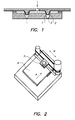
- the present invention relates to an apparatus having improved recording quality in inkjet printing systems having a shuttling print head and more specifically an ink tank for such an apparatus having a stable pressure in the supply chamber to such a print head.
- an inkjet printer In an inkjet printer drops of ink are jetted out of nozzle toward a receiving layer which may be e.g. specially coated paper.
- a receiving layer which may be e.g. specially coated paper.
- an inkjet print head has an array of nozzles, each nozzle jetting ink to different locations at the same time.
- the ink is jetted out of the nozzles by use of e.g. a thermal or piezoelectric actuators creating a pressure wave. It is normally the intention that the size of the droplets can be kept constant or that there is a good control of the droplet size in printers capable of recording variable droplet sizes.
- FIG. 1 an inkjet print head is depicted with capillary tubes 1 having a nozzle end and a inlet end.
- an actuator 2 is provided for causing a pressure wave expelling the ink out of the nozzle at the end.
- ink is fed to the print head from an ink tank.
- the ink forming a meniscus 3 at the nozzle end in the capillary tubes 1 is influenced by surface tension forces.
- Another force acting upon the ink is the "hydrostatic" pressure caused by gravity due to the height of the ink above the meniscus 3.
- the level of the ink in the ink tank determines the pressure of the ink in the print head.
- a positive ink pressure will arise due to the vertical height difference between ink level and nozzles.
- Some types of print heads need a stable negative ink pressure at the nozzle area for good printing. To reach finally a negative pressure at the nozzles, this positive pressure can be neutralised by applying a negative pressure above the ink in the header tank.
- a problem is that in order to obtain constant or controllable recording quality the negative pressure in the head and tank is to be kept constant or within a small range.
- Inkjet print heads can be as large as the transversal size of an image or text to be printed but usually the size of the print head is smaller. Page wide print heads are still expensive and less reliable than smaller types.
- Fig. 2 gives a view of how an inkjet printer composes a whole image.
- a receiving sheet 4 e.g. a sheet of paper is transported in one direction (transport direction indicated by arrow A) and passed gradually underneath the printing station.
- the print head 5 which has a size smaller than the receiving sheet 4 shuttles transversal (indicated by arrow B) over it and consecutively records one or more lines when shutting over the sheet 4 paper.
- the image is composed gradually.
- an ink tank containing an ink supply is coupled to the print head 5.
- Small printers usually have a small cartridge, optionally with integrated print head nozzles, containing only a limited amount of ink. When empty these cartridges have to be replaced.
- High end inkjet printers having a high throughput or large formats however consume a large amount of ink.
- the inkjet print head of a high end printer is coupled an ink tank mounted on the shuttling carriage carrying the print head. This ink tank is called a header tank and can be refilled out of a large capacity ink tank which is stationary.
- EP-A-1 142 713 a system for refilling a header tank is described wherein refilling can be done during printing.
- the header tank on the shuttling carriage is connected by flexible tubes to a feeder tank.
- the main tank is pressurised and when a replenishing valve is opened ink is pressed by the air pressure from the feeder tank to the header tank during printing operation.
- a supplementary valve is placed between the header tank and the print head.
- a further problem is that to allow a compact staggering of print heads, the ink tank dimensions should be smaller than the print head itself.
- the present invention solves above mentioned drawbacks by providing an header tank having functional elements arranged symmetrical to the centre plane perpendicular to the direction of movement of the shuttling carriage of the printer.
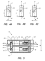
- FIG. 3A depicts a cross section perpendicular to the shuttling direction of a header tank 6 according to the present invention.
- Fig. 3B shows a combination of 2 tanks having further features which will be described later on.
- Fig. 5 gives a horizontal section of the dual tank combination.
- the double pointed arrow B indicates the shuttling direction of the print carriage containing the print head and the header tank.
- Plane P is the centre plane perpendicular to this direction.
- the ink tank 6 has an ink chamber 7 and contains or is in connection with several functional elements. As functional elements are considered all features which have an influence upon the working of the ink tank 6. Several functional features can be seen in this view.
- Fig. 4A to 4C depict the ink level in an ink tank 6 during three stages.
- the ink surface in the ink chamber during state L in Fig. 4A and R in Fig. 4C is inclined due to the acceleration of the ink tank and the inertia of the ink in the ink chamber.
- a gradient of the hydrostatic pressure is created within the body of the ink.
- the feed outlet 8 is situated in the centre plane perpendicular to the direction of movement of the carriage, the height of the ink level h at the position of the outlet 8 in the ink chamber 7 is not influenced as can be seen in Fig. 4A to Fig. 4C.
- the inclination of the ink level (due to ac- and deceleration of the carriage) is pivoting symmetrically and the level height h in the middle of each tank stays stable.
- the inlet 10 When considering the location of the inlet 10 for ink replenishment into the chamber 7 it is to be avoided that inflow of the ink causes pressure changes.
- the most neutral placement of the inlet 10 is also in the centre plane of the ink chamber 7.
- the inlet 10 constructed to ensure that ink is supplied under the ink level in order to avoid drops falling into the tank causing e.g. trapping of air in bubbles etc.
- a further functional feature is the system regulating the ink level in the ink chamber. 7
- a ink movement damper 16 for dampening further pressure variations, due to the shuttling, is integrated in the ink tank 6.
- This ink movement damper 16 is located between the ink chamber 7 and the ink outlet 8 to the print head 5.
- the dimension are chosen smaller that the width of the ink chamber 7.
- the size in the shuttling direction B is less than half the size of the ink chamber 7.
- the damper 16 can be executed in the form of a labyrinth, a mesh or a porous member restricting movement of the ink near the outlet opening 8 of the ink chamber 7.
- a labyrinth is shown in the right side of the ink chamber 7.
- This damper 16 has also a important degassing function of ink flowing from ink chamber 7 into the print head. As ink is fed from the ink chamber 7 to the outlet 8. A flow of ink is induced through the damper 16. The ink is forced to take several turns through the labyrinth formed by partitions 17. Air bubbles trapped in the ink have the tendency to rise to the top, where they can join with the air above the ink level in the tank 6. The air outlet of the ink damper 16 preferably has to reach above the ink level.
- the ink feed system for the print head 5 is realised by two ink connections between ink tank 6 and print head 5.
- a first connection from the ink outlet 8 to the print head 5 is on the bottom of the ink tank 6, behind the damper 16. This opening is feeding ink into the print head 5.
- a second connection coupled to the re-flow inlet 11 will allow air-bubbles to return from the print head 5 into the ink tank 6. This is especially important if a new (empty) print head 5 is to be filled with ink.
- the height of the connection of the opening with the tank 6 is located above the ink level in the ink tank 6. Via this connection the negative pressure is also supplied to the inkjet print head 5 directly.
- the ink tank 6 is connected to a large volume vacuum container in which vacuum is sustained by a small capacity extraction pump under control of a precise pressure regulator.
- a large vacuum reserve pressure will not vary easily even during a replenishment step in which a large amount of ink is added to the header tank 6.
- the pressure of a large vacuum holder will vary only with a small amount when a relatively small volume of ink is added to the system.
- the volume of the vacuum reservoir preferably is at least 5 times larger than the volume of the ink chamber 7. More preferably the volume of the vacuum reservoir is 50 to 100 times larger than the volume of the ink chamber 7.
- the ink tank 6 can for the greater part be produced using known processes like injection moulding.
- a special coating can be applied in order to obtain oleophobic characteristics.
- assemblies of coupled ink tanks 6 having common side-walls A combination of two ink tanks is shown in Fig 5.
- a separate tank is to be provided the use of combinations of ink tanks 6 having a common side-wall 18 has a cost advantage.
- the ink tanks 6 are equipped with several mounting holes/slits 21 in order to allow easy replacement of the ink tank 6 using screws or other fastening means in the printer.
- mounting means having quick release systems are used. This can be necessary when changing ink type or colour in the inkjet printing apparatus.
Landscapes
- Ink Jet (AREA)
Priority Applications (3)
| Application Number | Priority Date | Filing Date | Title |
|---|---|---|---|
| EP02100552A EP1366908A1 (en) | 2002-05-23 | 2002-05-23 | Ink tank for feeding a shuttling inkjet printing head |
| JP2003135775A JP2003341090A (ja) | 2002-05-23 | 2003-05-14 | 往復動インキジェット印刷ヘッドへの供給用インクタンク |
| US10/438,697 US6957882B2 (en) | 2002-05-23 | 2003-05-15 | Ink tank for feeding a shuttling inkjet printing head |
Applications Claiming Priority (1)
| Application Number | Priority Date | Filing Date | Title |
|---|---|---|---|
| EP02100552A EP1366908A1 (en) | 2002-05-23 | 2002-05-23 | Ink tank for feeding a shuttling inkjet printing head |
Publications (1)
| Publication Number | Publication Date |
|---|---|
| EP1366908A1 true EP1366908A1 (en) | 2003-12-03 |
Family
ID=29414798
Family Applications (1)
| Application Number | Title | Priority Date | Filing Date |
|---|---|---|---|
| EP02100552A Withdrawn EP1366908A1 (en) | 2002-05-23 | 2002-05-23 | Ink tank for feeding a shuttling inkjet printing head |
Country Status (2)
| Country | Link |
|---|---|
| EP (1) | EP1366908A1 (OSRAM) |
| JP (1) | JP2003341090A (OSRAM) |
Cited By (7)
| Publication number | Priority date | Publication date | Assignee | Title |
|---|---|---|---|---|
| US6957882B2 (en) | 2002-05-23 | 2005-10-25 | Agfa Gevaert N. V. | Ink tank for feeding a shuttling inkjet printing head |
| WO2007012255A1 (fr) * | 2005-07-25 | 2007-02-01 | Print-Rite.Unicorn Image Products Co., Ltd. Of Zh Uhai | Cartouche d’encre pour imprimante à jet d’encre |
| EP1808298A1 (en) * | 2006-01-16 | 2007-07-18 | Seiko Epson Corporation | Liquid container |
| DE102006003055A1 (de) * | 2006-01-20 | 2007-08-02 | Phoenix Contact Gmbh & Co. Kg | Tintentank |
| WO2008064608A1 (fr) * | 2006-11-29 | 2008-06-05 | Print-Rite Technology Development Co., Ltd Of Zhuhai | Cartouche d'encre pour imprimante à jet d'encre |
| WO2009108988A1 (en) * | 2008-03-03 | 2009-09-11 | Silverbrook Research Pty Ltd | Printer having recycling ink and pressure-equalized upstream and downstream ink lines |
| CN106696466A (zh) * | 2015-07-24 | 2017-05-24 | 研能科技股份有限公司 | 墨水匣及其封盖组件 |
Families Citing this family (6)
| Publication number | Priority date | Publication date | Assignee | Title |
|---|---|---|---|---|
| JP4534245B2 (ja) * | 2004-08-04 | 2010-09-01 | リコープリンティングシステムズ株式会社 | インクジェット印刷装置 |
| CN2905437Y (zh) * | 2006-04-15 | 2007-05-30 | 珠海天威技术开发有限公司 | 墨盒 |
| JP5575456B2 (ja) * | 2009-11-05 | 2014-08-20 | 株式会社ミマキエンジニアリング | 液滴吐出装置 |
| JP6838344B2 (ja) * | 2016-10-12 | 2021-03-03 | セイコーエプソン株式会社 | 液体収容体 |
| JP7073877B2 (ja) * | 2018-04-17 | 2022-05-24 | セイコーエプソン株式会社 | 液体容器および液体消費装置 |
| JP2023066019A (ja) * | 2021-10-28 | 2023-05-15 | キヤノン株式会社 | 液体吐出装置 |
Citations (4)
| Publication number | Priority date | Publication date | Assignee | Title |
|---|---|---|---|---|
| EP0812693A1 (en) * | 1995-12-25 | 1997-12-17 | Seiko Epson Corporation | Ink-jet recording apparatus for ink cartridge |
| EP1055520A1 (en) * | 1998-02-13 | 2000-11-29 | Seiko Epson Corporation | Ink jet recorder, sub-tank unit suitable therefor, and method of recovering ink droplet discharging capability |
| EP1097814A2 (en) * | 1999-11-05 | 2001-05-09 | Seiko Epson Corporation | Ink-jet recording apparatus |
| EP1199178A1 (en) * | 2000-10-20 | 2002-04-24 | Seiko Epson Corporation | Ink cartridge for ink jet recording device |
-
2002
- 2002-05-23 EP EP02100552A patent/EP1366908A1/en not_active Withdrawn
-
2003
- 2003-05-14 JP JP2003135775A patent/JP2003341090A/ja not_active Withdrawn
Patent Citations (4)
| Publication number | Priority date | Publication date | Assignee | Title |
|---|---|---|---|---|
| EP0812693A1 (en) * | 1995-12-25 | 1997-12-17 | Seiko Epson Corporation | Ink-jet recording apparatus for ink cartridge |
| EP1055520A1 (en) * | 1998-02-13 | 2000-11-29 | Seiko Epson Corporation | Ink jet recorder, sub-tank unit suitable therefor, and method of recovering ink droplet discharging capability |
| EP1097814A2 (en) * | 1999-11-05 | 2001-05-09 | Seiko Epson Corporation | Ink-jet recording apparatus |
| EP1199178A1 (en) * | 2000-10-20 | 2002-04-24 | Seiko Epson Corporation | Ink cartridge for ink jet recording device |
Cited By (20)
| Publication number | Priority date | Publication date | Assignee | Title |
|---|---|---|---|---|
| US6957882B2 (en) | 2002-05-23 | 2005-10-25 | Agfa Gevaert N. V. | Ink tank for feeding a shuttling inkjet printing head |
| WO2007012255A1 (fr) * | 2005-07-25 | 2007-02-01 | Print-Rite.Unicorn Image Products Co., Ltd. Of Zh Uhai | Cartouche d’encre pour imprimante à jet d’encre |
| US8128209B2 (en) | 2005-07-25 | 2012-03-06 | Print-Rite•Unicorn Image Products Co., Ltd. of Zhuhai | Ink cartridge for inkjet printer |
| EP1808298A1 (en) * | 2006-01-16 | 2007-07-18 | Seiko Epson Corporation | Liquid container |
| DE102006003055A1 (de) * | 2006-01-20 | 2007-08-02 | Phoenix Contact Gmbh & Co. Kg | Tintentank |
| DE102006003055B4 (de) * | 2006-01-20 | 2008-02-07 | Phoenix Contact Gmbh & Co. Kg | Tintentank |
| WO2008064608A1 (fr) * | 2006-11-29 | 2008-06-05 | Print-Rite Technology Development Co., Ltd Of Zhuhai | Cartouche d'encre pour imprimante à jet d'encre |
| US7931359B2 (en) | 2008-03-03 | 2011-04-26 | Silverbrook Research Pty Ltd | Method of priming a printhead with concomitant replenishment of ink in an ink supply chamber |
| US7887148B2 (en) | 2008-03-03 | 2011-02-15 | Silverbrook Research Pty Ltd | Method of depriming a printhead with concomitant isolation of ink supply chamber |
| US7887170B2 (en) | 2008-03-03 | 2011-02-15 | Silverbrook Research Pty Ltd | Pressure-regulating chamber comprising float valve biased towards closure by inlet ink pressure |
| US7883189B2 (en) | 2008-03-03 | 2011-02-08 | Silverbrook Research Pty Ltd | Pressure-regulating chamber for gravity control of hydrostatic ink pressure and recycling ink supply system |
| US7980685B2 (en) | 2008-03-03 | 2011-07-19 | Silverbrook Research Pty Ltd | Ink supply system with float valve |
| WO2009108988A1 (en) * | 2008-03-03 | 2009-09-11 | Silverbrook Research Pty Ltd | Printer having recycling ink and pressure-equalized upstream and downstream ink lines |
| US8500258B2 (en) | 2008-03-03 | 2013-08-06 | Zamtec Ltd | Inkjet printer with float valve regulation of hydrostatic ink pressure |
| EP2508346A3 (en) * | 2008-03-03 | 2013-10-30 | Zamtec Limited | Printer having recycling ink and pressure-equalized upstream and downstream ink lines |
| US8651635B2 (en) | 2008-03-03 | 2014-02-18 | Zamtec Ltd | Printer with ink line dampening of ink pressure surges |
| TWI455830B (zh) * | 2008-03-03 | 2014-10-11 | Zamtec Ltd | 包含藉由入口墨水壓力朝向關閉偏移的浮閥之調壓室 |
| EP2511099A3 (en) * | 2008-03-03 | 2016-10-26 | Memjet Technology Limited | Printer with dampening of ink pressure surges in a ink supply line |
| CN106696466A (zh) * | 2015-07-24 | 2017-05-24 | 研能科技股份有限公司 | 墨水匣及其封盖组件 |
| CN106696466B (zh) * | 2015-07-24 | 2018-06-12 | 研能科技股份有限公司 | 墨水匣及其封盖组件 |
Also Published As
| Publication number | Publication date |
|---|---|
| JP2003341090A (ja) | 2003-12-03 |
Similar Documents
| Publication | Publication Date | Title |
|---|---|---|
| US6957882B2 (en) | Ink tank for feeding a shuttling inkjet printing head | |
| CN100404264C (zh) | 一种墨盒以及具有该墨盒的供墨系统 | |
| JP4036934B2 (ja) | インク配送システム | |
| US4571599A (en) | Ink cartridge for an ink jet printer | |
| US7025448B2 (en) | Fluid interconnect in a replaceable ink reservoir for pigmented ink | |
| JP4094709B2 (ja) | インクジェットプリンタ及びインクジェット・プリント方法 | |
| US5742312A (en) | Printhead cartridge having a fluid valved breather | |
| JP5468956B2 (ja) | インクジェットプリンタ | |
| KR20030080260A (ko) | 잉크 보유 및 배출 시스템, 잉크 보충 방법 및 잉크젯프린터에 사용하기 위한 잉크 서플라이 | |
| EP1366908A1 (en) | Ink tank for feeding a shuttling inkjet printing head | |
| GB2293142A (en) | Capillary regulation of ink flow in multi-chambered ink cartridge for ink jet printer. | |
| US7014306B2 (en) | Liquid reservoir apparatus | |
| US6196671B1 (en) | Ink-jet cartridge for an ink jet printer having air ingestion control | |
| JPH10128994A5 (OSRAM) | ||
| JP4995674B2 (ja) | 圧力緩衝器及びインクジェットヘッド並びにインクジェット式記録装置 | |
| JPH05318760A (ja) | インクジェット記録装置 | |
| US8657424B2 (en) | Ink supply container | |
| US7185976B2 (en) | Liquid supply system and apparatus incorporating the same | |
| JP2004524197A (ja) | 交換式インク容器およびシールを形成する方法 | |
| JPH11348305A (ja) | インクジェット記録装置 | |
| JP2000334975A (ja) | インクジェットプリンタ | |
| JPH023321A (ja) | インクカートリッジ | |
| US7419253B2 (en) | Channeling fluid flow | |
| JP2007223159A (ja) | インク収納容器及び該インク収納容器を用いたインク供給システム | |
| US7396109B2 (en) | Inkjet printing system with high drop-weight yellow |
Legal Events
| Date | Code | Title | Description |
|---|---|---|---|
| PUAI | Public reference made under article 153(3) epc to a published international application that has entered the european phase |
Free format text: ORIGINAL CODE: 0009012 |
|
| AK | Designated contracting states |
Kind code of ref document: A1 Designated state(s): AT BE CH CY DE DK ES FI FR GB GR IE IT LI LU MC NL PT SE TR |
|
| AX | Request for extension of the european patent |
Extension state: AL LT LV MK RO SI |
|
| 17P | Request for examination filed |
Effective date: 20040603 |
|
| AKX | Designation fees paid |
Designated state(s): DE FR GB |
|
| 17Q | First examination report despatched |
Effective date: 20040727 |
|
| RAP1 | Party data changed (applicant data changed or rights of an application transferred) |
Owner name: AGFA GRAPHICS N.V. |
|
| 17Q | First examination report despatched |
Effective date: 20040727 |
|
| STAA | Information on the status of an ep patent application or granted ep patent |
Free format text: STATUS: THE APPLICATION IS DEEMED TO BE WITHDRAWN |
|
| 18D | Application deemed to be withdrawn |
Effective date: 20081202 |