EP1366873A1 - Oberfräse - Google Patents
Oberfräse Download PDFInfo
- Publication number
- EP1366873A1 EP1366873A1 EP03009210A EP03009210A EP1366873A1 EP 1366873 A1 EP1366873 A1 EP 1366873A1 EP 03009210 A EP03009210 A EP 03009210A EP 03009210 A EP03009210 A EP 03009210A EP 1366873 A1 EP1366873 A1 EP 1366873A1
- Authority
- EP
- European Patent Office
- Prior art keywords
- router
- ring
- copying
- locking
- copying ring
- Prior art date
- Legal status (The legal status is an assumption and is not a legal conclusion. Google has not performed a legal analysis and makes no representation as to the accuracy of the status listed.)
- Granted
Links
- 238000003801 milling Methods 0.000 claims abstract description 40
- 238000003780 insertion Methods 0.000 description 2
- 230000037431 insertion Effects 0.000 description 2
- 239000000463 material Substances 0.000 description 1
- 239000002184 metal Substances 0.000 description 1
Images

Classifications
-
- B—PERFORMING OPERATIONS; TRANSPORTING
- B27—WORKING OR PRESERVING WOOD OR SIMILAR MATERIAL; NAILING OR STAPLING MACHINES IN GENERAL
- B27C—PLANING, DRILLING, MILLING, TURNING OR UNIVERSAL MACHINES FOR WOOD OR SIMILAR MATERIAL
- B27C5/00—Machines designed for producing special profiles or shaped work, e.g. by rotary cutters; Equipment therefor
- B27C5/10—Portable hand-operated wood-milling machines; Routers
Definitions
- the invention relates to a router, on the underside a copy ring for guiding the router along a milling template is releasably attachable to a passage opening for the passage of one extending in the axial direction. milling tool driven by the router forms.
- Such routing templates usually have one with the router mounting flange to be connected and one of these copier sleeve protruding in the direction away from the router Shape up.
- the present invention is therefore based on the object to create a router of the type mentioned at who attach a copy ring quickly and easily or can be removed.
- a router has a table unit 1 with a milling table 2 on, with its underside 3 on a workpiece to be milled is put on. Stand at a distance from the milling table 2 to each other two storage columns 4,5 from the top on to which a machine unit, not shown, is mounted, that can be adjusted along the bearing columns 4,5.
- the Machine unit contains a drive motor, a gear and a jig for an axially 6 (this runs parallel to the bearing columns 4, 5) Milling tool that turns into a when the router is switched on Rotational movement is driven.
- the milling tool penetrates a central opening 7 of the milling table 2 and through Moving the machine unit along the storage columns 4, 5 brought into a position protruding below the milling table 2 in which it is when the router is placed on a workpiece attacks the workpiece. If you move the router over the workpiece, this is processed according to the movement path.
- the milling process is to take a certain course, you can use a router with an appropriately contoured template move along, which is placed on the workpiece. You put the router with its router table 2 on it the template that the milling tool past the template runs to the workpiece.
- the copy ring 8 is composed of a when attached, rest on the underside of the router table Mounting flange 9 and a copying sleeve 10 cylindrical Shape together, centrally on the mounting flange 9 is arranged and in the position of use downwards, i.e. in the direction away from the milling table 2.
- the copy ring 8 -forms one aligned with the central opening 7 of the milling table 2 arranged passage opening 11 for the passage of the Milling tool.
- the router expediently has 3 on its underside an adjustment ring 12, which is fixed, but in its Position adjustable, is attached to the other router table.
- the Attaching the adjusting ring 12 to the other milling table can with the help of bolts 13, 14 on which either the Adjustment ring 12 or the other milling table with adjustment play sits and with which a firm connection between the adjusting ring and other milling table can be produced.
- the adjustment ring 12 is positioned at the factory on the router positions and forms an integral part of this.
- the copying ring 8 is attached to the adjusting ring 12 and locked with it so that it works in the same way as the adjusting ring 12 is adjusted.
- Each locking element 15 is a locking element arranged on the copying ring 8 16 assigned.
- the locking elements 15 from against them abutting copying ring 8 deflected against the spring force mentioned and snap when the end position of the copying ring is reached 8 under the spring force behind the respectively assigned Locking member 16, so that the copying ring 8 in the axial direction 6 is locked with the milling table 2.
- Each latching element 15 is also an actuating device 17 assigned, with the help of which the respective locking element 15 counter to the spring force in the copy ring 8 again free giving solution position can be transferred. Are they Locking elements 15 in their release position, the copying ring 8 be removed from the milling table 2.
- Each locking element 15 is pivotable on one with the milling table 2 connected pivot lever 18 arranged by the called spring force is loaded and an actuating arm - 19 forms, which can be operated from the outside.
- the operating arm 19 protrudes, in the embodiment above (see Fig. 1), from the milling table 2 and carries the actuating device at the end 17 forming grip.
- the respective locking element pivots against the spring force 15 in its release position.
- the respective pivot lever 18 is over a pivot axis pivoted on the milling table 2. This is stated in the exemplary embodiment on both sides of the respective pivot lever 18 one pivot axis part 20 or 21 from the pivot lever 18, the pivot axis parts 20 each in a bearing recess 22 and 23 of the milling table 2 are stored.
- the swivel axis parts 20, 21 can, as in the embodiment, in one piece be integrally formed on the pivot lever 18.
- the spring force that the respective pivot lever 18 on the Locked position is loaded in the embodiment applied by two leg springs 24, 25, each on one of the pivot axis parts 20, 21 between the pivot lever 18 and the respectively facing bearing recess 22 or 23 are attached.
- the two leg springs 24.25 can consist of wire-shaped material and have two protruding Spring legs 26,27, one of which is a spring leg 26 on the swivel lever 18 and the other spring leg 27 on the milling table 2 (see Fig. 3 to 5) supports.
- the Swivel lever 18 starting from its swivel axis 20, 21, upwards, i.e. extends in the direction away from the copying ring 8.
- the arrangement is such that the swivel lever 18 is a one-armed lever, so that it can be used to transfer the respective locking element 15 in the release position radially is operated inside.
- the two pivot levers 18, i.e. the associated actuators 17, thus to be pressed towards each other the copy ring 8 can be removed again. Accordingly the respective locking element 15 when plugging the Copy ring 8 with the milling table 2 deflected radially inwards and snaps into the inserted end position of the copying ring 8 radially outward behind the respective locking member 16.
- each locking element 15 is one locking projection arranged in the insertion path of the copying ring 8 28 formed. Furthermore, the respective locking member 16 by one Locking section 29 of the copying ring 8 is formed, the one the locking projection 28 locking recess in the locked state 30 limited.
- the locking recess 30 and the locking portion 29 are expediently from one made of sheet metal Copy ring 8 upright latching tab 31 educated. The latching tab 31 can be removed from the fastening flange 9 of the copying ring 8 can be bent up in one piece.
- the respective recess 30 has a circumferential direction corresponding dimension to the corresponding locking projection 28, so that even in the circumferential direction, so to speak, a lock takes place.
- the copying ring 8 centering Centering means can be arranged on the router, i.e. at the milling table 2 or on the adjusting ring 12, the copying ring 8 centering Centering means can be arranged.
- These can, for example each of a locking tab 31 assigned plug slots 33 are formed on the underside of the router, which form a guide for the locking tabs 31 when these through the plug-in slots 33 to the locking projections 28 are pushed.
Landscapes
- Life Sciences & Earth Sciences (AREA)
- Engineering & Computer Science (AREA)
- Mechanical Engineering (AREA)
- Wood Science & Technology (AREA)
- Forests & Forestry (AREA)
- Milling, Drilling, And Turning Of Wood (AREA)
Abstract
Description
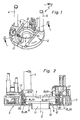
- Fig. 1
- die Tischeinheit einer Oberfräse mit zwei hochstehenden Lagersäulen in schematischer Schrägansicht, wobei an den Lagersäulen das nicht dargestellte Maschinenaggregat mit dem Antriebsmotor, dem zugehörigen Getriebe und der Einspannvorrichtung für das Fräswerkzeug höhenverstellbar gelagert ist,
- Fig. 2
- die Tischeinheit nach Fig. 1 im Querschnitt gemäß der Schnittlinie II-II in vergrößerter Darstellung, wobei der Kopierring an der Oberfräse angeordnet, jedoch nicht verriegelt ist, da sich die beiden Rastelemente in ihrer Lösestellung befinden,
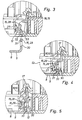
- Fig. 3
- den in Fig. 2 durch die strichpunktierte Kreislinie angegebenen Ausschnitt in vergrößerter Darstellung, wobei der Kopierring jedoch von der Oberfräse getrennt ist, so dass die Fig. 3 der Situation beispielsweise vor dem Einstecken des Kopierrings entspricht,
- Fig. 4
- den gleichen Ausschnitt, jedoch mit angestecktem und verrastetem Kopierring,
- Fig. 5
- wiederum den gleichen Ausschnitt, wobei die gleiche Situation wie in Fig. 2 gezeigt ist, und
- Fig. 6
- den Kopierring zusammen mit einem an der Oberfräse montierten Justierring (die sonstige Oberfräse ist weggelassen) in schematischer Schrägansicht, wobei die beiden Ringe mit Abstand zueinander dargestellt sind.
Claims (13)
- Oberfräse, an deren Unterseite ein Kopierring zum Führen der Oberfräse entlang einer Frässchablone lösbar befestigbar ist, der eine Durchtrittsöffnung für den Durchtritt eines sich in axialer Richtung erstreckenden, von der Oberfräse angetriebenen Fräswerkzeugs bildet, dadurch gekennzeichnet, dass der Kopierring (8) an die Oberfräse ansteckbar und beim Zusammenstecken in axialer Richtung (6) lösbar mit dieser verrastbar ist.
- Oberfräse nach Anspruch 1, dadurch gekennzeichent, dass an der Oberfräse mindestens ein quer zur axialen Richtung (6) entgegen einer Federkraft bewegbares Rastelement (15) angeordnet ist, das beim Zusammenstecken vom Kopierring (8) ausgelenkt wird und beim Erreichen der Endlage des Kopierrings (8) unter der Federkraft hinter ein Rastglied (16) des Kopierrings (8) schnappt, wobei das mindestens eine Rastelement (15) mittels einer Betätigungseinrichtung (17) entgegen der Federkraft in eine den Kopierring (8) wieder frei gebende Lösestellung überführbar ist.
- 0berfräse nach Anspruch 2, dadurch gekennzeichnet, dass mindestens zwei im wesentlichen diametral zueinander angeordnete Rastelemente (15) vorhanden sind, denen jeweils ein Rastglied (16) am Kopierring (8) zugeordnet ist.
- 0berfräse nach Anspruch 2 oder 3, dadurch gekennzeichnet, dass jedes Rastelement (15) an einem schwenkbar mit der Oberfräse verbundenen Schwenkhebel (18) angeordnet ist, der durch die Federkraft belastet ist und einen von außen her betätigbaren Betätigungsarm (19) bildet, bei dessen Betätigung das Rastelement (15) in die Lösestellung verschwenkt wird.
- Oberfräse nach Anspruch 4, dadurch gekennzeichnet, dass sich der Schwenkhebel (18), ausgehend von seiner Schwenkachse (20, 21), nach oben, in Richtung vom Kopierring (8)weg, erstreckt.
- Oberfräse nach einem der Ansprüche 2 bis 5, dadurch gekennzeichnet, dass das mindestens eine Rastelement (15) beim Zusammenstecken nach radial innen hin ausgelenkt wird und in der Endlage des Kopierrings (8) nach radial außen geschnappt ist.
- Oberfräse nach Anspruch 5 und 6, dadurch gekennzeichnet, dass der Schwenkhebel (18) ein einarmiger Hebel ist, so dass der Schwenkhebel (18) zum Überführen des Rastelements (15) in die Lösestellung nach radial innen hin betätigt wird.
- Oberfräse nach einem der Ansprüche 2 bis 7, dadurch gekennzeichnet, dass das mindestens eine Rastelement (15) von einem im Steckweg des Kopierrings (8) angeordneten Rastvorsprung (28) und das mindestens eine Rastglied (16) von einer Rastpartie (29) des Kopierrings (8) gebildet wird, die eine den Rastvorsprung (28) im verrasteten Zustand aufnehmende Rastausnehmung (30) begrenzt.
- Oberfräse nach Anspruch 8, dadurch gekennzeichnet, dass die Rastausnehmung (30) und die Rastpartie (29) von einer vom Kopierring (8) hochstehenden Verrastungslasche (31) gebildet werden.
- Oberfräse nach Anspruch 9, dadurch gekennzeichnet, dass die Verrastungslasche (31) von einem Befestigungsflansch (9) des Kopierrings (8) einstückig hochgebogen ist.
- Oberfräse nach einem der Ansprüche 8 bis 10, dadurch gekennzeichnet, dass die Rastausnehmung (30) in Umfangsrichtung eine dem Rastvorsprung (28) entsprechende Abmessung aufweist.
- Oberfräse nach einem der Ansprüche 1 bis 11, dadurch gekennzeichnet, dass an der Oberfräse den Kopierring (8) zentrierende Zentriermittel angeordnet sind.
- Oberfräse nach einem der Ansprüche 1 bis 12, dadurch gekennzeichnet, dass die Oberfräse an ihrer Unterseite (3) einen Lage justierbar angeordneten Justierring (12) aufweist, an den der Kopierring (8) ansteckbar und mit dem der Kopierring (8) verrastbar ist.
Applications Claiming Priority (2)
| Application Number | Priority Date | Filing Date | Title |
|---|---|---|---|
| DE10223893 | 2002-05-29 | ||
| DE2002123893 DE10223893B4 (de) | 2002-05-29 | 2002-05-29 | Oberfräse |
Publications (2)
| Publication Number | Publication Date |
|---|---|
| EP1366873A1 true EP1366873A1 (de) | 2003-12-03 |
| EP1366873B1 EP1366873B1 (de) | 2009-08-05 |
Family
ID=29414245
Family Applications (1)
| Application Number | Title | Priority Date | Filing Date |
|---|---|---|---|
| EP20030009210 Expired - Lifetime EP1366873B1 (de) | 2002-05-29 | 2003-04-23 | Oberfräse |
Country Status (2)
| Country | Link |
|---|---|
| EP (1) | EP1366873B1 (de) |
| DE (2) | DE10223893B4 (de) |
Cited By (4)
| Publication number | Priority date | Publication date | Assignee | Title |
|---|---|---|---|---|
| EP1886777A1 (de) * | 2006-08-08 | 2008-02-13 | Festool GmbH | Oberfräse |
| EP2783821A3 (de) * | 2013-03-25 | 2014-11-12 | Mafell AG | Oberfräse |
| EP3192622A1 (de) * | 2016-01-18 | 2017-07-19 | Power Box AG | Werkzeugmaschine |
| WO2017125811A3 (en) * | 2016-01-18 | 2017-09-08 | Power Box Ag | Power tool |
Families Citing this family (2)
| Publication number | Priority date | Publication date | Assignee | Title |
|---|---|---|---|---|
| EP1563969B1 (de) * | 2004-02-13 | 2007-03-07 | Festool GmbH | Staubabsaugvorrichtung einer Oberfräse |
| DE102023105164A1 (de) * | 2023-03-02 | 2024-09-05 | MAFELL Aktiengesellschaft | Aufnahmeeinheit für eine Bearbeitungsmaschine, Bearbeitungsmaschine mit einer Aufnahmeeinheit, Zubehörteil und Verfahren zum Anbringen eines Zubehörteils an einer Bearbeitungsmaschine |
Citations (3)
| Publication number | Priority date | Publication date | Assignee | Title |
|---|---|---|---|---|
| DE1002118B (de) * | 1953-03-23 | 1957-02-07 | Gotthold Haffner Fa | Vorsatzgeraet fuer elektrische Handfraesmaschinen |
| US5016691A (en) * | 1990-06-19 | 1991-05-21 | Lucien Bernier | Apparatus for centering template guide on router |
| US5370165A (en) * | 1993-04-14 | 1994-12-06 | Ritter Manufacturing, Inc. | Attachment for a portable router |
Family Cites Families (2)
| Publication number | Priority date | Publication date | Assignee | Title |
|---|---|---|---|---|
| GB2260728B (en) * | 1991-10-25 | 1994-04-27 | Black & Decker Inc | Router template guides |
| DE29513331U1 (de) * | 1995-08-19 | 1996-12-12 | Robert Bosch Gmbh, 70469 Stuttgart | Winkelschleiferschutzhaube |
-
2002
- 2002-05-29 DE DE2002123893 patent/DE10223893B4/de not_active Expired - Fee Related
-
2003
- 2003-04-23 DE DE50311770T patent/DE50311770D1/de not_active Expired - Lifetime
- 2003-04-23 EP EP20030009210 patent/EP1366873B1/de not_active Expired - Lifetime
Patent Citations (3)
| Publication number | Priority date | Publication date | Assignee | Title |
|---|---|---|---|---|
| DE1002118B (de) * | 1953-03-23 | 1957-02-07 | Gotthold Haffner Fa | Vorsatzgeraet fuer elektrische Handfraesmaschinen |
| US5016691A (en) * | 1990-06-19 | 1991-05-21 | Lucien Bernier | Apparatus for centering template guide on router |
| US5370165A (en) * | 1993-04-14 | 1994-12-06 | Ritter Manufacturing, Inc. | Attachment for a portable router |
Cited By (11)
| Publication number | Priority date | Publication date | Assignee | Title |
|---|---|---|---|---|
| EP1886777A1 (de) * | 2006-08-08 | 2008-02-13 | Festool GmbH | Oberfräse |
| EP2783821A3 (de) * | 2013-03-25 | 2014-11-12 | Mafell AG | Oberfräse |
| EP3192622A1 (de) * | 2016-01-18 | 2017-07-19 | Power Box AG | Werkzeugmaschine |
| WO2017125813A1 (en) * | 2016-01-18 | 2017-07-27 | Power Box Ag | Power tool |
| WO2017125811A3 (en) * | 2016-01-18 | 2017-09-08 | Power Box Ag | Power tool |
| EP3192624A3 (de) * | 2016-01-18 | 2017-10-11 | Power Box AG | Handwerkzeugmaschine |
| CN107530896A (zh) * | 2016-01-18 | 2018-01-02 | 能源盒子股份公司 | 电动工具 |
| CN107614220A (zh) * | 2016-01-18 | 2018-01-19 | 能源盒子股份公司 | 刳刨机装置的改进 |
| US10449689B2 (en) | 2016-01-18 | 2019-10-22 | Power Box Ag | Improvements to router apparatus |
| US10596674B2 (en) | 2016-01-18 | 2020-03-24 | Power Box Ag | Improvements to router apparatus |
| AU2017201344B2 (en) * | 2016-01-18 | 2022-03-10 | Power Box Ag | Improvements to router apparatus |
Also Published As
| Publication number | Publication date |
|---|---|
| DE50311770D1 (de) | 2009-09-17 |
| DE10223893B4 (de) | 2009-08-13 |
| EP1366873B1 (de) | 2009-08-05 |
| DE10223893A1 (de) | 2003-12-18 |
Similar Documents
| Publication | Publication Date | Title |
|---|---|---|
| DE3120271C2 (de) | Vorrichtung zum Verbinden eines Geschwindigkeitsmessers mit einer flexiblen Welle | |
| EP1170079B2 (de) | Bohrfutter | |
| DE102009027570A1 (de) | Vorrichtung zum Positionieren und Befestigen einer Einrichtung, insbesondere eines Handgriffs an einem Elektrowerkzeug | |
| EP3256089B1 (de) | Spannklaue zur anbringung an einer gleitschiene eines operationstisches | |
| DE29905017U1 (de) | Anordnung zur Montage eines Bohrwerkzeugs an einer Vorlegewelle eines motorangetriebenen Handbohrers | |
| DE29522207U1 (de) | Bohrfutter | |
| DE102008042113A1 (de) | Zusatzhandgriff für eine Handwerkzeugmaschine | |
| EP1799396B1 (de) | Wechselvorrichtung für spannköpfe mit mehreren spannbacken | |
| WO2020234116A1 (de) | Radhalter | |
| DE2831140C2 (de) | ||
| EP0707923A1 (de) | Messer, insbesondere Entgratemesser für Kunststoffteile | |
| DE102016102058B4 (de) | Drehmomentschlüssel mit der Möglichkeit zur Aufnahme von Antriebsköpfen | |
| DE102006025137B4 (de) | Schneidwerkzeuge und Führungseinrichtung | |
| DE102008000158A1 (de) | Handgriff für ein insbesondere motorisch angetriebenes Werkzeug | |
| DE19913022B4 (de) | Korbspule für Draht, insbesondere für Schweißdraht | |
| EP1366873A1 (de) | Oberfräse | |
| DE60038654T2 (de) | Klemmhalterung für Stütz- und Verbindungselemente | |
| DE1923718B2 (de) | Handhabenklemmrastbefestigung am vierkantdorn eines schlosses | |
| DE1791013C2 (de) | Kupplung für den Anschluß eines zahnärztlichen Hand- oder Winkelstückes an einen als Kleinstmotor ausgebildeten elektrischen Antriebsmotor | |
| DE102009038371A1 (de) | Kupplungselement | |
| DE2036065A1 (de) | Mechanische Verbindung | |
| DE102012219058A1 (de) | Schnellspannmutter | |
| DE202009004936U1 (de) | Schraubenpositioniervorrichtung mit der Möglichkeit zum Einsatz in zwei Werkzeugköpfen mit unterschiedlichen Abmessungen | |
| EP2915638A1 (de) | Verbindungselement für wenigstens zwei plattenförmige Elemente eines Werkzeugs, Verwendung eines Verbindungselements sowie Stanz- oder Ausbrechwerkzeug | |
| AT509140B1 (de) | Fixiervorrichtung für einen bohrkopf |
Legal Events
| Date | Code | Title | Description |
|---|---|---|---|
| PUAI | Public reference made under article 153(3) epc to a published international application that has entered the european phase |
Free format text: ORIGINAL CODE: 0009012 |
|
| AK | Designated contracting states |
Kind code of ref document: A1 Designated state(s): AT BE BG CH CY CZ DE DK EE ES FI FR GB GR HU IE IT LI LU MC NL PT RO SE SI SK TR |
|
| AX | Request for extension of the european patent |
Extension state: AL LT LV MK |
|
| 17P | Request for examination filed |
Effective date: 20031010 |
|
| AKX | Designation fees paid |
Designated state(s): DE FR GB IT |
|
| GRAP | Despatch of communication of intention to grant a patent |
Free format text: ORIGINAL CODE: EPIDOSNIGR1 |
|
| GRAS | Grant fee paid |
Free format text: ORIGINAL CODE: EPIDOSNIGR3 |
|
| GRAA | (expected) grant |
Free format text: ORIGINAL CODE: 0009210 |
|
| AK | Designated contracting states |
Kind code of ref document: B1 Designated state(s): DE FR GB IT |
|
| REG | Reference to a national code |
Ref country code: GB Ref legal event code: FG4D Free format text: NOT ENGLISH |
|
| REF | Corresponds to: |
Ref document number: 50311770 Country of ref document: DE Date of ref document: 20090917 Kind code of ref document: P |
|
| PLBE | No opposition filed within time limit |
Free format text: ORIGINAL CODE: 0009261 |
|
| STAA | Information on the status of an ep patent application or granted ep patent |
Free format text: STATUS: NO OPPOSITION FILED WITHIN TIME LIMIT |
|
| 26N | No opposition filed |
Effective date: 20100507 |
|
| PG25 | Lapsed in a contracting state [announced via postgrant information from national office to epo] |
Ref country code: IT Free format text: LAPSE BECAUSE OF FAILURE TO SUBMIT A TRANSLATION OF THE DESCRIPTION OR TO PAY THE FEE WITHIN THE PRESCRIBED TIME-LIMIT Effective date: 20090805 |
|
| REG | Reference to a national code |
Ref country code: DE Ref legal event code: R082 Ref document number: 50311770 Country of ref document: DE Representative=s name: PATENTANWAELTE MAGENBAUER & KOLLEGEN, DE |
|
| REG | Reference to a national code |
Ref country code: DE Ref legal event code: R081 Ref document number: 50311770 Country of ref document: DE Owner name: FESTOOL GROUP GMBH & CO. KG, DE Free format text: FORMER OWNER: FESTOOL GMBH, 73240 WENDLINGEN, DE Effective date: 20121119 Ref country code: DE Ref legal event code: R082 Ref document number: 50311770 Country of ref document: DE Representative=s name: PATENTANWAELTE MAGENBAUER & KOLLEGEN, DE Effective date: 20121119 Ref country code: DE Ref legal event code: R081 Ref document number: 50311770 Country of ref document: DE Owner name: FESTOOL GMBH, DE Free format text: FORMER OWNER: FESTOOL GMBH, 73240 WENDLINGEN, DE Effective date: 20121119 Ref country code: DE Ref legal event code: R082 Ref document number: 50311770 Country of ref document: DE Representative=s name: PATENTANWAELTE MAGENBAUER & KOLLEGEN PARTNERSC, DE Effective date: 20121119 |
|
| REG | Reference to a national code |
Ref country code: DE Ref legal event code: R082 Ref document number: 50311770 Country of ref document: DE Representative=s name: PATENTANWAELTE MAGENBAUER & KOLLEGEN PARTNERSC, DE |
|
| REG | Reference to a national code |
Ref country code: DE Ref legal event code: R082 Ref document number: 50311770 Country of ref document: DE Representative=s name: PATENTANWAELTE MAGENBAUER & KOLLEGEN PARTNERSC, DE Effective date: 20141104 Ref country code: DE Ref legal event code: R081 Ref document number: 50311770 Country of ref document: DE Owner name: FESTOOL GMBH, DE Free format text: FORMER OWNER: FESTOOL GROUP GMBH & CO. KG, 73240 WENDLINGEN, DE Effective date: 20141104 |
|
| REG | Reference to a national code |
Ref country code: FR Ref legal event code: PLFP Year of fee payment: 14 |
|
| REG | Reference to a national code |
Ref country code: FR Ref legal event code: PLFP Year of fee payment: 15 |
|
| REG | Reference to a national code |
Ref country code: FR Ref legal event code: PLFP Year of fee payment: 16 |
|
| PGFP | Annual fee paid to national office [announced via postgrant information from national office to epo] |
Ref country code: GB Payment date: 20220425 Year of fee payment: 20 Ref country code: FR Payment date: 20220420 Year of fee payment: 20 Ref country code: DE Payment date: 20220329 Year of fee payment: 20 |
|
| REG | Reference to a national code |
Ref country code: DE Ref legal event code: R071 Ref document number: 50311770 Country of ref document: DE |
|
| REG | Reference to a national code |
Ref country code: GB Ref legal event code: PE20 Expiry date: 20230422 |
|
| P01 | Opt-out of the competence of the unified patent court (upc) registered |
Effective date: 20230519 |
|
| PG25 | Lapsed in a contracting state [announced via postgrant information from national office to epo] |
Ref country code: GB Free format text: LAPSE BECAUSE OF EXPIRATION OF PROTECTION Effective date: 20230422 |