EP1366855A1 - Chamfer processing method and device for plate material - Google Patents
Chamfer processing method and device for plate material Download PDFInfo
- Publication number
- EP1366855A1 EP1366855A1 EP03012072A EP03012072A EP1366855A1 EP 1366855 A1 EP1366855 A1 EP 1366855A1 EP 03012072 A EP03012072 A EP 03012072A EP 03012072 A EP03012072 A EP 03012072A EP 1366855 A1 EP1366855 A1 EP 1366855A1
- Authority
- EP
- European Patent Office
- Prior art keywords
- plate material
- grinding belts
- pivot
- holder
- grinding
- Prior art date
- Legal status (The legal status is an assumption and is not a legal conclusion. Google has not performed a legal analysis and makes no representation as to the accuracy of the status listed.)
- Granted
Links
- 239000000463 material Substances 0.000 title claims abstract description 92
- 238000003672 processing method Methods 0.000 title claims abstract description 10
- 230000033001 locomotion Effects 0.000 claims abstract description 30
- 230000002596 correlated effect Effects 0.000 claims description 4
- 238000000034 method Methods 0.000 description 11
- 239000000203 mixture Substances 0.000 description 5
- 238000004519 manufacturing process Methods 0.000 description 3
- 230000000994 depressogenic effect Effects 0.000 description 2
- 230000001105 regulatory effect Effects 0.000 description 2
- 229910000831 Steel Inorganic materials 0.000 description 1
- 230000005540 biological transmission Effects 0.000 description 1
- 230000000694 effects Effects 0.000 description 1
- 238000009434 installation Methods 0.000 description 1
- 239000002184 metal Substances 0.000 description 1
- 238000005498 polishing Methods 0.000 description 1
- 239000010959 steel Substances 0.000 description 1
Images




Classifications
-
- F—MECHANICAL ENGINEERING; LIGHTING; HEATING; WEAPONS; BLASTING
- F16—ENGINEERING ELEMENTS AND UNITS; GENERAL MEASURES FOR PRODUCING AND MAINTAINING EFFECTIVE FUNCTIONING OF MACHINES OR INSTALLATIONS; THERMAL INSULATION IN GENERAL
- F16G—BELTS, CABLES, OR ROPES, PREDOMINANTLY USED FOR DRIVING PURPOSES; CHAINS; FITTINGS PREDOMINANTLY USED THEREFOR
- F16G5/00—V-belts, i.e. belts of tapered cross-section
- F16G5/16—V-belts, i.e. belts of tapered cross-section consisting of several parts
-
- B—PERFORMING OPERATIONS; TRANSPORTING
- B24—GRINDING; POLISHING
- B24B—MACHINES, DEVICES, OR PROCESSES FOR GRINDING OR POLISHING; DRESSING OR CONDITIONING OF ABRADING SURFACES; FEEDING OF GRINDING, POLISHING, OR LAPPING AGENTS
- B24B19/00—Single-purpose machines or devices for particular grinding operations not covered by any other main group
- B24B19/26—Single-purpose machines or devices for particular grinding operations not covered by any other main group for grinding workpieces with arcuate surfaces, e.g. parts of car bodies, bumpers or magnetic recording heads
-
- B—PERFORMING OPERATIONS; TRANSPORTING
- B24—GRINDING; POLISHING
- B24B—MACHINES, DEVICES, OR PROCESSES FOR GRINDING OR POLISHING; DRESSING OR CONDITIONING OF ABRADING SURFACES; FEEDING OF GRINDING, POLISHING, OR LAPPING AGENTS
- B24B21/00—Machines or devices using grinding or polishing belts; Accessories therefor
- B24B21/002—Machines or devices using grinding or polishing belts; Accessories therefor for grinding edges or bevels
-
- B—PERFORMING OPERATIONS; TRANSPORTING
- B24—GRINDING; POLISHING
- B24B—MACHINES, DEVICES, OR PROCESSES FOR GRINDING OR POLISHING; DRESSING OR CONDITIONING OF ABRADING SURFACES; FEEDING OF GRINDING, POLISHING, OR LAPPING AGENTS
- B24B47/00—Drives or gearings; Equipment therefor
- B24B47/02—Drives or gearings; Equipment therefor for performing a reciprocating movement of carriages or work- tables
- B24B47/04—Drives or gearings; Equipment therefor for performing a reciprocating movement of carriages or work- tables by mechanical gearing only
-
- B—PERFORMING OPERATIONS; TRANSPORTING
- B24—GRINDING; POLISHING
- B24B—MACHINES, DEVICES, OR PROCESSES FOR GRINDING OR POLISHING; DRESSING OR CONDITIONING OF ABRADING SURFACES; FEEDING OF GRINDING, POLISHING, OR LAPPING AGENTS
- B24B9/00—Machines or devices designed for grinding edges or bevels on work or for removing burrs; Accessories therefor
Definitions
- This invention relates to a chamfer processing method and device, and more particularly to the R-chamfer (synonymous with bevel) process (hereinafter referred to only as chamfer for clarity) to mass-produce specialized components such as the end faces of small metal plate-like parts (hereinafter referred to as plate material) with complicated shapes, including the traverse element for a drive belt for a Continuously Variable Transmission (CVT) (hereinafter only referred to as the traverse element).
- CVT Continuously Variable Transmission
- barrel grinding also known as barrel polishing
- the chamfer size is small. This type of chamfer is unsuitable for a deeper chamfer required to manufacture the traverse element. Accordingly, in considering the generally known technology to perform chamfer processing of the traverse element, the above-mentioned subject matter remains to be solved.
- the aforementioned technology chamfers the plate material end faces by pivoting (i.e., rocking motion) the plate material while in contact with a grinding belt (also called an abrasive belt). Because of the large pivot radius of the plate material in contact with the grinding belt, only a large curvature radius can be carried out.
- the traverse element has a specialized shape. The inside slot which forms the neck of the traverse element becomes narrow, which makes deep chamfer processing difficult to accomplish.
- the present invention has been made for the purpose of solving the circumstances mentioned above. Accordingly, although the present invention uses grinding belts, this chamfer processing method and device enables chamfer in a small curvature radius without applying a heavy tension load on the grinding belts, and performs uniform deep chamfer processing of multiple plate material simultaneously.
- chamfer processing is carried out by making plate material end faces come in contact with rotating grinding belts.
- the grinding surfaces of the opposing side by side grinding belts are on the centerline in the thickness direction of the plate material.
- the center point is considered the pivot point as seen from the plate material end faces and in distance is smaller than the thickness of the plate material.
- Pivot motion of the plate material is carried out in the rotating direction of the grinding belts.
- chamfer processing is carried out in a virtually orthogonal array (right angled crosses) with the surfaces of multiple plate material end faces in the rotating direction of the opposed grinding belts.
- the chamfer processing of each plate material is carried out by making the end faces come in contact with the rotating grinding belts. Processing is further characterized by a pivot motion radius length that is within the overall length of the plate material and carried out on the centerline of each plate material.
- the present invention method in the above-described composition is carried out on the end faces of each plate material while in contact with equal pressure grinding belts.
- the plate material pivot forward and backward in the rotating direction of the grinding belts in multiple plate material holders.
- each plate material holder synchronously pivots in the same radius.
- the difference of the pivot in the same forward direction as the rotating direction of the grinding belts is applied to the pivot in the backward direction as the rotating direction of the grinding belts.
- the preferred balance in the amount of chamfer formed before and after the plate material end faces can be regulated.
- the upper surface of the holder guide supports from beneath each correlated plate material holder, and forms the pivot radius in the concave circular arc.
- This circular arc also supports the back and forth sliding of each plate material holder along its circular arc.
- To implement the above-mentioned chamfer processing method in the above-described composition is characterized by grinding belts arranged in a mode to be rotated by a driver pulley and follower pulley.
- a plurality of holder guides is arranged facing the grinding belts along the rotating direction of these belts.
- the upper surface of the holder guides is formed in a concave circular arc, which serves as the radius for the pivot motion of the work holders.
- a plurality of work holders carry out the pivot motion along the circular arc arranged in the upper sliding surface of each holder guide.
- Multiple work holders retain each correlated plate material and face the plane of each plate material to carry out the chamfer processing in an orthogonal direction with the rotating grinding belts.
- An interlocking linkage mechanism synchronizes the pivot motion of each work holder carried out on each holder guide.
- This linkage mechanism is equipped with a source drive for the reciprocating motion.
- the grinding surface of the rotating grinding belts is held against each work holder retaining each plate material in contact with the chamfer end faces and executed in combination with the pivot motion of each work holder.
- the chamfer processing device of the present invention in the above-mentioned composition is further comprised of the belt guides installed along the sides of the free moving grinding belts for maintaining the straight rotation of these grinding belts. Additionally, in the adopted composition, a plurality of free moving belt regulators are installed above the butting part of eachholder guide against the grinding belts. Furthermore, the grinding belts are composed of free movement to the work holders, as is the case with the belt guides and belt regulators. The purpose of assuming the free movement composition of the grinding belts, belt guides, and belt regulators is because of the set up of each work holder processing object by a multiple plate material loader and unloader, thus involving a bulk (batch set) loading and unloading process.
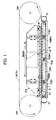
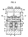
- the base frame of the present invention is comprised of base 1 and work support plates 2 and 3.
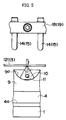
- Work support plates 2 and 3 are mounted upright on the upper front and back surfaces of base 1 (FIG. 2 upper left and right sides).
- work W tapered part of chamfer plate material W
- taper parts 2a and 3a On opposite plane of the upper end and inner surface of work support plates 2 and 3, the tapered part of chamfer plate material W (hereinafter referred to as work W) comes in contact with taper parts 2a and 3a.
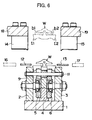
- guide stand 4 runs along its longitudinal length. As illustrated in FIG. 4 cross-sectional view, guide stand 4 is mounted in an upright position on top of base 1 in the shape of an abbreviated inverted T.
- sliders 5 and 6 Inserted on both sides of guide stand 4, sliders 5 and 6 are arranged in position by shoulders 4a and 4b, respectively.
- Sliders 5 and 6, which are located along the lengthwise dimension of work support plates 2 and 3 in several places (FIG. 1 shows 3 places), are horizontally attached to support rods 7 and 8 by means of bearings 7a and 8a on the outer sides.
- Sliders 5 and 6, contain structure holes 5a and 6a, which slide freely in the lengthwise direction of base 1.
- U-shaped slots 5b and 6b enclose a loosely inserted pivot shaft 11 to be mentioned later.
- slider drive source D is set up at both ends of sliders 5 and 6.
- Holder guide 9 is bridged between sliders 5 and 6.
- Holder guide 9 forms a block shaped rectangle which is not quite square.
- the upper surface of holder 9 forms a concave circular arc 9a which supports the pivot shaft motion of work holders 10 described later.
- Circular arc 9a is a concentric circle centered on the center of the R-chamfer where chamfer processing of work W is carried out in work holders 10.
- Work holders 10 are defined as a block shape (FIG. 4) yet when observed from the front view roughly resembles a triangle.
- work holders 10 in context are synonymous with plate material holders which contain work W.
- work holders 10 are realized as the plate material holders; however, the actual instance of work holders 10 is not limited to plate material holders.
- Work holders 10 may be realized in other holders.
- work holders 10 serves as the best example.
- When evenly positioned at the base side work holders 10 on the side of sliding surface 10a slides through circular arc 9a of holder guide 9.
- Support slot 10b maintains work W in the top part.
- Each work holder 10 is constructed with a centrally-located pivot motion axis (hereinafter referred to as pivot shaft 11)passed through U-shaped slots 5b and 6b in sliders 5 and 6, as well as supported by structure holes 2b and 3b in work support plates 2 and 3, respectively.
- the aforementioned sliders 5 and 6 containing U-shaped slots 5b and 6b, holder guide 9 and pivot shaft 11 constitute the pivot motion in the interlocking linkage mechanism of work holders 10.
- each work W set in each work holder 10 On the opposite side above work support plates 2 and 3 and work holders 10, the grinding process is carried out on each work W set in each work holder 10.
- the alignment of two grinding belts 12 and 13 are regulated by belt regulators 14 and 15 which press down from above.
- belt guides 16 and 17 support and lead the grinding belts 12 and 13 from the outside of each installed position.
- twenty-one belt regulators 14 and 15 are situated in a row above the butting part of each holder guide 9.
- each of the belt regulators 14 and 15 are set up in each of the respective installation frames 18 and 19 as part of the frame support mechanism FS equipped with side blocks, cylinders, etc.
- the frame support mechanism FS moves freely in the up and down - back and forth directions (FIG. 2 left and right). Also, as shown in FIG. 1, driver pulley DP and follower pulley FP surround the above-mentioned grinding belts 12 and 13.
- the tip sides of above-mentioned belt guides 16 and 17, form freely in proximity to the outer side of each the grinding belts 12 and 13.
- the axial stop for belt guides 16 and 17 is limited by work support plates 2 and 3. While centered on the axis and standing upright, belt guides 16 and 17 are installed to freely tilt/incline as necessary.
- Work W in this case of operation consists of chamfer processing the upper end faces of steel band acceptance slots b1 and b2 located above torque transfer planes t1 and t2.
- Each work W batch set is placed into each work holder 10 with a loader (not shown). During the time of this set up, each work holder 10 is in the upright position as in FIG. 5.
- grinding belts 12 and 13 comprised of driver pulley DP and follower pulley FP
- belt regulators 14 and 15 comprised of frame support mechanism FS and belt guides 16 and 17 shunt (shift) in position so as to not to become an obstruction with the loader of work W(refer to FIG. 6).
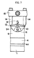
- shunted grinding belts 12 and 13, belt regulators 14 and 15, and belt guides 16 and 17 return to a predetermined position and will be in a chamfer grinding process standby condition (refer to FIGS. 7-9).
- sliders 5 and 6 are driven by drive source D and the reciprocating motion is carried out by sliders 5 and 6 alternating in the left and right directions as shown in FIG. 1.
- the amount of reciprocation strokes can be freely adjusted as the pivot angle is reflected in work holders 10.
- work holders 10 can only be adjusted within the range that does not deviate from the concave circular arc 9a of holder guide 9.
- adjustment of the stroke speed and pivot edge stop time is also possible.
- pivot shaft 11 of each work holder 10 supported by U-shaped slots 5b and 6b, pivot along the concave circular arc formed in the upper surface of each holder guide 9 .
- a "burr” can occur on one side of the end face and a "sag” (shear droop) on the opposite side. If chamfer processing work is carried out under these conditions using the same pivot angle, the amount of chamfer may differ. Accordingly, the chamfer processing pivot angle can be adjusted and set at different angles left and right.
- chamfer processing is carried out in a virtually orthogonal array (right angled crosses) with the surface of multiple plate material end faces in the rotating direction of the opposed grinding belts.
- the chamfer processing of each plate material is carried out by making the end faces come in contact with the rotating grinding belts.
- Processing is further characterized by a pivot motion radius length that is within the overall length of the plate material and carried out on the centerline of each plate material. Since simultaneous chamfer processing of multiple plate material can be accomplished, the advantages and achievable effects of the present invention are as follows:
Landscapes
- Engineering & Computer Science (AREA)
- Mechanical Engineering (AREA)
- General Engineering & Computer Science (AREA)
- Grinding And Polishing Of Tertiary Curved Surfaces And Surfaces With Complex Shapes (AREA)
- Finish Polishing, Edge Sharpening, And Grinding By Specific Grinding Devices (AREA)
Abstract
Description
Claims (9)
- A chamfer processing method for plate material (W) comprised of:making said plate material (W)end faces come in contact with rotating grinding belts (12,13);wherein the grinding surfaces of the opposing side by side grinding belts (12,13) are on the centerline in the thickness direction of said plate material (W);the center point is considered the pivot point as seen from said plate material (W) end faces and in distance is smaller than the thickness of said plate material (W);the pivot motion of said plate material (W) is carried out in the rotating direction of said grinding belts (12,13).
- The chamfer processing method for plate material (W) of claim 1, wherein chamfer processing is carried out on the end faces of each plate material (W) while in contact with equal pressure grinding belts (12,13);
said plate material (W) pivot forward and backward in the rotating direction of the grinding belts (12,13) in multiple plate material holders. - The chamfer processing method for plate material (W) of claim 1, wherein each plate material holder synchronously pivots in the same radius.
- The chamfer processing method for plate material (W) of claim 1, wherein the difference of the pivot in the same forward direction as the rotating direction of said grinding belts (12, 13) is applied to the pivot in the backward direction as the rotating direction of said grinding belts (12,13).
- The chamfer processing method for plate material (W) of claim 1, wherein the pivot of each of said plate material holders, the upper surface of the holder guide (9) supports from beneath each correlated plate material holder, and forms the pivot radius in the concave circular arc (9a);
said circular arc (9a) also supports the back and forth sliding of each plate material holder along its circular arc (9a). - The chamfer processing device is characterized by said grinding belts (12,13) arranged in a mode to be rotated by a driver pulley (DP) and follower pulley (FP);
a plurality of holder guides (9) is arranged facing said grinding belts (12,13) along the rotating direction of said grinding belts (12,13);
the upper surface of said holder guides (9) is formed in a concave circular arc (9a), which serves as the radius for the pivot motion of the work holders (10);
a plurality of work holders (10) carry out the pivot motion in the circular arc (9a) arranged in the upper sliding surface (10a) of each holder guide (9);
multiple work holders (10) retain each correlated plate material (W) and face the plane of each plate material (W) to carry out the chamfer processing in an orthogonal direction with the rotating grinding belts (12,13);
an interlocking linkage mechanism synchronizes the pivot motion of each work holder (10) carried out on each holder guide (9);
the linkage mechanism is equipped with a source drive (D) for the reciprocating motion;
the grinding surface of the rotating grinding belts (12,13) is held against each work holder (10) retaining each plate material (W) in contact with the chamfer end faces and executed in combination with the pivot motion of each work holder (10). - The chamfer processing device in claim 6 further comprises belt guides (16,17) installed along the sides of the free moving grinding belts (12,13) for maintaining the straight rotation of said grinding belts (12,13).
- The chamfer processing device in claim 6 further comprises a plurality of free moving belt regulators (14,15) installed above the butting part of each holder guide (9) against said grinding belts (12,13).
- Whichever plate material (W) is in the chamfer processing device in claim 6 further comprises said grinding belts (12,13) composed of free movement to said work holders (10), as is the case of with said belt guides (16,17) and belt regulators (14,15).
Applications Claiming Priority (2)
| Application Number | Priority Date | Filing Date | Title |
|---|---|---|---|
| JP2002157738A JP3759473B2 (en) | 2002-05-30 | 2002-05-30 | Method and apparatus for chamfering plate material |
| JP2002157738 | 2002-05-30 |
Publications (2)
| Publication Number | Publication Date |
|---|---|
| EP1366855A1 true EP1366855A1 (en) | 2003-12-03 |
| EP1366855B1 EP1366855B1 (en) | 2008-09-17 |
Family
ID=29417231
Family Applications (1)
| Application Number | Title | Priority Date | Filing Date |
|---|---|---|---|
| EP03012072A Expired - Lifetime EP1366855B1 (en) | 2002-05-30 | 2003-05-28 | Chamfer processing method and device for plate material |
Country Status (4)
| Country | Link |
|---|---|
| US (1) | US7033255B2 (en) |
| EP (1) | EP1366855B1 (en) |
| JP (1) | JP3759473B2 (en) |
| DE (1) | DE60323560D1 (en) |
Cited By (1)
| Publication number | Priority date | Publication date | Assignee | Title |
|---|---|---|---|---|
| WO2016102072A1 (en) | 2014-12-23 | 2016-06-30 | Robert Bosch Gmbh | An endless metal band with a coated surface, a drive belt provided with the endless metal band and method for shaping the drive belt |
Families Citing this family (7)
| Publication number | Priority date | Publication date | Assignee | Title |
|---|---|---|---|---|
| JP6144057B2 (en) * | 2013-01-29 | 2017-06-07 | ダイハツ工業株式会社 | Polishing element for continuously variable transmission belt component |
| CN107738171A (en) * | 2017-10-12 | 2018-02-27 | 江西省玛柏建材有限公司 | More one-shot forming, polishing lines devices |
| CN109434634A (en) * | 2018-11-29 | 2019-03-08 | 广东顶固集创家居股份有限公司 | Automatic edging machine |
| CN112658390B (en) * | 2020-12-21 | 2023-04-18 | 成都金杉玻璃工艺有限公司 | Refrigerator glass board layer frame card strip chamfer device |
| CN115338725B (en) * | 2022-09-16 | 2023-12-08 | 江苏库纳实业有限公司 | Aluminum profile surface treatment equipment |
| CN118905790B (en) * | 2024-10-11 | 2025-06-17 | 江苏嘉宇装饰材料有限公司 | A continuous aluminum veneer rounding processing device |
| CN119634839B (en) * | 2025-01-15 | 2025-06-10 | 力同铝业(无锡)有限公司 | Chamfering equipment for aluminum plate processing |
Citations (4)
| Publication number | Priority date | Publication date | Assignee | Title |
|---|---|---|---|---|
| US4281483A (en) * | 1978-01-31 | 1981-08-04 | Volvo Car B.V. | Method of curving supporting surfaces of driving belt elements |
| JPS5919663A (en) * | 1982-07-27 | 1984-02-01 | Toyota Motor Corp | Groove part beveling method |
| EP0110263A2 (en) * | 1982-11-20 | 1984-06-13 | Toyota Jidosha Kabushiki Kaisha | Chamfering method for a curved slot corner |
| JPS61152362A (en) * | 1984-12-25 | 1986-07-11 | Fuji Heavy Ind Ltd | V block continuous processing method for stepless speed change belt, and continuous processing device therefor |
Family Cites Families (8)
| Publication number | Priority date | Publication date | Assignee | Title |
|---|---|---|---|---|
| US2637951A (en) * | 1950-05-04 | 1953-05-12 | Libbey Owens Ford Glass Co | Sheet edging apparatus |
| US2860459A (en) * | 1958-06-06 | 1958-11-18 | Wally J Presmyk | Tool grinding mechanism |
| US4257195A (en) * | 1979-08-20 | 1981-03-24 | Appelgren Donald W | Deburring and chamfering fixture |
| JP2798347B2 (en) * | 1993-07-08 | 1998-09-17 | 信越半導体株式会社 | Wafer notch polishing machine |
| JPH07328830A (en) | 1994-06-03 | 1995-12-19 | Murata Mach Ltd | Plate material working device |
| JPH07328829A (en) | 1994-06-03 | 1995-12-19 | Murata Mach Ltd | Chamfering device for plate material |
| JP3588986B2 (en) | 1997-09-02 | 2004-11-17 | 日産自動車株式会社 | Plate material chamfering method and chamfering device |
| US6129615A (en) * | 1999-10-27 | 2000-10-10 | Continental Machines, Inc. | Deburring machine |
-
2002
- 2002-05-30 JP JP2002157738A patent/JP3759473B2/en not_active Expired - Fee Related
-
2003
- 2003-05-28 EP EP03012072A patent/EP1366855B1/en not_active Expired - Lifetime
- 2003-05-28 US US10/446,118 patent/US7033255B2/en not_active Expired - Fee Related
- 2003-05-28 DE DE60323560T patent/DE60323560D1/en not_active Expired - Lifetime
Patent Citations (4)
| Publication number | Priority date | Publication date | Assignee | Title |
|---|---|---|---|---|
| US4281483A (en) * | 1978-01-31 | 1981-08-04 | Volvo Car B.V. | Method of curving supporting surfaces of driving belt elements |
| JPS5919663A (en) * | 1982-07-27 | 1984-02-01 | Toyota Motor Corp | Groove part beveling method |
| EP0110263A2 (en) * | 1982-11-20 | 1984-06-13 | Toyota Jidosha Kabushiki Kaisha | Chamfering method for a curved slot corner |
| JPS61152362A (en) * | 1984-12-25 | 1986-07-11 | Fuji Heavy Ind Ltd | V block continuous processing method for stepless speed change belt, and continuous processing device therefor |
Non-Patent Citations (2)
| Title |
|---|
| PATENT ABSTRACTS OF JAPAN vol. 008, no. 108 (M - 297) 19 May 1984 (1984-05-19) * |
| PATENT ABSTRACTS OF JAPAN vol. 010, no. 353 (M - 539) 28 November 1986 (1986-11-28) * |
Cited By (1)
| Publication number | Priority date | Publication date | Assignee | Title |
|---|---|---|---|---|
| WO2016102072A1 (en) | 2014-12-23 | 2016-06-30 | Robert Bosch Gmbh | An endless metal band with a coated surface, a drive belt provided with the endless metal band and method for shaping the drive belt |
Also Published As
| Publication number | Publication date |
|---|---|
| US20040005846A1 (en) | 2004-01-08 |
| EP1366855B1 (en) | 2008-09-17 |
| JP3759473B2 (en) | 2006-03-22 |
| DE60323560D1 (en) | 2008-10-30 |
| US7033255B2 (en) | 2006-04-25 |
| JP2003340696A (en) | 2003-12-02 |
Similar Documents
| Publication | Publication Date | Title |
|---|---|---|
| US7033255B2 (en) | Chamfer processing method and device for plate material | |
| KR102103330B1 (en) | Ingot cutting method and wire saw | |
| EP2283968A2 (en) | Polishing method for a workpiece and polishing tool used for the polishing method | |
| CN107110295B (en) | An endless metal belt with a coated surface, a drive belt provided with the endless metal belt, and a method for forming the drive belt | |
| US6881126B2 (en) | Traction drive rolling element and method of forming the same | |
| CN214489972U (en) | Chamfering mechanism and chamfering machine with same | |
| CN100346900C (en) | Method for forming a transverse element for a push belt for a continously variable transmission | |
| JP2018158428A (en) | Wire saw and cutting processing method | |
| CN105538524A (en) | Tail portion pressing mechanism, silicon ingot squaring and cutting device and silicon ingot squaring and cutting method | |
| CN109772961A (en) | Bending machine | |
| JP2744135B2 (en) | Method and apparatus for cutting coiled wire | |
| NL2030297B1 (en) | Blanking method and blanking device | |
| CN1923454A (en) | Slipping member and machine tool with same | |
| CN109176284A (en) | Mobile phone center polishing clamp and its milling drum | |
| JP6555098B2 (en) | Transport device | |
| KR20150061313A (en) | Transfer mold for reducing raw materials | |
| KR200414570Y1 (en) | Automatic polishing device | |
| KR101147210B1 (en) | Transfer mold for reducing raw materials | |
| CN213858686U (en) | Polishing forming machine for processing multi-station light guide plate | |
| CN117464537B (en) | Aluminum profile polishing processing device and processing line | |
| CN117067098B (en) | Grinding tool kit and grinding equipment for finishing rolling surface of tapered roller | |
| CN222470509U (en) | A precision punching machine capable of automatically feeding materials | |
| CN219633343U (en) | Automatic edging equipment for rectangular magnetic sheets | |
| KR20200112080A (en) | exclusive apparatus for face milling and chamfering of metal case | |
| CN211614541U (en) | Gear shaping machine clamping device for servo electric cylinder |
Legal Events
| Date | Code | Title | Description |
|---|---|---|---|
| PUAI | Public reference made under article 153(3) epc to a published international application that has entered the european phase |
Free format text: ORIGINAL CODE: 0009012 |
|
| AK | Designated contracting states |
Kind code of ref document: A1 Designated state(s): AT BE BG CH CY CZ DE DK EE ES FI FR GB GR HU IE IT LI LU MC NL PT RO SE SI SK TR |
|
| AX | Request for extension of the european patent |
Extension state: AL LT LV MK |
|
| 17P | Request for examination filed |
Effective date: 20040115 |
|
| 17Q | First examination report despatched |
Effective date: 20040331 |
|
| AKX | Designation fees paid |
Designated state(s): DE FR GB NL |
|
| GRAP | Despatch of communication of intention to grant a patent |
Free format text: ORIGINAL CODE: EPIDOSNIGR1 |
|
| GRAS | Grant fee paid |
Free format text: ORIGINAL CODE: EPIDOSNIGR3 |
|
| GRAA | (expected) grant |
Free format text: ORIGINAL CODE: 0009210 |
|
| AK | Designated contracting states |
Kind code of ref document: B1 Designated state(s): DE FR GB NL |
|
| REG | Reference to a national code |
Ref country code: GB Ref legal event code: FG4D |
|
| REF | Corresponds to: |
Ref document number: 60323560 Country of ref document: DE Date of ref document: 20081030 Kind code of ref document: P |
|
| PLBE | No opposition filed within time limit |
Free format text: ORIGINAL CODE: 0009261 |
|
| STAA | Information on the status of an ep patent application or granted ep patent |
Free format text: STATUS: NO OPPOSITION FILED WITHIN TIME LIMIT |
|
| 26N | No opposition filed |
Effective date: 20090618 |
|
| PGFP | Annual fee paid to national office [announced via postgrant information from national office to epo] |
Ref country code: GB Payment date: 20130522 Year of fee payment: 11 Ref country code: DE Payment date: 20130522 Year of fee payment: 11 |
|
| PGFP | Annual fee paid to national office [announced via postgrant information from national office to epo] |
Ref country code: NL Payment date: 20130516 Year of fee payment: 11 Ref country code: FR Payment date: 20130531 Year of fee payment: 11 |
|
| REG | Reference to a national code |
Ref country code: DE Ref legal event code: R119 Ref document number: 60323560 Country of ref document: DE |
|
| REG | Reference to a national code |
Ref country code: NL Ref legal event code: V1 Effective date: 20141201 |
|
| GBPC | Gb: european patent ceased through non-payment of renewal fee |
Effective date: 20140528 |
|
| REG | Reference to a national code |
Ref country code: DE Ref legal event code: R119 Ref document number: 60323560 Country of ref document: DE Effective date: 20141202 |
|
| PG25 | Lapsed in a contracting state [announced via postgrant information from national office to epo] |
Ref country code: NL Free format text: LAPSE BECAUSE OF NON-PAYMENT OF DUE FEES Effective date: 20141201 |
|
| REG | Reference to a national code |
Ref country code: FR Ref legal event code: ST Effective date: 20150130 |
|
| PG25 | Lapsed in a contracting state [announced via postgrant information from national office to epo] |
Ref country code: DE Free format text: LAPSE BECAUSE OF NON-PAYMENT OF DUE FEES Effective date: 20141202 |
|
| PG25 | Lapsed in a contracting state [announced via postgrant information from national office to epo] |
Ref country code: FR Free format text: LAPSE BECAUSE OF NON-PAYMENT OF DUE FEES Effective date: 20140602 Ref country code: GB Free format text: LAPSE BECAUSE OF NON-PAYMENT OF DUE FEES Effective date: 20140528 |