EP1366820B1 - Spotting pin - Google Patents
Spotting pin Download PDFInfo
- Publication number
- EP1366820B1 EP1366820B1 EP03010698A EP03010698A EP1366820B1 EP 1366820 B1 EP1366820 B1 EP 1366820B1 EP 03010698 A EP03010698 A EP 03010698A EP 03010698 A EP03010698 A EP 03010698A EP 1366820 B1 EP1366820 B1 EP 1366820B1
- Authority
- EP
- European Patent Office
- Prior art keywords
- solution
- spotting
- tip
- pin
- holding portion
- Prior art date
- Legal status (The legal status is an assumption and is not a legal conclusion. Google has not performed a legal analysis and makes no representation as to the accuracy of the status listed.)
- Expired - Fee Related
Links
Images


Classifications
-
- B—PERFORMING OPERATIONS; TRANSPORTING
- B01—PHYSICAL OR CHEMICAL PROCESSES OR APPARATUS IN GENERAL
- B01L—CHEMICAL OR PHYSICAL LABORATORY APPARATUS FOR GENERAL USE
- B01L3/00—Containers or dishes for laboratory use, e.g. laboratory glassware; Droppers
- B01L3/02—Burettes; Pipettes
- B01L3/0241—Drop counters; Drop formers
- B01L3/0244—Drop counters; Drop formers using pins
- B01L3/0248—Prongs, quill pen type dispenser
-
- B—PERFORMING OPERATIONS; TRANSPORTING
- B01—PHYSICAL OR CHEMICAL PROCESSES OR APPARATUS IN GENERAL
- B01L—CHEMICAL OR PHYSICAL LABORATORY APPARATUS FOR GENERAL USE
- B01L3/00—Containers or dishes for laboratory use, e.g. laboratory glassware; Droppers
- B01L3/02—Burettes; Pipettes
- B01L3/0241—Drop counters; Drop formers
- B01L3/0262—Drop counters; Drop formers using touch-off at substrate or container
-
- B—PERFORMING OPERATIONS; TRANSPORTING
- B01—PHYSICAL OR CHEMICAL PROCESSES OR APPARATUS IN GENERAL
- B01L—CHEMICAL OR PHYSICAL LABORATORY APPARATUS FOR GENERAL USE
- B01L2200/00—Solutions for specific problems relating to chemical or physical laboratory apparatus
- B01L2200/06—Fluid handling related problems
- B01L2200/0605—Metering of fluids
-
- B—PERFORMING OPERATIONS; TRANSPORTING
- B01—PHYSICAL OR CHEMICAL PROCESSES OR APPARATUS IN GENERAL
- B01L—CHEMICAL OR PHYSICAL LABORATORY APPARATUS FOR GENERAL USE
- B01L2400/00—Moving or stopping fluids
- B01L2400/02—Drop detachment mechanisms of single droplets from nozzles or pins
- B01L2400/022—Drop detachment mechanisms of single droplets from nozzles or pins droplet contacts the surface of the receptacle
- B01L2400/025—Drop detachment mechanisms of single droplets from nozzles or pins droplet contacts the surface of the receptacle tapping tip on substrate
-
- B—PERFORMING OPERATIONS; TRANSPORTING
- B01—PHYSICAL OR CHEMICAL PROCESSES OR APPARATUS IN GENERAL
- B01L—CHEMICAL OR PHYSICAL LABORATORY APPARATUS FOR GENERAL USE
- B01L2400/00—Moving or stopping fluids
- B01L2400/04—Moving fluids with specific forces or mechanical means
- B01L2400/0403—Moving fluids with specific forces or mechanical means specific forces
- B01L2400/0406—Moving fluids with specific forces or mechanical means specific forces capillary forces
-
- Y—GENERAL TAGGING OF NEW TECHNOLOGICAL DEVELOPMENTS; GENERAL TAGGING OF CROSS-SECTIONAL TECHNOLOGIES SPANNING OVER SEVERAL SECTIONS OF THE IPC; TECHNICAL SUBJECTS COVERED BY FORMER USPC CROSS-REFERENCE ART COLLECTIONS [XRACs] AND DIGESTS
- Y10—TECHNICAL SUBJECTS COVERED BY FORMER USPC
- Y10T—TECHNICAL SUBJECTS COVERED BY FORMER US CLASSIFICATION
- Y10T436/00—Chemistry: analytical and immunological testing
- Y10T436/25—Chemistry: analytical and immunological testing including sample preparation
- Y10T436/2575—Volumetric liquid transfer
Definitions
- the present invention relates to a macroarray spotting pin for spotting a spotting solution containing biopolymers on a water-absorbing support, such as a nylon membrane, during the macroarray manufacturing process.
- Macroarrays are conventionally manufactured by spotting multiple kinds of spotting solutions containing biopolymers such as DNA, RNA, and proteins on a support, such as a nylon membrane.
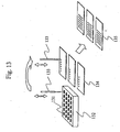
- Fig. 13 illustrates the principle of manufacture of a macroarray.
- a microplate 132 houses multiple kinds of spotting solutions to be spotted, including a DNA solution 131.
- the support for the macroarray is comprised of a nylon membrane 134.
- the DNA solution 131 is carried by a spotting pin 133 and then spotted on the nylon membrane 134, and this process is repeated, thereby producing a plurality of macroarrays 135 on which the multiple kinds of DNA solutions are spotted.
- Various types of spotting pins for the manufacture of macroarrays have been developed. Examples include a split-type pin capable of sequential spotting based on the capillary action similar to that which occurs in the fountain-pen tip, and a solid-type pin in which a spotting solution is caused to adhere to the pin tip
- the split-type pins are advantageous in that they do not require the solution to be adhered to the tip of the pins before each spotting and that they are resistant to drying, for example, it is still difficult to sequentially spot equal amounts.
- a spotting pin according to the invention which is capable of carrying a solution based on the capillary phenomena and which can have its tip split.
- the invention provides a spotting pin for spotting a solution on a water-absorbing support, comprising:
- the solution in the solution supply portion can be filled into the solution holding portion of the first member by a capillary action.
- the second member is caused to slide relative to the first member against the force of the biasing member, in order to separate the solution holding portion of the first member and the solution supply portion of the second member.
- a predetermined amount of the solution is carried in the through-hole of the first member due to a capillary action.
- the tip of the first member is brought into contact with the absorptive support, so that the predetermined amount of solution carried by the solution holding portion of the first member is absorbed into the absorptive support, forming a spot.
- the solution supply portion of the second member is brought into contact with the solution holding portion of the first member by the force of the biasing member. Consequently, the solution holding portion of the first member that has been empty can be re-filled with the solution from the solution supply portion due to a capillary action.
- equal amounts of the solution can be sequentially spotted on the absorptive support.
- the second member may comprise a body and a branch portion extending from the body in a direction opposite the tip of the first member.
- the branch portion acts as a mount via which the spotting pin can be fixed to the pin head of spotting equipment.
- the first member is driven relative to the second member by a pin or the like protruding from the pin head of the spotting equipment.
- the second member may comprise a body and a branch portion extending from the body in a direction of the tip of the first member, and the tip of the branch portion may protrude beyond the tip of the first member when the solution supply portion of the second member is in contact with the solution holding portion of the first member.
- the branch portion comes into contact with the support and thus functions as a stopper for separating the solution holding portion of the first member from the solution supply portion of the second member.
- the spotting pin is fixed to the spotting equipment by having the rear end of the first member fixed to the pin head.
- a large amount of a biopolymer solution can be supplied to the spotting pin, so that more spots can be created at once by a single charging of the solution.
- a line connecting the tip of the first member and the center of the solution reservoir may be either parallel or non-parallel to the sliding direction of the second member.
- the periphery of the tip surface of the first member is cut in order to reduce the area of contact with the support. It is also preferable that the periphery of the tip of the second member opposite the back surface of the tip of the first member be cut in order to reduce the area of contact with the back surface of the tip of the first member.
- the biasing member may be a compression spring disposed between the inner wall of the rear end of the first member and the second member.
- the compression spring acts to push the second member in the direction of the tip of the first member.
- the first and second members may be made of austenitic stainless steel. By using austenitic stainless steel as the material for the spotting pin, the strength and acid and chemical resistance can be improved.
- the sliding portions of the first and second members are preferably diamond-coated.
- the invention provides a spotting pin for spotting a solution on a water-absorbing support, comprising:
- This spotting pin is an application of the principle of the spotting pins described above, and it comprises a plurality of solution supply portions and pin tips that are connected to one another.
- This embodiment allows multiple spots to be simultaneously formed on the water-absorbing support.
- a disposable spotting pin can be provided at reduced costs. Further, contamination of the solution, which is potentially problematic for recycling purposes, can be avoided.
- the spotting pin according to the invention can be used for spotting any kind of biopolymers, such as DNA, RNA, proteins, and mixtures thereof.
- biopolymers such as DNA, RNA, proteins, and mixtures thereof.
- film-like supports in general with water-absorbing properties for macroarray purposes such as nylon membranes, can be used.
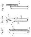
- Figs. 1(a) to 1(c) show assembled and disassembled views of an example of the spotting pin according to the invention.
- a spotting pin 10 includes a second member 12 that is slidably accommodated within an outer, cylindrical first member 11.
- the first member 11 includes a solution holding portion 13 formed at the tip thereof.
- the solution holding portion 13 is formed by a capillary tube of about 0.05 to 0.5mm in diameter and about 0.5 to 2mm in length.
- the volume of the solution holding portion 13 may be in the range of from 4 to 1600nL.
- the second member 12 includes a cylindrical body 18 provided with a solution supplying portion 14 formed along the center axis thereof.
- the solution supplying portion 14 is formed by a relatively long capillary tube of about 0.05 to 0.5mm in diameter.
- the second member 12 also includes an L-shaped branch portion 15 extending once sideways from a rear end of the body and then extending in parallel with the central axis of the body towards its rear.
- the spotting pin 10 is assembled as follows. First, a slit 17 is formed in the side wall of the cylindrical first member 11 along the axis thereof as shown in Fig. 1(a), the first member 11 having the solution holding portion 13 at the tip formed by the capillary tube. Then, as shown in Fig. 1(b), the second member 12 and a compression spring 16 are inserted into the first member 11, with the L-shaped branch portion 15 extending from the body 18 of the second member 12 sliding along the slit 17. Finally, the end of the cylindrical first member 11 is closed, as shown in Fig. 1(c). The thus obtained spotting pin 10 is then mounted on spotting equipment (not shown) by securely attaching the tip of the L-shaped branch portion 15 extending from the second member 12 to a pin head of the spotting equipment.
- the compression spring 16 inserted in the rear space of the first member 11 urges the body 18 of the second member 12 towards the tip of the first member 11.
- the first and second members 11 and 12 are made of austenitic stainless steel, which has excellent mechanical strength as well as acid and chemical resistance.
- the inner wall and the slit 17 of the first member 11 acts as a guide as the surface of the body 18 of the second member 12 axially slides on the inner wall of the first member 11. When there is no external force applied, the body 18 of the second member 12 is urged toward the tip of the first member by the action of the compression spring 16.
- the capillary tube constituting the solution holding portion 14 of the second member 12 is brought into contact and communicated with the capillary tube constituting the solution holding portion 13 formed at the tip of the first member 11, forming a single long continuous tube at the center of the spotting pin.
- the second member 12 slides relative to the first member 11 in the direction of compressing the compression spring 16, a gap is created between the solution holding portion 13 of the first member 13 and the solution supply portion 14 of the second member 12.
- the slit 17 of the first member 11 acts as an air passage allowing the air sealed inside the first member to be let out or the outside air to be introduced into the first member.
- the tip of the cylindrical first member 11 has its periphery cut such that it has a reduced area of contact with the support.
- the tip of the second member 12 opposite the solution holding portion 13 of the first member 11 has its periphery cut such that it has a reduced area of contact with the back surface of the tip of the first member.
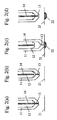
- Figs. 2(a) to 2(d) illustrate the operation of the spotting pin shown in Fig. 1(c) as it spots a solution of DNA or the like on a water-absorbing support such as, for example, a nylon membrane.
- the capillary tube constituting the solution holding portion of the first member is communicated with the capillary tube constituting the solution supply portion of the second member.
- the capillary tubes act as if they were a single capillary tube, when the tip of the first member 11 is dipped into the DNA solution.
- the DNA solution travels through the solution holding portion 13 of the first member 11 based on a capillary action and fills the solution supply portion 14 of the second member 12, as shown in Fig. 2(a).
- the second member 12 is caused to slide within the first member 11 against the force of the compression spring 16, as shown in Fig. 2(b).
- This causes the capillary tube constituting the solution holding portion 13 of the first member 11 be separated from the capillary tube constituting the solution supply portion 14 of the second member 12, thus severing the capillary action at the point of separation.
- the DNA solution remains in the solution holding portion 13 of the first member 11 due to the capillary action.
- a predetermined amount of the DNA solution remains which is determined by the dimensions of the capillary tube forming the solution holding portion.
- the tip of the first member 11 is brought into contact with the water-absorbing support 21, such as a nylon membrane.
- the DNA solution held by the solution holding portion 13 of the first member 11 is absorbed by the water-absorbing support 21, thus forming a spot 22, as shown in Fig. 2(c).
- the tip of the first member 11 is raised above the water-absorbing support 21, with the solution holding portion 13 of the first member 11 still separated from the solution supply portion 14 of the second member 12.
- the solution holding portion 13 of the first member 11 is now empty.
- the solution holding portion 13 of the first member 11 is brought into contact with the solution supply portion 14 of the second member 12 by the action of the compression spring 16, as shown in Fig. 2(d).
- This causes the capillary tube constituting the solution holding portion of the first member 11 to be once again communicated with the capillary tube constituting the solution supply portion 14 of the second member 12, thus forming a single capillary tube.
- the solution held by the solution supply portion 14 of the second member 12 is shifted to the solution holding portion 13 of the first member 11 by the capillary action, thus filling the solution holding portion 13.
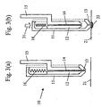
- Fig. 3(a) and 3(b) schematically show typical states of the spotting pin in operation.
- the branch portion 15 of the second member 12 of the spotting pin 10 is fixed to a pin head of spotting equipment (not shown), such that the spotting pin 10 as a whole moves up and down in response to the up/down movement of the pin head.
- Fig. 3(a) shows the spotting head in a standby state, corresponding to Fig. 2(a).
- Fig. 3(b) shows the spotting head in an operating state, corresponding to Fig. 2(c).
- Fig. 3(b) because the second member 12 of the spotting pin 10 is fixed to the pin head of the spotting equipment, it does not move.
- the first member 11 is pushed downward away from the pin head in the direction indicated by an arrow 31, and the tip comes into contact to the water-absorbing support 21.
- the predetermined amount of solution held by the solution holding portion 13 at the tip of the first member 11 is absorbed by the water-absorbing support 21, forming a spot 22.
- the compression spring 16 mounted inside the spotting pin 10 allows the pushing force to be controlled, which makes it possible to stabilize the spot shape and extend the life of the spotting pin.
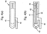
- Figs. 4(a) and 4(b) show another embodiment of the spotting pin according to the invention.
- Fig. 4(a) is a side view
- Fig. 4(b) is a cross-sectional view. While the spotting pin shown in Figs. 4(a) and 4(b) differs from that shown in Figs. 1(a) to 1(c) in the structure of a branch portion 45 extending from the body of the second member 12, other portions are substantially similar. Accordingly, the following description of the second embodiment is mainly concerned with the differences from the spotting pin shown in Figs. 1(a) to 1(c).
- a spotting pin 40 is depicted as a second member 42 is urged in the direction of compressing a compression spring 46 for ease of understanding of the structure.
- the L-shaped branch portion 45 extending from the body of the second member 42 extends forward along the axis, as opposed to that in the first embodiment shown in Fig. 1(c).
- the tip of the L-shaped branch portion 45 protrudes beyond the tip of the first member 41.
- the L-shaped branch portion 45 in this case does not function as a mount via which the spotting pin is attached to the pin head of the spotting equipment. Instead, it functions as a stopper, as will be described later.
- the spotting pin 40 of the present embodiment is mounted on the spotting equipment by fixing the rear end of the first member 41 to the pin head of the spotting equipment.
- Figs. 5(a) to 5(c) schematically show the spotting operation of the spotting pin 40 shown in Figs. 4(a) and 4(b).
- the rear end of the first member 41 is fixed to the pin head of the spotting equipment, so that as the pin head moves up and down, the spotting pin 40 also moves up and down as a whole.
- the pin head only requires a mechanism for fixing the spotting pin 40 and does not require such an additional mechanism for pushing down the pin head as required by the pin head to which the spotting pin of Fig. 1(c) is fixed.
- Fig. 5(a) shows the spotting pin 40 as it is positioned above a planned spotting position on the water-absorbing support 21.
- the tip of the L-shaped branch portion 45 of the second member 42 comes into contact with the support 21 first, as shown in Fig. 5(b).
- the pin head is further lowered, as shown in Fig. 5(c), to thereby push the first member 41 as indicated by an arrow 51, only the first member 41 slides downward against the force of the compression spring 46, with the downward movement of the second member 42 blocked by the L-shaped branch portion 45.
- the solution holding portion 43 of the first member 41 separates from the solution supply portion 44 of the second member 42, and a predetermined amount of solution is separately carried by the capillary tube constituting the solution holding portion 43 due to the capillary action.
- the amount of the solution carried by the solution holding portion 43 is determined by the dimensions of the capillary tube constituting the solution holding portion 43.
- the pin head is raised.
- the solution holding portion 43 of the first member 41 is eventually brought into contact with the solution supply portion 44 of the second member 42 by the action of the compression spring 46.
- a portion of the solution held by the solution supply portion 44 of the second member 42 then shifts into the solution holding portion 43 of the first member 41 based on the capillary action, thus filling the solution holding portion 43.
- the sequence of events thus comes back to the state shown in Fig. 5(a).
- a predetermined amount of solution can be sequentially spotted onto a plurality of water-absorbing supports 21.
- FIG. 6 is a cross-sectional view of another embodiment of the spotting pin according to the invention.
- a spotting pin 60 is similar to the spotting pin shown in Fig. 1(c) except that a solution reservoir is provided.
- a first member 61 includes a capillary tube formed at the tip constituting a solution holding portion 63.
- a second member 62 includes a solution reservoir 67 formed in an L-shaped branch portion 65.
- the L-shaped branch portion 65 extends toward the rear of the spotting pin and functions as a mount to be fixed to the pin head.
- the solution reservoir 67 is communicated with a capillary tube constituting a solution supply portion 64 of the body of the second member via a flow passage 68 with a bend.
- the pin tip is located directly below the point of application of a force 69 applied to move the spotting pin upward or downward.
- the solution reservoir 67 is capable of storing a large quantity of solution.
- the spotting pin 60 according to this embodiment allows spots of equal amounts to be sequentially formed on a number of supports with a single filling of the solution.
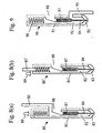
- FIG. 7 shows a cross section of another embodiment of the spotting pin according to the invention.
- This spotting pin is similar to that shown in Figs. 4(a) and 4(b) except that a solution reservoir is added.
- a first member 71 includes a capillary tube formed at the tip thereof constituting a solution holding portion 73.
- a second member 72 is provided with a solution reservoir 77 formed above a branch portion 75 that extends toward the tip of the pin and which functions as a stopper.
- the solution reservoir 77 is communicated with a capillary tube constituting a solution supply portion 74 of the body of the second member 72 by a flow passage 78 with a bend.
- the tip of the pin is located directly below the point of application of a force 79 applied from the pin head for the upward or downward movement.
- the solution reservoir 77 is capable of storing a large quantity of solution.
- the spotting pin 70 allows spots of equal amounts to be sequentially formed on a number of supports with a single filling of the solution.
- Figs. 8(a) and (b) show cross-sectional views of yet another embodiment of the spotting pin according to the invention.
- Spotting pins 80 and 80' illustrated are variations of the spotting pins described with reference to Figs. 1 to 3, in which a solution reservoir 87 is provided in a second member 82.
- a cylindrical first member 81 includes a capillary tube formed at the tip constituting a solution holding portion 83.
- a second member 82 includes a solution reservoir 87 formed above a capillary tube constituting a solution supply portion 84 from which a solution is supplied to the solution holding portion 83 of the first member 81.
- a slit is formed in the first member 81 along the axis thereof.
- a portion of the slit is enlarged in a peripheral direction in the shape of a window.
- the window forms a solution inlet 88 via which a solution can be delivered into the solution reservoir 87.
- the solution reservoir 87 is capable of storing a large quantity of solution, so that spots of equal amounts can be sequentially formed on a number of supports with a single filling of the solution.
- the spotting pin 80 shown in Fig. 8(a) includes an L-shaped branch portion 85 that protrudes sideways from the rear end of the body of the second member 82 and then extends backward along the central axis of the body.
- the spotting pin 80' shown in Fig. 8(b) includes a linear branch portion 85' that extends from the rear end of the body of the second member 82 along the central axis of the body and protrudes through an opening formed in the rear end of the first member 81'.
- the inner walls and the axial slits in the first members 81 and 81' act as a slide guide when the second member 82 slides on the inner walls of the first members 81 and 81' against the force of the compression spring 86.
- the upper end of the branch portions 85 and 85' extending upward from the second member provides a mount for fixing the spotting pin to the pin head of the spotting equipment, while the upper end of the first member 81 receives a force 89 from the pin head.
- Fig. 9 shows a cross-section of yet another embodiment of the spotting pin according to the invention.
- a spotting pin 90 is similar to that shown in Figs. 4(a) and 4(b) except that a solution reservoir is added.
- the spotting pin 90 is also similar to the spotting pin 70 shown in Fig. 7, but the location of the solution reservoir is different.
- a first member 91 includes a capillary tube formed at the tip thereof constituting a solution holding portion 93. The upper end of the first member 91 is fixed to the pin head of the spotting equipment.
- a second member 92 includes a capillary tube constituting a solution supply portion 94 for supplying the solution to the solution holding portion 93, and a solution reservoir 97 provided at the top of the solution supply portion 94. From the second member 92 extends an L-shaped branch portion 95 that functions as a stopper, protruding sideways via a slit formed in the first member 91 and then extending forward. A portion of the slit formed along the axis of the first member 91 is enlarged in a peripheral direction in the shape of a window.
- the window forms a solution inlet 98 through which the solution can be delivered to the solution reservoir 97 of the second member 92.
- the solution reservoir 97 is capable of storing a large quantity of solution, spots of equal amounts can be sequentially formed on a number of supports with a single filling of the solution.
- the inner wall and the slit of the first member 91 acts as a slide guide when the second member 92 slides on the inner wall of the first member 91 against the force of the compression spring 96.
- Fig. 10(a) and 10(b) show another embodiment of the spotting pin according to the invention.
- the spotting pin is comprised of a member 104 having a plurality of solution-reservoir equipped solution supply portions coupled with another member 103 having a plurality of solution holding portions (capillary tubes).
- This spotting pin is capable of forming a plurality of spots at once.
- the member 104 with the multiple solution-reservoir equipped solution supply portions and the member 103 with the multiple solution holding portions can be either in contact with one another, as shown in Fig. 10(a), or separated away from one another, as shown in Fig. 10(b).
- the member 103 with the multiple solution holding portions together with the member 104 multiple kinds of DNA solutions can be sequentially and quantitatively spotted.
- the two plates 103 and 104 can be detachably mounted on the spotting equipment. In this case, there is no need for a microplate for storing biopolymers.
- the member 104 By forming the member 104 having the multiple solution-reservoir equipped solution supplying portions with plastics, the member 104 can be manufactured cheaply and made disposable, and also the contamination of the solution can be prevented.
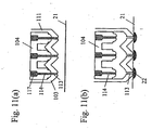
- Figs. 11(a) and 11(b) show cross-sectional views of another example of the structure of the spotting pin which allows a plurality of quantitative spots to be formed at once.
- Fig. 11(a) corresponds to Fig. 10(a)
- Fig. 11(b) corresponds to Fig. 10(b).
- the member 104 with the multiple solution-reservoir equipped solution supply portions include multiple groups of multiple capillary tubes constituting the solution supply portions 114 and multiple large-sized solution reservoirs 117 connected to the corresponding capillary tubes.
- the member 103 with the multiple solution holding portions include multiple capillary tubes constituting solution holding portions 113.
- the inner wall 111 of the member 103 functions as a guide along which the member 104 can slide on the member 103.
- Each of the solution holding portions 113, solution supply portions 114, and solution reservoirs 117 are grouped to form an independent spotting pin as described above.
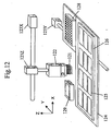
- Fig. 12 shows an example of the spotting equipment.
- the spotting equipment includes a pin head 122 on which spotting pins 121 are mounted below, an X-motor 123X for driving the pin head 122 along the X-axis direction, a Z-motor 123Z for driving the pin head 122 along the Z-axis direction, a base 124, and a Y-motor 123Y for driving the base 124 along the Y-direction.
- On the base 124 is mounted a stage 126 carrying a plurality of water-absorbing supports 125 such as nylon membranes, and a microplate 128 containing multiple kinds of solutions of biopolymers such as DNA.
- the spotting pins 121 employ the spotting pins as described above according to the invention.
- the X-and Z-direction positions of the pin head 122 are accurately controlled by the X-motor 123X and the Z-motor 123Z, and the Y-direction position of the base 124 is accurately controlled by the Y-motor 123Y.
- equal amounts of multiple kinds of solutions of biopolymers can be sequentially spotted on the multiple water-absorbing supports 125.
- the spotting pins are washed by a pin washing apparatus 129 before the next biopolymer solution is charged into the spotting pins in order to prevent the contamination of the solutions. Washing of the pins is carried out by a combination of ultrasound washing and vacuum drying.
- the pins are vacuum-dried once after use, washed with ultrasound, and then vacuum-dried once again. In this way, the contamination of the solutions can be prevented and multiple kinds of biopolymer solutions can be spotted onto a nylon membrane, for example.
- the biopolymer solution can be filled in the spotting pins of the invention in the following manner.
- the biopolymer solution is only filled in the solution holding portion at the tip of the first member before each spotting, so that a quantitative spotting can be carried out each time.
- the biopolymer solution is filled in the solution supply portion of the second member, so that a sequential spotting can be carried out.
- the solution can be filled into the solution supply portion of the second member by the capillary action.
- pins with large-volume solution reservoirs are employed as the spotting pins, and the biopolymer solution can be filled into the solution reservoirs from above.
Landscapes
- Health & Medical Sciences (AREA)
- Clinical Laboratory Science (AREA)
- Chemical & Material Sciences (AREA)
- Chemical Kinetics & Catalysis (AREA)
- Automatic Analysis And Handling Materials Therefor (AREA)
- Sampling And Sample Adjustment (AREA)
- Apparatus Associated With Microorganisms And Enzymes (AREA)
- Feeding, Discharge, Calcimining, Fusing, And Gas-Generation Devices (AREA)
Applications Claiming Priority (2)
| Application Number | Priority Date | Filing Date | Title |
|---|---|---|---|
| JP2002145130 | 2002-05-20 | ||
| JP2002145130A JP3732457B2 (ja) | 2002-05-20 | 2002-05-20 | スポットピン |
Related Child Applications (1)
| Application Number | Title | Priority Date | Filing Date |
|---|---|---|---|
| EP03103204 Division | 2003-08-18 |
Publications (2)
| Publication Number | Publication Date |
|---|---|
| EP1366820A1 EP1366820A1 (en) | 2003-12-03 |
| EP1366820B1 true EP1366820B1 (en) | 2005-03-23 |
Family
ID=29417102
Family Applications (1)
| Application Number | Title | Priority Date | Filing Date |
|---|---|---|---|
| EP03010698A Expired - Fee Related EP1366820B1 (en) | 2002-05-20 | 2003-05-13 | Spotting pin |
Country Status (4)
| Country | Link |
|---|---|
| US (1) | US6835352B2 (ja) |
| EP (1) | EP1366820B1 (ja) |
| JP (1) | JP3732457B2 (ja) |
| DE (1) | DE60300401T2 (ja) |
Families Citing this family (21)
| Publication number | Priority date | Publication date | Assignee | Title |
|---|---|---|---|---|
| US7285422B1 (en) | 1997-01-23 | 2007-10-23 | Sequenom, Inc. | Systems and methods for preparing and analyzing low volume analyte array elements |
| EP1200841A1 (en) * | 1999-08-13 | 2002-05-02 | Cartesian Technologies, Inc. | Apparatus for liquid sample handling |
| US20020142483A1 (en) * | 2000-10-30 | 2002-10-03 | Sequenom, Inc. | Method and apparatus for delivery of submicroliter volumes onto a substrate |
| GB2377707B (en) * | 2001-04-26 | 2004-10-20 | Thk Co Ltd | Microarraying head and microarrayer |
| US20030166263A1 (en) * | 2002-12-30 | 2003-09-04 | Haushalter Robert C. | Microfabricated spotting apparatus for producing low cost microarrays |
| GB0302281D0 (en) * | 2003-01-31 | 2003-03-05 | Biorobotics Ltd | Liquid transfer system |
| WO2005059650A2 (en) * | 2003-12-12 | 2005-06-30 | Parallel Synthesis Technologies, Inc. | Device and method for microcontact printing |
| JP2008506114A (ja) * | 2004-07-06 | 2008-02-28 | ユニバーシティー オブ ユタ リサーチ ファンデーション | マイクロアレイおよび他のマイクロスケール装置上に高濃度スポットを沈着させるためのスポッティング装置および方法 |
| JP2006078382A (ja) * | 2004-09-10 | 2006-03-23 | Yokogawa Electric Corp | バイオチップ作成装置 |
| US8858718B2 (en) * | 2004-09-14 | 2014-10-14 | Bti Holdings, Inc. | Plate washing system with ultrasonic cleaning of pipes and a control method thereof |
| US20060054188A1 (en) * | 2004-09-14 | 2006-03-16 | Bti Holding, Inc. | Plate washing system with ultrasonic cleaning of pipes |
| US20060054190A1 (en) * | 2004-09-14 | 2006-03-16 | Bti Holding, Inc. | Plate washing system with ultrasonic cleaning of pipes |
| WO2006094049A2 (en) * | 2005-03-01 | 2006-09-08 | Parallel Synthesis Technologies, Inc. | Polymeric fluid transfer and printing devices |
| DE112006001237T5 (de) * | 2005-05-17 | 2008-03-13 | Kyocera Corporation | Spotstift, Spotvorrichtung, Tüpfelverfahren für Flüssigkeiten sowie Herstellungsverfahren einer Einheit für biochemische Analysen |
| JP5132146B2 (ja) * | 2006-03-17 | 2013-01-30 | キヤノン株式会社 | 分析方法、分析装置、及び検体保持部材 |
| WO2009039122A2 (en) | 2007-09-17 | 2009-03-26 | Sequenom, Inc. | Integrated robotic sample transfer device |
| EP2163901A1 (de) * | 2008-09-10 | 2010-03-17 | Roche Diagnostics GmbH | Verfahren und Dosiereinrichtung zum Dosieren einer Flüssigkeit in einen Aufnahmekanal eines Testelementes zur Analyse von Körperflüssigkeiten |
| EP2506976A2 (en) * | 2009-12-03 | 2012-10-10 | Owe Owar | Pipettes, methods of use, and methods of stimulating an object of interest |
| EP2704834A2 (en) | 2011-05-06 | 2014-03-12 | Owe Orwar | Microfluidic device with holding interface, and method of use |
| US10300450B2 (en) | 2012-09-14 | 2019-05-28 | Carterra, Inc. | Method and device for depositing a substance on a submerged surface |
| JP6385800B2 (ja) * | 2014-11-11 | 2018-09-05 | 日本電子株式会社 | 液体吸引具、液体供給ユニット及び自動分析装置 |
Family Cites Families (5)
| Publication number | Priority date | Publication date | Assignee | Title |
|---|---|---|---|---|
| DE3445944C1 (de) * | 1984-12-17 | 1986-06-05 | Otto 6900 Heidelberg Mutschler | Tintenleiter fuer Roehrchenschreiber |
| US5807522A (en) * | 1994-06-17 | 1998-09-15 | The Board Of Trustees Of The Leland Stanford Junior University | Methods for fabricating microarrays of biological samples |
| US5957167A (en) * | 1997-12-18 | 1999-09-28 | Pharmacopeia, Inc. | Article for dispensing small volumes of liquid |
| US6309891B1 (en) * | 1998-09-09 | 2001-10-30 | Incyte Genomics, Inc. | Capillary printing systems |
| GB9824202D0 (en) | 1998-11-04 | 1998-12-30 | Moore David F | Liquid transfer system |
-
2002
- 2002-05-20 JP JP2002145130A patent/JP3732457B2/ja not_active Expired - Fee Related
-
2003
- 2003-05-09 US US10/434,214 patent/US6835352B2/en not_active Expired - Fee Related
- 2003-05-13 DE DE60300401T patent/DE60300401T2/de not_active Expired - Lifetime
- 2003-05-13 EP EP03010698A patent/EP1366820B1/en not_active Expired - Fee Related
Also Published As
| Publication number | Publication date |
|---|---|
| US6835352B2 (en) | 2004-12-28 |
| DE60300401T2 (de) | 2005-07-28 |
| JP2003337084A (ja) | 2003-11-28 |
| US20030215368A1 (en) | 2003-11-20 |
| JP3732457B2 (ja) | 2006-01-05 |
| DE60300401D1 (de) | 2005-04-28 |
| EP1366820A1 (en) | 2003-12-03 |
Similar Documents
| Publication | Publication Date | Title |
|---|---|---|
| EP1366820B1 (en) | Spotting pin | |
| US5770151A (en) | High-speed liquid deposition device for biological molecule array formation | |
| EP1156880B1 (en) | Apparatus and method for spotting a substrate | |
| US7258253B2 (en) | Method and system for precise dispensation of a liquid | |
| US5525515A (en) | Process of handling liquids in an automated liquid handling apparatus | |
| US20050208676A1 (en) | Device for aspirating, manipulating, mixing and dispensing nano-volumes of liquids | |
| EP2847551B1 (en) | Cartridge for dispensing a fluid | |
| WO2006053588A1 (en) | Supply arrangement with supply reservoir element and fluidic device | |
| CN101868730A (zh) | 用于分析流体样品的微流控芯片 | |
| JP2005513465A (ja) | マイクロ流体アレイ・デバイス用インターフェース部材およびホルダ | |
| US11701664B2 (en) | Analysis device and method | |
| JP2006091006A (ja) | チップ装置の製造装置及び方法 | |
| US20020072068A1 (en) | Spotting pin and device for fabricating biochips | |
| KR20020090923A (ko) | 샘플을 처리하는 장치와, 이 장치의 이용법 및, 이 장치를생산하는 방법 | |
| CN113694983B (zh) | 一种可变距移液装置及枪头变距部件 | |
| US20190250183A1 (en) | Fluid control equipment for bio-reaction, bio-reaction system and fluid control method for bio-reaction | |
| CN220835632U (zh) | 一种移液吸头 | |
| US20090123958A1 (en) | Laboratory Devices, Methods and Systems Employing Acoustic Ejection Devices | |
| WO2006032853A2 (en) | Reagent holder and testing assembly incorporating a reagent holder | |
| JP2005069830A (ja) | 分注チップとそれを用いた分析装置 | |
| CN114849806A (zh) | 自动化移液设备、多管道移液组件及移液结构 |
Legal Events
| Date | Code | Title | Description |
|---|---|---|---|
| PUAI | Public reference made under article 153(3) epc to a published international application that has entered the european phase |
Free format text: ORIGINAL CODE: 0009012 |
|
| 17P | Request for examination filed |
Effective date: 20030513 |
|
| AK | Designated contracting states |
Kind code of ref document: A1 Designated state(s): AT BE BG CH CY CZ DE DK EE ES FI FR GB GR HU IE IT LI LU MC NL PT RO SE SI SK TR |
|
| AX | Request for extension of the european patent |
Extension state: AL LT LV MK |
|
| AKX | Designation fees paid |
Designated state(s): DE FR GB |
|
| GRAP | Despatch of communication of intention to grant a patent |
Free format text: ORIGINAL CODE: EPIDOSNIGR1 |
|
| GRAS | Grant fee paid |
Free format text: ORIGINAL CODE: EPIDOSNIGR3 |
|
| GRAA | (expected) grant |
Free format text: ORIGINAL CODE: 0009210 |
|
| AK | Designated contracting states |
Kind code of ref document: B1 Designated state(s): DE FR GB |
|
| REG | Reference to a national code |
Ref country code: GB Ref legal event code: FG4D |
|
| REG | Reference to a national code |
Ref country code: IE Ref legal event code: FG4D |
|
| REF | Corresponds to: |
Ref document number: 60300401 Country of ref document: DE Date of ref document: 20050428 Kind code of ref document: P |
|
| PLBE | No opposition filed within time limit |
Free format text: ORIGINAL CODE: 0009261 |
|
| STAA | Information on the status of an ep patent application or granted ep patent |
Free format text: STATUS: NO OPPOSITION FILED WITHIN TIME LIMIT |
|
| 26N | No opposition filed |
Effective date: 20051227 |
|
| ET | Fr: translation filed | ||
| PGFP | Annual fee paid to national office [announced via postgrant information from national office to epo] |
Ref country code: FR Payment date: 20110523 Year of fee payment: 9 |
|
| PGFP | Annual fee paid to national office [announced via postgrant information from national office to epo] |
Ref country code: GB Payment date: 20110511 Year of fee payment: 9 |
|
| PGFP | Annual fee paid to national office [announced via postgrant information from national office to epo] |
Ref country code: DE Payment date: 20110511 Year of fee payment: 9 |
|
| GBPC | Gb: european patent ceased through non-payment of renewal fee |
Effective date: 20120513 |
|
| REG | Reference to a national code |
Ref country code: FR Ref legal event code: ST Effective date: 20130131 |
|
| REG | Reference to a national code |
Ref country code: DE Ref legal event code: R119 Ref document number: 60300401 Country of ref document: DE Effective date: 20121201 |
|
| PG25 | Lapsed in a contracting state [announced via postgrant information from national office to epo] |
Ref country code: FR Free format text: LAPSE BECAUSE OF NON-PAYMENT OF DUE FEES Effective date: 20120531 Ref country code: GB Free format text: LAPSE BECAUSE OF NON-PAYMENT OF DUE FEES Effective date: 20120513 |
|
| PG25 | Lapsed in a contracting state [announced via postgrant information from national office to epo] |
Ref country code: DE Free format text: LAPSE BECAUSE OF NON-PAYMENT OF DUE FEES Effective date: 20121201 |