EP1365187B1 - Stativkopf - Google Patents
Stativkopf Download PDFInfo
- Publication number
- EP1365187B1 EP1365187B1 EP02011356A EP02011356A EP1365187B1 EP 1365187 B1 EP1365187 B1 EP 1365187B1 EP 02011356 A EP02011356 A EP 02011356A EP 02011356 A EP02011356 A EP 02011356A EP 1365187 B1 EP1365187 B1 EP 1365187B1
- Authority
- EP
- European Patent Office
- Prior art keywords
- tripod head
- connection plate
- head according
- bolt
- slider
- Prior art date
- Legal status (The legal status is an assumption and is not a legal conclusion. Google has not performed a legal analysis and makes no representation as to the accuracy of the status listed.)
- Expired - Lifetime
Links
- 230000000717 retained effect Effects 0.000 abstract 1
- 230000003287 optical effect Effects 0.000 description 3
- 230000037431 insertion Effects 0.000 description 2
- 238000003780 insertion Methods 0.000 description 2
- 230000005540 biological transmission Effects 0.000 description 1
- 230000006835 compression Effects 0.000 description 1
- 238000007906 compression Methods 0.000 description 1
- 238000006073 displacement reaction Methods 0.000 description 1
Images

Classifications
-
- F—MECHANICAL ENGINEERING; LIGHTING; HEATING; WEAPONS; BLASTING
- F16—ENGINEERING ELEMENTS AND UNITS; GENERAL MEASURES FOR PRODUCING AND MAINTAINING EFFECTIVE FUNCTIONING OF MACHINES OR INSTALLATIONS; THERMAL INSULATION IN GENERAL
- F16M—FRAMES, CASINGS OR BEDS OF ENGINES, MACHINES OR APPARATUS, NOT SPECIFIC TO ENGINES, MACHINES OR APPARATUS PROVIDED FOR ELSEWHERE; STANDS; SUPPORTS
- F16M13/00—Other supports for positioning apparatus or articles; Means for steadying hand-held apparatus or articles
-
- F—MECHANICAL ENGINEERING; LIGHTING; HEATING; WEAPONS; BLASTING
- F16—ENGINEERING ELEMENTS AND UNITS; GENERAL MEASURES FOR PRODUCING AND MAINTAINING EFFECTIVE FUNCTIONING OF MACHINES OR INSTALLATIONS; THERMAL INSULATION IN GENERAL
- F16M—FRAMES, CASINGS OR BEDS OF ENGINES, MACHINES OR APPARATUS, NOT SPECIFIC TO ENGINES, MACHINES OR APPARATUS PROVIDED FOR ELSEWHERE; STANDS; SUPPORTS
- F16M11/00—Stands or trestles as supports for apparatus or articles placed thereon ; Stands for scientific apparatus such as gravitational force meters
- F16M11/02—Heads
- F16M11/04—Means for attachment of apparatus; Means allowing adjustment of the apparatus relatively to the stand
- F16M11/041—Allowing quick release of the apparatus
-
- F—MECHANICAL ENGINEERING; LIGHTING; HEATING; WEAPONS; BLASTING
- F16—ENGINEERING ELEMENTS AND UNITS; GENERAL MEASURES FOR PRODUCING AND MAINTAINING EFFECTIVE FUNCTIONING OF MACHINES OR INSTALLATIONS; THERMAL INSULATION IN GENERAL
- F16M—FRAMES, CASINGS OR BEDS OF ENGINES, MACHINES OR APPARATUS, NOT SPECIFIC TO ENGINES, MACHINES OR APPARATUS PROVIDED FOR ELSEWHERE; STANDS; SUPPORTS
- F16M11/00—Stands or trestles as supports for apparatus or articles placed thereon ; Stands for scientific apparatus such as gravitational force meters
- F16M11/02—Heads
- F16M11/04—Means for attachment of apparatus; Means allowing adjustment of the apparatus relatively to the stand
- F16M11/06—Means for attachment of apparatus; Means allowing adjustment of the apparatus relatively to the stand allowing pivoting
- F16M11/10—Means for attachment of apparatus; Means allowing adjustment of the apparatus relatively to the stand allowing pivoting around a horizontal axis
-
- F—MECHANICAL ENGINEERING; LIGHTING; HEATING; WEAPONS; BLASTING
- F16—ENGINEERING ELEMENTS AND UNITS; GENERAL MEASURES FOR PRODUCING AND MAINTAINING EFFECTIVE FUNCTIONING OF MACHINES OR INSTALLATIONS; THERMAL INSULATION IN GENERAL
- F16M—FRAMES, CASINGS OR BEDS OF ENGINES, MACHINES OR APPARATUS, NOT SPECIFIC TO ENGINES, MACHINES OR APPARATUS PROVIDED FOR ELSEWHERE; STANDS; SUPPORTS
- F16M11/00—Stands or trestles as supports for apparatus or articles placed thereon ; Stands for scientific apparatus such as gravitational force meters
- F16M11/20—Undercarriages with or without wheels
- F16M11/2007—Undercarriages with or without wheels comprising means allowing pivoting adjustment
- F16M11/2014—Undercarriages with or without wheels comprising means allowing pivoting adjustment around a vertical axis
Definitions
- the invention relates to a tripod head for quick fixation of a connection plate fastened to a device according to the preamble of claim 1.
- Such a tripod head is known from US-A-3 612 462.
- the jaws is loaded with a pressure ram in the open position and has a V-shaped recess into which a latch engages, which is actuated by a threaded rod provided with a knob.
- the known tripod head is only ambidextrous, i.
- the optical device such as a camera or a telescope, must be held with one hand, while the other hand, the knob is rotated.
- a downwardly conically widening disc is provided on the underside of the connection plate, which is inserted with one side into the groove on the tripod head, while the jaw by a spring-loaded in the closed position, with a handle in the Open position pivoting cam is formed.
- the object of the invention is to provide a one-handed device for quick and secure attachment of heavy equipment on a tripod.
- the slider can be formed by a bar, a bolt or the like, which is displaceable.
- the tiltable clamping jaw also preferably has a groove which engages over the relevant connection plate side when the jaws are tilted inwards.
- the preferably rectangular formed connecting plate on the respective opposite sides preferably each have a foot which extends obliquely outwards on its outer side downwards.
- an inclined support surface is provided on the tripod head on which the jaws abuts with its outside when the slider is moved.
- the slider is moved so far that the jaws clamps the terminal plate or its foot, in the slide obliquely extending groove or the like recess is provided, in which engages the latch with a nose or the like attacking portion under displacement of the slide of the terminal plate ,
- the recess has two parallel inclined surfaces on which engages the nose or the like attacking portion of the bolt with two parallel inclined surfaces.
- These inclined surfaces are preferably formed so that self-clamping prevails and thus an automatic opening of the quick fixation is prevented.
- a two-armed lever is preferably provided, one lever arm of which is designed as a handle, while the second lever arm is articulated on a rod connected to the bolt.
- the handle is preferably folded in the closed position of the quick fixation on the tripod head to obtain small locking dimensions.
- handle or actuating lever may also be another handle, such as a push button may be provided to actuate the latch.
- flanks are provided for guiding the connection plate. This is at the same time a secure hold in all directions formed by positive engagement.
- the slider, the latch, the springs provided for the spring load of the slider and the bolt and the rod connected to the operating lever are preferably arranged to save space and functionally reliable within the tripod head housing below the connecting plate.
- Figure 1 to 3 is a pivotable about a horizontal and a vertical axis, in the set pivoting and tilting position fixable tripod head 1 on a stand, not shown for quick fixation of a connection plate 2 formed on the non-illustrated device, such as a telescope or a camera, is attached.
- the tripod head 1 has on its upper side on one side of the connection plate 2, a groove 3 and on the other side of the connection plate 2, a second groove 4. While the groove 3 is rigidly formed on the tripod head 1, the groove 4 is provided on the inside of a jaw 5.
- the rectangular connection plate 2 on the respective, opposite sides preferably each have a foot 6, 7 on the outside obliquely outward extends.
- the jaws 5 is tiltably attached to a slider 9 about a horizontal, that is parallel to the plane of the terminal plate 2 axis 8.
- Trained for example as a bar slide 9 is guided in the interior of a housing 10 of the tripod head 1 slidably.
- a compression spring 11 loads the slider.
- the slider 9 has a groove or the like recess 13, in which a trained as a bar latch 14 with a nose or the like engaging portion 15 engages when the slider 9 has been moved to the terminal plate 2 so far that the jaws 5 on the Foot 7 is tilted to lock the terminal plate 2.
- an inclined support surface 16 is provided on the tripod head 1. On the support surface 16 of the jaws 5 is located with its outside when the slider 9 is moved by the pressure of the terminal plate 2 to be fixed.
- the inclined surfaces 18, 19 and 21, 22 are preferably formed so that self-locking prevails and thus an automatic opening of the quick fixation is prevented.
- the slidably mounted in the housing 10 of the tripod head 1 latch 14 engages with its engaging portion 15 on the side of the slider 9, which is the rigid groove 3 at the top of the tripod head 1 opposite. According to Figure 4, the latch 14 is loaded by two tension springs 23 in the locking position.
- a two-armed lever 25 is mounted in the tripod head housing 10, one arm of which forms a control lever 26, while the other, short lever arm 27 is articulated to a rod 28 which engages the latch 14 articulated according to FIG ,
- the hinge axes 30, 31 of the rod 28 are parallel to the lever axis 32.
- the operating lever 26 is folded in the closed position with a locked slide 9 to the tripod head housing 10.
- flanks 33 are provided for guiding the connection plate 2 at both ends.
Landscapes
- Engineering & Computer Science (AREA)
- General Engineering & Computer Science (AREA)
- Mechanical Engineering (AREA)
- Accessories Of Cameras (AREA)
- Headphones And Earphones (AREA)
- Walking Sticks, Umbrellas, And Fans (AREA)
- Particle Accelerators (AREA)
- Clamps And Clips (AREA)
- Supporting Of Heads In Record-Carrier Devices (AREA)
Description
- Die Erfindung bezieht sich auf einen Stativkopf zur Schnellfixierung einer an einem Gerät befestigten Anschlussplatte nach dem Oberbegriff des Anspruchs 1.
- Ein derartiger Stativkopf ist aus US-A-3 612 462 bekannt. Der Klemmbacken ist dabei mit einem Druckstößel in die Offenstellung belastet und weist eine V-förmige Ausnehmung auf, in die ein Riegel eingreift, der durch eine mit einem Drehknopf versehene Gewindestange betätigt wird. Der bekannte Stativkopf ist nur beidhändig bedienbar, d.h. das optische Gerät, also beispielsweise eine Kamera oder ein Teleskop, muss mit der einen Hand gehalten werden, während mit der anderen Hand der Drehknopf gedreht wird.
- Nach US-A-3 356 325 ist an der Unterseite der Anschlussplatte eine sich nach unten konisch erweiternde Scheibe vorgesehen, die mit einer Seite in die Nut an dem Stativkopf gesteckt wird, während die Klemmbacke durch eine in Schließstellung federbelastete, mit einem Handgriff in die Offenstellung verschwenkbare Nockenscheibe gebildet wird.
- Auch diese Schnellfixierung ist nur beidhändig bedienbar. Das heißt, das optische Gerät muss mit der einen Hand gehalten werden, während mit der anderen Hand die Nockenscheibe zurückgedreht wird. Zudem kann durch Schmutz zwischen der Nockenscheibe und der konischen Scheibe an der Unterseite der Anschlussplatte die Drehung der Nockenscheibe behindert werden, was zu einer unvollständigen Klemmung der konischen Scheibe und damit einer mangelnden Fixierung insbesondere schwerer optischer Geräte führt.
- Aufgabe der Erfindung ist es, eine einhändig bedienbare Vorrichtung zur raschen und sicheren Befestigung auch schwerer Geräte auf einem Stativ bereitzustellen.
- Dies wird erfindungsgemäß mit der im Anspruch 1 gekennzeichneten Stativkopf erreicht.
- Erfindungsgemäß braucht damit zur Schnellfixierung nur das Gerät mit einer Hand gehalten und gegen den federbelasteten Schieber gedrückt zu werden. Die zweite Hand wird also zur Schnellfixierung nicht benötigt. Der Schieber kann dabei durch eine Leiste, einen Bolzen oder dergleichen gebildet sein, der verschiebbar ist.
- Wie die eine starre Nut auf der Oberseite des Stativkopfes weist auch der kippbare Klemmbacken vorzugsweise eine Nut auf, die bei nach innen gekipptem Klemmbacken die betreffende Anschlußplattenseite übergreift.
- Zum Einstecken in die eine Nut bzw. zum Übergreifen durch die Nut in dem Klemmbacken weist die vorzugsweise rechteckig ausgebildete Anschlußplatte an den betreffenden einander gegenüberliegenden Seiten vorzugsweise jeweils einen Fuß auf, der sich an seiner Außenseite nach unten schräg nach außen erstreckt. Dadurch wird durch breite Auflagefläche ein sicherer Halt der Anschlußplatte in den beiden Nuten gewährleistet.
- Zum Kippen des Klemmbacken auf die Anschlußplatte bzw. deren einen Fuß ist eine schräge Stützfläche an dem Stativkopf vorgesehen, an der der Klemmbacken mit seiner Außenseite anliegt, wenn der Schieber bewegt wird.
- Damit der Schieber soweit verschoben wird, daß der Klemmbacken die Anschlußplatte bzw. deren Fuß festklemmt, ist in dem Schieber eine schräg verlaufende Nut oder dergleichen Ausnehmung vorgesehen, in die der Riegel mit einer Nase oder dergleichen Angriffsabschnitt unter Verschiebung des Schiebers von der Anschlußplatte weg eingreift.
- Vorzugsweise weist die Ausnehmung zwei parallele schräge Flächen auf, an denen die Nase oder dergleichen Angriffsabschnitt des Riegels mit zwei dazu parallelen schrägen Flächen angreift.
- Diese Schrägflächen sind vorzugsweise so ausgebildet, daß Selbstklemmung herrscht und damit ein selbsttätiges Öffnen der Schnellfixierung verhindert ist.
- Zur Betätigung des Riegels ist vorzugsweise ein zweiarmiger Hebel vorgesehen, dessen einer Hebelarm als Handgriff ausgebildet ist, während der zweite Hebelarm an einer mit dem Riegel verbundenen Stange angelenkt ist.
- Damit wird ein großes Übersetzungsverhältnis zwischen dem Handgriff und dem Riegel gebildet, wodurch der Riegel mit einer hohen Federkraft an dem Schieber angreifen kann, so daß eine hohe Klemmkraft auf die Anschlußplatte einwirkt.
- Der Handgriff wird vorzugsweise in der Schließstellung der Schnellfixierung an den Stativkopf geklappt, um geringe Sperrmaße zu erhalten.
- Statt des Handgriffs oder Betätigungshebels kann auch eine andere Handhabe, beispielsweise ein Druckknopf vorgesehen sein, um den Riegel zu betätigen.
- An der Nut, in die die Anschlußplatte bzw. deren Fuß steckbar ist, sind Flanken zur Führung der Anschlußplatte vorgesehen. Damit wird zugleich ein sicherer Halt in alle Richtungen durch Formschluß gebildet.
- Der Schieber, der Riegel, die zur Federbelastung des Schiebers und des Riegels vorgesehenen Federn und die mit dem Bedienhebel verbundene Stange sind vorzugsweise platzsparend und funktionssicher innerhalb des Stativkopfgehäuses unterhalb der Anschlussplatte angeordnet.
- Nachstehend ist eine Ausführungsform der erfindungsgemäßen Vorrichtung anhand der Zeichnung beispielhaft näher erläutert. Darin zeigen:
- Figur 1 eine perspektivische Ansicht eines Stativkopfes;
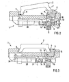
- Figur 2 und 3 einen Schnitt durch den Stativkopf entlang der Linie II/III in Figur 1 mit Anschlußplatte in geöffneter bzw. Schließstellung; und
- Figur 4 eine Draufsicht auf den Stativkopf mit teilweise weggebrochenen Teilen.
- Gemäß Figur 1 bis 3 ist ein um eine horizontale und eine vertikale Achse verschwenkbar, in der eingestellten Schwenk- und Kippposition fixierbarer Stativkopf 1 auf einem nicht-dargestellten Stativ zur Schnellfixierung einer Anschlussplatte 2 ausgebildet, auf der das nicht-dargestellte Gerät, beispielsweise ein Teleskop oder eine Kamera, befestigt ist.
- Der Stativkopf 1 weist an seiner Oberseite auf einer Seite der Anschlußplatte 2 eine Nut 3 und auf der anderen Seite der Anschlußplatte 2 eine zweite Nut 4 auf. Während die Nut 3 starr auf dem Stativkopf 1 ausgebildet ist, ist die Nut 4 an der Innenseite eines Klemmbackens 5 vorgesehen.
- Zum Einstecken in die eine Nut 3 bzw. zum Übergreifen durch die Nut 4 in den Klemmbacken 5 weist die rechteckige Anschlußplatte 2 an den betreffenden, einander gegenüberliegenden Seiten vorzugsweise jeweils einen Fuß 6, 7 auf, der sich an der Außenseite nach unten schräg nach außen erstreckt.
- Der Klemmbacken 5 ist um eine waagrechte, das heißt zur Ebene der Anschlußplatte 2 parallele Achse 8 kippbar an einem Schieber 9 befestigt.
- Der beispielsweise als Leiste ausgebildete Schieber 9 ist im Inneren eines Gehäuses 10 des Stativkopfes 1 verschiebbar geführt. Eine Druckfeder 11 belastet den Schieber 9.
- Der Schieber 9 weist eine Nut oder dergleichen Ausnehmung 13 auf, in die ein zum Beispiel als Leiste ausgebildeter Riegel 14 mit einer Nase oder dergleichen Eingriffsabschnitt 15 eingreift, wenn der Schieber 9 mit der Anschlußplatte 2 soweit bewegt worden ist, daß der Klemmbacken 5 auf den Fuß 7 gekippt ist, um die Anschlußplatte 2 zu verriegeln.
- Zum Kippen des Klemmbacken 5 auf den Fuß 7 ist eine schräge Stützfläche 16 an dem Stativkopf 1 vorgesehen. An der Stützfläche 16 liegt der Klemmbacken 5 mit seiner Außenseite an, wenn der Schieber 9 durch den Druck der zu fixierenden Anschlußplatte 2 bewegt wird.
- Damit der Schieber 9 soweit verschoben wird, daß der Klemmbacken 5 den Fuß 7 festklemmt, weist die Nut oder dergleichen Ausnehmung 13 in dem Schieber zwei parallele Schrägflächen 18, 19 auf, in die der Riegel 14 mit seinem Eingriffsabschnitt 15 mit nahezu parallelen Schrägflächen 21, 22 eingreift.
- Die Schrägflächen 18, 19 und 21, 22 sind vorzugsweise so ausgebildet, daß Selbsthemmung herrscht und damit ein selbsttätiges Öffnen der Schnellfixierung verhindert ist.
- Der in dem Gehäuse 10 des Stativkopfes 1 verschiebbar gelagerte Riegel 14 greift dabei mit seinem Eingriffsabschnitt 15 an der Seite des Schiebers 9 an, die der starren Nut 3 an der Oberseite des Stativkopfes 1 gegenüber liegt. Gemäß Figur 4 wird der Riegel 14 durch zwei Zugfedern 23 in die Verriegelungsstellung belastet.
- Um den Riegel 14 zu betätigen, ist gemäß Figur 4 ein zweiarmiger Hebel 25 in dem Stativkopfgehäuse 10 gelagert, dessen einer Arm einen Bedienungshebel 26 bildet, während der andere, kurze Hebelarm 27 an einer Stange 28 angelenkt ist, die an dem Riegel 14 gelenkig angreift. Die Gelenkachsen 30, 31 der Stange 28 verlaufen parallel zur Hebelachse 32. Wie in Figur 4 gestrichelt dargestellt, ist der Bedienungshebel 26 in der Schließstellung bei verriegeltem Schieber 9 an das Stativkopfgehäuse 10 geklappt.
- An der starren Nut 3 sind an beiden Enden Flanken 33 zur Führung der Anschlußplatte 2 vorgesehen.
Claims (12)
- Stativkopf (1) zur Schnellfixierung an einer an einem Gerät befestigten Anschlussplatte (2), der an der Oberseite eine Nut (3), in die die Anschlussplatte (2) mit einer Seite steckbar ist, und einen Klemmbacken (5) aufweist, welcher die gegenüberliegende Seite der Anschlussplatte (2) in der Schließstellung übergreift, um eine zur Anschlussplattenebene parallele Achse (8) kippbar ist und durch einen federbelasteten Riegel (14) in der Schließstellung verriegelbar ist, der in eine Ausnehmung (13) eingreift, dadurch gekennzeichnet, dass der Klemmbacken (5) an einem Schieber (9) befestigt ist, der durch Druck mit der Anschlussplatte (2) entgegen einer Federkraft verschiebbar ist und der die Ausnehmung (13) aufweist, in die der Riegel (14) eingreift, wobei der Klemmbacken (5) bei Verschiebung des Schiebers (9) in die verriegelte Stellung durch eine Stützfläche (16) am Stativkopf (1) auf die Anschlussplatte (2) kippbar ausgebildet ist.
- Stativkopf nach Anspruch 1, dadurch gekennzeichnet, dass der Schieber (9), bezogen auf die fixierte Anschlussplatte (2), senkrecht zur Anschlussplattenebene verschiebbar ausgebildet ist.
- Stativkopf nach Anspruch 1, dadurch gekennzeichnet, dass der Klemmbacken (5) eine Nut (4) zum Übergreifen der Anschlussplatte aufweist.
- Stativkopf nach einem der vorstehenden Ansprüche, dadurch gekennzeichnet, dass der Schieber (9) eine Schrägfläche (18) aufweist, an der der Riegel (14) beim Verriegeln mit einem Angriffsabschnitt (15) mit einer parallelen schrägen Fläche (21) angreift.
- Stativkopf nach Anspruch 4, dadurch gekennzeichnet, dass der Schieber (9) eine Ausnehmung (13) mit zwei parallelen Schrägflächen (18, 19) aufweist, an denen der Angriffsabschnitt (15) des Riegels (14) mit zwei dazu parallelen schrägen Flächen (21, 22) angreift.
- Stativkopf nach Anspruch 4 oder 5, dadurch gekennzeichnet, dass die Schrägflächen (18, 19, 21, 22) selbsthemmend ausgebildet sind.
- Stativkopf nach einem der vorstehenden Ansprüche, dadurch gekennzeichnet, dass der Angriffsabschnitt (15) des Riegels (14) von der Nut (3) des Stativkopfes (1) gegenüberliegenden Seite an dem Schieber (9) angreift.
- Stativkopf nach Anspruch 7, dadurch gekennzeichnet, dass der Riegel (14) durch wenigstens eine Zugfeder (23) in die Verriegelungsstellung belastet ist.
- Stativkopf nach einem der vorstehenden Ansprüche, dadurch gekennzeichnet, dass der Riegel (14) durch einen Druckknopf oder dergleichen Handhabe entgegen der ihn belastenden Federkraft in seine Außereingriffsstellung bewegbar ist.
- Stativkopf nach Anspruch 9, dadurch gekennzeichnet, dass die Handhabe durch den einen Arm (26) eines zweiarmigen Hebels (25) gebildet wird, dessen zweiter Hebelarm (27) über ein Gestänge (28) an dem Riegel (14) angreift.
- Stativkopf nach Anspruch 10, dadurch gekennzeichnet, dass der als Bedienungshebel (26) ausgebildete eine Hebelarm in der Schließstellung bei verriegeltem Schieber (9) an das Stativkopfgehäuse (10) geklappt ist.
- Stativkopf nach einem der vorstehenden Ansprüche, dadurch gekennzeichnet, dass an der Nut (3), in die die Anschlussplatte (2) steckbar ist, Flanken (33) zur Führung der Anschlussplatte (2) vorgesehen sind.
Priority Applications (4)
| Application Number | Priority Date | Filing Date | Title |
|---|---|---|---|
| AT02011356T ATE356313T1 (de) | 2002-05-23 | 2002-05-23 | Stativkopf |
| DE50209654T DE50209654D1 (de) | 2002-05-23 | 2002-05-23 | Stativkopf |
| EP02011356A EP1365187B1 (de) | 2002-05-23 | 2002-05-23 | Stativkopf |
| US10/429,306 US6827319B2 (en) | 2002-05-23 | 2003-05-05 | Apparatus for quick fixation of a device to a tripod head |
Applications Claiming Priority (1)
| Application Number | Priority Date | Filing Date | Title |
|---|---|---|---|
| EP02011356A EP1365187B1 (de) | 2002-05-23 | 2002-05-23 | Stativkopf |
Publications (2)
| Publication Number | Publication Date |
|---|---|
| EP1365187A1 EP1365187A1 (de) | 2003-11-26 |
| EP1365187B1 true EP1365187B1 (de) | 2007-03-07 |
Family
ID=29286144
Family Applications (1)
| Application Number | Title | Priority Date | Filing Date |
|---|---|---|---|
| EP02011356A Expired - Lifetime EP1365187B1 (de) | 2002-05-23 | 2002-05-23 | Stativkopf |
Country Status (4)
| Country | Link |
|---|---|
| US (1) | US6827319B2 (de) |
| EP (1) | EP1365187B1 (de) |
| AT (1) | ATE356313T1 (de) |
| DE (1) | DE50209654D1 (de) |
Cited By (2)
| Publication number | Priority date | Publication date | Assignee | Title |
|---|---|---|---|---|
| WO2022160542A1 (zh) * | 2021-01-29 | 2022-08-04 | 昆山蒲公英智能科技有限公司 | 一种快速连接机构 |
| EP4431785A1 (de) * | 2023-03-13 | 2024-09-18 | Garrit Keller | Haltesystem und verfahren zur lösbaren befestigung eines flachen gegenstands an einem objekt und haltevorrichtung zur verwendung in einem solchen haltesystem |
Families Citing this family (62)
| Publication number | Priority date | Publication date | Assignee | Title |
|---|---|---|---|---|
| USD596658S1 (en) * | 2001-07-12 | 2009-07-21 | Dordick Scott D | Camera mount |
| US7111424B1 (en) * | 2003-12-02 | 2006-09-26 | Moody Joseph R | Fore grip with bipod |
| US7669357B2 (en) | 2003-12-02 | 2010-03-02 | Grip Pod Systems, Llc | Rotating and canting vertical fore grip with bipod |
| US7490429B2 (en) * | 2003-12-02 | 2009-02-17 | Grip Pod Systems, L.L.C. | Vertical fore grip with bipod |
| US7861451B1 (en) * | 2003-12-02 | 2011-01-04 | Grip Pod Systems, Llc | Folding stack plate for foregrips |
| US8393104B1 (en) | 2003-12-02 | 2013-03-12 | Grip Pod Systems International, Llc | Folding stack improvements |
| US7987623B1 (en) | 2007-11-02 | 2011-08-02 | Grip Pod Systems, Llc | Folding stack improvements |
| US7568304B1 (en) * | 2003-12-02 | 2009-08-04 | Grip Pod System, Llc | Light rail and accessory rail mount for vertical fore grip |
| US8069603B2 (en) | 2003-12-02 | 2011-12-06 | Grip Pod Systems, Llc | Canting vertical fore grip with bipod |
| US8341866B1 (en) | 2003-12-02 | 2013-01-01 | Grip Pod Systems International, Llc | Flip attachment adapters, devices, systems and methods for firearms |
| US7421815B1 (en) | 2003-12-02 | 2008-09-09 | Grip Pod Systems, L.L.C. | Canting vertical fore grip with bipod |
| US7631455B2 (en) * | 2004-02-12 | 2009-12-15 | Da Keng | Quick disconnect bipod mount assembly with adjustable and lockable tilt, pan and cant controls |
| USD525642S1 (en) * | 2004-02-26 | 2006-07-25 | Heiwa Seiki Kogyo | Tripod head for cameras |
| US7658556B2 (en) * | 2005-01-07 | 2010-02-09 | Joseph Johnson | Panoramic camera mount |
| USD532813S1 (en) * | 2005-06-21 | 2006-11-28 | Lino Manfrotto & Co., S.P.A. | Support head for optical and photographic equipments |
| DE102005037782A1 (de) * | 2005-08-10 | 2007-02-22 | Sachtler Gmbh & Co. Kg | Kamerastativkopf |
| US7185862B1 (en) * | 2005-10-04 | 2007-03-06 | Jen Yu Yang | Mounting platform assembly for a stand device |
| USD553662S1 (en) * | 2006-01-12 | 2007-10-23 | Videotec S.P.A. | Swivel for a video camera |
| USD575321S1 (en) * | 2006-02-17 | 2008-08-19 | Vogel's Holding B.V. | Support for a projector |
| CN100460991C (zh) * | 2006-08-22 | 2009-02-11 | 威宝摄影器材有限公司 | 相机与云台快速连接器 |
| USD564567S1 (en) * | 2007-03-23 | 2008-03-18 | Dordick Scott D | Camera mount |
| USD603442S1 (en) * | 2007-03-23 | 2009-11-03 | Scott David Dordick | Camera mount |
| USD564010S1 (en) * | 2007-03-23 | 2008-03-11 | Dordick Scott D | Camera mount |
| DE102007035562A1 (de) | 2007-07-28 | 2009-01-29 | Philippe Vogt | Befestigungsanordnung für optische Geräte |
| DE102007052039B3 (de) * | 2007-10-30 | 2009-06-10 | FLM GMBH FOTO-, LICHT- UND MEßTECHNISCHES ZUBEHÖR | Stativkopf |
| CN101598886B (zh) * | 2009-07-07 | 2010-12-29 | 刘昊 | 四轴摄影云台 |
| DE102009038823B4 (de) | 2009-08-25 | 2012-11-15 | Philippe Vogt | Schnellspanneinrichtung für optische Geräte |
| USD629440S1 (en) * | 2010-02-03 | 2010-12-21 | Head North Incorporated | Camera mount |
| DE202010002724U1 (de) | 2010-02-24 | 2010-07-08 | Vogt, Philippe | L-förmiger Halter für optische Geräte |
| DE102010036405A1 (de) | 2010-07-14 | 2012-01-19 | Philippe Vogt | Stativkopf |
| US8398315B2 (en) * | 2010-11-03 | 2013-03-19 | Joseph M. Johnson | Quick-release apparatus |
| DE102011108594A1 (de) * | 2011-07-26 | 2013-01-31 | Daimler Ag | Befestigungsanordnung eines Sensorelements an einem Befestigungselement eines Kraftwagens |
| US8807496B2 (en) * | 2011-12-09 | 2014-08-19 | Kessler Crane, Inc. | Camera mount |
| US20130175411A1 (en) * | 2012-01-09 | 2013-07-11 | Youngil Kim | Stand adapter for projector or recording device |
| ITPD20120034A1 (it) * | 2012-02-10 | 2013-08-11 | Manfrotto Lino & C Spa | Sistema di attacco per apparecchiature video-fotografiche su una testa di supporto |
| USD706894S1 (en) | 2012-12-21 | 2014-06-10 | Grip Pod Systems International, Llc | Cam lever mount for attaching firearm accessories to picatinny rails on firearms |
| US8806796B1 (en) | 2013-02-22 | 2014-08-19 | Prezine, Llc | Cam lever mount |
| US8727642B1 (en) * | 2013-03-11 | 2014-05-20 | Wilson Tse | Quick-release camera mounting system |
| US9709356B1 (en) * | 2014-05-06 | 2017-07-18 | Tja Design Llc | Multi-axis firearm foregrip |
| KR101722324B1 (ko) * | 2015-08-07 | 2017-04-04 | 이해심 | 멀티 퀵슈 |
| US10168119B2 (en) * | 2016-12-23 | 2019-01-01 | Magpul Industries Corp. | Firearm bipod |
| US10364935B2 (en) * | 2017-10-25 | 2019-07-30 | Lumiquest Ventures Llc | Photographic mount |
| US20190271902A1 (en) * | 2018-03-01 | 2019-09-05 | Really Right Stuff, Llc | Support for a tripod |
| CN110325781A (zh) * | 2018-03-23 | 2019-10-11 | 深圳市大疆创新科技有限公司 | 手柄快拆结构及拍摄设备 |
| US10982806B2 (en) | 2019-05-13 | 2021-04-20 | Peak Design | Close-pack, high-aspect-ratio camera tripod |
| US11320724B2 (en) | 2019-05-13 | 2022-05-03 | Peak Design | Close-pack, high-aspect-ratio camera tripod |
| KR102784821B1 (ko) * | 2019-05-13 | 2025-03-21 | 피크 디자인 | 클로즈-팩, 고종횡비 카메라 삼각대 |
| CN114980602B (zh) | 2019-07-31 | 2024-06-14 | 尖峰设计公司 | 移动设备安装系统 |
| US11548451B2 (en) | 2019-07-31 | 2023-01-10 | Peak Design | Mobile device mounting system |
| CN111895230B (zh) * | 2020-06-23 | 2021-11-16 | 哈尔滨讯达广智能科技发展有限公司 | 一种带热电制冷器的激光器支架 |
| US11211963B1 (en) | 2020-10-15 | 2021-12-28 | Peak Design | Mobile device case system |
| US11722166B2 (en) | 2020-10-15 | 2023-08-08 | Peak Design | Mobile device case system |
| EP4342164A4 (de) | 2021-05-28 | 2025-04-09 | Peak Design | Mobiles tripode-montagesystem |
| DE202021104086U1 (de) * | 2021-07-30 | 2021-08-11 | Arnold & Richter Cine Technik Gmbh & Co. Betriebs Kg | Arretiervorrichtung Kamerahalterung mit Arretiervorrichtung |
| US12359685B2 (en) * | 2021-09-01 | 2025-07-15 | Shadow Tech, LLC | Clamp with cam lever |
| US11752596B2 (en) * | 2021-09-01 | 2023-09-12 | Joshua Stabler | Compressible cam lever |
| US11852179B2 (en) | 2021-11-10 | 2023-12-26 | DQD Mounting Systems, LLC | Quick release mounting system |
| US11852430B1 (en) | 2022-06-16 | 2023-12-26 | DQD Mounting Systems, LLC | Firearm safety device and rack incorporating safety device |
| WO2024038066A1 (en) * | 2022-08-18 | 2024-02-22 | Koninklijke Philips N.V. | Device for fixing defibrillator |
| US20240410515A1 (en) * | 2023-06-09 | 2024-12-12 | Really Right Stuff, Llc | Support for a clamp with improved structure |
| CN118009158A (zh) * | 2024-01-11 | 2024-05-10 | 中山大山摄影器材有限公司 | 快速拆装的摄影器材固定装置 |
| WO2026032496A1 (de) | 2024-08-06 | 2026-02-12 | Fr-Innovations Gmbh | Aufsetzkamera mit lichtquelle und deren forstwirtschaftliche verwendung |
Family Cites Families (13)
| Publication number | Priority date | Publication date | Assignee | Title |
|---|---|---|---|---|
| US2351386A (en) * | 1942-12-23 | 1944-06-13 | Frank C Zucker | Alignment gauge |
| US2482708A (en) * | 1944-06-29 | 1949-09-20 | Special Engineering Service In | Plunger actuated hold-down clamp |
| US2834567A (en) * | 1954-03-30 | 1958-05-13 | James B Young | Camera tripod adapter |
| US3356325A (en) | 1965-10-22 | 1967-12-05 | Davidson Optronics Inc | Camera-to-tripod connector |
| US3429543A (en) * | 1967-03-23 | 1969-02-25 | Quick Set Inc | Instrument mount |
| US3612462A (en) * | 1969-08-26 | 1971-10-12 | Quick Set Inc | Instrument mount assembly |
| US4244547A (en) * | 1978-12-20 | 1981-01-13 | Keuffel & Esser Company | Theodolite leveling means |
| US4466595A (en) * | 1981-06-22 | 1984-08-21 | Oconnor Chadwell | Camera lock-plate assembly |
| FR2552579B1 (fr) * | 1983-09-28 | 1985-12-13 | Pflieger Roger | Dispositif de fixation rapide d'un appareil de prise de vues sur un plateau de trepied |
| DE8716995U1 (de) * | 1987-12-24 | 1988-02-18 | Cullmann Handelsgesellschaft für Verbrauchsgüter mbH, 8506 Langenzenn | Stativkopf |
| JPH0626799Y2 (ja) * | 1989-02-28 | 1994-07-20 | 平和精機工業株式会社 | 雲 台 |
| JPH0544890A (ja) * | 1991-08-09 | 1993-02-23 | Heiwa Seiki Kogyo Kk | 雲 台 |
| US6371424B1 (en) * | 1999-09-10 | 2002-04-16 | General Dynamics Canada Ltd. | Mounting an article upon a support |
-
2002
- 2002-05-23 AT AT02011356T patent/ATE356313T1/de not_active IP Right Cessation
- 2002-05-23 DE DE50209654T patent/DE50209654D1/de not_active Expired - Lifetime
- 2002-05-23 EP EP02011356A patent/EP1365187B1/de not_active Expired - Lifetime
-
2003
- 2003-05-05 US US10/429,306 patent/US6827319B2/en not_active Expired - Lifetime
Cited By (3)
| Publication number | Priority date | Publication date | Assignee | Title |
|---|---|---|---|---|
| WO2022160542A1 (zh) * | 2021-01-29 | 2022-08-04 | 昆山蒲公英智能科技有限公司 | 一种快速连接机构 |
| US11959581B2 (en) | 2021-01-29 | 2024-04-16 | Pgytech Co., Ltd. | Quick connection mechanism |
| EP4431785A1 (de) * | 2023-03-13 | 2024-09-18 | Garrit Keller | Haltesystem und verfahren zur lösbaren befestigung eines flachen gegenstands an einem objekt und haltevorrichtung zur verwendung in einem solchen haltesystem |
Also Published As
| Publication number | Publication date |
|---|---|
| DE50209654D1 (de) | 2007-04-19 |
| US6827319B2 (en) | 2004-12-07 |
| ATE356313T1 (de) | 2007-03-15 |
| EP1365187A1 (de) | 2003-11-26 |
| US20030218108A1 (en) | 2003-11-27 |
Similar Documents
| Publication | Publication Date | Title |
|---|---|---|
| EP1365187A1 (de) | Vorrichtung zur Schnellfixierung eines Gerätes an einem Stativkopf | |
| EP0647545B1 (de) | Querträger für Dachlasten an einem mit einer Dachreling ausgestatteten Kraftwagen | |
| EP0693653B1 (de) | Vorrichtung zum lösbaren Verbinden eines fotografischen oder optischen Gerätes mit einem Stativ oder dergleichen | |
| DE19538988A1 (de) | Tischüberbrückungsvorrichtung | |
| DE3804199C2 (de) | ||
| EP2196720B1 (de) | Schnellspannvorrichtung | |
| DE102004013066B4 (de) | Spann- und Spreizvorrichtung | |
| EP3179199A1 (de) | Vorrichtung zur befestigung eines zusatzteils an einer waffe | |
| EP0152607B2 (de) | Dachlastenträger für Kraftfahrzeuge | |
| EP0684112A1 (de) | Spanntisch | |
| EP1809441A1 (de) | Spann- oder greifvorrichtung insbesondere linear- oder zentrischgreifer | |
| EP1582903A1 (de) | Vorrichtung zum Befestigen eines Mikroskophalters | |
| EP1454872B1 (de) | Transportsicherung | |
| DE4018414C2 (de) | Vorrichtung zum Abstützen und Befestigen von Objektiven, Objektivteilen und/oder Objektivvorsätzen für eine Kamera | |
| DE102022124145A1 (de) | Translations-Rotations-Beschlag und Möbel- oder Haushaltsgeräteelement | |
| DE9111217U1 (de) | Halterung für ein Mobiltelefon | |
| EP0236350A1 (de) | Zwinge | |
| DE9312687U1 (de) | Spanneinrichtung, insbesondere Kniehebelspanner | |
| DE10244277C1 (de) | Vorrichtung zur Einstellung der Beinspreizung eines Holzstativs, insbesondere eines Dreibeinstativs | |
| EP0184776B1 (de) | Tisch | |
| DE9202090U1 (de) | Spannkloben zur Befestigung von Zubehörteilen an Halteprofilen | |
| DE19647837A1 (de) | Montage-Schwenkvorrichtung | |
| DE19725044C2 (de) | Verbindungseinrichtung zum Verbinden zweier Komponenten eines Möbelverbundsystems | |
| DE202018103211U1 (de) | Stützvorrichtung | |
| DE69826785T2 (de) | Arbeitstisch mit schwenkbarem Trägerelement |
Legal Events
| Date | Code | Title | Description |
|---|---|---|---|
| PUAI | Public reference made under article 153(3) epc to a published international application that has entered the european phase |
Free format text: ORIGINAL CODE: 0009012 |
|
| AK | Designated contracting states |
Kind code of ref document: A1 Designated state(s): AT BE CH CY DE DK ES FI FR GB GR IE IT LI LU MC NL PT SE TR |
|
| AX | Request for extension of the european patent |
Extension state: AL LT LV MK RO SI |
|
| 17P | Request for examination filed |
Effective date: 20040406 |
|
| AKX | Designation fees paid |
Designated state(s): AT BE CH CY DE DK ES FI FR GB GR IE IT LI LU MC NL PT SE TR |
|
| GRAP | Despatch of communication of intention to grant a patent |
Free format text: ORIGINAL CODE: EPIDOSNIGR1 |
|
| RTI1 | Title (correction) |
Free format text: SUPPORT HEAD |
|
| GRAS | Grant fee paid |
Free format text: ORIGINAL CODE: EPIDOSNIGR3 |
|
| GRAA | (expected) grant |
Free format text: ORIGINAL CODE: 0009210 |
|
| AK | Designated contracting states |
Kind code of ref document: B1 Designated state(s): AT BE CH CY DE DK ES FI FR GB GR IE IT LI LU MC NL PT SE TR |
|
| PG25 | Lapsed in a contracting state [announced via postgrant information from national office to epo] |
Ref country code: FI Free format text: LAPSE BECAUSE OF FAILURE TO SUBMIT A TRANSLATION OF THE DESCRIPTION OR TO PAY THE FEE WITHIN THE PRESCRIBED TIME-LIMIT Effective date: 20070307 Ref country code: IE Free format text: LAPSE BECAUSE OF FAILURE TO SUBMIT A TRANSLATION OF THE DESCRIPTION OR TO PAY THE FEE WITHIN THE PRESCRIBED TIME-LIMIT Effective date: 20070307 |
|
| REG | Reference to a national code |
Ref country code: GB Ref legal event code: FG4D Free format text: NOT ENGLISH |
|
| REG | Reference to a national code |
Ref country code: CH Ref legal event code: EP |
|
| REF | Corresponds to: |
Ref document number: 50209654 Country of ref document: DE Date of ref document: 20070419 Kind code of ref document: P |
|
| REG | Reference to a national code |
Ref country code: IE Ref legal event code: FG4D Free format text: LANGUAGE OF EP DOCUMENT: GERMAN |
|
| PGFP | Annual fee paid to national office [announced via postgrant information from national office to epo] |
Ref country code: AT Payment date: 20070524 Year of fee payment: 6 |
|
| GBT | Gb: translation of ep patent filed (gb section 77(6)(a)/1977) |
Effective date: 20070515 |
|
| PG25 | Lapsed in a contracting state [announced via postgrant information from national office to epo] |
Ref country code: SE Free format text: LAPSE BECAUSE OF FAILURE TO SUBMIT A TRANSLATION OF THE DESCRIPTION OR TO PAY THE FEE WITHIN THE PRESCRIBED TIME-LIMIT Effective date: 20070607 |
|
| PG25 | Lapsed in a contracting state [announced via postgrant information from national office to epo] |
Ref country code: ES Free format text: LAPSE BECAUSE OF FAILURE TO SUBMIT A TRANSLATION OF THE DESCRIPTION OR TO PAY THE FEE WITHIN THE PRESCRIBED TIME-LIMIT Effective date: 20070618 |
|
| PG25 | Lapsed in a contracting state [announced via postgrant information from national office to epo] |
Ref country code: PT Free format text: LAPSE BECAUSE OF FAILURE TO SUBMIT A TRANSLATION OF THE DESCRIPTION OR TO PAY THE FEE WITHIN THE PRESCRIBED TIME-LIMIT Effective date: 20070807 |
|
| ET | Fr: translation filed | ||
| REG | Reference to a national code |
Ref country code: IE Ref legal event code: FD4D |
|
| PLBE | No opposition filed within time limit |
Free format text: ORIGINAL CODE: 0009261 |
|
| STAA | Information on the status of an ep patent application or granted ep patent |
Free format text: STATUS: NO OPPOSITION FILED WITHIN TIME LIMIT |
|
| REG | Reference to a national code |
Ref country code: CH Ref legal event code: PL |
|
| PG25 | Lapsed in a contracting state [announced via postgrant information from national office to epo] |
Ref country code: MC Free format text: LAPSE BECAUSE OF NON-PAYMENT OF DUE FEES Effective date: 20070531 Ref country code: DK Free format text: LAPSE BECAUSE OF FAILURE TO SUBMIT A TRANSLATION OF THE DESCRIPTION OR TO PAY THE FEE WITHIN THE PRESCRIBED TIME-LIMIT Effective date: 20070307 |
|
| 26N | No opposition filed |
Effective date: 20071210 |
|
| PG25 | Lapsed in a contracting state [announced via postgrant information from national office to epo] |
Ref country code: LI Free format text: LAPSE BECAUSE OF NON-PAYMENT OF DUE FEES Effective date: 20070531 Ref country code: CH Free format text: LAPSE BECAUSE OF NON-PAYMENT OF DUE FEES Effective date: 20070531 |
|
| PG25 | Lapsed in a contracting state [announced via postgrant information from national office to epo] |
Ref country code: GR Free format text: LAPSE BECAUSE OF FAILURE TO SUBMIT A TRANSLATION OF THE DESCRIPTION OR TO PAY THE FEE WITHIN THE PRESCRIBED TIME-LIMIT Effective date: 20070608 |
|
| PGFP | Annual fee paid to national office [announced via postgrant information from national office to epo] |
Ref country code: NL Payment date: 20080523 Year of fee payment: 7 |
|
| PG25 | Lapsed in a contracting state [announced via postgrant information from national office to epo] |
Ref country code: AT Free format text: LAPSE BECAUSE OF NON-PAYMENT OF DUE FEES Effective date: 20080523 |
|
| PG25 | Lapsed in a contracting state [announced via postgrant information from national office to epo] |
Ref country code: CY Free format text: LAPSE BECAUSE OF FAILURE TO SUBMIT A TRANSLATION OF THE DESCRIPTION OR TO PAY THE FEE WITHIN THE PRESCRIBED TIME-LIMIT Effective date: 20070307 |
|
| PG25 | Lapsed in a contracting state [announced via postgrant information from national office to epo] |
Ref country code: LU Free format text: LAPSE BECAUSE OF NON-PAYMENT OF DUE FEES Effective date: 20070523 |
|
| PGFP | Annual fee paid to national office [announced via postgrant information from national office to epo] |
Ref country code: FR Payment date: 20090519 Year of fee payment: 8 |
|
| PG25 | Lapsed in a contracting state [announced via postgrant information from national office to epo] |
Ref country code: TR Free format text: LAPSE BECAUSE OF FAILURE TO SUBMIT A TRANSLATION OF THE DESCRIPTION OR TO PAY THE FEE WITHIN THE PRESCRIBED TIME-LIMIT Effective date: 20070307 |
|
| NLV4 | Nl: lapsed or anulled due to non-payment of the annual fee |
Effective date: 20091201 |
|
| PG25 | Lapsed in a contracting state [announced via postgrant information from national office to epo] |
Ref country code: NL Free format text: LAPSE BECAUSE OF NON-PAYMENT OF DUE FEES Effective date: 20091201 |
|
| REG | Reference to a national code |
Ref country code: FR Ref legal event code: ST Effective date: 20110131 |
|
| PG25 | Lapsed in a contracting state [announced via postgrant information from national office to epo] |
Ref country code: FR Free format text: LAPSE BECAUSE OF NON-PAYMENT OF DUE FEES Effective date: 20100531 |
|
| PGFP | Annual fee paid to national office [announced via postgrant information from national office to epo] |
Ref country code: BE Payment date: 20120522 Year of fee payment: 11 |
|
| BERE | Be: lapsed |
Owner name: SWAROVSKI OPTIK KG Effective date: 20130531 |
|
| PG25 | Lapsed in a contracting state [announced via postgrant information from national office to epo] |
Ref country code: BE Free format text: LAPSE BECAUSE OF NON-PAYMENT OF DUE FEES Effective date: 20130531 |
|
| PGFP | Annual fee paid to national office [announced via postgrant information from national office to epo] |
Ref country code: IT Payment date: 20140526 Year of fee payment: 13 |
|
| PG25 | Lapsed in a contracting state [announced via postgrant information from national office to epo] |
Ref country code: IT Free format text: LAPSE BECAUSE OF NON-PAYMENT OF DUE FEES Effective date: 20150523 |
|
| PGFP | Annual fee paid to national office [announced via postgrant information from national office to epo] |
Ref country code: GB Payment date: 20160523 Year of fee payment: 15 |
|
| PGFP | Annual fee paid to national office [announced via postgrant information from national office to epo] |
Ref country code: DE Payment date: 20170621 Year of fee payment: 16 |
|
| GBPC | Gb: european patent ceased through non-payment of renewal fee |
Effective date: 20170523 |
|
| PG25 | Lapsed in a contracting state [announced via postgrant information from national office to epo] |
Ref country code: GB Free format text: LAPSE BECAUSE OF NON-PAYMENT OF DUE FEES Effective date: 20170523 |
|
| REG | Reference to a national code |
Ref country code: DE Ref legal event code: R119 Ref document number: 50209654 Country of ref document: DE |
|
| PG25 | Lapsed in a contracting state [announced via postgrant information from national office to epo] |
Ref country code: DE Free format text: LAPSE BECAUSE OF NON-PAYMENT OF DUE FEES Effective date: 20181201 |