EP1364813A1 - Tire pneumatic pressure detector - Google Patents
Tire pneumatic pressure detector Download PDFInfo
- Publication number
- EP1364813A1 EP1364813A1 EP02711327A EP02711327A EP1364813A1 EP 1364813 A1 EP1364813 A1 EP 1364813A1 EP 02711327 A EP02711327 A EP 02711327A EP 02711327 A EP02711327 A EP 02711327A EP 1364813 A1 EP1364813 A1 EP 1364813A1
- Authority
- EP
- European Patent Office
- Prior art keywords
- status value
- wheel speed
- slip
- rotational
- air pressure
- Prior art date
- Legal status (The legal status is an assumption and is not a legal conclusion. Google has not performed a legal analysis and makes no representation as to the accuracy of the status listed.)
- Withdrawn
Links
Images










Classifications
-
- B—PERFORMING OPERATIONS; TRANSPORTING
- B60—VEHICLES IN GENERAL
- B60C—VEHICLE TYRES; TYRE INFLATION; TYRE CHANGING; CONNECTING VALVES TO INFLATABLE ELASTIC BODIES IN GENERAL; DEVICES OR ARRANGEMENTS RELATED TO TYRES
- B60C23/00—Devices for measuring, signalling, controlling, or distributing tyre pressure or temperature, specially adapted for mounting on vehicles; Arrangement of tyre inflating devices on vehicles, e.g. of pumps or of tanks; Tyre cooling arrangements
- B60C23/06—Signalling devices actuated by deformation of the tyre, e.g. tyre mounted deformation sensors or indirect determination of tyre deformation based on wheel speed, wheel-centre to ground distance or inclination of wheel axle
-
- B—PERFORMING OPERATIONS; TRANSPORTING
- B60—VEHICLES IN GENERAL
- B60C—VEHICLE TYRES; TYRE INFLATION; TYRE CHANGING; CONNECTING VALVES TO INFLATABLE ELASTIC BODIES IN GENERAL; DEVICES OR ARRANGEMENTS RELATED TO TYRES
- B60C23/00—Devices for measuring, signalling, controlling, or distributing tyre pressure or temperature, specially adapted for mounting on vehicles; Arrangement of tyre inflating devices on vehicles, e.g. of pumps or of tanks; Tyre cooling arrangements
- B60C23/06—Signalling devices actuated by deformation of the tyre, e.g. tyre mounted deformation sensors or indirect determination of tyre deformation based on wheel speed, wheel-centre to ground distance or inclination of wheel axle
- B60C23/061—Signalling devices actuated by deformation of the tyre, e.g. tyre mounted deformation sensors or indirect determination of tyre deformation based on wheel speed, wheel-centre to ground distance or inclination of wheel axle by monitoring wheel speed
Definitions
- the present invention relates to a device for detecting a tire air pressure based on a vehicle speed signal.
- JP-A-H10-100624 discloses a conventional tire air pressure detection device.
- the tire air pressure device detects a decrease in tire air pressure based on wheel speed variation D and a front and rear wheel speed ratio ⁇ .
- the wheel speed variation D and the front and rear wheel speed ratio ⁇ are expressed as follows, where V FR corresponds to front right wheel speed, V FL corresponds front left wheel speed, V RR corresponds rear right wheel speed and V RL corresponds rear left wheel speed.
- the wheel speed variation D represents a rotational status value calculated based on wheel speeds of four vehicle wheels.
- the wheel speed variation D is a variable defined as a difference of wheel speed ratios of each pair of wheels located diagonally from each other, and increases or decreases when the tire air pressure of some of the vehicle wheels decrease.
- the front and rear wheel speed ratio ⁇ is a tire slip status value that denotes a degree of slip status of driven wheels caused by transmitted driving forces. For example, the smaller the front and rear wheel speed ratio ⁇ is, the higher the slip of one (or both) of the driven wheels is.
- the wheel speed variation D increases or decreases when the tire air pressures of some of the vehicle wheels decreases below a standard value, and it is zero when each tire air pressure of each tire equals the standard value. Therefore, the tire pressure decrease is detected based on the wheel speed variation D.
- the wheel speed variation D varies based on the degree of slip status of the wheels.
- a regression line is calculated based on a relationship of the front and rear wheel speed ratio ⁇ and the wheel speed variation D using a minimum square calculation methodology.
- An ideal value of the wheel speed variation D is then calculated by compensating for the wheel speed variation D (or an average D AVE ).
- An ideal value of the wheel speed variation D is a value of the wheel speed variation D if the slip does not occur when the front and rear wheel speed ratio ⁇ is 1.
- the ideal wheel speed variation value D is calculated under the condition that the front and rear wheel speed ratio ⁇ is 1. However, the front and rear wheel speed ratio ⁇ is not 1 when the tire air pressure decreases. Therefore, the above compensation is excessive. In this case, changes of the wheel speed variation D of the driven wheels and non-driven wheels due to the tire air pressure decrease are different, and a warning pressure, which is a pressure at which a driver is warned, varies.
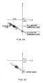
- the tire air pressure decrease is detected under the assumption that the driving force of the wheels usually varies. Therefore, if a variation of the driving force of the wheels decreases when the vehicle is driven on a flat road at a constant speed, values of the front and rear wheel speed ratio ⁇ and the wheel speed variation D do not vary. Referring to FIG. 27, when the accuracy of the calculation of the regression line decreases because of, for example, a small noise caused by a slight turning of the vehicle, the compensation of the wheel speed variation D may not be executed appropriately. As a result, the accuracy of tire air pressure detection decreases.
- the wheel speed variation D corresponding to the rotational status value relates to not only the front and rear wheel speed ratio ⁇ but also to non-uniform wheel rotation when the vehicle is driving (e.g., the non-uniform wheel rotation is caused by turning, driving on a bad road or shift shock of a transmission), varies based on the non-uniform wheel rotation and is non-uniform value.
- the regression line is calculated based on the non-uniform value, the accuracy of the calculation of the wheel speed variation D decreases and therefore the warning pressure varies.
- the wheel speed variation D varies based on the turn status of the vehicle as well as the slip status of the driven wheels.
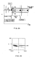
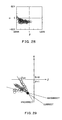
- the relationship of the front and rear wheel speed ratio ⁇ and the wheel speed variation D during turning is plotted in FIG. 28.
- the plotted results are non-uniform as compared with FIG. 26, which does not include data during turning. Therefore, if the regression line is calculated based on all plotted results, it is impossible to calculate an accurate regression line as shown in FIG. 29. As a result, the accuracy of the calculation of the wheel speed variation D decreases, and therefore the warning pressure varies.
- a tire air pressure detection device includes a vehicle wheel speed detecting portion (2a-2d, 3a) for detecting respective vehicle wheel speeds; a rotational status value calculating portion (3b) for calculating a rotational value (D) expressing a relationship of the respective vehicle wheel speeds to cancel a wheel speed variation between left and right wheels generated due to vehicle turns; a slip status value calculating portion (3c) for calculating a slip status value ( ⁇ ) based on the vehicle wheel speeds detected by the vehicle wheel speed detecting portion, the slip status value depending on a slip status between driven wheels and non-driven wheels; a regression line calculating portion (3d) for calculating a regression line that is a linear function expressing a relationship between the rotational status value calculated by the rotational status value calculating portion and the slip status value calculated by the slip status value calculating portion; an ideal driving status calculating portion (3e) for calculating an ideal status value ( ⁇ id)corresponding to a slip value under an ideal driving status without tire slippage; a rotational status value compensating portion (3f)
- the ideal driving status calculating portion calculates the ideal slip status value ( ⁇ id) corresponding to a slip status value under the ideal driving status without tire slip.
- the rotational status value compensating portion calculates the ideal rotational status value based on the regression line calculated by the regression line calculating portion and the ideal slip status value.
- an accurate rotational status value under the ideal driving status without tire slip can be appropriately calculated without excessive compensation when a tire air pressure of driven wheels decreases.
- the rotational status value compensating portion calculates the ideal rotational status value by assuming a rotational status value if the slip status value is the ideal status value based on the regression line calculated by the regression line calculating portion.
- the tire air pressure detection device further includes a rotational status value averaging portion (3b) for calculating a rotational status value average (D AVE ) of the rotational status value calculated by the rotational status value calculating portion; and a slip status value averaging portion (3c) for calculating a slip status value average ( ⁇ AVE of the slip status value calculated by the slip status value calculating portion.
- the rotational status value compensating portion calculates the ideal rotational status value by compensating for the rotational status value average calculated by the rotational status value averaging portion and the slip status value average calculated by the slip status value averaging portion based on the regression line calculated by the regression line calculating portion.
- the slip status value average and the rotational status value average can be compensated for based on the regression line.
- a wheel speed variation (D) corresponding to a difference in wheel speed ratios of each pair of wheels located diagonally from each other may be adopted as the rotational status value.
- a front and rear wheel speed ratio ( ⁇ ) corresponding to a ratio of vehicle wheel speeds of front wheels and vehicle wheel speeds of rear wheels may be adopted as the slip status value.
- the regression line calculating portion calculates a change value (A) of the wheel speed variation with respect to the front and rear wheel speed ratio.
- the ideal driving status value calculating portion calculates one of a linear function and a quadratic function of the change value of the wheel speed variation with respect to the front and rear wheel speed ratio, and also calculates the ideal status value based on calculated function of the change value.
- a tire air pressure detection device includes a selecting portion.
- the selecting portion selects a rotational status value calculated by a rotational status value calculating portion and a slip status value calculated by a slip status value calculating portion within a predetermined available range.
- a regression line calculating portion calculates a regression line based on the rotational status value and the slip status value selected by the selecting portion.
- the tire air pressure detection device has the selecting portion for selecting the rotational status value calculated by the rotational status value calculating portion and the slip status value calculated by the slip status value calculating portion within the predetermined available range.
- the calculation of the regression line by the regression line calculating portion is carried out based on the rotational status value and the slip status value within the predetermined available range selected by the selecting portion. Therefore, the accuracy of the calculation of the regression line does not decrease due to non-uniform of the rotational status value, and therefore a warning pressure is uniform.
- a tire air pressure detection device includes a regression line determining portion for determining whether the regression line is calculated by the regression line calculating portion.
- the selecting portion does not execute a selection when the regression line determining portion has determined that the regression line is not yet calculated, and executes the selection when the regression line determining portion has determined that the regression line has already been calculated.
- the selection by the selecting portion can be executed after a first regression line is calculated.
- the selecting portion may define the predetermined available range based on the regression line calculated by the regression line calculating portion before the selection is not yet executed. For example, according to claim 11, the selecting portion defines a region that includes the regression line and regions having predetermined width on both sides of the regression line as the available range. Accordingly, the variation of the rotational status value caused by vehicle turns is inhibited.
- a tire air pressure detection device includes a driven wheel determining portion for determining whether a wheel in which tire air pressure decreases is a driven wheel.
- the selecting portion defines at least one of higher and lower thresholds as the available range when the driven wheel determining portion determines that the wheel in which the tire air pressure decreases is the driven wheel.
- the higher threshold as the available range prevents the rotational status value from varying caused by temporary tire slippage. Further, the lower threshold as the available range prevents the rotational status value from varying caused by shift shock of a transmission.
- the rotational status value compensating portion calculates an ideal rotational status value when there is no tire slippage based on the regression line calculated by the regression line calculating portion and the ideal slip status value calculated by the ideal driving status calculating portion.
- the tire air pressure detection device calculates the ideal rotational status value based on the regression line and the ideal driving status. Therefore, the tire air pressure detection device can accurately detect a tire air pressure decrease using the ideal rotation status value.
- a tire air pressure detection device includes a driven wheel determining portion for determining whether a wheel in which a tire air pressure decreases is a driven wheel.
- the selecting portion defines a region in which the slip status value is lower than the regression line as the available range when the driven wheel determining portion has determined that the wheel in which the tire air pressure decreases is the driven wheel.
- the available range inhibits the variation of the rotational status value due to a noise caused by deceleration.
- the driven wheel determining portion determines whether the wheel in which the tire air pressure decreases is the driven wheel based on a slope of the regression line calculated by the regression line calculating portion. In detail, according to claim 16, the driven wheel determining portion determines that the wheel in which the tire air pressure decreases is the driven wheel when the slope of the regression line is larger than a predetermined threshold (K).
- a tire air pressure detection device includes a non-uniformity detecting portion (3i) that detects the non-uniform of wheel driving forces.
- the rotational status value compensating portion compensates for the rotational value based on a present regression line calculated by the regression line calculating portion when the non-uniform detecting portion has detected the non-uniformity of the driven forces, while compensating for the rotational value based on a prior regression line calculated by the regression line calculating portion when the non-uniform detecting portion has not detected the non-uniformity of the driven forces.
- the rotational value is compensated for based on a present regression line calculated by the regression line calculating portion when the non-uniformity of the driven forces is generated.
- the rotational value is compensated for based on a prior regression line calculated by the regression line calculating portion when the non-uniformity of the driven forces is not generated. Therefore, even if the wheel driven force non-uniformity does not occur, a small noise caused by a slight vehicle turn does not diminish the accuracy of the calculation of a regression line.
- the tire air pressure detection device can accurately detect a tire air pressure decrease.
- the non-uniformity of the driven forces is detected based on non-uniformity of the slip status value calculated by the slip status value calculating portion.
- the non-uniformity of the driven forces based on non-uniform of the front and rear wheel speed ratio ( ⁇ ) corresponding to a ratio of vehicle wheel speeds of front wheels and vehicle wheel speeds of rear wheels.
- the tire air pressure detection device can be provided with a front and rear wheel speed ratio memorizing portion (3c) for memorizing the front and rear wheel speed ratio calculated by the slip status value calculating portion.
- the non-uniform of the driven forces can be detected based on a difference (Ep) between a maximum value and a minimum value of the front and rear wheel speed ratio.
- the non-uniform of the driven forces can be detected when the difference between the maximum value and the minimum value of the front and rear wheel speed ratio is larger than a first reference value (Ep*+Eth).
- the non-uniform detecting portion defines a second reference value (Eth') larger than the first reference value when the slip variation is not renewed for a predetermined time (Cth), and detects the non-uniform of the driven forces when the difference between the maximum value and the minimum value of the front and rear wheel speed ratio is larger than the second reference value.
- the regression line calculating portion calculates a change value (A) of the wheel speed variation with respect to the front and rear wheel speed ratio.
- the rotational status value compensating portion compensates for the rotational status value calculated by the rotational status value calculating portion based on the slip variation.
- the rotational status value is compensated for based on the slip variation.
- the tire air pressure detection device includes a slip variation memorizing portion for memorizing the slip variation calculated by the regression line calculating portion.
- the slip variation memorizing portion renews a previously calculated slip variation to a presently calculated slip variation when the non-uniform of the driven forces detected by the non-uniform detecting portion is larger than a first reference value (Ep*+Eth).
- the rotational status value compensating portion compensates for the rotational status value calculated by the rotational status value calculating portion based on the slip variation memorized in the slip variation memorizing portion.
- the rotational status value compensating portion calculates an ideal rotational status value when there is no tire slippage based on the regression line calculated by the regression line calculating portion and the ideal slip status value calculated by the ideal driving status calculating portion.
- the tire air pressure detection device calculates the ideal rotational status value based on the regression line and the ideal driving status. Therefore, the tire air pressure detection device can accurately detect a tire air pressure decrease using the ideal rotation status value.
- a tire air pressure detection device includes a selecting portion (3j) for selecting data from data regarding the wheel speeds detected by the wheel speed detecting portion by removing data when the vehicle turns based on left and right non-driven wheels speeds (V FL , V FR ).
- the rotational status value calculating portion calculates the rotational status value and the slip status value calculating portion calculates the slip status value based on the data selected by the selecting portion.
- the selecting portion selects data regarding the wheel speeds detected by the wheel speed detecting portion to remove data when the vehicle turns.
- the rotational status value and the slip status value are then calculated based on selected data. Accordingly, the accuracy of the calculation of the regression line does not decrease due to non-uniform of the rotational status value caused by the vehicle turns, and therefore a warning pressure is uniform.
- the selecting portion can include a left and right non-driven wheel speed ratio calculating portion for calculating a left and right non-driven wheel speed ratio (R) based on data of left and right non-driven wheel speeds detected by the wheel speed detecting portion.
- the selecting portion defines an available range based on the left and right non-driven wheel speed ratio calculated by the left and right non-driven wheel speed ratio calculating portion, and selects the data based on whether the left and right non-driven wheel speed ratio is in the available range.
- a tire air pressure detection device includes a selecting portion for defining an available range based on data regarding left and right non-driven wheel speeds included in the wheel speeds detected by the wheel speed detecting portion, and selecting data within the available range from the data regarding left and right non-driven wheel speeds.
- the rotational status value calculating portion calculates the rotational status value and the slip status value calculating portion calculates the slip status value based on the data selected by the selecting portion.
- the available range is defined initially based on the data regarding left and right non-driven wheel speeds, and is then repeatedly renewed each time the selecting portion selects the data regarding left and right non-driven wheel speeds.
- a tire air pressure detection device includes a left and right non-driven wheel speed ratio calculating portion for calculating a left and right non-driven wheel speed ratio (R) based on data of left and right non-driven wheel speeds (V FL , V FR ) detected by the wheel speed detecting portion, and a left and right non-driven wheel speed ratio determining portion for defining an available range based on the left and right non-driven wheel speed ratio calculated by the left and right non-driven wheel speed ratio calculating portion, and determining whether the left and right non-driven wheel speed ratio is in the available range.
- the left and right non-driven wheel speed ratio determining portion selects the data within the available range from data regarding the wheel speed detected by the wheel speed detecting portion.
- the rotational status value calculating portion calculates the rotational status value and the slip status value calculating portion calculates the slip status value based on the data selected by the left and right non-driven wheel speed ratio determining portion.
- the left and right non-driven wheel speed ratio determining portion can define the available range based on an average value (R AVE ) of the left and right non-driven wheel speed ratio calculated by the left and right non-driven wheel speed ratio calculating portion.
- the left and right non-driven wheel speed ratio determining portion defines a region (R AVE - Rw ⁇ R ⁇ R AVE + Rw) defined from a first value corresponding to average value minus a predetermined value (Rw) to a second value corresponding to average value plus the predetermined value as the available value.
- a tire air pressure detection device is for detecting a decrease in tire air pressure of one of the vehicle wheels and is for warning a driver.
- the tire air pressure detection device is applicable to both front or rear wheel drive vehicles. However, in the present embodiment, the tire air pressure detection device will be described with reference to a rear wheel drive vehicle.
- the tire air pressure detection device includes vehicle wheel speed sensors 2a, 2b, 2c and 2d, which are located around respective vehicle wheels 1a, 1b, 1c and 1d, a central processing unit (CPU) 3 and a warning device 4.
- the CPU 3 receives input signals from the vehicle wheel speed sensors 2a-2d and determines whether tire air pressure in one or more of the vehicle wheels 1a-1d decreases to output a warning signal to the warning device 4.
- the vehicle speed sensors 2a-2d correspond vehicle speed detecting portions.
- the vehicle wheel speed sensors 2a, 2b respectively detect and output wheel speed signals of respective non-driven wheels (i.e., left and right front wheels).
- the vehicle wheel speed sensors 2c, 2d detect and output wheel speed signals of respective driven wheels (i.e., left and right rear wheels).
- the CPU 3 is a microcomputer or the like and calculates respective values based on detected signals from the vehicle wheel speed sensors 2a-2d.
- the CPU 3 is constructed as follows.
- the CPU 3 includes a vehicle wheel speed calculation portion 3a and a vehicle wheel speed variation processing portion 3b.
- the vehicle wheel speed calculation portion 3a calculates respective vehicle wheel speeds of respective wheels 1a-1d based on detected signals (e.g., pulse signals) from the vehicle wheel speed sensors 2a-2d.
- the vehicle wheel speed variation processing portion 3b includes a vehicle speed variation calculating portion corresponding to a rotation status value calculating portion, a first vehicle speed variation memorizing portion, and a vehicle speed variation average processing portion. Results calculated by the vehicle wheel speed variation processing portion 3b are used for processing regarding a relative vehicle speed variation D.
- the wheel speed calculating portion 3a calculates the respective vehicle wheel speeds of the respective wheels 1a-1d based on detected signals from the vehicle wheel speed sensors 2a-2d. For example, respective vehicle wheel speeds V FL , V FR , V RL and V RR are calculated based on signals from the vehicle wheel speed sensors 2a-2d inputted over several seconds.
- the vehicle wheel speed variation calculating portion then calculates a wheel speed variation D using the above-mentioned equation (1) based on data corresponding to calculated vehicle wheel speeds.
- the resultant data of the wheel speed variation D is stored in a memory included in the first wheel speed variation memorizing portion.
- the wheel speed variation average processing portion calculates an average value D AVE of the wheel speed variations D based on the resultant data of the wheel speed variation D.
- the average value D AVE of the wheel speed variation D corresponds to the average of n 0 portions of the wheel speed variation D expressed as the following equation.
- D AVE 1 n 0 SD(N)
- the CPU 3 includes a front and rear wheel speed ratio processing portion 3c.
- the front and rear wheel speed ratio processing portion 3c includes a front and rear wheel speed ratio calculating portion corresponding to a slip status value calculating portion, a front and rear wheel speed ratio memorizing portion, and a front and rear wheel speed ratio average processing portion.
- the front and rear wheel speed ratio calculating portion calculates a front and rear wheel speed ratio ⁇ using the above-mentioned equation (2) based on data from the wheel speed calculating portion 3a.
- the resultant data of the front and rear wheel speed ratio ⁇ is stored in a memory included in the front and rear wheel speed ratio memorizing portion.
- the front and rear wheel speed ratio average processing portion calculates the average value ⁇ AVE of the front and rear wheel speed ratios ⁇ based on the resultant data of the front and rear wheel speed ratio ⁇ .
- the CPU 3 also includes a slip variation calculating portion 3d, an ideal driving status value calculating portion 3e, and a wheel speed variation compensating processing portion 3f.
- the slip variation calculation portion 3d calculates slip variation A based on the wheel speed variation D calculated by the wheel speed variation calculating portion of the wheel speed variation processing portion 3b, and the front and rear wheel speed ratio ⁇ calculated by the front and rear wheel speed ratio calculating portion of the front and rear wheel speed ratio processing portion 3c.
- the slip variation A corresponds to the change in value ( ⁇ D/ ⁇ ) of the wheel speed variation D with respect to the front and rear wheel speed ratio ⁇ and is calculated by a minimum square calculation methodology using n 0 portions of the wheel speed variation D and the front and rear wheel speed ratio ⁇ .
- the slip variation calculating portion 3d corresponds to a regression line calculating portion.
- the ideal driving status value calculating portion 3e calculates an ideal driving status value ⁇ id based on calculation results of the slip variation calculating portion 3d.
- the wheel speed variation compensating processing portion 3f includes a wheel speed variation compensating portion and a second wheel speed variation memorizing portion.
- the wheel speed variation compensating portion corresponds to a rotational status value compensating portion.
- the wheel speed variation compensating portion calculates a post-compensation wheel speed variation D' AVE based on the average value D AVE of the wheel speed variation D for each wheel, the average value ⁇ AVE of the front and rear wheel speed ratios ⁇ , the slip variation A, and the ideal driving status value ⁇ id.
- the second wheel speed variation memorizing portion selects and memorizes reference value D' AVE std based on the post-compensation wheel speed variation D' AVE .
- the reference value D' AVE std corresponds to post-compensation wheel speed variation D' AVE when tire air pressures of four wheels are identical to be used for a reference value in determining tire air pressure decrease.
- the reference value D' AVE std is calculated based on the average value D AVE of the wheel speed variation D for each wheel, the average value ⁇ AVE of the front and rear wheel speed ratios ⁇ , the slip variation A, and the ideal driving status value ⁇ id calculated based on the wheel speed variation D and the front and rear wheel speed ratio ⁇ calculated immediately after the CPU 3 starts.
- the CPU 3 further includes a pressure differential threshold calculating portion 3g and a tire air pressure decrease determination portion 3h.
- the pressure differential threshold calculating portion 3g calculates a pressure difference determination value ⁇ D' AVE based on the reference value D' AVE std memorized in the second wheel speed variation memorizing portion and the post-compensation wheel speed variation D' AVE calculated by the wheel speed variation compensating portion.
- the tire air pressure decrease determination portion 3h compares an absolute value
- the warning device 4 warns a vehicle driver of the tire air pressure decrease by causing a warning light equipped in a vehicle passenger compartment to blink.
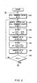
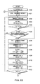
- the wheel speed calculating portion 3a calculates respective vehicle wheel speeds V FL , V FR V RL and V RR .
- the CPU 3 then increases the wheel speed calculation number N.
- the processing calculates respective wheel speed averages of each wheel few several minutes based on the wheel speed pulse generated during those few minutes.
- the wheel speed variation calculating portion of the vehicle wheel speed processing portion 3b calculates the wheel speed variation D.
- the wheel speed variation D is calculated by substituting the respective vehicle wheel speeds V FL , V FR , V RL and V RR calculated at 101 into equation (1).
- the first wheel speed variation memorizing portion memorizes the wheel speed variation D calculated at 102 to add memorized wheel speed variations D(N).
- D(N) corresponds to a stored arrangement of n 0 portions of the wheel speed variation D in a position of the memory corresponding to a number of calculations.
- the first wheel speed variation memorizing portion re-stores a new wheel speed variation D in the position of the memory corresponding to wheel speed calculation number N when, for example, the wheel speed calculation number N is reset at 100 after the n 0 portions of the wheel speed variations D are memorized.
- the front wheel speed ratio calculating portion of the front wheel speed ratio processing portion 3c calculates a front and rear wheel speed ratio ⁇ .
- the front and rear wheel speed ratio ⁇ is also calculated by substituting the respective vehicle wheel speeds V FL , V FR , V RL and V RR calculated at 101 into equation (2).
- the memory of the front and rear wheel speed ratio memorizing portion memorizes the front and rear wheel speed ratio ⁇ calculated at 104 to add memorized front and rear wheel speed ratios ⁇ (N).
- ⁇ (N) corresponds to an arrangement of n 0 memorized portions of the front and rear wheel speed ratio ⁇ stored in a position of the memory corresponding to the number of calculations.
- the front and rear wheel speed ratio memorizing portion re-stores a new front and rear wheel speed ratio ⁇ in the position of the memory corresponding to wheel speed calculation number N as well as the D(N) after the n 0 portions of the front and rear wheel speed ratios ⁇ are memorized.
- the CPU 3 determines whether the wheel speed calculation number N is larger than n 0 .
- the processing advances to 107 when a determination at 106 is positive because n 0 portions of the wheel speed variation D of each wheel and the front and rear wheel speed ratios ⁇ are memorized, and returns at 101 when the determination at 106 is negative.
- the slip calculating portion 3d calculates a slip variation A. That is, a regression line corresponding to a linear function of the wheel speed variation D and the front and rear wheel speed ratio ⁇ is calculated, and the slip variation A is calculated based on the regression line.
- the slip variation A expresses a dependent degree of the wheel speed variation D with respect to the front and rear wheel speed ratio ⁇ .
- the wheel speed variation averaging portion of the wheel speed variation processing portion 3b calculates an average value D AVE of the wheel speed variation D of each wheel.
- the average value D AVE of the wheel speed variations D is calculated by substituting respective wheel speed variations D memorized at 103 into equation (3).
- the front and rear wheel speed ratio averaging processing portion of the front and rear wheel speed ratio processing portion 3c calculates an average value ⁇ AVE of the front and rear wheel speed ratios ⁇ stored in the memory.
- the average of the front and rear wheel speed ratios ⁇ is calculated by substituting respective front and rear wheel speed ratios ⁇ memorized at 105 into equation (4).
- the ideal driving status value calculating portion 3e calculates an ideal driving status value ⁇ id.
- the ideal driving status value ⁇ id is calculated based on the linear function, quadratic function or the like of the slip variation A calculated at 110.
- the wheel speed variation compensating portion of the wheel speed variation compensating processing portion 3f calculates a post-compensation wheel speed variation D' AVE by substituting the average value D AVE , the average value ⁇ AVE , the slip variation A, and the ideal driving status value ⁇ id calculated at 107-110 respectively into equation (5).
- the CPU 3 determines whether the reference value D' AVE std has already been determined.
- the processing determines whether the reference value D' AVE std is stored in the memory of the second wheel speed variation memorizing portion of the wheel speed variation compensating processing portion 3f. If the reference value D' AVE std is calculated at first after the CPU 3 starts, the processing advances to 113 to store the post-compensation wheel speed variation D' AVE calculated as a reference value D' AVE std and then returns to 100. On the other hand, if the reference value D' AVE std has already been stored, the processing advances to 114.
- the pressure difference threshold calculating portion 3g calculates a pressure difference determination value ⁇ D' AVE that corresponds to a difference between the reference value D' AVE std and the post-compensation wheel speed variation D' AVE .
- the tire air pressure decrease determination portion 3h determines whether an absolute value
- the processing advances to 116 when a determination is positive.
- the tire air pressure decrease determination portion 3h transmits a warning signal denoting tire air pressure decrease to the warning device 4.
- the processing returns at 100 when the determination is negative.
- the tire air pressure decrease of respective wheels 1a-1d can be detected.
- the slip variation A is calculated based on a wheel speed variation D and a front and rear wheel speed ratio ⁇ .
- An ideal driving status value ⁇ id is then calculated based on the slip variation A.
- a post-compensation wheel speed variation D' AVE is calculated based on an average value D AVE of the wheel speed variation D of each wheel, an average value ⁇ AVE of the front and rear wheel speed ratios ⁇ , the slip variation A, and the ideal driving status value ⁇ id.
- FIG. 4 shows a relationship between the wheel speed variation D and the front and rear wheel speed ratio ⁇ when a tire air pressure of one of the driven wheels 1c 1d (e.g., the left rear wheel) decreases.
- white circles ( ⁇ ) indicate n0 portions of the relationship between the wheel speed variation D and the front and rear wheel speed ratio ⁇
- black circles ( ⁇ ) indicate a relationship between the average value D AVE of the wheel speed variations D and the average value ⁇ AVE of the front and rear wheel speed ratios ⁇ .
- a regression line corresponding to a linear function of n 0 portions of the wheel speed variation D and the front and rear wheel speed ratio ⁇ is calculated using a minimum square calculation methodology.
- a post-compensation wheel speed variation D' AVE which corresponds to a wheel speed variation D under ideal driving status when a tire air pressure of at least one of the driven wheels 1c, 1d decreases, is calculated.
- the post-compensation wheel speed variation D' AVE can be appropriately calculated without excessive compensation.
- a post-compensation wheel speed variation change ratio when a tire air pressure of a driven wheel decreases is different from that when a tire air pressure of a non-driven wheel decreases.
- the post-compensation wheel speed variation when the tire air pressure of the driven wheel decreases is calculated as having a value smaller than that when the tire air pressure of the non-driven wheel decreases.
- the post-compensation wheel speed variation D' AVE when the tire air pressure of the driven wheel decreases and that when the tire air pressure of the non-driven wheel decreases are identical. Therefore, regardless of which wheels decrease in pressure, a warning pressure remains uniform.
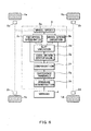
- a tire air pressure detection device has a different construction from that of the first embodiment. As shown in FIG. 6, in this embodiment, the tire air pressure detection device is modified with respect to the tire air pressure detection device of the first embodiment.
- a slip variation processing portion 3d has a slip variation calculating portion and a slip variation memorizing portion.
- the slip variation calculating portion calculates slip variation A based on a wheel speed variation D and a front and rear wheel speed ratio ⁇ as in the first embodiment.
- the slip variation memorizing portion memorizes a reference slip variation Aold based on a calculation result of the slip variation calculating portion.
- the reference slip variation Aold corresponds to a latest slip variation A. For example, an initially calculated slip variation A is stored as the reference slip variation Aold, and a new slip variation A is then stored as the reference slip variation Aold.
- An ideal driving status value calculating portion 3e calculates an ideal driving status value ⁇ id based on data stored in the slip variation memorizing portion of the slip variation processing portion 3d. Therefore, a post-compensation wheel speed variation D' AVE and the like are calculated based on the ideal driving status value ⁇ id calculated in above-described manner.
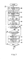
- processing for resetting a wheel speed calculation number N, increasing the wheel speed calculation number N, and calculating a wheel speed variation D are respectively executed as at 100 through 102 in the first embodiment.
- the processing advances to 153 to calculate a front and rear wheel speed ratio ⁇ . This processing is the same as at 104 in the first embodiment.
- the CPU 3 determines whether the reference slip variation Aold has already been stored. For example, since the slip variation memorizing portion has memorized ⁇ before the reference slip variation Aold is memorized, the CPU 3 determines that the reference slip variation Aold has already been memorized when a value is memorized in the slip variation memorizing portion.
- This processing corresponds to regression line determining processing for determining whether a regression line is calculated, and is executed by a regression line determining portion (not shown) in the CPU 3.
- the processing advances to 155 when a determination by the CPU 3 is positive.
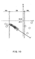
- the CPU 3 determines whether the wheel speed variation D and the front and rear wheel speed ratio ⁇ relatively calculated at 152. 153 fall within an available range. This processing is executed by an available range determining portion (not shown) in the CPU 3 as will now be described with reference to FIG. 9. Calculation results of a relationship between the wheel speed variation D and the front and rear wheel speed ratio ⁇ relatively calculated at 152, 153 are dotted in FIG. 9. A line A' is a regression line calculated at 159 as discussed later.
- a calculation speed of the wheel speed variation D and the front and rear wheel speed ratio ⁇ relatively is sufficiently faster than a tire air pressure decrease speed when the tire air pressure decreases due to, for example, a puncture hole caused by a nail. Accordingly, calculation results during the tire air pressure decreases are dotted on or near the line A'.
- calculation results are sometimes dotted to separate from the line A' as shown in FIG. 9. It is considerable that such calculation results include non-uniform components due to non-uniform rotation of vehicle wheels. Therefore, it is preferred that such calculation results be removed from data for calculating the regression line A'.
- a region that includes the line A' and regions having a predetermined width on both sides of the line A' from the line A' defines the available range, and other regions that exceed the available range define a non-available range.
- the processing returns at 151 when the calculation result is within the non-available range. Therefore, calculation results within the non-available range are not memorized at 156, 157 as discussed later.
- the processing at 154 advances to 156, 157 when a determination by the CPU 3 is negative because the reference slip variation Aold is 0.
- the wheel speed variation D is memorized in the memory of the wheel speed variation memorizing portion to add data of the already memorized wheel speed variations D(N).
- the front and rear wheel speed ratio ⁇ is memorized in the memory of the front and rear wheel speed ratio memorizing portion to add to data to the already memorized front and rear wheel speed ratio ⁇ (N).
- This processing is the same as at 103, 105 in the first embodiment.
- the CPU 3 determines whether the wheel speed calculation number N is larger than n 0 as at 106 in the first embodiment. The processing advances to 159 when a determination is positive, while returning at 151 when the determination is negative.
- a slip variation A is calculated as at 107 in the first embodiment.
- the processing then advances to 160, where the slip variation A calculated at first is memorized in the slip variation memorizing portion of the slip variation processing portion 3d as the reference slip variation Aold.
- processing as at 108 through 116 in the first embodiment is executed, and therefore the CPU 3 determines whether tire air pressure of some of the vehicle wheels 1a-1d decreases.
- the calculation results within the non-available range are removed at 105 and are not memorized at 156, 157. Therefore, the calculation results including non-uniform components due to non-uniform rotation of vehicle wheels are not used as data for calculating the regression line A'. Accordingly, the accuracy of the calculation of a regression line does not decrease due to the non-uniform rotation of vehicle wheels.
- the slip variation A is accurately calculated, and therefore an ideal driving status value ⁇ id and a post-compensation wheel speed variation D' AVE are accurately calculated.
- a warning pressure is as a result uniformity.
- the post-compensation wheel speed variation D' AVE which corresponds to a wheel speed variation D under ideal driving status when a tire air pressure of at least one of the driven wheels 1c, 1d decreases, is calculated without excessive compensation.
- the post-compensation wheel speed variation D' AVE when the tire air pressure of the driven wheel decreases and that when the tire air pressure of the non-driven wheel decreases are identical value. Therefore, the warning pressure is uniform regardless of the type of wheel that decreases in pressure.
- a third embodiment data within a region that is different from the non-uniform range defined in the second embodiment is removed.
- the configuration of a tire air pressure detection device of the third embodiment is the same as in the first and the second embodiments.
- the results calculated when at least one pair of vehicle wheels temporarily rotates with non-uniform are not used as data for calculating the regression line A'.
- the calculation results calculated during temporary tire slips or when shift shock of a transmission is generated are not used as data for calculating the regression line A'.
- the calculation results of the front and rear wheel speed ratio ⁇ are sometimes smaller than a lower threshold corresponding to a lowest value of an appropriate range thereof when some of the vehicle wheels 1a-1d instantaneously slip or are larger than a uppermost threshold corresponding to a highest value of the appropriate range when noise is generated by shift shock of the transmission. In such cases, it is better to remove such calculation results from data for calculating the regression line A'.
- the lower and the higher thresholds of the front and rear wheel speed ratio ⁇ are defined, the region between the lower and the higher thresholds is defined as an available range, and other regions that fall outside the available range are defined as a non-available range.
- the processing 154a and 155 is modified with respect to the processing 154 and 155 in the second embodiment.
- the CPU 3 determines whether a reference slip variation Aold memorized at 160 is larger than a predetermined threshold K. This processing is executed for determining whether a wheel in which tire air pressure decreases is a driven wheel or a non-driven wheel. A driven wheel determining portion (not shown) in the CPU 3 executes the processing.
- the front and rear wheel speed ratio fl exceeds the higher threshold because wheel speeds V FR , V FL of the non-driven wheels 1a, 1b are higher than wheel speeds V RR , V RL of the driven wheels 1c 1d.
- the calculation results do not include non-uniform components due to non-uniform rotation of vehicle wheels.
- the reference slip variation Aold is compared to the predetermined threshold K to remove calculation results from data for calculating the regression line A' only when the tire air pressure of one of the driven wheels 1c, 1d decreases.
- the processing returns at 151 because a wheel in which tire air pressure decreases is one of the non-driven wheels 1a. 1b.
- the processing advances to 155 because a wheel in which tire air pressure decreases is one of the driven wheels 1c, 1d.
- the CPU 3 determines whether the front and rear wheel speed ratio ⁇ calculated at 153 falls within the available range.
- the processing advances to 156 and beyond when a determination at 155 is positive. To the contrary, the processing returns to 151 when the determination at 155 is negative. Thus, the calculation results within the non-available range are removed and are not memorized at 156, 157.
- the tire air pressure detection device of the present embodiment lower and higher thresholds of the front and rear wheel speed ratio ⁇ are defined when tire air pressure of one of the driven wheels decreases. Therefore, the calculation results including non-uniform components due to non-uniform rotation of vehicle wheels caused by temporary tire slippage or shift shock of a transmission are not used for calculating the regression line A'. Accordingly, the accuracy of the calculation of a regression line does not decrease due to the non-uniform rotation of vehicle wheels, and a warning pressure remains uniform.
- a fourth embodiment data within a region that is different from the non-uniform ranges defined in the second and third embodiments is removed.
- the configuration of a tire air pressure detection device of the fourth embodiment is the same as in the third embodiment.
- the calculation results calculated when noise is generated are not used as data for calculating the regression line A'.
- the noise caused by deceleration occurs when tire air pressure of one of the driven wheels 1c, 1d decreases
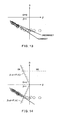
- the calculation results of a relationship between a wheel speed variation D and a front and rear wheel speed ratio ⁇ are dotted as shown in FIG. 13.
- the calculation results are sometimes higher than the line of the linear function when the noise caused by deceleration occurs. If such calculation results are used for calculating the regression line A', the regression line A' may be incorrect as shown in FIG. 13. Therefore, it is better to remove such calculation results from the data used for calculating the regression line A'.
- the tire air pressure detection processing as shown in FIGS. 11 and 12 in the third embodiment is executed.
- processing when the tire air pressure of one of the non-driven wheels 1a, 1b is the same as in the third embodiment. That is, calculation results when the tire air pressure of one of the driven wheels 1c, 1d decreases are only removed from the data for calculating the regression line A'.
- FIG. 15 is a schematic view showing a tire air pressure detection device according to a fifth embodiment of the present invention.
- the tire air pressure detection device is described with reference to FIG. 15.
- the tire air pressure detection device has almost the same configuration as that of the first embodiment, and the tire air pressure determining processing is approximately the same as in the first embodiment, elements and processing different from the first embodiment will now be described.
- the tire air pressure detection device of the present embodiment includes a regression line accuracy evaluating portion 3i.
- the regression line accuracy evaluating portion 3i calculates a slip variation AA that is used for calculating a post-compensation wheel speed variation average D' AVE based on data memorized in the front and rear wheel speed ratio memorizing portion of a front and rear wheel speed ratio processing portion 3c.
- the regression line accuracy evaluating portion 3i evaluates a regression line accuracy based on a front and rear wheel speed ratio ⁇ memorized in the front and rear wheel speed ratio memorizing portion.
- a evaluation of the regression line is executed by determining whether a difference Ep between a maximum value and a minimum value of the front and rear wheel speed ratio ⁇ is larger than a predetermined reference value Ep*+Eth.
- the regression line accuracy evaluating portion 3i corresponds to a non-uniform detecting portion for detecting non-uniform of driven forces and a slip variation memorizing portion for memorizing the slip variation A.
- a wheel speed variation compensating portion in a wheel speed variation compensating processing portion 3f calculates a post-compensation wheel speed variation D' AVE based on the slip variation AA memorized in the regression line accuracy evaluating portion 3i.
- the post-compensation wheel speed variation D' AVE is calculated by the following equation (6), and a pressure difference determination value ⁇ D' AVE and the like are calculated based on the post-compensation wheel speed variation D' AVE .
- D' AVE D AVE +AA ( ⁇ id - ⁇ AVE )
- processing as at 100 through 110 in the first embodiment is executed.
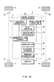
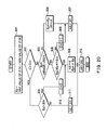
- the processing advances to 191 to execute regression line accuracy evaluating processing by regression line accuracy evaluating portion 3i.
- the regression line accuracy evaluating processing is described with reference to FIG. 18.
- the regression line accuracy evaluating portion 3i calculates a difference Ep between a maximum value and a minimum value of the front and rear wheel speed ratio ⁇ based on data memorized in the front and rear wheel speed ratio memorizing portion.
- the difference Ep corresponds to a determination reference value for determining whether non-uniform of the front and rear wheel speed ratio ⁇ occurs.
- the regression line accuracy evaluating portion 3i determines whether a difference stock value Ep* is memorized. That is, whether the difference Ep is calculated at least once or not is determined.
- the processing advances to 203 when a determination at 202 is negative to memorize the currently calculated difference Ep as the difference stock value Ep* and the slip variation A calculated at 187 as the variation stock value A* in the regression line accuracy evaluating portion 3i.
- the processing advances to 204 when the determination at 202 is negative.
- the regression line accuracy evaluating portion 3i determines whether the difference Ep is larger than the predetermined reference value Ep*+Eth that corresponds to a value added the difference stock value Ep* and threshold Eth.
- the non-uniformity of the wheel driven force relates to the non-uniformity of the front and rear wheel speed ratio ⁇ .
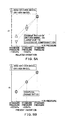
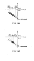
- FIGS. 19A and 19A respectively show relationships between a wheel speed variation D and the front and rear wheel speed ratio ⁇ when non-uniform of wheel driven force respectively occurs and does not occur.
- an error range of the slope of the regression line decreases when the non-uniform of the wheel driven force occurs, while it increases when the non-uniform of the wheel driven force does not occur. Therefore, the reliability of a slip variation A calculated when the non-uniform of the wheel driven force occurs is high, while that calculated when the non-uniform of the wheel driven force does not occur is not high.
- the processing advances to 205 when a determination at 204 is negative because the non-uniform of the wheel driven force does not occur and the reliability may not be high.
- the regression line accuracy evaluating portion 3i memorizes the variation stock value A* as the slip variation AA for calculating a post-compensation wheel speed variation average D' AVE .
- the processing advances to 206 when the determination at 204 is positive because the non-uniform of the wheel driven force may occur and the reliability may be high.
- the regression line accuracy evaluating portion 3i memorizes the slip variation A calculated now as the slip variation AA for calculating the post-compensation wheel speed variation average D' AVE and the difference Ep calculated now as the difference stock value Ep*.
- the processing advances to 207.
- the regression line accuracy evaluating portion 3i memorizes slip variation AA memorized at 205 or 206 as the variation stock value A*.
- regression line accuracy evaluating processing is completed.
- the post-compensation wheel speed variation average D' AVE is calculated based on the slip variation AA. Then, at 193-197, processing as at 112 through 116 in the first embodiment is executed, and therefore the CPU 3 determines whether tire air pressure of some of the vehicle wheels 1a-1d decreases.
- a slip value A is calculated when the non-uniformity of a wheel driven force does not occur, it is not used for calculating a post-compensation wheel speed variation average D' AVE .
- a slip value A calculated before the non-uniformity of a wheel driven force does not occur is applied as the slip value AA that is used for calculating a post-compensation wheel speed variation average D' AVE .
- a time when the non-uniform of the wheel driven force is small is sufficiently shorter than a time when tire air pressure decreases. Accordingly, a tire air pressure decrease can be detected even if the slip value A calculated before the non-uniform of a wheel driven force does not occur is applied as the slip value AA that is used for calculating a post-compensation wheel speed variation average D' AVE .
- the post-compensation wheel speed variation D' AVE which corresponds to wheel speed variation D under ideal driving status when the tire air pressure of at least one of the driven wheels 1c, 1d decreases, is calculated without excessive compensation.
- the post-compensation wheel speed variation D' AVE when the tire air pressure of the driven wheel decreases and that when the tire air pressure of the non-driven wheel decreases are identical. Therefore, regardless of which type of tire experiences a decrease in tire air pressure, the warning pressure is uniform.
- regression line accuracy evaluating processing is modified with respect to the fifth embodiment.
- the configuration of the tire air pressure detection device of the present embodiment is the same as in the first embodiment.
- processing as at 201 in the fifth embodiment is executed to calculate a difference Ep between a maximum value and a minimum value of the front and rear wheel speed ratio ⁇ .
- the processing advances to 303 when a determination at 302 is negative.
- a regression line accuracy evaluating portion 3i determines whether a difference stock value Ep* is memorized as at 202 in the fifth embodiment.
- the processing then advances to 304 when a determination at 303 is negative.
- the regression line accuracy evaluating portion 3i memorizes the difference Ep calculated now as the difference stock value Ep* and the slip variation A calculated at 187 as the variation stock value A* as at 203 in the fifth embodiment.
- the processing advances to 305 when the determination at 303 is positive.
- the regression line accuracy evaluating portion 3i determines whether the difference Ep is larger than a predetermined reference value Ep*+Eth as at 204 in the fifth embodiment.
- the processing advances to 306 and 307 when a determination is negative.
- the counts of counter is incremented.
- the regression line accuracy evaluating portion 3i memorizes the variation stock value A* therein as the slip variation AA as at 205 in the fifth embodiment.
- the processing advances to 308 when a determination is positive.
- the regression line accuracy evaluating portion 3i memorizes the slip variation A calculated now as the slip variation AA and the difference Ep calculated now as the difference stock value Ep* as at 206 in the fifth embodiment.
- the processing advances to 309 when the determination at 302 is positive.
- the regression line accuracy evaluating portion 3i determines whether the difference Ep is larger than a predetermined threshold value Eth'.
- the predetermined threshold value Eth' is a value smaller than the predetermined reference value Ep*+Eth.
- the processing then advances to 308 to memorize the slip variation A calculated now as the slip variation AA and the difference Ep calculated now as the difference stock value Ep* in the regression line accuracy evaluating portion 3i.
- the processing advances to 311 when the determination at 309 is negative.
- the regression line accuracy evaluating portion 3i memorizes the variation stock value A* therein as the slip variation AA as at 307.
- the processing then advances to 312 to memorize the slip variation AA memorized at 307, 308 or 311 as the variation stock value A* in the regression line accuracy evaluating portion 3i.
- regression line accuracy evaluating processing is completed.
- a variation stock value A* is renewed at a slip variation A calculated now (at 308, 312). Further, when the variation stock value A* is not renewed if a predetermined time has passed, a difference Ep is compared with a predetermined threshold Eth' (at 309). Then, when the difference Ep is larger than the predetermined threshold Eth', the variation stock value A* is renewed by current slip value A. This is because the non-uniformity of the wheel driven force is small, but the regression line can be calculated accurately to some degree.
- FIG. 21 is a schematic view showing a tire air pressure detection device according to a seventh embodiment of the present invention.
- the tire air pressure detection device is described, with reference to FIG. 21.
- the tire air pressure, detection device has almost the.same configuration as in the first embodiment, and the tire air pressure determining processing is approximately the same as in the first embodiment, only elements and processing different from the first embodiment will now be described.
- the tire air pressure detection device of the present embodiment includes a left and right non-driven wheel speed ratio processing portion 3j.
- the left and right non-driven wheel speed ratio processing portion 3j includes a left and right non-driven wheel speed ratio calculating portion, a left and right non-driven wheel speed ratio determining portion, a left and right non-driven wheel speed ratio memorizing portion, and a left and right non-driven wheel speed ratio averaging portion.
- the left and right non-driven wheel speed ratio determining portion determines whether the left and right non-driven wheel speed ratio R is in an available range. Thus, the left and right non-driven wheel speed ratio R within the available range is selected, while that outside of the available range is removed. A selection of the left and right non-driven wheel speed ratio R is executed by a selecting portion (not shown) in the CPU 3. When the left and right non-driven wheel speed ratio R is determined in the available range, it is memorized in the left and right non-driven wheel speed ratio memorizing portion.
- the available range is defined based on an average value R AVE of the left and right non-driven wheel speed ratio R that is calculated by the left and right non-driven wheel speed ratio averaging portion. Specifically, a range including from the average value R AVE minus Rw to the average value R AVE plus Rw (R AVE - Rw ⁇ R ⁇ R AVE + Rw) is defined as the available range.
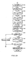
- a 1 st flag is set in F.
- the 1 st flag expresses whether a calculation executed as follows is executed for the first time. That is, the calculation is executed for the first time when the 1 st flag is F, while it is not executed for the first time when the 1 st flag is T.
- the 1 st flag is set in T if a wheel speed calculation number N reaches n 0 one time as shown at 412, 413.
- non-driven wheel speeds (V FL , V FR ) are selected from respective wheel speeds calculated at 402, and a left and right non-driven wheel speed ratio R is calculated based on the non-driven wheel speeds.
- whether the 1 st flag is f or T is determined. The processing advances to 405 when the 1 st flag is T, or advances to 406 when the 1 st flag is F.
- the left and right non-driven wheel speed ratio determining portion determines whether the left and right non-driven wheel speed ratio R calculated at 403 is in the available range (R AVE - Rw ⁇ R ⁇ R AVE + Rw).
- the processing advances to 406 when a determination at 405 is positive, or returns to 402 when the determination is negative.
- This processing corresponds to data selecting processing to remove data outside of the available range and select data within the available range.
- the wheel speed calculation number N is incremented.
- the processing then advances to 407 to memorize the left and right non-driven wheel speed ratio R within the available range in the left and right non-driven wheel speed ratio memorizing portion to add currently memorized left and right non-driven wheel speed ratio R(N).
- R(N) corresponds an arrangement of n 0 portions of the left and right non-driven wheel speed ratio R to memorize n 0 portions of left and right non-driven wheel speed ratio R into a position of the memory corresponding to a calculated number.
- the left and right non-driven wheel speed ratio memorizing portion re-memorizes a new left and right non-driven wheel speed ratio R into the position of the memory corresponding to wheel speed calculation number N when, for example, the wheel speed calculation number N is reset at 401 after the n 0 portions of the left and right non-driven wheel speed ratio R are memorized.
- processing as at 102 through 106 in the first embodiment is executed, and the processing then advances to 413.
- the 1 st flag is set in T to express that the calculation is not being executed for the first time.
- processing as at 107 in the first embodiment is executed to calculate a slip variation A.
- the processing then advances to 415, and the average value R AVE of the left and right non-driven wheel speed ratio R is calculated.
- the average value R AVE of the left and right non-driven wheel speed ratio R is calculated by substituting respective left and right non-driven wheel speed ratios R memorized at 407 into the equation (7).
- processing as at 108 through 116 in the first embodiment is executed, and therefore the CPU 3 determines whether the tire air pressure of some of the vehicle wheels 1a-1d decreases.
- the left and right non-driven wheel speed ratios R outside of the available range are removed and thus are not used for calculating a regression line, and those ratios within the available range are used for calculating the regression line.
- a relationship between the left and right non-driven wheel speed ratios R and the available range is shown in FIG. 24.
- the available range is not defined until the wheel speed calculation number N is n 0 , but is renewed every time when the wheel speed calculation number N is n 0 .
- calculated left and right non-driven wheel speed ratio R is outside the available range, its data is not memorized in the first wheel speed variation memorizing portion and the front and rear wheel speed ratio memorizing portion.
- adopted data does not include data when the vehicle turns.
- an accurate regression line is calculated based on the adopted data. Accordingly, the accuracy of the calculation of a regression line does not decrease due to the non-uniform of wheel speed variation D caused by events such as vehicle turns and a warning pressure is uniform.
- the post-compensation wheel speed variation D' AVE which corresponds to a wheel speed variation D under ideal driving status when a tire air pressure of at least one of the driven wheels 1c, 1d decreases, is calculated without excessive compensation.
- the post-compensation wheel speed variation D' AVE when the tire air pressure of the driven wheel decreases and that when the tire air pressure of the non-driven wheel decreases are identical. Therefore, regardless of the type of wheel experiencing a decrease in tire pressure, the warning pressure is uniform.
- respective tire air pressure detection devices are adapted for use in a rear wheel drive vehicle, but can alternatively be adapted for use in a front wheel drive vehicle.
- an ideal driving status value ⁇ id is at least 1 with respect to the tire air pressure decrease of a driven wheel.
- the wheel speed variation D is calculated as a rotational status value using equation (1).
- the rotational status value is a value expressing a relationship of respective wheels 1a-1d so as to cancel a wheel speed variation between left and right wheels generated due to vehicle turns.
- a slip variation A a slope of a regression line
- the slip variation A is approximately zero. Therefore, upon removing the compensation when the slip variation A is small, it is possible to remove data when compensation is not needed even if a tire air pressure of one of the rear wheels decreases and when a tire air pressure of one of the front wheels decreases.
- are calculated based on n 0 portions of the wheel speed variations D and the front and rear wheel speed ratios ⁇ when the wheel speed calculation number N reaches n 0 .
- a tire air pressure decrease is not detected until all n 0 portions of data are renewed. Accordingly, upon moving average, a tire air pressure decrease can be detected even if all n 0 portions of data are not renewed.
- the moving average renews the oldest data of the wheel speed variations D and the front and rear wheel speed ratios ⁇ memorized in the wheel speed variation memorizing portion and the front and rear wheel speed ratio memorizing portion. Then, the average value D AVE and the average value ⁇ AVE are periodically calculated when one of the wheel speed variations D and one of the front and rear wheel speed ratios ⁇ are renewed.
- the above-mentioned regression line accuracy evaluating processing can alternatively be adapted for other tire air pressure detection device that uses a compensation methodology disclosed by the already discussed related art device.
Landscapes
- Engineering & Computer Science (AREA)
- Mechanical Engineering (AREA)
- Measuring Fluid Pressure (AREA)
Abstract
A tire air pressure detection device includes an ideal
driving status calculating portion (3e) and a rotational
status value compensating portion (3f). The ideal driving
status calculating portion calculates an ideal status value
(β id) corresponding to a slip value under an ideal driving
status without tire slippage. The rotational status value
compensating portion calculates an ideal rotational status
value under the ideal driving status without tire slip based
on the regression line calculated by a regression line
calculating portion (3d) and the ideal slip status value
calculated by the ideal driving status calculating portion.
Description
The present invention relates to a device for detecting a
tire air pressure based on a vehicle speed signal.
JP-A-H10-100624 discloses a conventional tire air pressure
detection device. The tire air pressure device detects a
decrease in tire air pressure based on wheel speed variation D
and a front and rear wheel speed ratio β . The wheel speed
variation D and the front and rear wheel speed ratio β are
expressed as follows, where VFR corresponds to front right wheel
speed, VFL corresponds front left wheel speed, VRR corresponds rear
right wheel speed and VRL corresponds rear left wheel speed.
D = VFR VFL -VRR VRL
B = VFR + VFL VRR + VRL
The wheel speed variation D represents a rotational status
value calculated based on wheel speeds of four vehicle wheels.
For example, the wheel speed variation D is a variable defined
as a difference of wheel speed ratios of each pair of wheels
located diagonally from each other, and increases or decreases
when the tire air pressure of some of the vehicle wheels decrease.
The front and rear wheel speed ratio β is a tire slip status value
that denotes a degree of slip status of driven wheels caused by
transmitted driving forces. For example, the smaller the front
and rear wheel speed ratio β is, the higher the slip of one (or
both) of the driven wheels is.
The wheel speed variation D increases or decreases when the
tire air pressures of some of the vehicle wheels decreases below
a standard value, and it is zero when each tire air pressure of
each tire equals the standard value. Therefore, the tire pressure
decrease is detected based on the wheel speed variation D.
However, regarding, for example, a rear wheel drive vehicle,
when the tire air pressure of the rear right wheel corresponding
to one of the driven wheels decreases below the standard value,
the other driven wheel tends to slip easier than the rear right
wheel because a ground contact area of the rear right wheel
increases and resistance force for suppressing the slip increases
even if the diameter of the rear right wheel decreases due to the
tire air pressure decrease. Accordingly, the wheel speed
variation D varies based on the degree of slip status of the
wheels.
Thus, as shown in FIG. 26, a regression line is calculated
based on a relationship of the front and rear wheel speed ratio
β and the wheel speed variation D using a minimum square
calculation methodology. An ideal value of the wheel speed
variation D is then calculated by compensating for the wheel speed
variation D (or an average DAVE). An ideal value of the wheel speed
variation D is a value of the wheel speed variation D if the slip
does not occur when the front and rear wheel speed ratio β is
1. Thus, the effect of the slip of the driven wheels is removed,
and therefore the tire air pressure decrease can accurately be
detected.
The ideal wheel speed variation value D is calculated under
the condition that the front and rear wheel speed ratio β is 1.
However, the front and rear wheel speed ratio β is not 1 when
the tire air pressure decreases. Therefore, the above
compensation is excessive. In this case, changes of the wheel
speed variation D of the driven wheels and non-driven wheels due
to the tire air pressure decrease are different, and a warning
pressure, which is a pressure at which a driver is warned, varies.
In the tire air pressure device mentioned above, the tire
air pressure decrease is detected under the assumption that the
driving force of the wheels usually varies. Therefore, if a
variation of the driving force of the wheels decreases when the
vehicle is driven on a flat road at a constant speed, values of
the front and rear wheel speed ratio β and the wheel speed
variation D do not vary. Referring to FIG. 27, when the accuracy
of the calculation of the regression line decreases because of,
for example, a small noise caused by a slight turning of the
vehicle, the compensation of the wheel speed variation D may not
be executed appropriately. As a result, the accuracy of tire air
pressure detection decreases.
The wheel speed variation D corresponding to the rotational
status value relates to not only the front and rear wheel speed
ratio β but also to non-uniform wheel rotation when the vehicle
is driving (e.g., the non-uniform wheel rotation is caused by
turning, driving on a bad road or shift shock of a transmission),
varies based on the non-uniform wheel rotation and is non-uniform
value. When the regression line is calculated based on the
non-uniform value, the accuracy of the calculation of the wheel
speed variation D decreases and therefore the warning pressure
varies.
Furthermore, the wheel speed variation D varies based on
the turn status of the vehicle as well as the slip status of the
driven wheels. For example, the relationship of the front and
rear wheel speed ratio β and the wheel speed variation D during
turning is plotted in FIG. 28. The plotted results are non-uniform
as compared with FIG. 26, which does not include data
during turning. Therefore, if the regression line is calculated
based on all plotted results, it is impossible to calculate an
accurate regression line as shown in FIG. 29. As a result, the
accuracy of the calculation of the wheel speed variation D
decreases, and therefore the warning pressure varies.
It is therefore object of the present invention to provide
a tire air pressure detection device that is capable of increasing
the accuracy of the rotational status value in an ideal driving
status by correcting excessive compensation when a tire air
pressure of driven wheels decreases.
It is another object of the present invention to provide
a tire air pressure detection device that is capable of obviating
warning pressure non-uniform.
It is further object of the present invention to provide
a tire air pressure detection device that is capable of accurately
detecting the tire air pressure even if driving force is small.
It is further object of the present invention to provide
a tire air pressure detection device that is capable of preventing
a decrease of accuracy of the calculation of the regression line
caused by variation of the rotational status value and obviating
warning pressure non-uniform.
Moreover, it is object of the present invention to provide
a tire air pressure detection device that is capable of preventing
a decrease of accuracy of the calculation of the regression line
due to non-uniform of the turn status of the vehicle and obviating
warning pressure non-uniform.
A tire air pressure detection device according to claim 1
includes a vehicle wheel speed detecting portion (2a-2d, 3a) for
detecting respective vehicle wheel speeds; a rotational status
value calculating portion (3b) for calculating a rotational value
(D) expressing a relationship of the respective vehicle wheel
speeds to cancel a wheel speed variation between left and right
wheels generated due to vehicle turns; a slip status value
calculating portion (3c) for calculating a slip status value (β)
based on the vehicle wheel speeds detected by the vehicle wheel
speed detecting portion, the slip status value depending on a slip
status between driven wheels and non-driven wheels; a regression
line calculating portion (3d) for calculating a regression line
that is a linear function expressing a relationship between the
rotational status value calculated by the rotational status value
calculating portion and the slip status value calculated by the
slip status value calculating portion; an ideal driving status
calculating portion (3e) for calculating an ideal status value
(β id)corresponding to a slip value under an ideal driving status
without tire slippage; a rotational status value compensating
portion (3f) for calculating an ideal rotational status value
under the ideal driving status without tire slippage based on the
regression line calculated by the regression line calculating
portion and the ideal slip status value calculated by the ideal
driving status calculating portion; and a tire air pressure
decrease detecting portion (3h) for detecting a tire air pressure
decrease based on the ideal rotational status value calculated
by the rotational status value compensating portion The ideal
driving status calculating portion calculates an ideal status
value (β id) corresponding to a slip value under an ideal driving
status without tire slip.
The ideal driving status calculating portion calculates
the ideal slip status value (β id) corresponding to a slip status
value under the ideal driving status without tire slip. The
rotational status value compensating portion calculates the
ideal rotational status value based on the regression line
calculated by the regression line calculating portion and the
ideal slip status value.
According to the tire air pressure detection device, an
accurate rotational status value under the ideal driving status
without tire slip can be appropriately calculated without
excessive compensation when a tire air pressure of driven wheels
decreases.
Specifically, according to claim 2, the rotational status
value compensating portion calculates the ideal rotational
status value by assuming a rotational status value if the slip
status value is the ideal status value based on the regression
line calculated by the regression line calculating portion.
According to claim 3, the tire air pressure detection
device further includes a rotational status value averaging
portion (3b) for calculating a rotational status value average
(DAVE) of the rotational status value calculated by the rotational
status value calculating portion; and a slip status value
averaging portion (3c) for calculating a slip status value
average (βAVE of the slip status value calculated by the slip
status value calculating portion. The rotational status value
compensating portion calculates the ideal rotational status
value by compensating for the rotational status value average
calculated by the rotational status value averaging portion and
the slip status value average calculated by the slip status value
averaging portion based on the regression line calculated by the
regression line calculating portion.
The slip status value average and the rotational status
value average can be compensated for based on the regression line.
For example, according to claim 4, a wheel speed variation
(D) corresponding to a difference in wheel speed ratios of each
pair of wheels located diagonally from each other may be adopted
as the rotational status value. According to claim 5, a front
and rear wheel speed ratio (β ) corresponding to a ratio of
vehicle wheel speeds of front wheels and vehicle wheel speeds of
rear wheels may be adopted as the slip status value. When the
wheel speed variation and the front and rear wheel speed ratio
are adopted, the regression line calculating portion, according
to claim 6, calculates a change value (A) of the wheel speed
variation with respect to the front and rear wheel speed ratio.
Further, according to claim 7, the ideal driving status value
calculating portion calculates one of a linear function and a
quadratic function of the change value of the wheel speed
variation with respect to the front and rear wheel speed ratio,
and also calculates the ideal status value based on calculated
function of the change value.
A tire air pressure detection device according to claim 8
includes a selecting portion. The selecting portion selects a
rotational status value calculated by a rotational status value
calculating portion and a slip status value calculated by a slip
status value calculating portion within a predetermined
available range. A regression line calculating portion
calculates a regression line based on the rotational status value
and the slip status value selected by the selecting portion.
The tire air pressure detection device has the selecting
portion for selecting the rotational status value calculated by
the rotational status value calculating portion and the slip
status value calculated by the slip status value calculating
portion within the predetermined available range. Thus, the
calculation of the regression line by the regression line
calculating portion is carried out based on the rotational status
value and the slip status value within the predetermined
available range selected by the selecting portion. Therefore,
the accuracy of the calculation of the regression line does not
decrease due to non-uniform of the rotational status value, and
therefore a warning pressure is uniform.
A tire air pressure detection device according to claim 9
includes a regression line determining portion for determining
whether the regression line is calculated by the regression line
calculating portion. The selecting portion does not execute a
selection when the regression line determining portion has
determined that the regression line is not yet calculated, and
executes the selection when the regression line determining
portion has determined that the regression line has already been
calculated. The selection by the selecting portion can be
executed after a first regression line is calculated.
According to claim 10. the selecting portion may define the
predetermined available range based on the regression line
calculated by the regression line calculating portion before the
selection is not yet executed. For example, according to claim
11, the selecting portion defines a region that includes the
regression line and regions having predetermined width on both
sides of the regression line as the available range. Accordingly,
the variation of the rotational status value caused by vehicle
turns is inhibited.
A tire air pressure detection device according to claim 12
includes a driven wheel determining portion for determining
whether a wheel in which tire air pressure decreases is a driven
wheel. The selecting portion defines at least one of higher and
lower thresholds as the available range when the driven wheel
determining portion determines that the wheel in which the tire
air pressure decreases is the driven wheel.
According to the tire air pressure detection device, when
the wheel in which the tire air pressure decreases is the driven
wheel, the higher threshold as the available range prevents the
rotational status value from varying caused by temporary tire
slippage. Further, the lower threshold as the available range
prevents the rotational status value from varying caused by shift
shock of a transmission.
A tire air pressure detection device according to claim 13
includes an ideal driving status calculating portion (3e) for
calculating an ideal status value (β id=F(A)) corresponding to
a slip value when there is no tire slippage. The rotational status
value compensating portion calculates an ideal rotational status
value when there is no tire slippage based on the regression line
calculated by the regression line calculating portion and the
ideal slip status value calculated by the ideal driving status
calculating portion.
The tire air pressure detection device calculates the ideal
rotational status value based on the regression line and the ideal
driving status. Therefore, the tire air pressure detection
device can accurately detect a tire air pressure decrease using
the ideal rotation status value.
A tire air pressure detection device according to claim 14
includes a driven wheel determining portion for determining
whether a wheel in which a tire air pressure decreases is a driven
wheel. The selecting portion defines a region in which the slip
status value is lower than the regression line as the available
range when the driven wheel determining portion has determined
that the wheel in which the tire air pressure decreases is the
driven wheel. The available range inhibits the variation of the
rotational status value due to a noise caused by deceleration.
According to claim 15, the driven wheel determining portion
determines whether the wheel in which the tire air pressure
decreases is the driven wheel based on a slope of the regression
line calculated by the regression line calculating portion. In
detail, according to claim 16, the driven wheel determining
portion determines that the wheel in which the tire air pressure
decreases is the driven wheel when the slope of the regression
line is larger than a predetermined threshold (K).
A tire air pressure detection device according to claim 17
includes a non-uniformity detecting portion (3i) that detects the
non-uniform of wheel driving forces. The rotational status value
compensating portion compensates for the rotational value based
on a present regression line calculated by the regression line
calculating portion when the non-uniform detecting portion has
detected the non-uniformity of the driven forces, while
compensating for the rotational value based on a prior regression
line calculated by the regression line calculating portion when
the non-uniform detecting portion has not detected the non-uniformity
of the driven forces.
According to the tire air pressure detection device, the
rotational value is compensated for based on a present regression
line calculated by the regression line calculating portion when
the non-uniformity of the driven forces is generated. The
rotational value is compensated for based on a prior regression
line calculated by the regression line calculating portion when
the non-uniformity of the driven forces is not generated.
Therefore, even if the wheel driven force non-uniformity does not
occur, a small noise caused by a slight vehicle turn does not
diminish the accuracy of the calculation of a regression line.
The tire air pressure detection device can accurately detect a
tire air pressure decrease.
For example, according to claim 18, the non-uniformity of
the driven forces is detected based on non-uniformity of the slip
status value calculated by the slip status value calculating
portion. According to claim 19, the non-uniformity of the driven
forces based on non-uniform of the front and rear wheel speed
ratio (β) corresponding to a ratio of vehicle wheel speeds of
front wheels and vehicle wheel speeds of rear wheels.
In these case, according to claim 20, the tire air pressure
detection device can be provided with a front and rear wheel speed
ratio memorizing portion (3c) for memorizing the front and rear
wheel speed ratio calculated by the slip status value calculating
portion. The non-uniform of the driven forces can be detected
based on a difference (Ep) between a maximum value and a minimum
value of the front and rear wheel speed ratio. Further, according
to claim 21, the non-uniform of the driven forces can be detected
when the difference between the maximum value and the minimum
value of the front and rear wheel speed ratio is larger than a
first reference value (Ep*+Eth).
In a tire air pressure detection device according to claim
22, the non-uniform detecting portion defines a second reference
value (Eth') larger than the first reference value when the slip
variation is not renewed for a predetermined time (Cth), and
detects the non-uniform of the driven forces when the difference
between the maximum value and the minimum value of the front and
rear wheel speed ratio is larger than the second reference value.
Therefore, the situation in which slip variation is not
renewed for a long time, and data that is too old is used for
detecting a tire air pressure decrease, can be avoided. As a
result, tire air pressure decrease can be detected more
accurately.
According to claim 23, the regression line calculating
portion calculates a change value (A) of the wheel speed variation
with respect to the front and rear wheel speed ratio. The
rotational status value compensating portion compensates for the
rotational status value calculated by the rotational status value
calculating portion based on the slip variation. Thus, the
rotational status value is compensated for based on the slip
variation.
In this case, according to claim 24, the tire air pressure
detection device includes a slip variation memorizing portion for
memorizing the slip variation calculated by the regression line
calculating portion. The slip variation memorizing portion
renews a previously calculated slip variation to a presently
calculated slip variation when the non-uniform of the driven
forces detected by the non-uniform detecting portion is larger
than a first reference value (Ep*+Eth). The rotational status
value compensating portion compensates for the rotational status
value calculated by the rotational status value calculating
portion based on the slip variation memorized in the slip
variation memorizing portion.
A tire air pressure detection device according to claim 25
includes an ideal driving status calculating portion (3e) for
calculating an ideal status value (β id=F(A)) corresponding to
a slip value when there is no tire slippage. The rotational status
value compensating portion calculates an ideal rotational status
value when there is no tire slippage based on the regression line
calculated by the regression line calculating portion and the
ideal slip status value calculated by the ideal driving status
calculating portion.
The tire air pressure detection device calculates the ideal
rotational status value based on the regression line and the ideal
driving status. Therefore, the tire air pressure detection
device can accurately detect a tire air pressure decrease using
the ideal rotation status value.
A tire air pressure detection device according to claim 26
includes a selecting portion (3j) for selecting data from data
regarding the wheel speeds detected by the wheel speed detecting
portion by removing data when the vehicle turns based on left and
right non-driven wheels speeds (VFL, VFR). The rotational status
value calculating portion calculates the rotational status value
and the slip status value calculating portion calculates the slip
status value based on the data selected by the selecting portion.
According to the tire air pressure detection device, the
selecting portion selects data regarding the wheel speeds
detected by the wheel speed detecting portion to remove data when
the vehicle turns. The rotational status value and the slip
status value are then calculated based on selected data.
Accordingly, the accuracy of the calculation of the regression
line does not decrease due to non-uniform of the rotational status
value caused by the vehicle turns, and therefore a warning
pressure is uniform.
For example, according to claim 27, the selecting portion
can include a left and right non-driven wheel speed ratio
calculating portion for calculating a left and right non-driven
wheel speed ratio (R) based on data of left and right non-driven
wheel speeds detected by the wheel speed detecting portion. In
this case, the selecting portion defines an available range based
on the left and right non-driven wheel speed ratio calculated by
the left and right non-driven wheel speed ratio calculating
portion, and selects the data based on whether the left and right
non-driven wheel speed ratio is in the available range.
A tire air pressure detection device according to claim 28
includes a selecting portion for defining an available range
based on data regarding left and right non-driven wheel speeds
included in the wheel speeds detected by the wheel speed detecting
portion, and selecting data within the available range from the
data regarding left and right non-driven wheel speeds. The
rotational status value calculating portion calculates the
rotational status value and the slip status value calculating
portion calculates the slip status value based on the data
selected by the selecting portion. The available range is defined
initially based on the data regarding left and right non-driven
wheel speeds, and is then repeatedly renewed each time the
selecting portion selects the data regarding left and right
non-driven wheel speeds.
In this configuration, as well as claim 25, the accuracy
of the calculation of the regression line does not decrease due
to non-uniform of the rotational status value caused by the
vehicle turns, and therefore a warning pressure is uniform.
A tire air pressure detection device according to claim 29
includes a left and right non-driven wheel speed ratio
calculating portion for calculating a left and right non-driven
wheel speed ratio (R) based on data of left and right non-driven
wheel speeds (VFL, VFR) detected by the wheel speed detecting
portion, and a left and right non-driven wheel speed ratio
determining portion for defining an available range based on the
left and right non-driven wheel speed ratio calculated by the left
and right non-driven wheel speed ratio calculating portion, and
determining whether the left and right non-driven wheel speed
ratio is in the available range. The left and right non-driven
wheel speed ratio determining portion selects the data within the
available range from data regarding the wheel speed detected by
the wheel speed detecting portion. The rotational status value
calculating portion calculates the rotational status value and
the slip status value calculating portion calculates the slip
status value based on the data selected by the left and right
non-driven wheel speed ratio determining portion.
According to the tire air pressure detection device, since
the rotational status value and the slip status value are then
calculated based on data selected by the left and right non-driven
wheel speed ratio determining portion, it is possible to obtain
the same advantage as in claim 25.
In this case, according to claim 30, the left and right
non-driven wheel speed ratio determining portion can define the
available range based on an average value (RAVE) of the left and
right non-driven wheel speed ratio calculated by the left and
right non-driven wheel speed ratio calculating portion.
Specifically, according to claim 31, the left and right non-driven
wheel speed ratio determining portion defines a region
(RAVE - Rw < R < RAVE + Rw) defined from a first value corresponding
to average value minus a predetermined value (Rw) to a second
value corresponding to average value plus the predetermined value
as the available value.
Other objects, features and advantages of the present
invention will be understood more fully from the following
detailed description made with reference to the accompanying
drawings in which:
The present invention will be described further with
reference to various embodiments shown in the drawings.
Referring to FIG. 1, a tire air pressure detection device
is for detecting a decrease in tire air pressure of one of the
vehicle wheels and is for warning a driver. The tire air pressure
detection device is applicable to both front or rear wheel drive
vehicles. However, in the present embodiment, the tire air
pressure detection device will be described with reference to a
rear wheel drive vehicle.
The tire air pressure detection device includes vehicle
wheel speed sensors 2a, 2b, 2c and 2d, which are located around
respective vehicle wheels 1a, 1b, 1c and 1d, a central processing
unit (CPU) 3 and a warning device 4. The CPU 3 receives input
signals from the vehicle wheel speed sensors 2a-2d and determines
whether tire air pressure in one or more of the vehicle wheels
1a-1d decreases to output a warning signal to the warning device
4. Incidentally, the vehicle speed sensors 2a-2d correspond
vehicle speed detecting portions.
The vehicle wheel speed sensors 2a, 2b respectively detect
and output wheel speed signals of respective non-driven wheels
(i.e., left and right front wheels). The vehicle wheel speed
sensors 2c, 2d detect and output wheel speed signals of respective
driven wheels (i.e., left and right rear wheels).
The CPU 3 is a microcomputer or the like and calculates
respective values based on detected signals from the vehicle
wheel speed sensors 2a-2d. The CPU 3 is constructed as follows.
The CPU 3 includes a vehicle wheel speed calculation
portion 3a and a vehicle wheel speed variation processing portion
3b. The vehicle wheel speed calculation portion 3a calculates
respective vehicle wheel speeds of respective wheels 1a-1d based
on detected signals (e.g., pulse signals) from the vehicle wheel
speed sensors 2a-2d. The vehicle wheel speed variation
processing portion 3b includes a vehicle speed variation
calculating portion corresponding to a rotation status value
calculating portion, a first vehicle speed variation memorizing
portion, and a vehicle speed variation average processing portion.
Results calculated by the vehicle wheel speed variation
processing portion 3b are used for processing regarding a
relative vehicle speed variation D.
The wheel speed calculating portion 3a calculates the
respective vehicle wheel speeds of the respective wheels 1a-1d
based on detected signals from the vehicle wheel speed sensors
2a-2d. For example, respective vehicle wheel speeds VFL, VFR, VRL
and VRR are calculated based on signals from the vehicle wheel
speed sensors 2a-2d inputted over several seconds. The vehicle
wheel speed variation calculating portion then calculates a wheel
speed variation D using the above-mentioned equation (1) based
on data corresponding to calculated vehicle wheel speeds. The
resultant data of the wheel speed variation D is stored in a memory
included in the first wheel speed variation memorizing portion.
Also, the wheel speed variation average processing portion
calculates an average value DAVE of the wheel speed variations D
based on the resultant data of the wheel speed variation D. The
average value DAVE of the wheel speed variation D corresponds to
the average of n0 portions of the wheel speed variation D
expressed as the following equation.
DAVE = 1n0 SD(N)
The CPU 3 includes a front and rear wheel speed ratio
processing portion 3c. The front and rear wheel speed ratio
processing portion 3c includes a front and rear wheel speed ratio
calculating portion corresponding to a slip status value
calculating portion, a front and rear wheel speed ratio
memorizing portion, and a front and rear wheel speed ratio average
processing portion. In the front and rear wheel speed ratio
processing portion 3c, the front and rear wheel speed ratio
calculating portion calculates a front and rear wheel speed ratio
β using the above-mentioned equation (2) based on data from the
wheel speed calculating portion 3a. The resultant data of the
front and rear wheel speed ratio β is stored in a memory included
in the front and rear wheel speed ratio memorizing portion. Also,
the front and rear wheel speed ratio average processing portion
calculates the average value β AVE of the front and rear wheel speed
ratios β based on the resultant data of the front and rear wheel
speed ratio β. The average value β AVE of the front and rear wheel
speed ratios β corresponds to the average of n0 portions of the
front and rear wheel speed ratio β expressed in the following
equation.
βAVE = 1n0 Sβ(N)
The CPU 3 also includes a slip variation calculating
portion 3d, an ideal driving status value calculating portion 3e,
and a wheel speed variation compensating processing portion 3f.
The slip variation calculation portion 3d calculates slip
variation A based on the wheel speed variation D calculated by
the wheel speed variation calculating portion of the wheel speed
variation processing portion 3b, and the front and rear wheel
speed ratio β calculated by the front and rear wheel speed ratio
calculating portion of the front and rear wheel speed ratio
processing portion 3c. The slip variation A corresponds to the
change in value (ΔD/Δβ) of the wheel speed variation D with
respect to the front and rear wheel speed ratio β and is
calculated by a minimum square calculation methodology using n0
portions of the wheel speed variation D and the front and rear
wheel speed ratio β. The slip variation calculating portion 3d
corresponds to a regression line calculating portion.
The ideal driving status value calculating portion 3e
calculates an ideal driving status value β id based on
calculation results of the slip variation calculating portion 3d.
The ideal driving status value β id corresponds to the front and
rear wheel speed ratio β when the vehicle drives under ideal
status without tire slippage, is used as a standard compensation
value, and is calculated as a linear function, quadratic function
or the like of the slip variation A. That is, the ideal driving
status value β id is expressed by β id = F(A). For example, if
the ideal driving status value β id equals a liner function of
the slip variation A, it is expressed by β id = 1-Coef × |A|.
where Coef is constant.
The wheel speed variation compensating processing portion
3f includes a wheel speed variation compensating portion and a
second wheel speed variation memorizing portion. The wheel speed
variation compensating portion corresponds to a rotational
status value compensating portion. The wheel speed variation
compensating portion calculates a post-compensation wheel speed
variation D'AVE based on the average value DAVE of the wheel speed
variation D for each wheel, the average value βAVE of the front
and rear wheel speed ratios β, the slip variation A, and the ideal
driving status value β id. The post-compensation wheel speed
variation D'AVE corresponds to a wheel speed variation D for ideal
driving status. Specifically, the post-compensation wheel speed
variation D'AVE is calculated based on the following equation.
D' AVE = DAVE +A (βid- βAVE )
The second wheel speed variation memorizing portion
selects and memorizes reference value D'AVEstd based on the
post-compensation wheel speed variation D'AVE. The reference
value D'AVEstd corresponds to post-compensation wheel speed
variation D'AVE when tire air pressures of four wheels are
identical to be used for a reference value in determining tire
air pressure decrease. The reference value D'AVEstd is calculated
based on the average value DAVE of the wheel speed variation D for
each wheel, the average value βAVE of the front and rear wheel
speed ratios β, the slip variation A, and the ideal driving
status value β id calculated based on the wheel speed variation
D and the front and rear wheel speed ratio β calculated
immediately after the CPU 3 starts.
The CPU 3 further includes a pressure differential
threshold calculating portion 3g and a tire air pressure decrease
determination portion 3h. The pressure differential threshold
calculating portion 3g calculates a pressure difference
determination value ΔD'AVE based on the reference value D'AVEstd
memorized in the second wheel speed variation memorizing portion
and the post-compensation wheel speed variation D'AVE calculated
by the wheel speed variation compensating portion. The pressure
differential determination value ΔD'AVE equals a difference
between the reference value D'AVEstd and the post-compensation
wheel speed variation D'AVE (ΔD' AVE = D'AVEstd - D'AVE) and is used
for evaluating tire air pressure decrease.
The tire air pressure decrease determination portion 3h
compares an absolute value |ΔD' AVE| of the pressure differential
determination value ΔD' AVE to a predetermined threshold value Dsh
to determine tire air pressure decrease. Specifically, when the
absolute value | Δ D'AVE is higher than the predetermined
threshold value Dsh, the tire air pressure decrease determination
portion 3h transmits a warning signal denoting tire air pressure
decrease to the warning device 4. The warning device 4 warns a
vehicle driver of the tire air pressure decrease by causing a
warning light equipped in a vehicle passenger compartment to
blink.
Details of tire air pressure determination processing will
now be described with reference to FIGS. 2 and 3.
At 100, a wheel speed calculation number N of the wheel
speed is reset (N=0). At 101, as wheel speed calculating
processing is performed based on the detected signals from the
wheel speed sensors 2a-2d, the wheel speed calculating portion
3a calculates respective vehicle wheel speeds VFL, VFR VRL and VRR.
The CPU 3 then increases the wheel speed calculation number N.
The processing calculates respective wheel speed averages of each
wheel few several minutes based on the wheel speed pulse generated
during those few minutes.
At 102, during wheel speed variation calculating
processing, the wheel speed variation calculating portion of the
vehicle wheel speed processing portion 3b calculates the wheel
speed variation D. The wheel speed variation D is calculated by
substituting the respective vehicle wheel speeds VFL, VFR, VRL and
VRR calculated at 101 into equation (1).
At 103. the first wheel speed variation memorizing portion
memorizes the wheel speed variation D calculated at 102 to add
memorized wheel speed variations D(N). Incidentally, D(N)
corresponds to a stored arrangement of n0 portions of the wheel
speed variation D in a position of the memory corresponding to
a number of calculations. The first wheel speed variation
memorizing portion re-stores a new wheel speed variation D in the
position of the memory corresponding to wheel speed calculation
number N when, for example, the wheel speed calculation number
N is reset at 100 after the n0 portions of the wheel speed
variations D are memorized.
At 104, during front and rear wheel speed ratio calculating
processing, the front wheel speed ratio calculating portion of
the front wheel speed ratio processing portion 3c calculates a
front and rear wheel speed ratio β. The front and rear wheel
speed ratio β is also calculated by substituting the respective
vehicle wheel speeds VFL, VFR, VRL and VRR calculated at 101 into
equation (2). At 105, the memory of the front and rear wheel speed
ratio memorizing portion memorizes the front and rear wheel speed
ratio β calculated at 104 to add memorized front and rear wheel
speed ratios β (N). Incidentally, β(N) corresponds to an
arrangement of n0 memorized portions of the front and rear wheel
speed ratio β stored in a position of the memory corresponding
to the number of calculations. The front and rear wheel speed
ratio memorizing portion re-stores a new front and rear wheel
speed ratio β in the position of the memory corresponding to wheel
speed calculation number N as well as the D(N) after the n0
portions of the front and rear wheel speed ratios β are memorized.
At 106, the CPU 3 determines whether the wheel speed
calculation number N is larger than n0. The processing advances
to 107 when a determination at 106 is positive because n0 portions
of the wheel speed variation D of each wheel and the front and
rear wheel speed ratios β are memorized, and returns at 101 when
the determination at 106 is negative.
At 107, during slip variation calculating processing, the
slip calculating portion 3d calculates a slip variation A. That
is, a regression line corresponding to a linear function of the
wheel speed variation D and the front and rear wheel speed ratio
β is calculated, and the slip variation A is calculated based
on the regression line. The slip variation A expresses a
dependent degree of the wheel speed variation D with respect to
the front and rear wheel speed ratio β.
At 108, during wheel speed variation averaging processing,
the wheel speed variation averaging portion of the wheel speed
variation processing portion 3b calculates an average value DAVE
of the wheel speed variation D of each wheel. The average value
DAVE of the wheel speed variations D is calculated by substituting
respective wheel speed variations D memorized at 103 into
equation (3).
At 109, during front and rear wheel speed ratio averaging
processing, the front and rear wheel speed ratio averaging
processing portion of the front and rear wheel speed ratio
processing portion 3c calculates an average value βAVE of the
front and rear wheel speed ratios β stored in the memory. The
average of the front and rear wheel speed ratios β is calculated
by substituting respective front and rear wheel speed ratios β
memorized at 105 into equation (4).
At 110, during ideal driving status value calculating
processing, the ideal driving status value calculating portion
3e calculates an ideal driving status value β id. The ideal
driving status value β id is calculated based on the linear
function, quadratic function or the like of the slip variation
A calculated at 110.
At 111, during wheel speed variation compensating
processing, the wheel speed variation compensating portion of the
wheel speed variation compensating processing portion 3f
calculates a post-compensation wheel speed variation D'AVE by
substituting the average value DAVE, the average value βAVE, the
slip variation A, and the ideal driving status value β id
calculated at 107-110 respectively into equation (5).
At 112, the CPU 3 determines whether the reference value
D'AVE std has already been determined. The processing determines
whether the reference value D' AVEstd is stored in the memory of
the second wheel speed variation memorizing portion of the wheel
speed variation compensating processing portion 3f. If the
reference value D'AVEstd is calculated at first after the CPU 3
starts, the processing advances to 113 to store the post-compensation
wheel speed variation D'AVE calculated as a reference
value D'AVEstd and then returns to 100. On the other hand, if the
reference value D' AVEstd has already been stored, the processing
advances to 114.
At 114, for pressure difference threshold calculating
processing, the pressure difference threshold calculating
portion 3g calculates a pressure difference determination value
ΔD' AVE that corresponds to a difference between the reference
value D' AVEstd and the post-compensation wheel speed variation
D'AVE.
At 115, the tire air pressure decrease determination
portion 3h determines whether an absolute value |ΔD'AVE| of the
pressure difference determination value ΔD'AVE is larger than the
predetermined threshold value Dsh. The processing advances to
116 when a determination is positive. As a result, the tire air
pressure decrease determination portion 3h transmits a warning
signal denoting tire air pressure decrease to the warning device
4. The processing returns at 100 when the determination is
negative. Thus, the tire air pressure decrease of respective
wheels 1a-1d can be detected.
According to the tire air pressure detection device of the
present embodiment, the slip variation A is calculated based on
a wheel speed variation D and a front and rear wheel speed ratio
β. An ideal driving status value β id is then calculated based
on the slip variation A. Also, a post-compensation wheel speed
variation D'AVE is calculated based on an average value DAVE of the
wheel speed variation D of each wheel, an average value βAVE of
the front and rear wheel speed ratios β, the slip variation A,
and the ideal driving status value β id. Those relationships are
now described with reference to FIG. 4.
FIG. 4 shows a relationship between the wheel speed
variation D and the front and rear wheel speed ratio β when a
tire air pressure of one of the driven wheels 1c 1d (e.g., the
left rear wheel) decreases. In FIG. 4, white circles (○)
indicate n0 portions of the relationship between the wheel speed
variation D and the front and rear wheel speed ratio β, and black
circles () indicate a relationship between the average value
DAVE of the wheel speed variations D and the average value βAVE
of the front and rear wheel speed ratios β.
If the tire air pressure of the left rear wheel that is one
of the driven wheels 1c, 1d decreases, the vehicle wheel speed
VRL of the left rear wheel increases. Therefore, the front and
rear wheel speed ratio β decreases below 1 according to the tire
air pressure decrease. Since an ideal driving status value
β id satisfies the equation of βid = F(A) when there is no tire
slippage, it is therefore calculated based on the slip variation
A and the equation of β id = F(A) as at 110.
Further, as shown at 107, a regression line corresponding
to a linear function of n0 portions of the wheel speed variation
D and the front and rear wheel speed ratio β is calculated using
a minimum square calculation methodology.
Accordingly, as shown at 111, upon calculating an
intersection point of regression line and equation of β id =F(A),
a post-compensation wheel speed variation D'AVE, which
corresponds to a wheel speed variation D under ideal driving
status when a tire air pressure of at least one of the driven
wheels 1c, 1d decreases, is calculated. Thus, the post-compensation
wheel speed variation D'AVE can be appropriately
calculated without excessive compensation.
Therefore, as shown in FIG. 5A, in a tire air pressure
detection device of a related art device, a post-compensation
wheel speed variation change ratio when a tire air pressure of
a driven wheel decreases is different from that when a tire air
pressure of a non-driven wheel decreases. As a result, the
post-compensation wheel speed variation when the tire air
pressure of the driven wheel decreases is calculated as having
a value smaller than that when the tire air pressure of the
non-driven wheel decreases. To the contrary, as shown in FIG.
5B, in the tire air pressure detection device of the present
embodiment, the post-compensation wheel speed variation D'AVE
when the tire air pressure of the driven wheel decreases and that
when the tire air pressure of the non-driven wheel decreases are
identical. Therefore, regardless of which wheels decrease in
pressure, a warning pressure remains uniform.
In a second embodiment of the present invention shown in
FIG. 6, a tire air pressure detection device has a different
construction from that of the first embodiment. As shown in FIG.
6, in this embodiment, the tire air pressure detection device is
modified with respect to the tire air pressure detection device
of the first embodiment.
In the tire air pressure detection device of the second
embodiment, a slip variation processing portion 3d has a slip
variation calculating portion and a slip variation memorizing
portion. The slip variation calculating portion calculates slip
variation A based on a wheel speed variation D and a front and
rear wheel speed ratio β as in the first embodiment. The slip
variation memorizing portion memorizes a reference slip
variation Aold based on a calculation result of the slip variation
calculating portion. The reference slip variation Aold
corresponds to a latest slip variation A. For example, an
initially calculated slip variation A is stored as the reference
slip variation Aold, and a new slip variation A is then stored
as the reference slip variation Aold.
An ideal driving status value calculating portion 3e
calculates an ideal driving status value β id based on data stored
in the slip variation memorizing portion of the slip variation
processing portion 3d. Therefore, a post-compensation wheel
speed variation D' AVE and the like are calculated based on the
ideal driving status value β id calculated in above-described
manner.
Details of tire air pressure determination processing will
now be described with reference to FIGS. 7 and 8.
At 150 through 172, processing for resetting a wheel speed
calculation number N, increasing the wheel speed calculation
number N, and calculating a wheel speed variation D are
respectively executed as at 100 through 102 in the first
embodiment. The processing advances to 153 to calculate a front
and rear wheel speed ratio β. This processing is the same as
at 104 in the first embodiment.
At 154, the CPU 3 determines whether the reference slip
variation Aold has already been stored. For example, since the
slip variation memorizing portion has memorized ○ before the
reference slip variation Aold is memorized, the CPU 3 determines
that the reference slip variation Aold has already been memorized
when a value is memorized in the slip variation memorizing portion.
This processing corresponds to regression line determining
processing for determining whether a regression line is
calculated, and is executed by a regression line determining
portion (not shown) in the CPU 3. The processing advances to 155
when a determination by the CPU 3 is positive.
At 155, during available range determining processing, the
CPU 3 determines whether the wheel speed variation D and the front
and rear wheel speed ratio β relatively calculated at 152. 153
fall within an available range. This processing is executed by
an available range determining portion (not shown) in the CPU 3
as will now be described with reference to FIG. 9. Calculation
results of a relationship between the wheel speed variation D and
the front and rear wheel speed ratio β relatively calculated at
152, 153 are dotted in FIG. 9. A line A' is a regression line
calculated at 159 as discussed later.
A calculation speed of the wheel speed variation D and the
front and rear wheel speed ratio β relatively is sufficiently
faster than a tire air pressure decrease speed when the tire air
pressure decreases due to, for example, a puncture hole caused
by a nail. Accordingly, calculation results during the tire air
pressure decreases are dotted on or near the line A'.
However, if at least one pair of vehicle wheels temporarily
rotates with non-uniform (primarily caused when the vehicle
turns), the calculation results are sometimes dotted to separate
from the line A' as shown in FIG. 9. It is considerable that such
calculation results include non-uniform components due to
non-uniform rotation of vehicle wheels. Therefore, it is
preferred that such calculation results be removed from data for
calculating the regression line A'.
Accordingly, at 155, a region that includes the line A' and
regions having a predetermined width on both sides of the line
A' from the line A' defines the available range, and other regions
that exceed the available range define a non-available range.
Thus, in order to remove the calculation results within the
non-available range, the processing returns at 151 when the
calculation result is within the non-available range. Therefore,
calculation results within the non-available range are not
memorized at 156, 157 as discussed later.
On the other hand, the processing at 154 advances to 156,
157 when a determination by the CPU 3 is negative because the
reference slip variation Aold is 0. At 156, the wheel speed
variation D is memorized in the memory of the wheel speed
variation memorizing portion to add data of the already memorized
wheel speed variations D(N). At 157, the front and rear wheel
speed ratio β is memorized in the memory of the front and rear
wheel speed ratio memorizing portion to add to data to the already
memorized front and rear wheel speed ratio β (N). This processing
is the same as at 103, 105 in the first embodiment.
At 158, the CPU 3 determines whether the wheel speed
calculation number N is larger than n0 as at 106 in the first
embodiment. The processing advances to 159 when a determination
is positive, while returning at 151 when the determination is
negative.
At 159, a slip variation A is calculated as at 107 in the
first embodiment. The processing then advances to 160, where the
slip variation A calculated at first is memorized in the slip
variation memorizing portion of the slip variation processing
portion 3d as the reference slip variation Aold.
At 161 through 169, processing as at 108 through 116 in the
first embodiment is executed, and therefore the CPU 3 determines
whether tire air pressure of some of the vehicle wheels 1a-1d
decreases.
According to the tire air pressure detection device of the
present embodiment, the calculation results within the non-available
range are removed at 105 and are not memorized at 156,
157. Therefore, the calculation results including non-uniform
components due to non-uniform rotation of vehicle wheels are not
used as data for calculating the regression line A'. Accordingly,
the accuracy of the calculation of a regression line does not
decrease due to the non-uniform rotation of vehicle wheels. The
slip variation A is accurately calculated, and therefore an ideal
driving status value β id and a post-compensation wheel speed
variation D'AVE are accurately calculated. A warning pressure is
as a result uniformity.
Further, the post-compensation wheel speed variation D' AVE,
which corresponds to a wheel speed variation D under ideal driving
status when a tire air pressure of at least one of the driven
wheels 1c, 1d decreases, is calculated without excessive
compensation. As a result, the post-compensation wheel speed
variation D'AVE when the tire air pressure of the driven wheel
decreases and that when the tire air pressure of the non-driven
wheel decreases are identical value. Therefore, the warning
pressure is uniform regardless of the type of wheel that decreases
in pressure.
In a third embodiment, data within a region that is
different from the non-uniform range defined in the second
embodiment is removed. Incidentally, the configuration of a tire
air pressure detection device of the third embodiment is the same
as in the first and the second embodiments.
In the second embodiment, the results calculated when at
least one pair of vehicle wheels temporarily rotates with
non-uniform (mainly caused when the vehicle turns) are not used
as data for calculating the regression line A'. In the present
embodiment, the calculation results calculated during temporary
tire slips or when shift shock of a transmission is generated are
not used as data for calculating the regression line A'. For
example, the calculation results of the front and rear wheel speed
ratio β are sometimes smaller than a lower threshold
corresponding to a lowest value of an appropriate range thereof
when some of the vehicle wheels 1a-1d instantaneously slip or are
larger than a uppermost threshold corresponding to a highest
value of the appropriate range when noise is generated by shift
shock of the transmission. In such cases, it is better to remove
such calculation results from data for calculating the regression
line A'.
Accordingly, as shown in FIG. 10, the lower and the higher
thresholds of the front and rear wheel speed ratio β are defined,
the region between the lower and the higher thresholds is defined
as an available range, and other regions that fall outside the
available range are defined as a non-available range.
Details of tire air pressure determination processing will
now be described with reference to FIGS. 11 and 12.
Referring to FIGS. 11 and 12, in the tire air pressure
determination processing of the present embodiment, the
processing 154a and 155 is modified with respect to the processing
154 and 155 in the second embodiment.
At 154a, the CPU 3 determines whether a reference slip
variation Aold memorized at 160 is larger than a predetermined
threshold K. This processing is executed for determining whether
a wheel in which tire air pressure decreases is a driven wheel
or a non-driven wheel. A driven wheel determining portion (not
shown) in the CPU 3 executes the processing.
For example, if a tire air pressure of one of the non-driven
wheels 1a, 1b decreases, the front and rear wheel speed ratio fl
exceeds the higher threshold because wheel speeds VFR, VFL of the
non-driven wheels 1a, 1b are higher than wheel speeds VRR, VRL of
the driven wheels 1c 1d. However, the calculation results do
not include non-uniform components due to non-uniform rotation
of vehicle wheels. Therefore, since the slope of a regression
line (= slip variation A) is 0 when the tire air pressure of one
of the non-driven wheels 1a, 1b decreases, the reference slip
variation Aold is compared to the predetermined threshold K to
remove calculation results from data for calculating the
regression line A' only when the tire air pressure of one of the
driven wheels 1c, 1d decreases.
When the reference slip variation Aold is smaller than the
predetermined threshold K, the processing returns at 151 because
a wheel in which tire air pressure decreases is one of the
non-driven wheels 1a. 1b. When the reference slip variation Aold
is larger than the predetermined threshold K, the processing
advances to 155 because a wheel in which tire air pressure
decreases is one of the driven wheels 1c, 1d.
At 155, during available range determining processing, the
CPU 3 determines whether the front and rear wheel speed ratio β
calculated at 153 falls within the available range. The
processing advances to 156 and beyond when a determination at 155
is positive. To the contrary, the processing returns to 151 when
the determination at 155 is negative. Thus, the calculation
results within the non-available range are removed and are not
memorized at 156, 157.
According to the tire air pressure detection device of the
present embodiment, lower and higher thresholds of the front and
rear wheel speed ratio β are defined when tire air pressure of
one of the driven wheels decreases. Therefore, the calculation
results including non-uniform components due to non-uniform
rotation of vehicle wheels caused by temporary tire slippage or
shift shock of a transmission are not used for calculating the
regression line A'. Accordingly, the accuracy of the calculation
of a regression line does not decrease due to the non-uniform
rotation of vehicle wheels, and a warning pressure remains
uniform.
In a fourth embodiment, data within a region that is
different from the non-uniform ranges defined in the second and
third embodiments is removed. Incidentally, the configuration
of a tire air pressure detection device of the fourth embodiment
is the same as in the third embodiment.
In the present embodiment, the calculation results
calculated when noise is generated (mainly caused by deceleration
of a vehicle) are not used as data for calculating the regression
line A'. For example, if the noise caused by deceleration occurs
when tire air pressure of one of the driven wheels 1c, 1d decreases,
the calculation results of a relationship between a wheel speed
variation D and a front and rear wheel speed ratio β are dotted
as shown in FIG. 13.
In general, the calculation results of the front and rear
wheel speed ratio β are lower than a line of linear function
(βid = F(A))of an ideal driving status value β id when the tire
air pressure of one of the driven wheels 1c, 1d decreases.
However, the calculation results are sometimes higher than the
line of the linear function when the noise caused by deceleration
occurs. If such calculation results are used for calculating the
regression line A', the regression line A' may be incorrect as
shown in FIG. 13. Therefore, it is better to remove such
calculation results from the data used for calculating the
regression line A'.
Accordingly, as shown in FIG. 14, a region in which the
front and rear wheel speed ratio β is lower than a line of a linear
function (β id = F(A))of an ideal driving status value β id is
defined as an available range, and other regions that fall outside
the available range are defined as a non-available range.
In this case, the tire air pressure detection processing
as shown in FIGS. 11 and 12 in the third embodiment is executed.
However, at 155 in FIG. 11, the available range is defined by the
region in which the front and rear wheel speed ratio β is lower
than a line of a linear function (β id = F(A)) of an ideal driving
status value β id.
Incidentally, processing when the tire air pressure of one
of the non-driven wheels 1a, 1b is the same as in the third
embodiment. That is, calculation results when the tire air
pressure of one of the driven wheels 1c, 1d decreases are only
removed from the data for calculating the regression line A'.
FIG. 15 is a schematic view showing a tire air pressure
detection device according to a fifth embodiment of the present
invention. The tire air pressure detection device is described
with reference to FIG. 15. However, because the tire air pressure
detection device has almost the same configuration as that of the
first embodiment, and the tire air pressure determining
processing is approximately the same as in the first embodiment,
elements and processing different from the first embodiment will
now be described.
The tire air pressure detection device of the present
embodiment includes a regression line accuracy evaluating
portion 3i. The regression line accuracy evaluating portion 3i
calculates a slip variation AA that is used for calculating a
post-compensation wheel speed variation average D'AVE based on
data memorized in the front and rear wheel speed ratio memorizing
portion of a front and rear wheel speed ratio processing portion
3c. Specifically, the regression line accuracy evaluating
portion 3i evaluates a regression line accuracy based on a front
and rear wheel speed ratio β memorized in the front and rear
wheel speed ratio memorizing portion. A current slip variation
A is memorized as the slip variation AA if the regression line
accuracy can increase, and a previous slip variation (= variation
stock value A*) remains as the slip variation AA if the regression
line accuracy cannot increase. A evaluation of the regression
line is executed by determining whether a difference Ep between
a maximum value and a minimum value of the front and rear wheel
speed ratio β is larger than a predetermined reference value
Ep*+Eth. The regression line accuracy evaluating portion 3i
corresponds to a non-uniform detecting portion for detecting
non-uniform of driven forces and a slip variation memorizing
portion for memorizing the slip variation A.
A wheel speed variation compensating portion in a wheel
speed variation compensating processing portion 3f calculates a
post-compensation wheel speed variation D' AVE based on the slip
variation AA memorized in the regression line accuracy evaluating
portion 3i. The post-compensation wheel speed variation D'AVE is
calculated by the following equation (6), and a pressure
difference determination value ΔD'AVE and the like are calculated
based on the post-compensation wheel speed variation D'AVE.
D'AVE = DAVE +AA (βid - βAVE )
Details of tire air pressure determination processing will
now be described with reference to FIGS. 16 and 17.
At 180 through 190, processing as at 100 through 110 in the
first embodiment is executed. The processing advances to 191 to
execute regression line accuracy evaluating processing by
regression line accuracy evaluating portion 3i. The regression
line accuracy evaluating processing is described with reference
to FIG. 18.
At 201, during regression line accuracy evaluating
processing, the regression line accuracy evaluating portion 3i
calculates a difference Ep between a maximum value and a minimum
value of the front and rear wheel speed ratio β based on data
memorized in the front and rear wheel speed ratio memorizing
portion. The difference Ep corresponds to a determination
reference value for determining whether non-uniform of the front
and rear wheel speed ratio β occurs.
At 202, the regression line accuracy evaluating portion 3i
determines whether a difference stock value Ep* is memorized.
That is, whether the difference Ep is calculated at least once
or not is determined. The processing advances to 203 when a
determination at 202 is negative to memorize the currently
calculated difference Ep as the difference stock value Ep* and
the slip variation A calculated at 187 as the variation stock
value A* in the regression line accuracy evaluating portion 3i.
The processing advances to 204 when the determination at 202 is
negative. At 204, the regression line accuracy evaluating
portion 3i determines whether the difference Ep is larger than
the predetermined reference value Ep*+Eth that corresponds to a
value added the difference stock value Ep* and threshold Eth. The
non-uniformity of the wheel driven force relates to the non-uniformity
of the front and rear wheel speed ratio β. The front
and rear wheel speed ratio β varies when the wheel driven force
varies. Accordingly, the non-uniform of the wheel driven force
is detected based on the non-uniform (= the difference Ep) of the
front and rear wheel speed ratio β.
FIGS. 19A and 19A respectively show relationships between
a wheel speed variation D and the front and rear wheel speed ratio
β when non-uniform of wheel driven force respectively occurs and
does not occur. As shown in FIGS. 19A and 19B. an error range
of the slope of the regression line decreases when the non-uniform
of the wheel driven force occurs, while it increases when the
non-uniform of the wheel driven force does not occur. Therefore,
the reliability of a slip variation A calculated when the
non-uniform of the wheel driven force occurs is high, while that
calculated when the non-uniform of the wheel driven force does
not occur is not high.
Accordingly, the processing advances to 205 when a
determination at 204 is negative because the non-uniform of the
wheel driven force does not occur and the reliability may not be
high. At 205, the regression line accuracy evaluating portion
3i memorizes the variation stock value A* as the slip variation
AA for calculating a post-compensation wheel speed variation
average D'AVE. To the contrary, the processing advances to 206
when the determination at 204 is positive because the non-uniform
of the wheel driven force may occur and the reliability may be
high. At 206, the regression line accuracy evaluating portion
3i memorizes the slip variation A calculated now as the slip
variation AA for calculating the post-compensation wheel speed
variation average D'AVE and the difference Ep calculated now as
the difference stock value Ep*.
Subsequently, the processing advances to 207. At 207, the
regression line accuracy evaluating portion 3i memorizes slip
variation AA memorized at 205 or 206 as the variation stock value
A*. Thus, regression line accuracy evaluating processing is
completed.
Next, at 192 shown in FIG. 17, the post-compensation wheel
speed variation average D'AVE is calculated based on the slip
variation AA. Then, at 193-197, processing as at 112 through 116
in the first embodiment is executed, and therefore the CPU 3
determines whether tire air pressure of some of the vehicle wheels
1a-1d decreases.
According to the tire air pressure detection device of the
present embodiment, in regression line accuracy evaluating
processing, whether non-uniform of a wheel driven force occurs
or not is determined based on a difference Ep between a maximum
value and a minimum value of the front and rear wheel speed ratio
β. If a slip value A is calculated when the non-uniformity of
a wheel driven force does not occur, it is not used for calculating
a post-compensation wheel speed variation average D'AVE. In this
case, a slip value A calculated before the non-uniformity of a
wheel driven force does not occur is applied as the slip value
AA that is used for calculating a post-compensation wheel speed
variation average D'AVE. Therefore, even if the non-uniformity
of a wheel driven force does not occur, a small amount of noise
such as that caused by a vehicle slightly turning does not
compromise the accuracy of the calculation of a regression line.
As a result, a wheel speed variation D is appropriately
compensated, and a decrease in tire air pressure can accurately
be detected.
Incidentally, if a vehicle drives on a typical road, a time
when the non-uniform of the wheel driven force is small is
sufficiently shorter than a time when tire air pressure decreases.
Accordingly, a tire air pressure decrease can be detected even
if the slip value A calculated before the non-uniform of a wheel
driven force does not occur is applied as the slip value AA that
is used for calculating a post-compensation wheel speed variation
average D'AVE.
Further, the post-compensation wheel speed variation D'AVE,
which corresponds to wheel speed variation D under ideal driving
status when the tire air pressure of at least one of the driven
wheels 1c, 1d decreases, is calculated without excessive
compensation. As a result, the post-compensation wheel speed
variation D'AVE when the tire air pressure of the driven wheel
decreases and that when the tire air pressure of the non-driven
wheel decreases are identical. Therefore, regardless of which
type of tire experiences a decrease in tire air pressure, the
warning pressure is uniform.
In the sixth embodiment, regression line accuracy
evaluating processing is modified with respect to the fifth
embodiment. Incidentally, the configuration of the tire air
pressure detection device of the present embodiment is the same
as in the first embodiment.
Detail of regression line accuracy evaluating processing
will now be described with reference to FIG. 20.
As shown in FIG. 20, at 301, processing as at 201 in the
fifth embodiment is executed to calculate a difference Ep between
a maximum value and a minimum value of the front and rear wheel
speed ratio β.
At 302, the CPU 3 determines whether the counted value of
a counter (not shown) included therein is larger than a
predetermined threshold Cth. That is, The CPU 3 determines
whether a predetermined time (= predetermined threshold Cth) has
passed from a time when a variation stock value A* is renewed.
The processing advances to 303 when a determination at 302
is negative. At 303, a regression line accuracy evaluating
portion 3i determines whether a difference stock value Ep* is
memorized as at 202 in the fifth embodiment. The processing then
advances to 304 when a determination at 303 is negative. At 304,
the regression line accuracy evaluating portion 3i memorizes the
difference Ep calculated now as the difference stock value Ep*
and the slip variation A calculated at 187 as the variation stock
value A* as at 203 in the fifth embodiment. To the contrary, the
processing advances to 305 when the determination at 303 is
positive.
At 305, the regression line accuracy evaluating portion 3i
determines whether the difference Ep is larger than a
predetermined reference value Ep*+Eth as at 204 in the fifth
embodiment. The processing advances to 306 and 307 when a
determination is negative. At 306, the counts of counter is
incremented. At 307, the regression line accuracy evaluating
portion 3i memorizes the variation stock value A* therein as the
slip variation AA as at 205 in the fifth embodiment. To the
contrary, the processing advances to 308 when a determination is
positive. At 308, the regression line accuracy evaluating
portion 3i memorizes the slip variation A calculated now as the
slip variation AA and the difference Ep calculated now as the
difference stock value Ep* as at 206 in the fifth embodiment.
On the other hand, the processing advances to 309 when the
determination at 302 is positive. At 309, the regression line
accuracy evaluating portion 3i determines whether the difference
Ep is larger than a predetermined threshold value Eth'. The
predetermined threshold value Eth' is a value smaller than the
predetermined reference value Ep*+Eth. The processing advances
to 310 when a determination at 309 is positive to reset the count
of the counter (count = 0). The processing then advances to 308
to memorize the slip variation A calculated now as the slip
variation AA and the difference Ep calculated now as the
difference stock value Ep* in the regression line accuracy
evaluating portion 3i. To the contrary, the processing advances
to 311 when the determination at 309 is negative. At 311, the
regression line accuracy evaluating portion 3i memorizes the
variation stock value A* therein as the slip variation AA as at
307.
The processing then advances to 312 to memorize the slip
variation AA memorized at 307, 308 or 311 as the variation stock
value A* in the regression line accuracy evaluating portion 3i.
Thus, regression line accuracy evaluating processing is
completed.
According to the tire air pressure detection device of the
present embodiment, when the determination at 305 is positive,
a variation stock value A* is renewed at a slip variation A
calculated now (at 308, 312). Further, when the variation stock
value A* is not renewed if a predetermined time has passed, a
difference Ep is compared with a predetermined threshold Eth' (at
309). Then, when the difference Ep is larger than the
predetermined threshold Eth', the variation stock value A* is
renewed by current slip value A. This is because the non-uniformity
of the wheel driven force is small, but the regression
line can be calculated accurately to some degree.
Therefore, the situation in which variation stock value A*
is not renewed for a long time, and the sage pf data that is too
old is used for detecting a tire air pressure decrease, can be
avoided. As a result, tire air pressure decrease can be detected
more accurately.
FIG. 21 is a schematic view showing a tire air pressure
detection device according to a seventh embodiment of the present
invention. The tire air pressure detection device is described,
with reference to FIG. 21. However, because the tire air pressure,
detection device has almost the.same configuration as in the first
embodiment, and the tire air pressure determining processing is
approximately the same as in the first embodiment, only elements
and processing different from the first embodiment will now be
described.
The tire air pressure detection device of the present
embodiment includes a left and right non-driven wheel speed ratio
processing portion 3j. The left and right non-driven wheel speed
ratio processing portion 3j includes a left and right non-driven
wheel speed ratio calculating portion, a left and right non-driven
wheel speed ratio determining portion, a left and right
non-driven wheel speed ratio memorizing portion, and a left and
right non-driven wheel speed ratio averaging portion.
The left and right non-driven wheel speed ratio calculating
portion selects non-driven wheels speeds (VFL, VFR) from
respective wheel speeds calculated by a wheel speed calculating
portion 3a and calculates a left and right non-driven wheel speed
ratio R. Specifically, the left and right non-driven wheel speed
ratio R is calculated using the equation R = VFR/ VFL.
The left and right non-driven wheel speed ratio determining
portion determines whether the left and right non-driven wheel
speed ratio R is in an available range. Thus, the left and right
non-driven wheel speed ratio R within the available range is
selected, while that outside of the available range is removed.
A selection of the left and right non-driven wheel speed ratio
R is executed by a selecting portion (not shown) in the CPU 3.
When the left and right non-driven wheel speed ratio R is
determined in the available range, it is memorized in the left
and right non-driven wheel speed ratio memorizing portion.
The available range is defined based on an average value
RAVE of the left and right non-driven wheel speed ratio R that is
calculated by the left and right non-driven wheel speed ratio
averaging portion. Specifically, a range including from the
average value RAVE minus Rw to the average value RAVE plus Rw (RAVE
- Rw < R < RAVE + Rw) is defined as the available range. The average
value RAVE of the left and right non-driven wheel speed ratio R
is expressed by the following equation.
RAVE =1n0 SR(N)
Detail of tire air pressure determination processing will
now be described with reference to FIGS. 22 and 23.
At 400, a 1st flag is set in F. The 1st flag expresses whether
a calculation executed as follows is executed for the first time.
That is, the calculation is executed for the first time when the
1st flag is F, while it is not executed for the first time when
the 1st flag is T. The 1st flag is set in T if a wheel speed
calculation number N reaches n0 one time as shown at 412, 413.
At 401 and 402, as at 100 and 101 in the first embodiment,
the wheel speed calculation number N is reset (N=0), and
respective vehicle wheel speeds VFL, VFR, VRL and VRR are calculated.
At 403, non-driven wheel speeds (VFL, VFR) are selected from
respective wheel speeds calculated at 402, and a left and right
non-driven wheel speed ratio R is calculated based on the
non-driven wheel speeds. At 404, whether the 1st flag is f or
T is determined. The processing advances to 405 when the 1st flag
is T, or advances to 406 when the 1st flag is F.
At 405, the left and right non-driven wheel speed ratio
determining portion determines whether the left and right
non-driven wheel speed ratio R calculated at 403 is in the
available range (RAVE - Rw < R < RAVE + Rw). The processing advances
to 406 when a determination at 405 is positive, or returns to 402
when the determination is negative. This processing corresponds
to data selecting processing to remove data outside of the
available range and select data within the available range.
At 406, the wheel speed calculation number N is incremented.
The processing then advances to 407 to memorize the left and right
non-driven wheel speed ratio R within the available range in the
left and right non-driven wheel speed ratio memorizing portion
to add currently memorized left and right non-driven wheel speed
ratio R(N). Incidentally, R(N) corresponds an arrangement of n0
portions of the left and right non-driven wheel speed ratio R to
memorize n0 portions of left and right non-driven wheel speed
ratio R into a position of the memory corresponding to a
calculated number. The left and right non-driven wheel speed
ratio memorizing portion re-memorizes a new left and right
non-driven wheel speed ratio R into the position of the memory
corresponding to wheel speed calculation number N when, for
example, the wheel speed calculation number N is reset at 401
after the n0 portions of the left and right non-driven wheel speed
ratio R are memorized.
At 408 through 412, processing as at 102 through 106 in the
first embodiment is executed, and the processing then advances
to 413. At 413, the 1st flag is set in T to express that the
calculation is not being executed for the first time.
Next, at 414, processing as at 107 in the first embodiment
is executed to calculate a slip variation A. The processing then
advances to 415, and the average value RAVE of the left and right
non-driven wheel speed ratio R is calculated. The average value
RAVE of the left and right non-driven wheel speed ratio R is
calculated by substituting respective left and right non-driven
wheel speed ratios R memorized at 407 into the equation (7).
Next, at 416 through 424, processing as at 108 through 116
in the first embodiment is executed, and therefore the CPU 3
determines whether the tire air pressure of some of the vehicle
wheels 1a-1d decreases.
According to the tire air pressure detection device of the
present embodiment, the left and right non-driven wheel speed
ratios R outside of the available range are removed and thus are
not used for calculating a regression line, and those ratios
within the available range are used for calculating the
regression line. For example, a relationship between the left
and right non-driven wheel speed ratios R and the available range
is shown in FIG. 24. The available range is not defined until
the wheel speed calculation number N is n0, but is renewed every
time when the wheel speed calculation number N is n0. In addition,
when calculated left and right non-driven wheel speed ratio R is
outside the available range, its data is not memorized in the
first wheel speed variation memorizing portion and the front and
rear wheel speed ratio memorizing portion.
Therefore, referring to FIG. 25, adopted data does not
include data when the vehicle turns. Thus, an accurate regression
line is calculated based on the adopted data. Accordingly, the
accuracy of the calculation of a regression line does not decrease
due to the non-uniform of wheel speed variation D caused by events
such as vehicle turns and a warning pressure is uniform.
Further, the post-compensation wheel speed variation D' AVE,
which corresponds to a wheel speed variation D under ideal driving
status when a tire air pressure of at least one of the driven
wheels 1c, 1d decreases, is calculated without excessive
compensation. As a result, the post-compensation wheel speed
variation D'AVE when the tire air pressure of the driven wheel
decreases and that when the tire air pressure of the non-driven
wheel decreases are identical. Therefore, regardless of the type
of wheel experiencing a decrease in tire pressure, the warning
pressure is uniform.
In the first to seventh embodiments, respective tire air
pressure detection devices are adapted for use in a rear wheel
drive vehicle, but can alternatively be adapted for use in a front
wheel drive vehicle. In this case, an ideal driving status value
β id is at least 1 with respect to the tire air pressure decrease
of a driven wheel.
In the first to seventh embodiments, the wheel speed
variation D is calculated as a rotational status value using
equation (1). However, other equations can alternatively be used
for calculating the rotational status value. That is, the
rotational status value is a value expressing a relationship of
respective wheels 1a-1d so as to cancel a wheel speed variation
between left and right wheels generated due to vehicle turns. For
example, the following equations can be used for the calculation.
D = VRR VRL -VFR VFL
D = (VFR +VRL )-(YFL +VRR )
D = VFR + VFL 2 -VFR +VRR 2 VFR +VFL +VRR +VRL 4
Those above equations express relationships of respective
wheels 1a-1d so as to cancel wheel speed variations between left
and right wheels generated due to vehicle turns by calculating
differences between left front and rear wheel speeds and between
right front and rear wheel speeds. This is because wheel speed
variations may be generated between the left front and rear wheel
speeds and between right front and rear wheel speeds.
Regarding a tire air pressure detection device that warns
of a tire air pressure decrease when a wheel speed variation D
exceeds a predetermined threshold, compensation for the wheel
speed variation D caused by tire slippage is unnecessary if a slip
variation (a slope of a regression line) A is small due to the
following reasons. When the tire air pressure decreases in one
of the rear wheels (i.e., driven wheels), a slight error is
allowed because the wheel speed variation D does not exceed the
predetermined threshold when the slip variation A is small. In
addition, when the tire air pressure decreases in one of the front
wheels (i.e., non-driven wheels), the slip variation A is
approximately zero. Therefore, upon removing the compensation
when the slip variation A is small, it is possible to remove data
when compensation is not needed even if a tire air pressure of
one of the rear wheels decreases and when a tire air pressure of
one of the front wheels decreases.
In the first to seventh embodiments, the post-compensation
wheel speed variation D'AVE is calculated by putting the average
value DAVE on the regression line expressed by β id = F(A) after
the average value DAVE is calculated. However, the post-compensation
wheel speed variation D'AVE may be calculated by
putting the respective wheel speed variations D on the regression
line by β id = F(A) and averaging them.
In the first to seventh embodiments, the average value
DAVE, the average value βAVE, difference determination value Δ
D'AVE
and the absolute value |ΔD'AVE| are calculated based on n0 portions of the wheel speed variations D and the front and rear wheel speed ratios β when the wheel speed calculation number N reaches n0. However, in this case, a tire air pressure decrease is not detected until all n0 portions of data are renewed. Accordingly, upon moving average, a tire air pressure decrease can be detected even if all n0 portions of data are not renewed. The moving average renews the oldest data of the wheel speed variations D and the front and rear wheel speed ratios β memorized in the wheel speed variation memorizing portion and the front and rear wheel speed ratio memorizing portion. Then, the average value DAVE and the average value βAVE are periodically calculated when one of the wheel speed variations D and one of the front and rear wheel speed ratios β are renewed.
and the absolute value |ΔD'AVE| are calculated based on n0 portions of the wheel speed variations D and the front and rear wheel speed ratios β when the wheel speed calculation number N reaches n0. However, in this case, a tire air pressure decrease is not detected until all n0 portions of data are renewed. Accordingly, upon moving average, a tire air pressure decrease can be detected even if all n0 portions of data are not renewed. The moving average renews the oldest data of the wheel speed variations D and the front and rear wheel speed ratios β memorized in the wheel speed variation memorizing portion and the front and rear wheel speed ratio memorizing portion. Then, the average value DAVE and the average value βAVE are periodically calculated when one of the wheel speed variations D and one of the front and rear wheel speed ratios β are renewed.
Incidentally, in the second to seventh embodiments, the
compensation of the rotational status value (i.e., the wheel
speed variation D) is executed based on the ideal driving status
value β id (= F(A)). However, the above-mentioned regression
line accuracy evaluating processing can alternatively be adapted
for other tire air pressure detection device that uses a
compensation methodology disclosed by the already discussed
related art device.
While the above description is of the preferred embodiments
of the present invention, it should be appreciated that the
invention may be modified, altered, or varied without deviating
from the scope and fair meaning of the following claims.
Claims (31)
- A tire air pressure detection device comprising:a vehicle wheel speed detecting portion (2a-2d, 3a) for detecting respective vehicle wheel speeds;a rotational status value calculating portion (3b) for calculating a rotational value (D) expressing a relationship of the respective vehicle wheel speeds to cancel a wheel speed variation between left and right wheels generated due to vehicle turns;a slip status value calculating portion (3c) for calculating a slip status value (β) based on the vehicle wheel speeds detected by the vehicle wheel speed detecting portion, the slip status value depending on a slip status between driven wheels and non-driven wheels;a regression line calculating portion (3d) for calculating a regression line that is a linear function expressing a relationship between the rotational status value calculated by the rotational status value calculating portion and the slip status value calculated by the slip status value calculating portion;an ideal driving status calculating portion (3e) for calculating an ideal status value (β id)corresponding to a slip value under an ideal driving status without tire slippage;a rotational status value compensating portion (3f) for calculating an ideal rotational status value under the ideal driving status without tire slippage based on the regression line calculated by the regression line calculating portion and the ideal slip status value calculated by the ideal driving status calculating portion; anda tire air pressure decrease detecting portion (3h) for detecting a tire air pressure decrease based on the ideal rotational status value calculated by the rotational status value compensating portion.
- The tire air pressure detection device according to claim 1, wherein the rotational status value compensating portion calculates the ideal rotational status value by assuming a rotational status value if the slip status value is the ideal status value based on the regression line calculated by the regression line calculating portion.
- The tire air pressure detection device according to claim 1, further comprising:wherein the rotational status value compensating portion calculates the ideal rotational status value by compensating for the rotational status value average calculated by the rotational status value averaging portion and the slip status value average calculated by the slip status value averaging portion based on the regression line calculated by the regression line calculating portion.a rotational status value averaging portion (3b) for calculating a rotational status value average (DAVE) of the rotational status value calculated by the rotational status value calculating portion; anda slip status value averaging portion (3c) for calculating a slip status value average (βAVE) of the slip status value calculated by the slip status value calculating portion;
- The tire air pressure detection device according to claim 1, wherein the rotational status value calculating portion calculates a wheel speed variation (D) corresponding to a difference in wheel speed ratios of each pair of wheels located diagonally from each other.
- The tire air pressure detection device according to claim 1, wherein the slip status value calculating portion calculates a front and rear wheel speed ratio ( β ) corresponding to a ratio of vehicle wheel speeds of front wheels and vehicle wheel speeds of rear wheels.
- The tire air pressure detection device according to claim 1,
wherein the rotational status value calculating portion calculates a wheel speed variation (D) corresponding to a difference of wheel speed ratios of each pair of wheels located diagonally from each other,
the slip status value calculating portion calculates a front and rear wheel speed ratio (β) corresponding to a ratio of vehicle wheel speeds of front wheels and vehicle wheel speeds of rear wheels, and
the regression line calculating portion calculates a change value (A) of the wheel speed variation with respect to the front and rear wheel speed ratio. - The tire air pressure detection device according to claim 1,
wherein the ideal driving status value calculating portion calculates one of a linear function and a quadratic function of the change value of the wheel speed variation with respect to the front and rear wheel speed ratio, and also calculates the ideal status value based on calculated function of the change value. - A tire air pressure detection device comprising:wherein the regression line calculating portion calculates the regression line based on the rotational status value and the slip status value selected by the selecting portion.a vehicle wheel speed detecting portion (2a-2d, 3a) for detecting respective vehicle wheel speeds;a rotational status value calculating portion (3b) for calculating a rotational value (D) expressing a relationship of the respective vehicle wheel speeds to cancel a wheel speed variation between left and right wheels generated due to vehicle turns;a slip status value calculating portion (3c) for calculating a slip status value (β) based on the vehicle wheel speeds detected by the vehicle wheel speed detecting portion, the slip status value depending on a slip status between driven wheels and non-driven wheels;a regression line calculating portion (3d) for calculating a regression line that is a linear function expressing a relationship between the rotational status value calculated by the rotational status value calculating portion and the slip status value calculated by the slip status value calculating portion;a rotational status value compensating portion (3f) for compensating for the rotational status value calculated by the rotational status value calculating portion based on the regression line calculated by the regression line calculating portion;a tire air pressure decrease detecting portion (3h) for detecting a tire air pressure decrease based on the rotational status value compensated for by the rotational status value compensating portion; anda selecting portion for selecting the rotational status value calculated by the rotational status value calculating portion and the slip status value calculated by the slip status value calculating portion within a predetermined available range;
- The tire air pressure detection device according to claim 8, further comprising;a regression line determining portion for determining whether the regression line is calculated by the regression line calculating portion;wherein the selecting portion does not execute a selection when the regression line determining portion has determined that the regression line is not yet calculated, and executes the selection when the regression line determining portion has determined that the regression line has already been calculated.
- The tire air pressure detection device according to claim 9, wherein the selecting portion defines the predetermined available range based on the regression line calculated by the regression line calculating portion.
- The tire air pressure detection device according to claim 10. wherein the selecting portion defines a region that includes the regression line and regions having predetermined width on both sides of the regression line as the available range.
- The tire air pressure detection device according to claim 8, further comprising:wherein the selecting portion defines at least one of a higher and lower threshold as the available range when the driven wheel determining portion determines that the wheel in which the tire air pressure decreases is the driven wheel.a driven wheel determining portion for determining whether a wheel in which tire air pressure decreases is a driven wheel;
- The tire air pressure detection device according to claim 8, further comprising:wherein the rotational status value compensating portion (3f) calculates an ideal rotational status value under the ideal driving status without tire slippage based on the regression line calculated by the regression line calculating portion and the ideal slip status value calculated by the ideal driving status calculating portion.an ideal driving status calculating portion (3e) for calculating an ideal status value (β id) corresponding to a slippage value under an ideal driving status without tire slippage;
- The tire air pressure detection device according to claim 13, further comprising:wherein the selecting portion defines a region in which the slip status value is lower than the regression line as the available range when the driven wheel determining portion has determined that the wheel in which the tire air pressure decreases is the driven wheel.a driven wheel determining portion for determining whether a wheel in which a tire air pressure decreases is a driven wheel;
- The tire air pressure detection device according to claim 14, wherein the driven wheel determining portion determines whether the wheel in which the tire air pressure decreases is the driven wheel based on a slope of the regression line calculated by the regression line calculating portion.
- The tire air pressure detection device according to claim 15, wherein the driven wheel determining portion determines that the wheel in which the tire air pressure decreases is the driven wheel when the slope of the regression line is larger than a predetermined threshold (K).
- A tire air pressure detection device comprising:wherein the rotational status value compensating portion compensates for the rotational value based on the regression line now calculated by the regression line calculating portion when the non-uniformity detecting portion detects the non-uniform of the driven forces, and compensates for the rotational value based on the regression line previously calculated before by the regression line calculating portion when the non-uniformity detecting portion has not detected the non-uniform of the driven forces.a vehicle wheel speed detecting portion (2a-2d, 3a) for detecting respective vehicle wheel speeds;a rotational status value calculating portion (3b) for calculating a rotational value (D) expressing a relationship of the respective vehicle wheel speeds to cancel wheel speed variation between left and right wheels generated due to vehicle turns;a slip status value calculating portion (3c) for calculating a slip status value (β) based on the vehicle wheel speeds detected by the vehicle wheel speed detecting portion, and the slip status value depending on a slip status between driven wheels and non-driven wheels;a regression line calculating portion (3d) for calculating a regression line that is a linear function expressing a relationship between the rotational status value calculated by the rotational status value calculating portion and the slip status value calculated by the slip status value calculating portion;a rotational status value compensating portion (3f) for compensating for the rotational status value calculated by the rotational status value calculating portion based on the regression line calculated by the regression line calculating portion;a tire air pressure decrease detecting portion (3h) for detecting a tire air pressure decrease based on the rotational status value compensated for by the rotational status value compensating portion; anda non-uniformity detecting portion (3i) for detecting non-uniform of driven forces;
- The tire air pressure detection device according to claim 17, wherein the non-uniformity detecting portion detects the non-uniformity of the driven forces based on non-uniformity of the slip status value calculated by the slip status value calculating portion.
- The tire air pressure detection device according to claim 18,
wherein the slip status value calculating portion calculates a front and rear wheel speed ratio ( β ) corresponding to a ratio of vehicle wheel speeds of front wheels and vehicle wheel speeds of rear wheels, and
the non-uniformity detecting portion detects the non-uniformity of the driven forces based on non-uniform of the front and rear wheel speed ratio. - The tire air pressure detection device according to claim 19, further comprising:wherein the non-uniform detecting portion detects the non-uniform of the driven forces based on a difference (Ep) between a maximum value and a minimum value of the front and rear wheel speed ratio.a front and rear wheel speed ratio memorizing portion (3c) for memorizing the front and rear wheel speed ratio calculated by the slip status value calculating portion;
- The tire air pressure detection device according to claim 20,
wherein the non-uniform detecting portion detects the non-uniform of the driven forces when the difference between the maximum value and the minimum value of the front and rear wheel speed ratio is larger than a first reference value (Ep*+Eth). - The tire air pressure detection device according to claim 21, further comprising:wherein the slip variation memorizing portion renews a previously calculated slip variation to a presently calculated slip variation when the non-uniform detecting portion detects the non-uniform of the driven forces, defines a second reference value (Eth' ) larger than the first reference value when the slip variation is not renewed for a predetermined time (Cth), and detects the non-uniform of the driven forces when the difference between the maximum value and the minimum value of the front and rear wheel speed ratio is larger than the second reference value.a slip variation memorizing portion for memorizing a slip variation (A) expressing a change in the wheel speed variation with respect to the front and rear wheel speed ratio, the slip variation being calculated by the regression line calculating portion;
- The tire air pressure detection device according to claim 17,
wherein the regression line calculating portion calculates a change value (A) of the wheel speed variation with respect to the front and rear wheel speed ratio, and
the rotational status value compensating portion compensates for the rotational status value calculated by the rotational status value calculating portion based on the slip variation. - The tire air pressure detection device according to claim 23, further comprising:wherein the slip variation memorizing portion renews a previously calculated slip variation to a presently calculated slip variation when the non-uniform of the driven forces detected by the non-uniform detecting portion is larger than a first reference value (Ep*+Eth), anda slip variation memorizing portion for memorizing the slip variation calculated by the regression line calculating portion;
the rotational status value compensating portion compensates for the rotational status value calculated by the rotational status value calculating portion based on the slip variation memorized in the slip variation memorizing portion. - The tire air pressure detection device according to claim 17, further comprising:wherein the rotational status value compensating portion (3f) calculates an ideal rotational status value under the ideal driving status without tire slip based on the regression line calculated by the regression line calculating portion and the ideal slip status value calculated by the ideal driving status calculating portion.an ideal driving status calculating portion (3e) for calculating an ideal status value (β id)corresponding to a slip value under an ideal driving status without tire slippage;
- A tire air pressure detection device comprising:wherein the rotational status value calculating portion calculates the rotational status value and the slip status value calculating portion calculates the slip status value based on the data selected by the selecting portion.a vehicle wheel speed detecting portion (2a-2d, 3a) for detecting respective vehicle wheel speeds;a rotational status value calculating portion (3b) for calculating a rotational value (D) expressing a relationship of the respective vehicle wheel speeds to cancel a wheel speed variation between left and right wheels generated due to vehicle turns;a slip status value calculating portion (3c) for calculating a slip status value (β) based on the vehicle wheel speeds detected by the vehicle wheel speed detecting portion, the slip status value depending on a slip status between driven wheels and non-driven wheels;a regression line calculating portion (3d) for calculating a regression line that is a linear function expressing a relationship between the rotational status value calculated by the rotational status value calculating portion and the slip status value calculated by the slip status value calculating portion;a rotational status value compensating portion (3f) for compensating for the rotational status value calculated by the rotational status value calculating portion based on the regression line calculated by the regression line: calculating portion;a tire air pressure decrease detecting portion (3h) for detecting a tire air pressure decrease based on the rotational status value compensated for by the rotational status value compensating portion; anda selecting portion (3j) for selecting data from data regarding the wheel speeds detected by the wheel speed detecting portion by removing data when the vehicle turns based on left and right non-driven wheels speeds (VFL, VFR);
- The tire air pressure detection device according to claim 26, wherein the selecting portion includes a left and right non-driven wheel speed ratio calculating portion for calculating a left and right non-driven wheel speed ratio (R) based on data of left and right non-driven wheel speeds detected by the wheel speed detecting portion, defines an available range based on the left and right non-driven wheel speed ratio calculated by the left and right non-driven wheel speed ratio calculating portion, and selects the data based on whether the left and right non-driven wheel speed ratio is in the available range.
- A tire air pressure detection device comprising:a vehicle wheel speed detecting portion (2a-2d, 3a) for detecting respective vehicle wheel speeds;a rotational status value calculating portion (3b) for calculating a rotational value (D) expressing a relationship of the respective vehicle wheel speeds to cancel a wheel speed variation between left and right wheels generated due to vehicle turns;a slip status value calculating portion (3c) for calculating a slip status value (β) based on the vehicle wheel speeds detected by the vehicle wheel speed detecting portion, the slip status value depending on a slip status between driven wheels and non-driven wheels;a regression line calculating portion (3d) for calculating a regression line that is a linear function expressing a relationship between the rotational status value calculated by the rotational status value calculating portion and the slip status value calculated by the slip status value calculating portion;a rotational status value compensating portion (3f) for compensating for the rotational status value calculated by the rotational status value calculating portion based on the regression line calculated by the regression line calculating portion;a tire air pressure decrease detecting portion (3h) for detecting a tire air pressure decrease based on the rotational status value compensated for by the rotational status value compensating portion; anda selecting portion for defining an available range based on data regarding left and right non-driven wheel speeds included in the wheel speeds detected by the wheel speed detecting portion, and selecting data within the available range from the data regarding left and right non-driven wheel speeds;
wherein the rotational status value calculating portion calculates the rotational status value and the slip status value calculating portion calculates the slip status value based on the data selected by the selecting portion, andthe available range is defined initially based on the data regarding left and right non-driven wheel speeds, and is then repeatedly renewed each time the selecting portion selects the data regarding left and right non-driven wheel speeds. - A tire air pressure detection device comprising:a vehicle wheel speed detecting portion (2a-2d, 3a) for detecting respective vehicle wheel speeds;a rotational status value calculating portion (3b) for calculating a rotational value (D) expressing a relationship of the respective vehicle wheel speeds to cancel a wheel speed variation between left and right wheels generated due to vehicle turns;a slip status value calculating portion (3c) for calculating a slip status value (β) based on the vehicle wheel speeds detected by the vehicle wheel speed detecting portion, the slip status value depending on a slip status between driven wheels and non-driven wheels;a regression line calculating portion (3d) for calculating a regression line that is a linear function expressing a relationship between the rotational status value calculated by the rotational status value calculating portion and the slip status value calculated by the slip status value calculating portion;a rotational status value compensating portion (3f) for compensating for the rotational status value calculated by the rotational status value calculating portion based on the regression line calculated by the regression line calculating portion;a tire air pressure decrease detecting portion (3h) for detecting a tire air pressure decrease based on the rotational status value compensated for by the rotational status value compensating portion;a left and right non-driven wheel speed ratio calculating portion for calculating a left and right non-driven wheel speed ratio (R) based on data of left and right non-driven wheel speeds detected by the wheel speed detecting portion: anda left and right non-driven wheel speed ratio determining portion for defining an available range based on the left and right non-driven wheel speed ratio calculated by the left and right non-driven wheel speed ratio calculating portion, and determining whether the left and right non-driven wheel speed ratio is in the available range;
wherein the left and right non-driven wheel speed ratio determining portion selects the data within the available range from data regarding the wheel speed detected by the wheel speed detecting portion, andthe rotational status value calculating portion calculates the rotational status value and the slip status value calculating portion calculates the slip status value based on the data selected by the left and right non-driven wheel speed ratio determining portion. - The tire air pressure detection device according to claim 29, wherein the left and right non-driven wheel speed ratio determining portion defines the available range based on an average value (RAVE) of the left and right non-driven wheel speed ratio calculated by the left and right non-driven wheel speed ratio calculating portion.
- The tire air pressure detection device according to claim 30, wherein the left and right non-driven wheel speed ratio determining portion defines a region (RAVE - Rw < R < RAVE + Rw) defined from a first value corresponding to average value minus a predetermined value (Rw) to a second value corresponding to average value plus the predetermined value as the available value.
Applications Claiming Priority (9)
| Application Number | Priority Date | Filing Date | Title |
|---|---|---|---|
| JP2001032479 | 2001-02-08 | ||
| JP2001032476A JP2002234317A (en) | 2001-02-08 | 2001-02-08 | Tire pressure detector |
| JP2001032480A JP2002234321A (en) | 2001-02-08 | 2001-02-08 | Tire pressure detector |
| JP2001032481 | 2001-02-08 | ||
| JP2001032481A JP2002234322A (en) | 2001-02-08 | 2001-02-08 | Tire pressure detector |
| JP2001032479A JP2002234320A (en) | 2001-02-08 | 2001-02-08 | Tire pressure detector |
| JP2001032476 | 2001-02-08 | ||
| JP2001032480 | 2001-02-08 | ||
| PCT/JP2002/000958 WO2002062598A1 (en) | 2001-02-08 | 2002-02-06 | Tire pneumatic pressure detector |
Publications (2)
| Publication Number | Publication Date |
|---|---|
| EP1364813A1 true EP1364813A1 (en) | 2003-11-26 |
| EP1364813A4 EP1364813A4 (en) | 2004-12-15 |
Family
ID=27482036
Family Applications (1)
| Application Number | Title | Priority Date | Filing Date |
|---|---|---|---|
| EP02711327A Withdrawn EP1364813A4 (en) | 2001-02-08 | 2002-02-06 | TIRE PRESSURE SENSOR |
Country Status (6)
| Country | Link |
|---|---|
| US (1) | US6940399B2 (en) |
| EP (1) | EP1364813A4 (en) |
| KR (1) | KR20030077010A (en) |
| CN (1) | CN1491165A (en) |
| CA (1) | CA2438102A1 (en) |
| WO (1) | WO2002062598A1 (en) |
Families Citing this family (22)
| Publication number | Priority date | Publication date | Assignee | Title |
|---|---|---|---|---|
| US7161476B2 (en) | 2000-07-26 | 2007-01-09 | Bridgestone Firestone North American Tire, Llc | Electronic tire management system |
| US8266465B2 (en) | 2000-07-26 | 2012-09-11 | Bridgestone Americas Tire Operation, LLC | System for conserving battery life in a battery operated device |
| US7100432B2 (en) * | 2002-06-06 | 2006-09-05 | Mineral Lassen Llc | Capacitive pressure sensor |
| JP4211926B2 (en) * | 2003-09-17 | 2009-01-21 | 住友ゴム工業株式会社 | Tire pressure alarm device |
| JP4175306B2 (en) * | 2003-09-18 | 2008-11-05 | 株式会社デンソー | Tire pressure monitoring system |
| EP1547828B1 (en) * | 2003-11-25 | 2010-10-20 | Sumitomo Rubber Industries Limited | Method for detecting decompression of tires and device thereof, and program for judging decompression of tires |
| DE10360723A1 (en) * | 2003-12-23 | 2005-07-21 | Daimlerchrysler Ag | A method for detecting a chassis abnormality in a motor vehicle |
| JP4028848B2 (en) * | 2004-01-21 | 2007-12-26 | 住友ゴム工業株式会社 | Tire pressure drop detection method and apparatus, and tire decompression determination program |
| JP3993576B2 (en) * | 2004-03-31 | 2007-10-17 | 住友ゴム工業株式会社 | Tire pressure alarm device |
| EP2022652B1 (en) * | 2006-05-31 | 2012-04-18 | Sumitomo Rubber Industries, Ltd. | Lowered tire air pressure alarming method |
| JP4709804B2 (en) * | 2007-06-01 | 2011-06-29 | 本田技研工業株式会社 | Wheel diameter variation detector |
| DE102010028087A1 (en) * | 2010-04-22 | 2011-10-27 | Robert Bosch Gmbh | Method for determining driving reference for driver of vehicle operated in adverse traction conditions, involves determining roadworthy vehicle speed based on wheel slip data of wheel of vehicle |
| FR2962689B1 (en) * | 2010-07-13 | 2014-01-31 | Michelin Soc Tech | METHOD FOR ESTIMATING THE DYNAMIC LOAD CARRIED OUT BY A TIRE OF A VEHICLE |
| WO2014083625A1 (en) * | 2012-11-28 | 2014-06-05 | トヨタ自動車株式会社 | Air pressure monitoring device and abnormality determination threshold decision method |
| JP6120018B2 (en) * | 2015-01-22 | 2017-04-26 | トヨタ自動車株式会社 | Tire pressure monitoring device |
| CN104924864B (en) * | 2015-05-18 | 2017-09-29 | 北京新能源汽车股份有限公司 | Tire pressure monitoring method for pure electric vehicle |
| CN105818618B (en) * | 2016-03-24 | 2019-02-15 | 邹红斌 | Tire pressure detection method and device |
| CN105644279B (en) * | 2016-03-24 | 2019-02-15 | 邹红斌 | Tire pressure detection method and device |
| SE541908C2 (en) * | 2018-05-31 | 2020-01-07 | Scania Cv Ab | Method, Control Unit, Computer Program Product and Carrier for Identifying Low Tire Pressure in a Vehicle |
| FR3095510B1 (en) * | 2019-04-23 | 2021-03-19 | Continental Automotive | Method for estimating an index representative of the frictional behavior of a vehicle on a road |
| CN112339508A (en) * | 2020-10-29 | 2021-02-09 | 上汽通用五菱汽车股份有限公司 | Rolling radius compensation method and device based on yaw rate and storage medium |
| CN115593422B (en) * | 2021-07-08 | 2026-04-17 | 深圳引望智能技术有限公司 | A method and apparatus for calculating vehicle speed |
Family Cites Families (16)
| Publication number | Priority date | Publication date | Assignee | Title |
|---|---|---|---|---|
| JP3286409B2 (en) * | 1993-07-27 | 2002-05-27 | マツダ株式会社 | Tire pressure warning device |
| JP3319838B2 (en) * | 1993-11-12 | 2002-09-03 | 本田技研工業株式会社 | Vehicle traction control device |
| JP3624446B2 (en) * | 1995-02-17 | 2005-03-02 | 日産自動車株式会社 | Tire pressure drop detection device |
| JP3333691B2 (en) | 1996-09-25 | 2002-10-15 | 株式会社日本自動車部品総合研究所 | Tire pressure detector |
| JP3333698B2 (en) | 1996-10-25 | 2002-10-15 | 株式会社日本自動車部品総合研究所 | Tire pressure detector |
| JP3333693B2 (en) * | 1996-09-26 | 2002-10-15 | 株式会社日本自動車部品総合研究所 | Tire pressure detector |
| US5982279A (en) * | 1996-09-26 | 1999-11-09 | Denso Corporation | Tire air pressure detecting device |
| JP3333702B2 (en) * | 1996-11-28 | 2002-10-15 | 株式会社日本自動車部品総合研究所 | Tire pressure detector |
| JP3300620B2 (en) | 1996-12-17 | 2002-07-08 | トヨタ自動車株式会社 | Tire pressure estimation device |
| JPH10193933A (en) | 1997-01-10 | 1998-07-28 | Toyota Motor Corp | Tire pressure estimation device |
| JP3299682B2 (en) * | 1997-02-27 | 2002-07-08 | 住友電気工業株式会社 | Initial correction coefficient calculator |
| JP3695884B2 (en) | 1997-03-18 | 2005-09-14 | トヨタ自動車株式会社 | Tire pressure estimation device |
| JP3811260B2 (en) | 1997-06-16 | 2006-08-16 | トヨタ自動車株式会社 | Tire pressure determination device and method |
| JPH11180118A (en) * | 1997-12-24 | 1999-07-06 | Nisshinbo Ind Inc | Tire pressure change detection method |
| US6285280B1 (en) * | 2000-06-26 | 2001-09-04 | Robert Bosch Corporation | Method for detecting a deflated tire on a vehicle |
| US6566640B2 (en) * | 2001-09-24 | 2003-05-20 | The Boeing Company | System and method for autonomous correction of star tracker high spatial frequency (HSF) error |
-
2002
- 2002-02-06 CA CA002438102A patent/CA2438102A1/en not_active Abandoned
- 2002-02-06 KR KR10-2003-7009936A patent/KR20030077010A/en not_active Ceased
- 2002-02-06 EP EP02711327A patent/EP1364813A4/en not_active Withdrawn
- 2002-02-06 WO PCT/JP2002/000958 patent/WO2002062598A1/en not_active Ceased
- 2002-02-06 CN CNA028047001A patent/CN1491165A/en active Pending
- 2002-10-04 US US10/264,263 patent/US6940399B2/en not_active Expired - Fee Related
Also Published As
| Publication number | Publication date |
|---|---|
| WO2002062598A1 (en) | 2002-08-15 |
| US20030146830A1 (en) | 2003-08-07 |
| CA2438102A1 (en) | 2002-08-15 |
| EP1364813A4 (en) | 2004-12-15 |
| CN1491165A (en) | 2004-04-21 |
| KR20030077010A (en) | 2003-09-29 |
| US6940399B2 (en) | 2005-09-06 |
Similar Documents
| Publication | Publication Date | Title |
|---|---|---|
| US6940399B2 (en) | Tire air pressure detection device for detecting air pressure based on vehicle speed signal | |
| US6002327A (en) | Low tire warning system with axle torque signal | |
| EP0832766B1 (en) | Tire pressure detecting device | |
| US5721528A (en) | Low tire warning system | |
| US5847645A (en) | Tire diagnostic system | |
| US6118369A (en) | Tire diagnostic system | |
| EP1752317B1 (en) | Method for detecting decrease in inner pressure of tire using GPS speed information | |
| EP0855597B1 (en) | Device for determining initial correction factors for correcting rotational angular velocity measurements of vehicle tires | |
| US6768418B2 (en) | Tire air pressure detection device for detecting air pressure based on vehicle speed signal | |
| US20100217471A1 (en) | Tire pressure deviation detection for a vehicle tire | |
| US20100318308A1 (en) | Calibration in indirect tire pressure monitoring | |
| EP0908331A2 (en) | Apparatus for alarming decrease in tyre air-pressure and method thereof | |
| US6055488A (en) | Device for calculating initial correction factor for correcting rotational velocity of tire | |
| EP2110269A1 (en) | Method and apparatus for detecting decrease in tire air pressure and program for determing decrease in tire air pressure | |
| KR19980076549A (en) | Method and apparatus for detecting tire pressure drop | |
| JP2003211925A (en) | Tire air pressure drop warning method and apparatus, and tire pressure reduction determination program | |
| EP1363792B1 (en) | Tire information obtaining device, method for obtaining tire information and tire information obtaining program | |
| EP2137008B1 (en) | Indirect tire pressure monitoring | |
| EP1607246B1 (en) | Velocity sensitivity correction method of reduced pressure judging value in tire pressure drop alarming device | |
| EP1371507B1 (en) | Method and apparatus for detecting decrease in tire air-pressure and for judging decompression of tire | |
| JP2004017717A (en) | Method and apparatus for detecting decrease in tire air pressure, and program for determining tire pressure reduction | |
| JP3167278B2 (en) | Method and apparatus for detecting decrease in tire air pressure | |
| US20040176888A1 (en) | Method and apparatus for alarming decrease in tire air-pressure and program for alarming decrease in tire air-pressure | |
| JP2002234323A (en) | Tire pressure detector | |
| JP3957656B2 (en) | Tire pressure drop detection method and apparatus, and tire decompression determination program |
Legal Events
| Date | Code | Title | Description |
|---|---|---|---|
| PUAI | Public reference made under article 153(3) epc to a published international application that has entered the european phase |
Free format text: ORIGINAL CODE: 0009012 |
|
| 17P | Request for examination filed |
Effective date: 20030808 |
|
| AK | Designated contracting states |
Kind code of ref document: A1 Designated state(s): DE FR GB |
|
| A4 | Supplementary search report drawn up and despatched |
Effective date: 20041102 |
|
| 17Q | First examination report despatched |
Effective date: 20050323 |
|
| STAA | Information on the status of an ep patent application or granted ep patent |
Free format text: STATUS: THE APPLICATION IS DEEMED TO BE WITHDRAWN |
|
| 18D | Application deemed to be withdrawn |
Effective date: 20050803 |