EP1364730A2 - Baugruppe eines Schieberverschlusssystems - Google Patents
Baugruppe eines Schieberverschlusssystems Download PDFInfo
- Publication number
- EP1364730A2 EP1364730A2 EP03001899A EP03001899A EP1364730A2 EP 1364730 A2 EP1364730 A2 EP 1364730A2 EP 03001899 A EP03001899 A EP 03001899A EP 03001899 A EP03001899 A EP 03001899A EP 1364730 A2 EP1364730 A2 EP 1364730A2
- Authority
- EP
- European Patent Office
- Prior art keywords
- assembly
- components
- channel
- leveling layer
- layer
- Prior art date
- Legal status (The legal status is an assumption and is not a legal conclusion. Google has not performed a legal analysis and makes no representation as to the accuracy of the status listed.)
- Granted
Links
Images

Classifications
-
- B—PERFORMING OPERATIONS; TRANSPORTING
- B22—CASTING; POWDER METALLURGY
- B22D—CASTING OF METALS; CASTING OF OTHER SUBSTANCES BY THE SAME PROCESSES OR DEVICES
- B22D41/00—Casting melt-holding vessels, e.g. ladles, tundishes, cups or the like
- B22D41/14—Closures
- B22D41/22—Closures sliding-gate type, i.e. having a fixed plate and a movable plate in sliding contact with each other for selective registry of their openings
- B22D41/24—Closures sliding-gate type, i.e. having a fixed plate and a movable plate in sliding contact with each other for selective registry of their openings characterised by a rectilinearly movable plate
-
- B—PERFORMING OPERATIONS; TRANSPORTING
- B22—CASTING; POWDER METALLURGY
- B22D—CASTING OF METALS; CASTING OF OTHER SUBSTANCES BY THE SAME PROCESSES OR DEVICES
- B22D41/00—Casting melt-holding vessels, e.g. ladles, tundishes, cups or the like
- B22D41/14—Closures
- B22D41/22—Closures sliding-gate type, i.e. having a fixed plate and a movable plate in sliding contact with each other for selective registry of their openings
- B22D41/28—Plates therefor
Definitions
- Slider closure systems are known in numerous embodiments, for example as Linear or rotary slide systems with two, three or four movable relative to each other Divide.
- sleeves or tubular components connect to the Slide plates. These can be flanged on.
- a sleeve is also fixed mortared a corresponding plate.
- Common recordings are also known, for example metal sleeves in which the plate-shaped and / or sleeve-shaped / tubular elements are assembled together.
- Slider systems of the type mentioned are used to regulate the flow of a Molten metal. By moving the individual components relative to one another, a complete isolation or opening of intermediate positions Set (throttle positions).
- the aim of the invention is to show a further possibility, the problems described so to keep it as low as possible.
- the proposal according to the invention frees itself from the consideration of making the system as tight as possible training or the individual components over the entire surface and precisely against each other or to position each other.
- the invention goes the opposite way, namely to install thermal compensation layers between adjacent components Can compensate for changes in length of the refractory components.
- these can be two elements / plates (for example, in a common one Cassette) are assembled into a slide plate.
- It can also be a slide plate that is designed with an insert that for example made of a wear-resistant, fire-resistant material.
- assembly also includes the combinations of plates and Sleeves or plates and pipes. Finally, sleeve sections or in general neighboring components of a slide closure system under the term “assembly” be subsumed.
- the through openings can have a circular cross section. But also are elliptical or other cross-sectional shapes of the through opening possible.
- the leveling layer can directly adjoin the through channel, it can but also start slightly set back, for example a few millimeters.
- the compensation layer can run exactly radially (with respect to the through-channel); it is but also possible, the layer at an angle> 0 and ⁇ 90 ° to the central longitudinal axis of the Arrange through channel, for example by appropriate cone-like design neighboring component surfaces.
- the compensation layer consists of high-temperature resistant Fiber material (fiber mat, fiber paper).
- fiber mat fiber mat
- fiber paper Such fiber materials, for example based ceramic fibers, are highly compressible (often elastic) and have an excellent To withstand temperature changes.
- the fibers can be aluminum oxide fibers, for example his.
- the compensation layer can be used as a prefabricated component and for example, have a ring shape, the inner diameter being the diameter of the Through channel can correspond.
- the compensation layer can also be made of consist of individual segments or of several layers arranged one above the other being constructed.
- This intermediate layer can be of almost any shape and Cross-sectional formation, for example rectangular, wedge-shaped, round, wavy.
- the thickness of the leveling layer can be up to 25% of the thickness of the component whose elongation is absorbed shall be.
- a relatively thin layer is usually used, for example with a Thickness ⁇ 5 millimeters, in one embodiment ⁇ 2 millimeters. Often they become very thin Mats with a thickness of less than one millimeter are sufficient to achieve the desired effects achieve.
- the leveling layer can extend from the wall area of the through channel (radial) to extend outside or only over a partial section of corresponding surfaces of adjacent Components.
- the width, radial to the central longitudinal axis of the through-channel, should be at least 2 millimeters be. Usually it will be in the range of several centimeters.
- the compensation layer for example, over 20% of the Coverage area of the adjacent components can extend, this percentage also 50% and more, up to 100%.
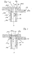
- FIG. 1 shows a part of a linear slide with an upper, fixedly arranged Slider plate 10 and an associated lower plate 12 (which moves in the direction of arrow L. can be) with attached sleeve 14.
- the plates 10, 12 and the sleeve 14 each have through openings 10d, 12d, 14d, each with a circular cross section, which is shown in FIG. 1 shown "flow position" for a Metal melt (in the direction of arrow M) a through channel 16 with a cylindrical wall surface 18 form.
- the slide plate 10 is with superimposed, fire-resistant, wear-resistant inserts 10e1, 10e2 formed, each having an annular shape, with the formation of the aforementioned Through opening 10d.
- the plate 12 is concentric with an insert 12e and opening 12d Through channel 16 formed.
- the sleeve 14 has a cylindrical wear insert 14e on.
- a compensating layer 20 is arranged, which has an annular shape, the Inner diameter corresponds to the diameter of the through opening 16 and the Outside diameter that of the insert 10e1, so that it is in the overlap area of the inserts 10e1 and 10e2 results in a 100% filling with the compensating layer 20, which consists of a second Ceramic fiber fleece is millimeter thick (FIG. 2).
- the insert 10e2 cannot expand downwards because its sliding surface 10g covers the entire surface rests on the sliding surface 12g of the plate 12.
- the compensation layer 20 makes it possible that the insert 10e2 grows "upwards", at least in the area adjacent to the Through opening 16. This results in a compression of the fiber layer and one de facto complete closure of the distance between the corresponding surfaces of the inserts 10e1, 10e2. In this way, thermal / mechanical stresses can be avoided.
- the area between the insert 12e and the sleeve 14 can also have a corresponding compensation layer are formed, as shown in FIG. 2 by a wavy line 22 shown.
- the compensation layer is only immediately adjacent to the To provide through opening 16 because there the greatest temperature load during casting occurs and thus the greatest thermal expansion takes place here.
- FIG. 3 shows a closure system with an upper plate 10, a lower plate 12 and one intermediate plate 11 disposed therebetween.
- a sleeve is connected to the lower plate 12 14 on.
- a sleeve 24 which connects to a pouring area 26 Metallurgical vessel not shown is connected.
- the sleeve 24 is assembled in a perforated brick arrangement 25.
- the sleeve 24 is formed in the connection area to the plate 10 with a peripheral step and correspondingly the plate 10.
- a fiber ring 20 which serves as a compensation layer and the based on FIG. 2 described function fulfilled.
- a corresponding arrangement can alternatively or cumulatively between plate 12 and sleeve 14 may be provided.
Landscapes
- Engineering & Computer Science (AREA)
- Mechanical Engineering (AREA)
- Casting Support Devices, Ladles, And Melt Control Thereby (AREA)
- Building Environments (AREA)
- Multiple-Way Valves (AREA)
- Sliding Valves (AREA)
- Coupling Device And Connection With Printed Circuit (AREA)
Abstract
Description
- Die Dichtigkeit des Systems, insbesondere im Bereich der zueinander bewegten Bauteile,
- Verhinderung einer Luftansaugung,
- Reduzierung des Verschleißes, insbesondere im Bereich des Durchgangskanals,
- Verhinderung von Anbackungen im Durchflußkanal.
- Die Baugruppe umfaßt mindestens zwei feuerfeste keramische Bauteile,
- jedes der beiden Bauteile weist eine Durchgangsöffnung auf,
- die beiden Bauteile der Baugruppe sind so gestaltet, dass ihre Durchgangsöffnungen einen gemeinsamen Durchgangskanal bilden,
- zumindest in einem, an den Durchgangskanal radial anschließenden Bereich ist zwischen den beiden Bauteilen eine komprimierbare Ausgleichsschicht angeordnet.
- FIG. 1: Einen Längsschnitt durch ein Linear-Schiebersystem gemäß Stand der Technik.
- FIG. 2: Eine Darstellung wie FIG. 1, jedoch unter Einsatz einer erfindungsgemäßen Baugruppe
- FIG. 3: Einen Längsschnitt durch ein Schiebersystem mit einer Baugruppe aus Schieberplatte und Hülse.
Claims (15)
- Baugruppe eines Schieberverschlusssystems, mit folgenden Merkmalen:1.1 die Baugruppe umfasst mindestens zwei feuerfeste keramische Bauteile (10, 10e1, 10e2, 12, 12e, 14, 14e)1.2 jedes der beiden Bauteile ( 10, 10e1, 10e2, 12, 12e, 14, 14e) weist eine Durchgangsöffnung (10d, 12d, 14d) auf,1.3 die beiden Bauteile (10, 10e1, 10e2, 12, 12e, 14, 14e) der Baugruppe sind so angeordnet, dass ihre Durchgangsöffnungen (10d, 12d, 14d) einen gemeinsamen Durchgangskanal (16) bilden,1.4 zumindest in einem, an den Durchgangskanal (16) radial anschließenden Bereich ist zwischen den beiden Bauteilen (10, 10e1, 10e2, 12, 12e, 14, 14e) eine komprimierbare Ausgleichsschicht (20, 22) angeordnet.
- Baugruppe nach Anspruch 1, bei der mindestens eines der Bauteile (10, 10e1, 10e2, 12, 12e, 14, 14e) eine Schieberplatte oder ein Teil (10e1, 10e2, 12e) einer Schieberplatte ist.
- Baugruppe nach Anspruch 1, bei der mindestens eines der Bauteile (14) eine Hülse (14) ist.
- Baugruppe nach Anspruch 1, bei der die Durchgangsöffnungen (10d, 12d, 14d) einen Kreisquerschnitt aufweisen.
- Baugruppe nach Anspruch 1, bei der die Ausgleichsschicht (20, 22) unmittelbar an den Durchgangskanal (16) anschließt.
- Baugruppe nach Anspruch 1, bei der die Ausgleichsschicht (20, 22) eine Ringform aufweist.
- Baugruppe nach Anspruch 1, bei der die Ausgleichsschicht (20, 22) senkrecht durch Mittenlängsachse (A) des Durchgangskanals (16) verläuft.
- Baugruppe nach Anspruch 1, bei der die Ausgleichsschicht (20, 22) aus einem hochtemperaturbeständigen Fasermaterial besteht.
- Baugruppe nach Anspruch 1, bei der die Ausgleichsschicht (20, 22) eine Dicke, parallel zur Mittenlängsachse (A) des Durchgangskanals (16), bis zu 25% der Dicke eines benachbarten Bauteils (10, 10e1, 10e2, 12, 12e, 14, 14e) aufweist.
- Baugruppe nach Anspruch 1, bei der die Ausgleichsschicht (20, 22) eine Dicke, parallel zur Mittenlängsachse (A) des Durchgangskanals (16), zwischen 0,2 und 10 % der Dicke eines benachbarten Bauteils (10, 10e1, 10e2, 12, 12e, 14, 14e) aufweist.
- Baugruppe nach Anspruch 1, bei der die Ausgleichsschicht (20, 22) eine Breite, radial zur Mittenlängsachse (A) des Durchgangskanals (16), von mindestens 2mm aufweist.
- Baugruppe nach Anspruch 1, bei der die Ausgleichsschicht (20, 22) sich über mindestens 20 % des Überdeckungsbereichs der beiden benachbarten Bauteile (10, 10e1, 10e2, 12, 12e, 14, 14e) erstreckt.
- Baugruppe nach Anspruch 1, bei der die Ausgleichsschicht (20, 22) sich über mindestens 50 % des Überdeckungsbereichs der beiden benachbarten Bauteile (10, 10e1, 10e2, 12, 12e, 14, 14e) erstreckt.
- Baugruppe nach Anspruch 1, bei der die Ausgleichsschicht mehrteilig ist.
- Baugruppe nach Anspruch 1, bei der die Durchgangsöffnungen (10d, 12d, 14d) benachbarter, eine Ausgleichsschicht (20) zwischen sich aufnehmender Bauteile (10e1, 10e2; 12e, 14e) fluchten.
Applications Claiming Priority (2)
| Application Number | Priority Date | Filing Date | Title |
|---|---|---|---|
| DE10222026A DE10222026C1 (de) | 2002-05-17 | 2002-05-17 | Baugruppe eines Schieberverschlußsystems |
| DE10222026 | 2002-05-17 |
Publications (3)
| Publication Number | Publication Date |
|---|---|
| EP1364730A2 true EP1364730A2 (de) | 2003-11-26 |
| EP1364730A3 EP1364730A3 (de) | 2004-09-08 |
| EP1364730B1 EP1364730B1 (de) | 2006-10-25 |
Family
ID=29285516
Family Applications (1)
| Application Number | Title | Priority Date | Filing Date |
|---|---|---|---|
| EP03001899A Expired - Lifetime EP1364730B1 (de) | 2002-05-17 | 2003-01-30 | Baugruppe eines Schieberverschlusssystems |
Country Status (4)
| Country | Link |
|---|---|
| EP (1) | EP1364730B1 (de) |
| AT (1) | ATE343445T1 (de) |
| DE (2) | DE10222026C1 (de) |
| ES (1) | ES2274133T3 (de) |
Family Cites Families (9)
| Publication number | Priority date | Publication date | Assignee | Title |
|---|---|---|---|---|
| DE2719105B2 (de) * | 1977-04-29 | 1979-10-31 | Didier-Werke Ag, 6200 Wiesbaden | Feuerfeste Platte für Schieberverschlüsse an metallurgischen Gefäßen |
| GB1589659A (en) * | 1977-05-13 | 1981-05-20 | Vysoka Skola Chem Tech | Refractory plates |
| DE3226047C2 (de) * | 1982-07-12 | 1985-11-28 | Didier-Werke Ag, 6200 Wiesbaden | Verbindung zwischen dem Auslaufkonus des Verschlusses eines Gießgefäßes für Metallschmelze und dem daran anschließenden Schutzrohr |
| JPS6340653A (ja) * | 1986-08-06 | 1988-02-22 | Nippon Kokan Kk <Nkk> | 溶湯注入装置 |
| GB8705224D0 (en) * | 1987-03-06 | 1987-04-08 | Thor Ceramics Ltd | Refractory assemblies |
| DE3926371A1 (de) * | 1988-08-11 | 1990-02-15 | Flo Con Syst | Dichtung |
| DE4129194C2 (de) * | 1991-09-03 | 1996-08-22 | Didier Werke Ag | Verfahren zur Herstellung eines flexiblen, kompressiblen feuerfesten Fugenwerkstoffs |
| WO1995010492A1 (fr) * | 1993-10-15 | 1995-04-20 | Shinagawa Refractories Co., Ltd. | Enveloppe de materiau refractaire |
| DE4401008C2 (de) * | 1994-01-15 | 1999-09-16 | Didier Werke Ag | Schieberplatte |
-
2002
- 2002-05-17 DE DE10222026A patent/DE10222026C1/de not_active Expired - Fee Related
-
2003
- 2003-01-30 ES ES03001899T patent/ES2274133T3/es not_active Expired - Lifetime
- 2003-01-30 AT AT03001899T patent/ATE343445T1/de active
- 2003-01-30 EP EP03001899A patent/EP1364730B1/de not_active Expired - Lifetime
- 2003-01-30 DE DE50305461T patent/DE50305461D1/de not_active Expired - Lifetime
Also Published As
| Publication number | Publication date |
|---|---|
| ATE343445T1 (de) | 2006-11-15 |
| EP1364730A3 (de) | 2004-09-08 |
| DE10222026C1 (de) | 2003-11-27 |
| ES2274133T3 (es) | 2007-05-16 |
| DE50305461D1 (de) | 2006-12-07 |
| EP1364730B1 (de) | 2006-10-25 |
Similar Documents
| Publication | Publication Date | Title |
|---|---|---|
| EP0021029B1 (de) | Ventil mit geräuschdämmenden Einbauten | |
| DE29623867U1 (de) | Filterelement für einen Flüssigkeitsfilter mit Filterumgehungsventil und filterelementseitiger Dichtfläche | |
| DE4343658A1 (de) | Gleitverbindungsvorrichtung zwischen zwei Teilen, die starken mechanischen und thermischen Belastungen unterliegen | |
| DE4403517A1 (de) | Absperrschieber | |
| EP0243587B1 (de) | Feuerfester Formkörper, insbesondere Platte für Schieberverschlüsse | |
| WO1985005584A1 (fr) | Coulee ceramique | |
| DE2243517C3 (de) | Feuerfeste Wandkonstruktion | |
| EP1403572A2 (de) | Mehrlagige Zylinderkopfdichtung | |
| WO2015169466A1 (de) | Feuerfestes keramisches gasspülelement | |
| DE10222026C1 (de) | Baugruppe eines Schieberverschlußsystems | |
| EP1817528B1 (de) | Verfahren zur herstellung eines hitzeschildelementes | |
| DE4231686A1 (de) | Verschlussplatte fuer einen schiebeverschluss an einem metallschmelze enthaltenden behaelter | |
| DE69112133T2 (de) | Umschaltventil. | |
| EP2516086A1 (de) | Schiebeverschluss für einen metallurgischen behälter | |
| DE3809071A1 (de) | Dreh- und/oder schieberverschluss fuer einen ausguss eines metallschmelze enthaltenden gefaesses, sowie verschlussteile fuer einen solchen verschluss | |
| WO2014154364A1 (de) | Wölbstein zylinderförmige innere auskleidung eines drehrohrofens und drehrohrofen | |
| EP1711292B1 (de) | Schieberplatte für einen Schieberverschluss an metallurgischen Schmelzgefässen sowie Verfahren zur deren Herstellung | |
| WO2009033633A1 (de) | Feuerfester keramischer adapter | |
| DE3227469C2 (de) | Verschlußeinrichtung | |
| DE4042203C2 (de) | Schieberplatte für Schieberverschlüsse von metallurgischen Gefäßen | |
| DE2242087C2 (de) | Absperrschieber | |
| DE19860552A1 (de) | Kühlbarer Verbrennungsrost | |
| EP0204896B1 (de) | Reparaturset für Schieberplatten | |
| DE19917851C2 (de) | Drehschieberplatte | |
| EP1797976A2 (de) | Spülkegel |
Legal Events
| Date | Code | Title | Description |
|---|---|---|---|
| PUAI | Public reference made under article 153(3) epc to a published international application that has entered the european phase |
Free format text: ORIGINAL CODE: 0009012 |
|
| AK | Designated contracting states |
Kind code of ref document: A2 Designated state(s): AT BE BG CH CY CZ DE DK EE ES FI FR GB GR HU IE IT LI LU MC NL PT SE SI SK TR |
|
| AX | Request for extension of the european patent |
Extension state: AL LT LV MK RO SI |
|
| RIN1 | Information on inventor provided before grant (corrected) |
Inventor name: MEIER, PETER Inventor name: PISCHEK, STEFAN Inventor name: WINKELMANN, MANFRED |
|
| PUAL | Search report despatched |
Free format text: ORIGINAL CODE: 0009013 |
|
| RIC1 | Information provided on ipc code assigned before grant |
Ipc: 7B 22D 41/28 B Ipc: 7B 22D 41/24 A Ipc: 7B 22D 41/50 B |
|
| AK | Designated contracting states |
Kind code of ref document: A3 Designated state(s): AT BE BG CH CY CZ DE DK EE ES FI FR GB GR HU IE IT LI LU MC NL PT SE SI SK TR |
|
| AX | Request for extension of the european patent |
Extension state: AL LT LV MK RO |
|
| 17P | Request for examination filed |
Effective date: 20040824 |
|
| 17Q | First examination report despatched |
Effective date: 20050311 |
|
| AKX | Designation fees paid |
Designated state(s): AT BE BG CH CY CZ DE DK EE ES FI FR GB GR HU IE IT LI LU MC NL PT SE SI SK TR |
|
| GRAP | Despatch of communication of intention to grant a patent |
Free format text: ORIGINAL CODE: EPIDOSNIGR1 |
|
| GRAS | Grant fee paid |
Free format text: ORIGINAL CODE: EPIDOSNIGR3 |
|
| GRAA | (expected) grant |
Free format text: ORIGINAL CODE: 0009210 |
|
| AK | Designated contracting states |
Kind code of ref document: B1 Designated state(s): AT BE BG CH CY CZ DE DK EE ES FI FR GB GR HU IE IT LI LU MC NL PT SE SI SK TR |
|
| PG25 | Lapsed in a contracting state [announced via postgrant information from national office to epo] |
Ref country code: SI Free format text: LAPSE BECAUSE OF FAILURE TO SUBMIT A TRANSLATION OF THE DESCRIPTION OR TO PAY THE FEE WITHIN THE PRESCRIBED TIME-LIMIT Effective date: 20061025 Ref country code: FI Free format text: LAPSE BECAUSE OF FAILURE TO SUBMIT A TRANSLATION OF THE DESCRIPTION OR TO PAY THE FEE WITHIN THE PRESCRIBED TIME-LIMIT Effective date: 20061025 Ref country code: IE Free format text: LAPSE BECAUSE OF FAILURE TO SUBMIT A TRANSLATION OF THE DESCRIPTION OR TO PAY THE FEE WITHIN THE PRESCRIBED TIME-LIMIT Effective date: 20061025 Ref country code: SK Free format text: LAPSE BECAUSE OF FAILURE TO SUBMIT A TRANSLATION OF THE DESCRIPTION OR TO PAY THE FEE WITHIN THE PRESCRIBED TIME-LIMIT Effective date: 20061025 Ref country code: CZ Free format text: LAPSE BECAUSE OF FAILURE TO SUBMIT A TRANSLATION OF THE DESCRIPTION OR TO PAY THE FEE WITHIN THE PRESCRIBED TIME-LIMIT Effective date: 20061025 |
|
| REG | Reference to a national code |
Ref country code: GB Ref legal event code: FG4D Free format text: NOT ENGLISH |
|
| REG | Reference to a national code |
Ref country code: CH Ref legal event code: EP |
|
| REG | Reference to a national code |
Ref country code: SE Ref legal event code: TRGR |
|
| REG | Reference to a national code |
Ref country code: IE Ref legal event code: FG4D Free format text: LANGUAGE OF EP DOCUMENT: GERMAN |
|
| REF | Corresponds to: |
Ref document number: 50305461 Country of ref document: DE Date of ref document: 20061207 Kind code of ref document: P |
|
| GBT | Gb: translation of ep patent filed (gb section 77(6)(a)/1977) |
Effective date: 20061213 |
|
| PG25 | Lapsed in a contracting state [announced via postgrant information from national office to epo] |
Ref country code: BG Free format text: LAPSE BECAUSE OF FAILURE TO SUBMIT A TRANSLATION OF THE DESCRIPTION OR TO PAY THE FEE WITHIN THE PRESCRIBED TIME-LIMIT Effective date: 20070125 Ref country code: DK Free format text: LAPSE BECAUSE OF FAILURE TO SUBMIT A TRANSLATION OF THE DESCRIPTION OR TO PAY THE FEE WITHIN THE PRESCRIBED TIME-LIMIT Effective date: 20070125 |
|
| PG25 | Lapsed in a contracting state [announced via postgrant information from national office to epo] |
Ref country code: CH Free format text: LAPSE BECAUSE OF NON-PAYMENT OF DUE FEES Effective date: 20070131 Ref country code: LI Free format text: LAPSE BECAUSE OF NON-PAYMENT OF DUE FEES Effective date: 20070131 Ref country code: MC Free format text: LAPSE BECAUSE OF NON-PAYMENT OF DUE FEES Effective date: 20070131 |
|
| ET | Fr: translation filed | ||
| PG25 | Lapsed in a contracting state [announced via postgrant information from national office to epo] |
Ref country code: PT Free format text: LAPSE BECAUSE OF FAILURE TO SUBMIT A TRANSLATION OF THE DESCRIPTION OR TO PAY THE FEE WITHIN THE PRESCRIBED TIME-LIMIT Effective date: 20070326 |
|
| REG | Reference to a national code |
Ref country code: ES Ref legal event code: FG2A Ref document number: 2274133 Country of ref document: ES Kind code of ref document: T3 |
|
| REG | Reference to a national code |
Ref country code: IE Ref legal event code: FD4D |
|
| PLBE | No opposition filed within time limit |
Free format text: ORIGINAL CODE: 0009261 |
|
| STAA | Information on the status of an ep patent application or granted ep patent |
Free format text: STATUS: NO OPPOSITION FILED WITHIN TIME LIMIT |
|
| REG | Reference to a national code |
Ref country code: CH Ref legal event code: PL |
|
| 26N | No opposition filed |
Effective date: 20070726 |
|
| PG25 | Lapsed in a contracting state [announced via postgrant information from national office to epo] |
Ref country code: GR Free format text: LAPSE BECAUSE OF FAILURE TO SUBMIT A TRANSLATION OF THE DESCRIPTION OR TO PAY THE FEE WITHIN THE PRESCRIBED TIME-LIMIT Effective date: 20070126 |
|
| PG25 | Lapsed in a contracting state [announced via postgrant information from national office to epo] |
Ref country code: EE Free format text: LAPSE BECAUSE OF FAILURE TO SUBMIT A TRANSLATION OF THE DESCRIPTION OR TO PAY THE FEE WITHIN THE PRESCRIBED TIME-LIMIT Effective date: 20061025 |
|
| PG25 | Lapsed in a contracting state [announced via postgrant information from national office to epo] |
Ref country code: CY Free format text: LAPSE BECAUSE OF FAILURE TO SUBMIT A TRANSLATION OF THE DESCRIPTION OR TO PAY THE FEE WITHIN THE PRESCRIBED TIME-LIMIT Effective date: 20061025 |
|
| PG25 | Lapsed in a contracting state [announced via postgrant information from national office to epo] |
Ref country code: TR Free format text: LAPSE BECAUSE OF FAILURE TO SUBMIT A TRANSLATION OF THE DESCRIPTION OR TO PAY THE FEE WITHIN THE PRESCRIBED TIME-LIMIT Effective date: 20061025 Ref country code: HU Free format text: LAPSE BECAUSE OF FAILURE TO SUBMIT A TRANSLATION OF THE DESCRIPTION OR TO PAY THE FEE WITHIN THE PRESCRIBED TIME-LIMIT Effective date: 20070426 |
|
| PGFP | Annual fee paid to national office [announced via postgrant information from national office to epo] |
Ref country code: IT Payment date: 20120126 Year of fee payment: 10 |
|
| PGFP | Annual fee paid to national office [announced via postgrant information from national office to epo] |
Ref country code: LU Payment date: 20130123 Year of fee payment: 11 |
|
| PGFP | Annual fee paid to national office [announced via postgrant information from national office to epo] |
Ref country code: SE Payment date: 20130122 Year of fee payment: 11 Ref country code: GB Payment date: 20130122 Year of fee payment: 11 Ref country code: FR Payment date: 20130207 Year of fee payment: 11 Ref country code: DE Payment date: 20130128 Year of fee payment: 11 Ref country code: ES Payment date: 20130122 Year of fee payment: 11 |
|
| PGFP | Annual fee paid to national office [announced via postgrant information from national office to epo] |
Ref country code: BE Payment date: 20130121 Year of fee payment: 11 Ref country code: NL Payment date: 20130121 Year of fee payment: 11 |
|
| PGFP | Annual fee paid to national office [announced via postgrant information from national office to epo] |
Ref country code: AT Payment date: 20130121 Year of fee payment: 11 |
|
| BERE | Be: lapsed |
Owner name: *REFRACTORY INTELLECTUAL PTY GMBH & CO. K.G. Effective date: 20140131 |
|
| REG | Reference to a national code |
Ref country code: DE Ref legal event code: R119 Ref document number: 50305461 Country of ref document: DE |
|
| REG | Reference to a national code |
Ref country code: NL Ref legal event code: V1 Effective date: 20140801 |
|
| PG25 | Lapsed in a contracting state [announced via postgrant information from national office to epo] |
Ref country code: LU Free format text: LAPSE BECAUSE OF NON-PAYMENT OF DUE FEES Effective date: 20140130 |
|
| REG | Reference to a national code |
Ref country code: AT Ref legal event code: MM01 Ref document number: 343445 Country of ref document: AT Kind code of ref document: T Effective date: 20140130 |
|
| REG | Reference to a national code |
Ref country code: SE Ref legal event code: EUG |
|
| GBPC | Gb: european patent ceased through non-payment of renewal fee |
Effective date: 20140130 |
|
| REG | Reference to a national code |
Ref country code: DE Ref legal event code: R119 Ref document number: 50305461 Country of ref document: DE Effective date: 20140801 |
|
| PG25 | Lapsed in a contracting state [announced via postgrant information from national office to epo] |
Ref country code: NL Free format text: LAPSE BECAUSE OF NON-PAYMENT OF DUE FEES Effective date: 20140801 Ref country code: DE Free format text: LAPSE BECAUSE OF NON-PAYMENT OF DUE FEES Effective date: 20140801 |
|
| REG | Reference to a national code |
Ref country code: FR Ref legal event code: ST Effective date: 20140930 |
|
| PG25 | Lapsed in a contracting state [announced via postgrant information from national office to epo] |
Ref country code: GB Free format text: LAPSE BECAUSE OF NON-PAYMENT OF DUE FEES Effective date: 20140130 Ref country code: SE Free format text: LAPSE BECAUSE OF NON-PAYMENT OF DUE FEES Effective date: 20140131 Ref country code: FR Free format text: LAPSE BECAUSE OF NON-PAYMENT OF DUE FEES Effective date: 20140131 Ref country code: AT Free format text: LAPSE BECAUSE OF NON-PAYMENT OF DUE FEES Effective date: 20140130 |
|
| PG25 | Lapsed in a contracting state [announced via postgrant information from national office to epo] |
Ref country code: BE Free format text: LAPSE BECAUSE OF NON-PAYMENT OF DUE FEES Effective date: 20140131 |
|
| REG | Reference to a national code |
Ref country code: ES Ref legal event code: FD2A Effective date: 20150730 |
|
| PG25 | Lapsed in a contracting state [announced via postgrant information from national office to epo] |
Ref country code: ES Free format text: LAPSE BECAUSE OF NON-PAYMENT OF DUE FEES Effective date: 20140131 |
|
| PG25 | Lapsed in a contracting state [announced via postgrant information from national office to epo] |
Ref country code: IT Free format text: LAPSE BECAUSE OF NON-PAYMENT OF DUE FEES Effective date: 20140130 |